EP0830228B1 - Procede d'usinage par enlevement de copeaux de contours cylindriques, dispositif de mise en uvre du procede et plaquette de coupe associee - Google Patents
Procede d'usinage par enlevement de copeaux de contours cylindriques, dispositif de mise en uvre du procede et plaquette de coupe associee Download PDFInfo
- Publication number
- EP0830228B1 EP0830228B1 EP96919612A EP96919612A EP0830228B1 EP 0830228 B1 EP0830228 B1 EP 0830228B1 EP 96919612 A EP96919612 A EP 96919612A EP 96919612 A EP96919612 A EP 96919612A EP 0830228 B1 EP0830228 B1 EP 0830228B1
- Authority
- EP
- European Patent Office
- Prior art keywords
- cutting
- tool
- inserts
- angle
- machining
- Prior art date
- Legal status (The legal status is an assumption and is not a legal conclusion. Google has not performed a legal analysis and makes no representation as to the accuracy of the status listed.)
- Revoked
Links
Images

Classifications
-
- B—PERFORMING OPERATIONS; TRANSPORTING
- B23—MACHINE TOOLS; METAL-WORKING NOT OTHERWISE PROVIDED FOR
- B23C—MILLING
- B23C3/00—Milling particular work; Special milling operations; Machines therefor
- B23C3/06—Milling crankshafts
-
- B—PERFORMING OPERATIONS; TRANSPORTING
- B23—MACHINE TOOLS; METAL-WORKING NOT OTHERWISE PROVIDED FOR
- B23C—MILLING
- B23C5/00—Milling-cutters
- B23C5/16—Milling-cutters characterised by physical features other than shape
- B23C5/20—Milling-cutters characterised by physical features other than shape with removable cutter bits or teeth or cutting inserts
- B23C5/202—Plate-like cutting inserts with special form
-
- B—PERFORMING OPERATIONS; TRANSPORTING
- B23—MACHINE TOOLS; METAL-WORKING NOT OTHERWISE PROVIDED FOR
- B23C—MILLING
- B23C2200/00—Details of milling cutting inserts
- B23C2200/20—Top or side views of the cutting edge
- B23C2200/201—Details of the nose radius and immediately surrounding areas
-
- B—PERFORMING OPERATIONS; TRANSPORTING
- B23—MACHINE TOOLS; METAL-WORKING NOT OTHERWISE PROVIDED FOR
- B23C—MILLING
- B23C2200/00—Details of milling cutting inserts
- B23C2200/20—Top or side views of the cutting edge
- B23C2200/205—Discontinuous cutting edges
-
- B—PERFORMING OPERATIONS; TRANSPORTING
- B23—MACHINE TOOLS; METAL-WORKING NOT OTHERWISE PROVIDED FOR
- B23C—MILLING
- B23C2215/00—Details of workpieces
- B23C2215/20—Crankshafts
-
- Y—GENERAL TAGGING OF NEW TECHNOLOGICAL DEVELOPMENTS; GENERAL TAGGING OF CROSS-SECTIONAL TECHNOLOGIES SPANNING OVER SEVERAL SECTIONS OF THE IPC; TECHNICAL SUBJECTS COVERED BY FORMER USPC CROSS-REFERENCE ART COLLECTIONS [XRACs] AND DIGESTS
- Y10—TECHNICAL SUBJECTS COVERED BY FORMER USPC
- Y10T—TECHNICAL SUBJECTS COVERED BY FORMER US CLASSIFICATION
- Y10T29/00—Metal working
- Y10T29/17—Crankshaft making apparatus
-
- Y—GENERAL TAGGING OF NEW TECHNOLOGICAL DEVELOPMENTS; GENERAL TAGGING OF CROSS-SECTIONAL TECHNOLOGIES SPANNING OVER SEVERAL SECTIONS OF THE IPC; TECHNICAL SUBJECTS COVERED BY FORMER USPC CROSS-REFERENCE ART COLLECTIONS [XRACs] AND DIGESTS
- Y10—TECHNICAL SUBJECTS COVERED BY FORMER USPC
- Y10T—TECHNICAL SUBJECTS COVERED BY FORMER US CLASSIFICATION
- Y10T29/00—Metal working
- Y10T29/49—Method of mechanical manufacture
- Y10T29/49229—Prime mover or fluid pump making
- Y10T29/49286—Crankshaft making
-
- Y—GENERAL TAGGING OF NEW TECHNOLOGICAL DEVELOPMENTS; GENERAL TAGGING OF CROSS-SECTIONAL TECHNOLOGIES SPANNING OVER SEVERAL SECTIONS OF THE IPC; TECHNICAL SUBJECTS COVERED BY FORMER USPC CROSS-REFERENCE ART COLLECTIONS [XRACs] AND DIGESTS
- Y10—TECHNICAL SUBJECTS COVERED BY FORMER USPC
- Y10T—TECHNICAL SUBJECTS COVERED BY FORMER US CLASSIFICATION
- Y10T29/00—Metal working
- Y10T29/51—Plural diverse manufacturing apparatus including means for metal shaping or assembling
- Y10T29/5104—Type of machine
- Y10T29/5109—Lathe
-
- Y—GENERAL TAGGING OF NEW TECHNOLOGICAL DEVELOPMENTS; GENERAL TAGGING OF CROSS-SECTIONAL TECHNOLOGIES SPANNING OVER SEVERAL SECTIONS OF THE IPC; TECHNICAL SUBJECTS COVERED BY FORMER USPC CROSS-REFERENCE ART COLLECTIONS [XRACs] AND DIGESTS
- Y10—TECHNICAL SUBJECTS COVERED BY FORMER USPC
- Y10T—TECHNICAL SUBJECTS COVERED BY FORMER US CLASSIFICATION
- Y10T407/00—Cutters, for shaping
- Y10T407/23—Cutters, for shaping including tool having plural alternatively usable cutting edges
-
- Y—GENERAL TAGGING OF NEW TECHNOLOGICAL DEVELOPMENTS; GENERAL TAGGING OF CROSS-SECTIONAL TECHNOLOGIES SPANNING OVER SEVERAL SECTIONS OF THE IPC; TECHNICAL SUBJECTS COVERED BY FORMER USPC CROSS-REFERENCE ART COLLECTIONS [XRACs] AND DIGESTS
- Y10—TECHNICAL SUBJECTS COVERED BY FORMER USPC
- Y10T—TECHNICAL SUBJECTS COVERED BY FORMER US CLASSIFICATION
- Y10T407/00—Cutters, for shaping
- Y10T407/27—Cutters, for shaping comprising tool of specific chemical composition
-
- Y—GENERAL TAGGING OF NEW TECHNOLOGICAL DEVELOPMENTS; GENERAL TAGGING OF CROSS-SECTIONAL TECHNOLOGIES SPANNING OVER SEVERAL SECTIONS OF THE IPC; TECHNICAL SUBJECTS COVERED BY FORMER USPC CROSS-REFERENCE ART COLLECTIONS [XRACs] AND DIGESTS
- Y10—TECHNICAL SUBJECTS COVERED BY FORMER USPC
- Y10T—TECHNICAL SUBJECTS COVERED BY FORMER US CLASSIFICATION
- Y10T409/00—Gear cutting, milling, or planing
- Y10T409/30—Milling
- Y10T409/303752—Process
- Y10T409/303808—Process including infeeding
-
- Y—GENERAL TAGGING OF NEW TECHNOLOGICAL DEVELOPMENTS; GENERAL TAGGING OF CROSS-SECTIONAL TECHNOLOGIES SPANNING OVER SEVERAL SECTIONS OF THE IPC; TECHNICAL SUBJECTS COVERED BY FORMER USPC CROSS-REFERENCE ART COLLECTIONS [XRACs] AND DIGESTS
- Y10—TECHNICAL SUBJECTS COVERED BY FORMER USPC
- Y10T—TECHNICAL SUBJECTS COVERED BY FORMER US CLASSIFICATION
- Y10T409/00—Gear cutting, milling, or planing
- Y10T409/30—Milling
- Y10T409/304536—Milling including means to infeed work to cutter
- Y10T409/305544—Milling including means to infeed work to cutter with work holder
- Y10T409/305656—Milling including means to infeed work to cutter with work holder including means to support work for rotation during operation
-
- Y—GENERAL TAGGING OF NEW TECHNOLOGICAL DEVELOPMENTS; GENERAL TAGGING OF CROSS-SECTIONAL TECHNOLOGIES SPANNING OVER SEVERAL SECTIONS OF THE IPC; TECHNICAL SUBJECTS COVERED BY FORMER USPC CROSS-REFERENCE ART COLLECTIONS [XRACs] AND DIGESTS
- Y10—TECHNICAL SUBJECTS COVERED BY FORMER USPC
- Y10T—TECHNICAL SUBJECTS COVERED BY FORMER US CLASSIFICATION
- Y10T409/00—Gear cutting, milling, or planing
- Y10T409/30—Milling
- Y10T409/306664—Milling including means to infeed rotary cutter toward work
- Y10T409/306776—Axially
- Y10T409/307056—Axially and laterally
-
- Y—GENERAL TAGGING OF NEW TECHNOLOGICAL DEVELOPMENTS; GENERAL TAGGING OF CROSS-SECTIONAL TECHNOLOGIES SPANNING OVER SEVERAL SECTIONS OF THE IPC; TECHNICAL SUBJECTS COVERED BY FORMER USPC CROSS-REFERENCE ART COLLECTIONS [XRACs] AND DIGESTS
- Y10—TECHNICAL SUBJECTS COVERED BY FORMER USPC
- Y10T—TECHNICAL SUBJECTS COVERED BY FORMER US CLASSIFICATION
- Y10T409/00—Gear cutting, milling, or planing
- Y10T409/30—Milling
- Y10T409/306664—Milling including means to infeed rotary cutter toward work
- Y10T409/30756—Machining arcuate surface
-
- Y—GENERAL TAGGING OF NEW TECHNOLOGICAL DEVELOPMENTS; GENERAL TAGGING OF CROSS-SECTIONAL TECHNOLOGIES SPANNING OVER SEVERAL SECTIONS OF THE IPC; TECHNICAL SUBJECTS COVERED BY FORMER USPC CROSS-REFERENCE ART COLLECTIONS [XRACs] AND DIGESTS
- Y10—TECHNICAL SUBJECTS COVERED BY FORMER USPC
- Y10T—TECHNICAL SUBJECTS COVERED BY FORMER US CLASSIFICATION
- Y10T82/00—Turning
- Y10T82/19—Lathe for crank or crank pin
Definitions
- the invention relates to a cutting insert and a milling method for machining of cylindrical contours, of eccentric arranged cylindrical contours on one around its longitudinal axis rotating workpiece, of centrally clamped Crankshaft bearings by means of rotatable, drivable Tools in which a finished contour is generated in such a way that these either with sufficient surface quality has or an oversize to carry out a finishing, such as grinding or finishing, wherein for Production of the finished contour using cutting inserts according to the invention, in particular Inserts equipped tools one after the other or brought into engagement with the workpiece at the same time be, as well as a device for performing the method with at least one tool with cutting inserts.
- Crankshaft pin bearings are machined according to a known method through revolving spaces or revolving revolving spaces like that, that the crankshaft is mounted eccentrically to a pure Rotation around the central axis of the crank pin.
- this Storage is also possible for honeycomb processing, however this type of processing proved to be prone to failure, in addition, the chucks are for eccentric storage of the Crankshaft expensive. Added to this is the fact that machining is done by turning done with a tool so that in one operation a finished profile is generated that only in the area of Tenon still needs finishing by grinding. During this processing, different crankshaft thrust bearings must be used for each a different tool can be used.
- tool carriers are used according to the prior art used, with several on the tool carrier Find insert types.
- US-A-2 290 324 describes a machining process of crankshafts that are clamped on both sides and rotating be moved relative to the milling tools.
- An internal milling cutter is known from EP 0372717 A2, which also allows this milling pin bearing rotates.
- US-A-3 279 034 describes a milling cutter with cutting inserts, whose rake face is convex.
- the cheeks and undercuts are created using these tool carriers on both sides of the contour and the spigot over the entire Width made in one cut. Per finished contour a tool carrier is therefore required.
- a milling head for creating a bearing profile on a crankshaft in one operation is known from DE 38 24 348 A1.
- the proposed milling head in disc or swivel design for machining crankshafts that are to be machined Surfaces a parallel to the milling head axis Cylinder surface included, preferably on both sides a rotationally symmetrical shaped throat area in an approximate Surface perpendicular to the axis merges with the outer or inner
- the cutting circumference of the milling head in the holder Sets of indexable inserts is designed so that several Sets of indexable inserts evenly on the circumference of the cutting edge the milling head are arranged so that each set of indexable inserts completely the meridian contour of the to be machined Covered surface of the workpiece and that inside a set of indexable inserts for each specific one Machining surface section of the workpiece at least one Indexable insert is provided with special indexable inserts equipped so that all edge surfaces to be created can be edited simultaneously.
- a cutting insert to be called an indexable insert the a polygonal flat body with at least one main cutting edge, has a chip and a free surface known from DE 44 00 570.
- EP 0505574 A1 describes one in its basic form square cutting insert that is close to the cutting corner bevelled and recessed flat open space sections has a negative chamfer at one cutting end is formed.
- High-speed milling can produce good surface qualities generated that the pre-grinding or additional Pretreatments before the heat treatment as an additional Work process can be completely eliminated.
- At least some of the cutting inserts preferably all cutting inserts, have a positive rake angle.
- the cutting insert setting for the workpiece is carried out in such a way that the effective rake angle between -5 ° and + 15 °, preferably -5 ° to + 5 °, and / or a positive axial rake angle (rake angle ⁇ p ) up to 10 ° is selected.
- the method according to the invention is a processing mode that are particularly suitable for machining eccentrically arranged cylindrical contours, especially of crankshaft thrust bearings, suitable for a centrally clamped workpiece. Therefore, both the problematic pin bearings can be manufactured as well as the main bearings on the same device or with series or parallel connection of several devices be manufactured on similar devices.
- the production of the finished contour which as such already has final dimensions has or an oversize that by grinding or Finishing can be done away with with tools
- Cutting inserts loaded one after the other or simultaneously engaged with the workpiece is also called called so-called cut division.
- a division or processing with split tool it is possible to change the bearing width vary within certain limits, i.e. also different wide bearings with a right and a left tool generate and / or changes in bearing width as a result of Tool wear through adjustment using a Correct NC control.
- the machining is done so that the tool with constant or variable high speed is driven so that high-speed machining is achieved.
- the speed is variable, this is gradually changed linearly.
- This can take advantage of high speed milling cutters can now also be achieved in crankshaft machining, namely increasing the surface quality, increasing the Dimensional accuracy and reduction of processing times.
- high speed milling it was necessary to overcome various prejudices and problems. It was like that Use of the already known cutting inserts in existing Tool on known devices not possible, because too high forces and excessive heating for the tools resulted. With unstable crankshafts, there may be a great tendency to vibrate on. This can be counteracted by the fact that a It is divided into at least two milling processes. The division realizes various advantages.
- the tools are with corresponding ones High speed milling cutters.
- the cutting inserts designed and arranged so that in one puncture each about half of the finished contour of the pin can be generated.
- a side milling cutter is preferably used for this used.
- the rake faces preferably have used cutting inserts in the area of a cutting corner main cutting edge forming a flattening or indentation, which are in the area of both adjacent main cutting edges extends.
- the machining temperature is lowered to forces acting on the tool and thus the vibration excitation further decreased.
- Another advantage of the method according to the invention is in that in the case of the division of the cutting inserts, in particular of indexable inserts for the production of right and left half of the contour, the wear on the cutting inserts by moving the tool axially or radially Direction can be compensated.
- a further embodiment of the device provides that at least a tool carrier is an orthogonal milling cutter.
- the device for carrying out the machining process according to the invention one support per crankshaft thrust bearing have the for milling operations with at least one trackable Axis and for orthogonal rotary milling with two trackable Axes is equipped so that the tool is dependent are tracked by the angle of rotation of the workpiece can that after machining the eccentric arranged crankshaft thrust bearing a cylindrical correction results and the correction processes described above to compensate of indexable insert wear.
- the special procedure is that the tool on an axis depending on the angle of rotation of the workpiece is tracked so that after machining results in a cylindrical contour. Because of the high cutting speed and the low chip thicknesses result low forces on the workpiece, which means machining on the favor unstable workpiece. Simultaneously arise from the lower feed rates and the high cutting speeds better surface qualities than these so far comparable procedures could be achieved.
- a device is therefore designed such that the cutting process to produce the finished contour in at least two cutting processes are divided (cutting division), the tool carriers equipped with indexable inserts be engaged one after the other and the tool carrier are only equipped with indexable inserts that one have positive rake angle, the device at least has two tools provided with cutting inserts, each tool one with appropriate cutting inserts provided high speed milling cutter according to claim 5.
- a side milling cutter is preferably used as the tool, which is provided with appropriate indexable inserts, which enable high-speed milling. With a orthogonal milling cutter is an optimal tenoning feasible.
- the cutting insert has a polygonal flat body which is known per se and is preferably designed such that a positive cutting angle results when it is used on the workpiece.
- the cutting temperature is reduced by the positive cutting angle, and the forces acting on the tool and thus the vibration excitation are minimized.
- the design is such that the sum of the clearance angle and the wedge angle is between 85 ° and 95 °, which results in an effective rake angle ⁇ f between -5 ° and + 5 °. Possibly. the rake angle can also be up to 15 °.
- the rake angle ⁇ p is chosen positive and should not exceed 10 °.
- the free surface defined in each case in claim 10 becomes the effective rake surface, while conversely the rake surface is used as the effective free surface. This results in a corresponding manner that the effective open area has the flattening or indentation described above. Depending on the function, two or four flattenings or indentations are possible per cutting insert.
- the width of the cutting body or the width of the main cutting edge to be used advantageously about greater than or equal to half the width of the machining pin width is selected so that by the successive use of two cutting elements one optimal cone surface is created.
- a special cutting insert is proposed in which is that support is provided for at least one tool which is a movability of the tool in two directions perpendicular to each other.
- This special Training is optimally adapted to the application.
- the rake face in the area of Cutting edge has a flattening or indentation, i.e. that in the manufacture of such a cutting insert in Area of the cutter corner is attached to a surface causes the cutting corner opposite the main cutting edge back. This leads to a smoother transition in the overlap area the areas of application of two such insert bodies, so that in the investigation, for example the Pin surface of a crankshaft crank pin both measurable and an optimal surface is also achieved optically.
- the service life of such a cutting insert in particular in the area of the cutting body corners or the cutting body corners is particularly high, is to increase further provided that in the area of the cutting corners flattening or Indentations can be attached as support surfaces.
- stabilization is particularly suitable for cutting inserts that are in a so-called split tool for cutting division come.
- the diameter-producing insert of the first This tool cuts through positive rake angles highly vulnerable cutting corner 90 ° into the full material of the workpiece.
- By attaching support surfaces to the open spaces the cutting corners can have an additional area there Stabilization is done without relying on the positive chip shape geometry and / or to dispense with the four cutting edges of the cutting insert.
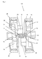
- Fig. 1 is a device 100 for machining purely schematic with regard to those related to the present invention shown the main components that all in a machine frame not shown in the drawing are arranged.
- the workpiece 10, namely a crankshaft, is with its ends 11 and 12 in drivable, rotatable Chuck chucks 13, 14 clamped so that they about their central longitudinal axis is rotatable.
- the disc-shaped high-speed tools are used for machining 15, 16, the corresponding drives 17, 18th are drivable, each drive 17, 18 on a support 19, 20 is mounted, whereby the tool on one axis the workpiece is tracked.
- orthogonal rotary milling cutters in the device 100 21, 22 arranged, which also have corresponding Drives 23, 24 are driven in rotation.
- Any orthogonal milling cutter 21, 22 is on a support with two slides 25, 26; 27, 28 mounted so that a tracking of each orthogonal Rotary milling cutter 21, 22 also possible with the crankshaft rotating is.
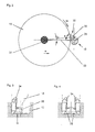
- a high speed tool works like it can be used in the device 100 is purely schematic shown in Fig. 2. It's about machining one outside the center of rotation 29 of the workpiece 10 to perform eccentrically arranged crankshaft thrust bearing 30, the disk-shaped tool 15 about its central axis 31 driven at constant or variable high speed, so that the not shown in the drawing, on the Inserted outer periphery, namely the indexable inserts with a high processing speed Vc be guided past the processing point 32.
- the processing point 32 migrates with the rotation of the workpiece 10 the center of rotation 29 and is from a horizontal plane 33 around deflected an angle ⁇ .
- the tool 15 For tracking the tool 15 this is tracked in the horizontal axis 33 in the direction R, so that with respect to the central axis 31 of the tool 15 machining point 32 deflected by the angle a is always achieved.
- the tool 15 is on the in Horizontal plane 33 lying axis of the tool tracking movement tracked as a function of the angle of rotation ⁇ of the workpiece 10, that after machining at the machining point 32 results in a cylindrical contour. Due to the high cutting speed Vc and the invention low chip thicknesses result in low forces the workpiece 10, which lead to an advantageous result.
- FIG. 3 is in a purely schematic, partially sectioned Partial representation indicated how different insert bodies 34, 35 can be arranged on a tool 15 in order at a processing point 32 of a workpiece 10 a cylindrical Contour, specifically the machining of a tenon Perform crankshaft thrust bearings.
- the insert body creates 34 an undercut, while the insert body 35 den Outside diameter of the pin generated.
- the final contour is thereby generated by two tools that are equipped identically and on two driven tool carriers in the device are located.
- the complete contour (two undercuts and the tenon machining) can be done by a single tool in one cut are generated, then here for the possible wear contour necessarily a reset, axial movement and re-piercing must take place at the appropriate point (Fig. 4).
- a divided tool insert is therefore advantageous provided for a correction by simple Readjustment is easier.
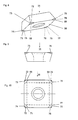
- Insert body 35 as indexable insert 36 has body 37 the indexable insert 36 two opposite one another End faces 38, 39 and four at right angles to one another arranged side surfaces 40, 41, 42, 43.
- the side faces 40, 41, 42, 43 go over the connecting edges at the corner areas 44, 45, 46, 47 one inside the other and on the peripheral edges 48 to 55 in the end faces 38, 39 over.
- the body 37 of the indexable insert 36 has a truncated pyramid Basic shape and the lower peripheral edges 48, 49, 50, 51 are designed as main cutting edges 56, 57, 58, 59.
- each side surface then forms 40, 41, 42, 43 a rake face 40a, 41a, 42a, 43a.
- the cutting inserts described are preferably cubic Boron nitride or polycrystalline cubic boron nitride or a layer of polycrystalline diamond coated. Possibly. an outer layer of aluminum oxide can be applied.
- the relevant coatings are described in detail in the DE 41 26 851 al and DE 41 26 852 A1 described what is hereby expressly referred to.
- inlays from cubic Boron nitride or polycrystalline diamond based on substrate body to be soldered to use. Such inlays will be e.g. in VDI-Z., Vol. 129 (1987) No. 2 - February, pages 64 to 69.
Claims (14)
- Procédé de fraisage pour l'usinage par enlèvement de copeaux de contours cylindriques, de contours cylindriques sur une pièce tournant autour de son axe longitudinal, qui sont disposés de façon excentrique, de paliers de levage de vilebrequin serrés de manière centrique, au moyen d'outils rotatifs, entraínables, dans le cas duquel un contour fini est réalisé de telle manière que celui-ci présente soit, avec une qualité suffisante de surface, des dimensions finales soit encore une surmesure pour effectuer un travail de finissage tel que la rectification ou le finissage, les outils munis d'inserts de coupe selon la revendication 9, en particulier de plaquettes réversibles, étant mis en prise l'un après l'autre ou aussi simultanément avec la pièce pour la réalisation du contour fini,
caractérisé par le fait que l'usinage par enlèvement de copeaux est effectué avec une fraiseque du moins quelques-uns des inserts de coupe présentent un angle positif de coupe et sont guidés, par rapport à la pièce, à un angle effectif de coupe qui est compris entre -5° et +15° et/ou à un angle de coupe vers l'arrière d'outil (γp) > 0, angle axial de coupe, de préférence ≤ 10°.a) avec une vitesse de coupe supérieure à 160 m/min,b) avec des épaisseurs de coupe comprises entre 0,1 mm et 0,3 mm, de préférence entre 0,2 mm et 0,25 mm, etc) avec une faible longueur de l'arc de coupe de l'outil portant des inserts de coupe, - Procédé selon la revendication 1, caractérisé par le fait que la longueur de l'arc de coupe, c'est-à-dire la longueur de l'outil, qui est en prise avec les inserts de coupe correspondants, par rapport à sa périphérie totale, est comprise seulement entre un dixième et un millième de la périphérie totale.
- Procédé selon l'une des revendications 1 ou 2, caractérisé par le fait que, pour les deux opérations de coupe du moins, on utilise deux outils du moins l'un après l'autre qui présentent l'un par rapport à l'autre des types différents d'inserts de coupe, un ou plusieurs types d'inserts de coupe pouvant être utilisés sur chaque outil, et/ou que l'opération de coupe pour la réalisation du contour fini est effectuée en deux opérations de coupe du moins durant lesquelles des processus différents d'usinage ou également des processus pareils d'usinage sont effectués, de préférence, dans une première étape, du moins une flasque de palier de levage étant usinée et, dans une deuxième étape, du moins un palier de levage étant usiné pour produire le diamètre du tourillon et la sous-coupe.
- Procédé selon l'une des revendications 1 à 3, caractérisé par le fait que, dans une première étape, tous les contours droits et, dans une deuxième étape, tous les contours gauches du profil, c'est-à-dire du contour fini sont fabriqués, et/ou qu'une étape d'usinage est réalisée en tant que fraisage rotatif orthogonal.
- Dispositif pour la mise en oeuvre du procédé selon l'une des revendications 1 à 4, comprenant du moins un outil muni d'inserts de coupe, caractérisé par le fait que le dispositif (100) présente du moins deux outils (15, 16) pourvus d'inserts de coupe selon la revendication 9, chaque outil (15, 16) étant une fraise qui peut être déplacée avec des vitesses de coupe supérieures à 160 m/min et qui présente des inserts de coupe (34, 35) qui possèdent un angle de coupe positif et peuvent être guidés, par rapport à la pièce, à un angle de coupe effectif compris entre - 5° et +15° et à un angle de coupe vers l'arrière d'outil (γp) > 0.
- Dispositif selon la revendication 5, caractérisé par le fait que les inserts de coupe (34, 35) sont formés et disposés de telle manière que la moitié à peu près du contour fini du tourillon peut être produite respectivement dans une opération de plongée.
- Dispositif selon la revendication 5 ou 6, caractérisé par le fait qu'une fraise à disque et/ou une fraise rotative orthogonale est utilisée comme outil.
- Dispositif selon l'une des revendications 5 à 7, caractérisé par le fait que, pour un outil (21, 22) du moins, on prévoit un support avec deux chariots (25, 26; 27, 29) qui permettent que l'outil (21, 22) peut être déplacé dans deux directions verticales l'une à l'autre.
- Insert de coupe (35) destiné au fraisage, avec une face de coupe (38) pour l'essentiel rectangulaire qui est limitée sur la périphérie par des tranchants principaux respectifs (56 à 59), et avec des faces de dépouille (40 à 43) disposées à un angle positif de taillant, dont les arêtes respectivement communes (44 à 47) forment des tranchants secondaires (60, 61, 62, 63), et avec un angle de coupe positif, caractérisé par le fait que la face de coupe (38) présente, dans la zone des tranchants principaux voisins formant un coin de coupe, un aplatissement ou une partie reculée (68, 69, 70, 71) qui s'étend dans la zone des deux tranchants principaux voisins, et que, dans le cas d'un montage tangentiel de l'insert de coupe, un angle compris entre 75° et 95°, de préférence entre 85° et 95°, est réglé entre la face effective de coupe (40a, 41a, 42a, 43a) et la face effective de dépouille (38), de sorte qu'il y a un angle de coupe effectif qui est compris entre -5° et +15°, de préférence entre -5° et +5°.
- Insert de coupe selon la revendication 9, caractérisé par le fait que, dû à l'aplatissement ou à la partie reculée (68, 69, 70, 71), le coin (64, 65, 66, 67) du corps de coupe est disposé de façon reculée par rapport au tranchant principal (56, 57, 58, 59) et/ou que le coin (64, 65, 66, 67) du corps de coupe est reculé d'à peu près 0,05 mm à 1 mm par rapport au tranchant principal (56, 57, 58, 59).
- Insert de coupe selon l'une des revendications 9 ou 10, caractérisé par le fait que l'aplatissement ou la partie reculée (68, 69, 70, 71) est formé en tant que surface plane ou courbée ou à plusieurs parties, et/ou que l'aplatissement ou la partie reculée (68, 69, 70, 71) s'étend au maximum sur, la demi-longueur du tranchant principal et jusqu'au coin du corps de coupe, de préférence le long d'un quart du tranchant principal.
- Insert de coupe selon l'une des revendications 9 à 11, caractérisé par le fait que du moins une face latérale (40, 41, 42, 43) présente, dans la zone d'un coin respectivement associé du corps de coupe, du moins un aplatissement ou une partie reculée (72 à 79) en tant que surface d'appui, et/ou que l'aplatissement ou la partie reculée (68 à 79) sur le front (38, 39) et/ou sur la face latérale (40, 41, 42, 43) est formé en tant que surface plane, courbée ou à plusieurs parties.
- Insert de coupe selon l'une des revendications 9 à 12, caractérisé par le fait que le coin (64, 65, 66, 67) du corps de coupe est réalisé en tant que calotte sphérique, cône ou pyramide ou comme tronc de cône ou de pyramide, et/ou qu'un ou plusieurs éléments à former le copeau sont disposés sur la face effective de coupe (40a, 41a, 42a, 43a).
- Insert de coupe selon l'une des revendications 9 à 13, caractérisé par le fait que l'insert de coupe est revêtu d'un nitrure de bore cubique (CBN) et/ou de diamant polycristallin (PKD) et/ou est pourvu d'un insert (inlay) en CBN ou PKD, et/ou qu'une couche en Al2O3 est appliquée en tant que couche la plus extérieure.
Applications Claiming Priority (7)
| Application Number | Priority Date | Filing Date | Title |
|---|---|---|---|
| DE19519951 | 1995-06-06 | ||
| DE19520058A DE19520058A1 (de) | 1995-06-06 | 1995-06-06 | Schneideinsatz |
| DE19519951A DE19519951A1 (de) | 1995-06-06 | 1995-06-06 | Verfahren zur spanenden Bearbeitung von zylindrischen Konturen, Vorrichtung zur Durchführung des Verfahrens und Schneideinsatz hierzu |
| DE19520058 | 1995-06-06 | ||
| DE1995146196 DE19546196A1 (de) | 1995-12-11 | 1995-12-11 | Verfahren zur spanenden Bearbeitung von zylindrischen Konturen, Vorrichtung zur Durchführung des Verfahrens und Schneideinsatz hierzu |
| DE19546196 | 1995-12-11 | ||
| PCT/DE1996/000947 WO1996039269A1 (fr) | 1995-06-06 | 1996-05-23 | Procede d'usinage par enlevement de copeaux de contours cylindriques, dispositif de mise en ×uvre du procede et plaquette de coupe associee |
Publications (2)
| Publication Number | Publication Date |
|---|---|
| EP0830228A1 EP0830228A1 (fr) | 1998-03-25 |
| EP0830228B1 true EP0830228B1 (fr) | 2000-07-26 |
Family
ID=27215161
Family Applications (1)
| Application Number | Title | Priority Date | Filing Date |
|---|---|---|---|
| EP96919612A Revoked EP0830228B1 (fr) | 1995-06-06 | 1996-05-23 | Procede d'usinage par enlevement de copeaux de contours cylindriques, dispositif de mise en uvre du procede et plaquette de coupe associee |
Country Status (7)
| Country | Link |
|---|---|
| US (2) | US6374472B1 (fr) |
| EP (1) | EP0830228B1 (fr) |
| JP (1) | JP3950476B2 (fr) |
| AT (1) | ATE194935T1 (fr) |
| DE (1) | DE59605652D1 (fr) |
| ES (1) | ES2148770T3 (fr) |
| WO (1) | WO1996039269A1 (fr) |
Cited By (4)
| Publication number | Priority date | Publication date | Assignee | Title |
|---|---|---|---|---|
| WO2007006275A1 (fr) * | 2005-07-11 | 2007-01-18 | Kennametal Widia Produktions Gmbh & Co. Kg | Procede d'usinage de vilebrequins par enlevement de copeaux et dispositif permettant la mise en oeuvre dudit procede |
| WO2007016890A1 (fr) * | 2005-08-08 | 2007-02-15 | Kennametal Widia Produktions Gmbh & Co. Kg | Plaquette de coupe |
| DE102005050210B4 (de) * | 2005-10-20 | 2010-11-11 | Kennametal Widia Produktions Gmbh & Co. Kg | Schneideinsatz und Fräser |
| DE10333621B4 (de) * | 2003-07-09 | 2016-02-25 | Kennametal Widia Produktions Gmbh & Co. Kg | Schneideinsatz |
Families Citing this family (27)
| Publication number | Priority date | Publication date | Assignee | Title |
|---|---|---|---|---|
| DE19626627C1 (de) * | 1996-07-02 | 1997-09-18 | Boehringer Werkzeugmaschinen | Fräsmaschine |
| DE19626608B4 (de) * | 1996-07-02 | 2004-11-11 | Boehringer Werkzeugmaschinen Gmbh | Verfahren zur spanenden Bearbeitung |
| DE19626609C2 (de) * | 1996-07-02 | 2000-03-09 | Boehringer Werkzeugmaschinen | Mehrfachfräsen an Kurbelwellen |
| DE19654815A1 (de) * | 1996-12-31 | 1998-07-02 | Heller Geb Gmbh Maschf | Wendeschneidwerkzeug |
| DE19722454A1 (de) * | 1997-05-28 | 1998-12-10 | Boehringer Werkzeugmaschinen | Verfahren zum Steuern der Bearbeitung eines Werkstückes |
| DE19739366A1 (de) | 1997-09-09 | 1999-03-18 | Kennametal Inc | Scheibenfräser und dafür geeignete Wendeplatte |
| DE19743971B4 (de) * | 1997-10-06 | 2008-06-19 | Widia Gmbh | Schneideinsatz, Fräswerkzeug und Verwendung des Fräswerkzeuges |
| DE19749940C5 (de) | 1997-11-11 | 2010-05-20 | Boehringer Werkzeugmaschinen Gmbh | Verfahren zur verwendungsfähigen Fertigbearbeitung von Kurbelwellen |
| JP3472752B2 (ja) * | 2000-08-03 | 2003-12-02 | 住友電気工業株式会社 | スローアウェイチップ及びそれを用いたピンミラーカッタ |
| IL141089A (en) * | 2001-01-25 | 2006-08-20 | Amir Satran | Put a spin |
| DE10144542C1 (de) | 2001-09-10 | 2003-06-05 | Walter Ag | Schneidplatte und Fräswerkzeug |
| DE10235957B4 (de) * | 2002-08-06 | 2005-01-20 | Hegenscheidt-Mfd Gmbh & Co. Kg | Verfahren zum Fertigbearbeiten von Kurbelwellen für Kraftfahrzeugmotoren |
| US7402010B2 (en) | 2002-08-13 | 2008-07-22 | Kennametal Widia Gmbh & Co. Kg | Disk-shaped or strip-shaped tool |
| BRPI0412406A (pt) * | 2003-07-09 | 2006-09-05 | Kennametal Widia Prod Gmbh | inserto de corte |
| DE202004002491U1 (de) * | 2004-02-17 | 2005-08-18 | Kennametal Inc. | Schneidplatte, insbesondere für ein Ausdrehwerkzeug |
| DE102004022360B4 (de) | 2004-04-30 | 2018-05-09 | Gebr. Heller Maschinenfabrik Gmbh | Verfahren zur Feinbearbeitung, vorzugsweise zur Feinstschlichtbearbeitung, von Werkstücken vorzugsweise von Kurbelwellen |
| SE529146C2 (sv) * | 2005-02-22 | 2007-05-15 | Seco Tools Ab | Skär för svarvning där fasvinkeln vid hörnet uppvisar ett minimum |
| SE530153C2 (sv) * | 2005-02-22 | 2008-03-11 | Seco Tools Ab | Skär för svarvning med ett perifert land av konstant bredd |
| DE102005025815A1 (de) * | 2005-06-02 | 2006-12-07 | Kennametal Widia Produktions Gmbh & Co. Kg | Schneideinsatz, insbesondere zur Kurbelwellenbearbeitung |
| EP1907156B1 (fr) | 2005-07-22 | 2015-07-15 | Gebr. Heller Maschinenfabrik GmbH | Procede d'usinage de precision d'arbres-manivelles et centre d'usinage correspondant |
| AT503333B1 (de) | 2006-03-07 | 2008-06-15 | Boehlerit Gmbh & Co Kg | Wendeschneidplatte für fräswerkzeuge |
| DE102011089654B4 (de) * | 2011-12-22 | 2015-01-29 | Erwin Junker Maschinenfabrik Gmbh | Verfahren zur drehbearbeitung von planschultern an den wangen einer kurbelwelle, verwendung des verfahrens zur komplettbearbeitung von kurbelwellenrohlingen sowie kurbelwellen-drehmaschine zur drehbearbeitung der planschultern |
| DE102015102044A1 (de) * | 2015-02-12 | 2016-08-18 | Kennametal Inc. | Fräswerkzeug und Schneideinsatz für ein solches Fräswerkzeug |
| USD777230S1 (en) | 2015-07-16 | 2017-01-24 | Kennametal Inc | Double-sided tangential cutting insert |
| US9981323B2 (en) | 2015-07-16 | 2018-05-29 | Kennametal Inc. | Double-sided tangential cutting insert and cutting tool system using the same |
| USD778330S1 (en) | 2015-07-16 | 2017-02-07 | Kennametal Inc. | Double-sided tangential cutting insert |
| CZ306280B6 (cs) * | 2015-09-23 | 2016-11-09 | Západočeská Univerzita V Plzni | Zařízení pro kalibraci upnutého obrobku |
Family Cites Families (42)
| Publication number | Priority date | Publication date | Assignee | Title |
|---|---|---|---|---|
| US2290324A (en) * | 1941-01-06 | 1942-07-21 | Rk Leblond Machine Tool Co | Method of machining crankshafts |
| US3279034A (en) * | 1964-12-17 | 1966-10-18 | Ingersoll Milling Machine Co | Indexable cutter blade |
| US3279035A (en) * | 1964-12-18 | 1966-10-18 | Ingersoll Milling Machine Co | Indexable cutter blade |
| AT286067B (de) | 1968-06-21 | 1970-11-25 | Skoda Np | Fraesmaschine fuer kurbelwellen od. dgl |
| DE2559468B2 (de) * | 1975-11-14 | 1978-04-20 | Gebr. Boehringer Gmbh, 7320 Goeppingen | Kurbelwellenfräsmaschine |
| JPS5267885A (en) * | 1975-12-04 | 1977-06-04 | Komatsu Ltd | Control unit for crank shaft mirror |
| DE2618093A1 (de) * | 1976-04-24 | 1978-03-16 | Heller Geb Gmbh Maschf | Kurbelwellenfraesmaschine |
| SU642093A1 (ru) * | 1976-05-25 | 1979-01-15 | Закавказский Филиал Экспериментального Научно-Исследовательского Института Металлорежущих Станков | Способ обработки шатунных шеек коленчатых валов |
| AT345061B (de) * | 1977-04-18 | 1978-08-25 | Gfm Fertigungstechnik | Verfahren und fraesmaschine zum fraesen der kurbelzapfen von mehrfach, vorzugsweise vierfach gekroepften kurbelwellen |
| AT351336B (de) * | 1978-04-18 | 1979-07-25 | Gfm Fertigungstechnik | Werkzeug zum wirbeln runder profile |
| AT353073B (de) * | 1978-04-18 | 1979-10-25 | Gfm Fertigungstechnik | Verfahren zum bearbeiten von kurbelwellen |
| AT358361B (de) * | 1979-03-08 | 1980-09-10 | Gfm Fertigungstechnik | Verfahren zum bearbeiten von mehrfach gekroepften kurbelwellen |
| DE3026476A1 (de) | 1980-07-12 | 1982-02-04 | Hans 7335 Salach Müller | Verfahren und vorrichtung zum bohren bzw. aufbohren von loechern in werkstuecken |
| US4433948A (en) * | 1981-11-12 | 1984-02-28 | Kabushiki Kaisha Komatsu Seisakusho | Cutter for a crankshaft milling machine |
| DE3213740A1 (de) * | 1982-04-14 | 1983-12-15 | Oerlikon-Boehringer GmbH, 7320 Göppingen | Wirbelgeraet |
| DE8217873U1 (de) * | 1982-06-22 | 1984-04-05 | Gebr. Heller Maschinenfabrik GmbH, 7440 Nürtingen | Kurbelwellenfraesmaschine |
| US4624610A (en) * | 1983-06-27 | 1986-11-25 | J. D. Phillips Corporation | Milling machine |
| US4597695A (en) * | 1985-03-11 | 1986-07-01 | Ingersoll Cutting Tool Company | Face milling apparatus with eight-edged insert |
| DE3807165A1 (de) | 1987-03-04 | 1988-09-15 | Mitsubishi Metal Corp | Umstellbarer schneideinsatz |
| US4790698A (en) * | 1987-05-13 | 1988-12-13 | Cm Systems, Incorporated | Monotonic cutting machine |
| US5037248A (en) * | 1987-05-13 | 1991-08-06 | Ingersoll Cm Systems Inc. | Cutter for monotonic cutting machine |
| JP2512995B2 (ja) * | 1988-06-20 | 1996-07-03 | 三菱マテリアル株式会社 | スロ―アウエイチップ |
| ATE100366T1 (de) * | 1988-12-02 | 1994-02-15 | Gen Motors Corp | Scheibenfoermigen fraeser mit verbessertem schneidkoerpen. |
| DE4013327C2 (de) * | 1990-04-26 | 1999-12-30 | Werner Hermann Wera Werke | Maschine zur spanenden Metallbearbeitung |
| US5244318A (en) | 1990-07-04 | 1993-09-14 | Mitsubishi Materials Corporation | Throwaway insert and cutting tool therefor |
| EP0505574B1 (fr) * | 1990-10-15 | 1997-01-02 | Mitsubishi Materials Corporation | Outil de coupe et tete de coupe jetables |
| DE4119162C1 (fr) * | 1991-06-11 | 1992-05-21 | Gebr. Heller Maschinenfabrik Gmbh, 7440 Nuertingen, De | |
| DE4135681C3 (de) | 1991-10-30 | 1999-02-11 | Heller Geb Gmbh Maschf | Verfahren zur spanenden Bearbeitung rotationssymmetrischer Werkstückflächen, insbesondere von Kurbelwellen, sowie Werkzeug zur Durchführung eines solchen Verfahrens |
| US5460464A (en) | 1992-05-07 | 1995-10-24 | Mitsubishi Materials Corporation | Cutting insert |
| JPH068105A (ja) * | 1992-06-29 | 1994-01-18 | Komatsu Ltd | 円筒形状加工装置 |
| JP3246961B2 (ja) * | 1992-11-05 | 2002-01-15 | 株式会社小松製作所 | クランクシャフトミラーの制御装置 |
| JPH06218618A (ja) | 1993-01-21 | 1994-08-09 | Mitsubishi Materials Corp | スローアウェイチップ |
| SE500721C2 (sv) * | 1993-01-27 | 1994-08-15 | Sandvik Ab | Skär med vriden spånyta |
| JP3433758B2 (ja) * | 1993-03-31 | 2003-08-04 | 株式会社小松製作所 | クランクシャフトの加工方法 |
| JP3166022B2 (ja) | 1993-12-28 | 2001-05-14 | 三菱マテリアル株式会社 | スローアウェイチップおよびその製造方法 |
| FR2716638B1 (fr) * | 1994-02-25 | 1996-04-26 | Jupiter Const Electr | Procédé de fraisage d'au moins une région localisée d'une pièce. |
| DE4411475A1 (de) * | 1994-04-01 | 1995-10-05 | Walter Ag | Schneidplatte, insbesondere Wendeschneidplatte |
| EP0792201B1 (fr) * | 1994-11-19 | 2000-01-12 | KOMET Präzisionswerkzeuge Robert Breuning GmbH | Plaquette de coupe pour usinage de pieces par enlevement de copeaux |
| DE4446475C2 (de) * | 1994-12-23 | 2000-06-21 | Boehringer Werkzeugmaschinen | Verfahren und Maschine zum Bearbeiten von Werkstücken |
| US5707187A (en) * | 1995-06-07 | 1998-01-13 | Ingersoll, Cm Systems, Inc. | Crankshaft milling apparatus |
| JP3731763B2 (ja) * | 1995-11-13 | 2006-01-05 | コマツ工機株式会社 | クランクシャフトミラーの切粉飛散防止装置 |
| DE19900857A1 (de) * | 1998-01-22 | 1999-07-29 | Mitsubishi Materials Corp | Befestigungsmechanismus für einen Stiftspiegelfräser |
-
1996
- 1996-05-23 US US08/973,289 patent/US6374472B1/en not_active Expired - Lifetime
- 1996-05-23 EP EP96919612A patent/EP0830228B1/fr not_active Revoked
- 1996-05-23 ES ES96919612T patent/ES2148770T3/es not_active Expired - Lifetime
- 1996-05-23 JP JP50007297A patent/JP3950476B2/ja not_active Expired - Lifetime
- 1996-05-23 WO PCT/DE1996/000947 patent/WO1996039269A1/fr not_active Application Discontinuation
- 1996-05-23 DE DE59605652T patent/DE59605652D1/de not_active Revoked
- 1996-05-23 AT AT96919612T patent/ATE194935T1/de not_active IP Right Cessation
-
1998
- 1998-12-07 US US09/206,841 patent/US6146063A/en not_active Expired - Lifetime
Cited By (6)
| Publication number | Priority date | Publication date | Assignee | Title |
|---|---|---|---|---|
| DE10333621B4 (de) * | 2003-07-09 | 2016-02-25 | Kennametal Widia Produktions Gmbh & Co. Kg | Schneideinsatz |
| WO2007006275A1 (fr) * | 2005-07-11 | 2007-01-18 | Kennametal Widia Produktions Gmbh & Co. Kg | Procede d'usinage de vilebrequins par enlevement de copeaux et dispositif permettant la mise en oeuvre dudit procede |
| DE102005038021A1 (de) * | 2005-07-11 | 2007-01-25 | Kennametal Widia Produktions Gmbh & Co. Kg | Verfahren zur zerspanenden Bearbeitung von Kurbelwellen und Vorrichtung zur Durchführung dieses Verfahrens |
| DE102005038021B4 (de) * | 2005-07-11 | 2016-07-21 | Kennametal Widia Produktions Gmbh & Co. Kg | Verfahren zur zerspanenden Bearbeitung von Kurbelwellen und Vorrichtung zur Durchführung dieses Verfahrens |
| WO2007016890A1 (fr) * | 2005-08-08 | 2007-02-15 | Kennametal Widia Produktions Gmbh & Co. Kg | Plaquette de coupe |
| DE102005050210B4 (de) * | 2005-10-20 | 2010-11-11 | Kennametal Widia Produktions Gmbh & Co. Kg | Schneideinsatz und Fräser |
Also Published As
| Publication number | Publication date |
|---|---|
| US6374472B1 (en) | 2002-04-23 |
| DE59605652D1 (de) | 2000-08-31 |
| JP3950476B2 (ja) | 2007-08-01 |
| JPH11506055A (ja) | 1999-06-02 |
| US6146063A (en) | 2000-11-14 |
| ATE194935T1 (de) | 2000-08-15 |
| EP0830228A1 (fr) | 1998-03-25 |
| ES2148770T3 (es) | 2000-10-16 |
| WO1996039269A1 (fr) | 1996-12-12 |
Similar Documents
| Publication | Publication Date | Title |
|---|---|---|
| EP0830228B1 (fr) | Procede d'usinage par enlevement de copeaux de contours cylindriques, dispositif de mise en uvre du procede et plaquette de coupe associee | |
| EP1030754B1 (fr) | Fraisage haute vitesse + tournage / brochage par tournage/ tournage - brochage par tournage | |
| EP1317985B1 (fr) | Alesoir | |
| EP2367656B2 (fr) | Machine-outil et procédé de fabrication de dentures | |
| EP0700744B1 (fr) | Fabrication et fraise de rainures profondes, spécialement pour roteur de génératrices et turbines | |
| EP0912284B2 (fr) | Fraiseuse | |
| EP0417446B1 (fr) | Usinage de vilebrequin en 3 phases | |
| DE102011079900A1 (de) | Verfahren und Bearbeitungsanlage zum Feinbearbeiten einer Kurbelwellenlagerbohrung | |
| WO2008012254A2 (fr) | Fraiseuse de vilebrequins | |
| EP1286802B1 (fr) | Fraise trois tailles | |
| EP1422005B1 (fr) | Procédé et dispositif pour l'usinage du bord de lentilles ophtalmiques en plastique | |
| EP0868242B1 (fr) | Procede et dispositif de fraisage par rotation | |
| EP1097772A2 (fr) | Génération de structures périodiques sur des pièces ayant une symétrie de révolution | |
| EP0485546B1 (fr) | Garniture de coupe pour outils | |
| WO2006002862A1 (fr) | Outil et dispositif pour usiner des pieces a usiner | |
| EP0912283B1 (fr) | Fraisage a grande vitesse | |
| EP0841116B1 (fr) | Méthode de travail de surfaces de pièces symétriques en rotation et outil employé | |
| EP0912282B2 (fr) | Fraisages multiples sur vilebrequins | |
| DE3909643C2 (de) | Mehrschneidenwerkzeugkopf zur spanabhebenden Vor- und Feinbearbeitung mit kreisförmiger Schnittbewegung | |
| DE19520058A1 (de) | Schneideinsatz | |
| DE19546196A1 (de) | Verfahren zur spanenden Bearbeitung von zylindrischen Konturen, Vorrichtung zur Durchführung des Verfahrens und Schneideinsatz hierzu | |
| DE19519951A1 (de) | Verfahren zur spanenden Bearbeitung von zylindrischen Konturen, Vorrichtung zur Durchführung des Verfahrens und Schneideinsatz hierzu | |
| EP1977845A2 (fr) | Fraise dotée de plusieurs plaques de coupe |
Legal Events
| Date | Code | Title | Description |
|---|---|---|---|
| PUAI | Public reference made under article 153(3) epc to a published international application that has entered the european phase |
Free format text: ORIGINAL CODE: 0009012 |
|
| 17P | Request for examination filed |
Effective date: 19971208 |
|
| AK | Designated contracting states |
Kind code of ref document: A1 Designated state(s): AT BE CH DE DK ES FI FR GB GR IE IT LI LU MC NL PT SE |
|
| 17Q | First examination report despatched |
Effective date: 19980814 |
|
| GRAG | Despatch of communication of intention to grant |
Free format text: ORIGINAL CODE: EPIDOS AGRA |
|
| GRAG | Despatch of communication of intention to grant |
Free format text: ORIGINAL CODE: EPIDOS AGRA |
|
| GRAH | Despatch of communication of intention to grant a patent |
Free format text: ORIGINAL CODE: EPIDOS IGRA |
|
| GRAH | Despatch of communication of intention to grant a patent |
Free format text: ORIGINAL CODE: EPIDOS IGRA |
|
| GRAA | (expected) grant |
Free format text: ORIGINAL CODE: 0009210 |
|
| AK | Designated contracting states |
Kind code of ref document: B1 Designated state(s): AT BE CH DE DK ES FI FR GB IT LI LU NL PT SE |
|
| PG25 | Lapsed in a contracting state [announced via postgrant information from national office to epo] |
Ref country code: NL Free format text: LAPSE BECAUSE OF FAILURE TO SUBMIT A TRANSLATION OF THE DESCRIPTION OR TO PAY THE FEE WITHIN THE PRESCRIBED TIME-LIMIT Effective date: 20000726 Ref country code: FI Free format text: LAPSE BECAUSE OF FAILURE TO SUBMIT A TRANSLATION OF THE DESCRIPTION OR TO PAY THE FEE WITHIN THE PRESCRIBED TIME-LIMIT Effective date: 20000726 |
|
| REF | Corresponds to: |
Ref document number: 194935 Country of ref document: AT Date of ref document: 20000815 Kind code of ref document: T |
|
| REG | Reference to a national code |
Ref country code: CH Ref legal event code: EP |
|
| GBT | Gb: translation of ep patent filed (gb section 77(6)(a)/1977) |
Effective date: 20000726 |
|
| ET | Fr: translation filed | ||
| REF | Corresponds to: |
Ref document number: 59605652 Country of ref document: DE Date of ref document: 20000831 |
|
| ITF | It: translation for a ep patent filed |
Owner name: STUDIO JAUMANN P. & C. S.N.C. |
|
| REG | Reference to a national code |
Ref country code: ES Ref legal event code: FG2A Ref document number: 2148770 Country of ref document: ES Kind code of ref document: T3 |
|
| PG25 | Lapsed in a contracting state [announced via postgrant information from national office to epo] |
Ref country code: SE Free format text: LAPSE BECAUSE OF FAILURE TO SUBMIT A TRANSLATION OF THE DESCRIPTION OR TO PAY THE FEE WITHIN THE PRESCRIBED TIME-LIMIT Effective date: 20001026 Ref country code: PT Free format text: LAPSE BECAUSE OF FAILURE TO SUBMIT A TRANSLATION OF THE DESCRIPTION OR TO PAY THE FEE WITHIN THE PRESCRIBED TIME-LIMIT Effective date: 20001026 Ref country code: DK Free format text: LAPSE BECAUSE OF FAILURE TO SUBMIT A TRANSLATION OF THE DESCRIPTION OR TO PAY THE FEE WITHIN THE PRESCRIBED TIME-LIMIT Effective date: 20001026 |
|
| NLV1 | Nl: lapsed or annulled due to failure to fulfill the requirements of art. 29p and 29m of the patents act | ||
| PLBQ | Unpublished change to opponent data |
Free format text: ORIGINAL CODE: EPIDOS OPPO |
|
| PLBI | Opposition filed |
Free format text: ORIGINAL CODE: 0009260 |
|
| PLBQ | Unpublished change to opponent data |
Free format text: ORIGINAL CODE: EPIDOS OPPO |
|
| PLBI | Opposition filed |
Free format text: ORIGINAL CODE: 0009260 |
|
| PG25 | Lapsed in a contracting state [announced via postgrant information from national office to epo] |
Ref country code: LU Free format text: LAPSE BECAUSE OF NON-PAYMENT OF DUE FEES Effective date: 20010523 |
|
| PLBF | Reply of patent proprietor to notice(s) of opposition |
Free format text: ORIGINAL CODE: EPIDOS OBSO |
|
| PG25 | Lapsed in a contracting state [announced via postgrant information from national office to epo] |
Ref country code: BE Free format text: LAPSE BECAUSE OF NON-PAYMENT OF DUE FEES Effective date: 20010531 |
|
| 26 | Opposition filed |
Opponent name: SANDVIK AB Effective date: 20010425 |
|
| PG25 | Lapsed in a contracting state [announced via postgrant information from national office to epo] |
Ref country code: LI Free format text: LAPSE BECAUSE OF NON-PAYMENT OF DUE FEES Effective date: 20010622 Ref country code: CH Free format text: LAPSE BECAUSE OF NON-PAYMENT OF DUE FEES Effective date: 20010622 |
|
| 26 | Opposition filed |
Opponent name: GEBR. HELLER MASCHINENFABRIK GMBH Effective date: 20010425 Opponent name: WALTER AG Effective date: 20010426 Opponent name: SANDVIK AB Effective date: 20010425 |
|
| PLBF | Reply of patent proprietor to notice(s) of opposition |
Free format text: ORIGINAL CODE: EPIDOS OBSO |
|
| BERE | Be: lapsed |
Owner name: WIDIA G.M.B.H. Effective date: 20010531 |
|
| REG | Reference to a national code |
Ref country code: GB Ref legal event code: IF02 |
|
| REG | Reference to a national code |
Ref country code: CH Ref legal event code: PL |
|
| RDAF | Communication despatched that patent is revoked |
Free format text: ORIGINAL CODE: EPIDOSNREV1 |
|
| APBP | Date of receipt of notice of appeal recorded |
Free format text: ORIGINAL CODE: EPIDOSNNOA2O |
|
| APBQ | Date of receipt of statement of grounds of appeal recorded |
Free format text: ORIGINAL CODE: EPIDOSNNOA3O |
|
| APAA | Appeal reference recorded |
Free format text: ORIGINAL CODE: EPIDOS REFN |
|
| APAH | Appeal reference modified |
Free format text: ORIGINAL CODE: EPIDOSCREFNO |
|
| PGFP | Annual fee paid to national office [announced via postgrant information from national office to epo] |
Ref country code: AT Payment date: 20060515 Year of fee payment: 11 |
|
| PGFP | Annual fee paid to national office [announced via postgrant information from national office to epo] |
Ref country code: FR Payment date: 20060519 Year of fee payment: 11 |
|
| PGFP | Annual fee paid to national office [announced via postgrant information from national office to epo] |
Ref country code: GB Payment date: 20060522 Year of fee payment: 11 |
|
| PGFP | Annual fee paid to national office [announced via postgrant information from national office to epo] |
Ref country code: ES Payment date: 20060530 Year of fee payment: 11 Ref country code: DE Payment date: 20060530 Year of fee payment: 11 |
|
| PGFP | Annual fee paid to national office [announced via postgrant information from national office to epo] |
Ref country code: IT Payment date: 20060531 Year of fee payment: 11 |
|
| APBU | Appeal procedure closed |
Free format text: ORIGINAL CODE: EPIDOSNNOA9O |
|
| RDAG | Patent revoked |
Free format text: ORIGINAL CODE: 0009271 |
|
| STAA | Information on the status of an ep patent application or granted ep patent |
Free format text: STATUS: PATENT REVOKED |
|
| 27W | Patent revoked |
Effective date: 20061127 |
|
| GBPR | Gb: patent revoked under art. 102 of the ep convention designating the uk as contracting state |
Free format text: 20061127 |