EP2378336B1 - Retrofokus Zoom Objektiv mit fünf Linsengruppen - Google Patents
Retrofokus Zoom Objektiv mit fünf Linsengruppen Download PDFInfo
- Publication number
- EP2378336B1 EP2378336B1 EP11005734.6A EP11005734A EP2378336B1 EP 2378336 B1 EP2378336 B1 EP 2378336B1 EP 11005734 A EP11005734 A EP 11005734A EP 2378336 B1 EP2378336 B1 EP 2378336B1
- Authority
- EP
- European Patent Office
- Prior art keywords
- lens
- lens unit
- zoom
- refractive power
- unit
- Prior art date
- Legal status (The legal status is an assumption and is not a legal conclusion. Google has not performed a legal analysis and makes no representation as to the accuracy of the status listed.)
- Active
Links
- 230000003287 optical effect Effects 0.000 claims description 33
- 230000005499 meniscus Effects 0.000 claims description 8
- 238000006243 chemical reaction Methods 0.000 claims description 4
- 230000004075 alteration Effects 0.000 description 28
- 239000004973 liquid crystal related substance Substances 0.000 description 15
- 238000010586 diagram Methods 0.000 description 7
- 239000000463 material Substances 0.000 description 5
- 230000015572 biosynthetic process Effects 0.000 description 4
- 239000011521 glass Substances 0.000 description 4
- 238000003786 synthesis reaction Methods 0.000 description 4
- 239000003086 colorant Substances 0.000 description 3
- 230000002194 synthesizing effect Effects 0.000 description 3
- 239000006117 anti-reflective coating Substances 0.000 description 2
- 238000001816 cooling Methods 0.000 description 2
- 238000006073 displacement reaction Methods 0.000 description 1
- 230000000694 effects Effects 0.000 description 1
- 238000000034 method Methods 0.000 description 1
- 238000012986 modification Methods 0.000 description 1
- 230000004048 modification Effects 0.000 description 1
- 210000001747 pupil Anatomy 0.000 description 1
- 238000000926 separation method Methods 0.000 description 1
- 230000003595 spectral effect Effects 0.000 description 1
- 238000001228 spectrum Methods 0.000 description 1
- 238000002834 transmittance Methods 0.000 description 1
- 238000011144 upstream manufacturing Methods 0.000 description 1
Images


Classifications
-
- G—PHYSICS
- G02—OPTICS
- G02B—OPTICAL ELEMENTS, SYSTEMS OR APPARATUS
- G02B13/00—Optical objectives specially designed for the purposes specified below
- G02B13/22—Telecentric objectives or lens systems
-
- G—PHYSICS
- G02—OPTICS
- G02B—OPTICAL ELEMENTS, SYSTEMS OR APPARATUS
- G02B15/00—Optical objectives with means for varying the magnification
- G02B15/14—Optical objectives with means for varying the magnification by axial movement of one or more lenses or groups of lenses relative to the image plane for continuously varying the equivalent focal length of the objective
- G02B15/145—Optical objectives with means for varying the magnification by axial movement of one or more lenses or groups of lenses relative to the image plane for continuously varying the equivalent focal length of the objective having five groups only
- G02B15/1455—Optical objectives with means for varying the magnification by axial movement of one or more lenses or groups of lenses relative to the image plane for continuously varying the equivalent focal length of the objective having five groups only the first group being negative
- G02B15/145523—Optical objectives with means for varying the magnification by axial movement of one or more lenses or groups of lenses relative to the image plane for continuously varying the equivalent focal length of the objective having five groups only the first group being negative arranged -++-+
-
- G—PHYSICS
- G02—OPTICS
- G02B—OPTICAL ELEMENTS, SYSTEMS OR APPARATUS
- G02B15/00—Optical objectives with means for varying the magnification
- G02B15/14—Optical objectives with means for varying the magnification by axial movement of one or more lenses or groups of lenses relative to the image plane for continuously varying the equivalent focal length of the objective
- G02B15/145—Optical objectives with means for varying the magnification by axial movement of one or more lenses or groups of lenses relative to the image plane for continuously varying the equivalent focal length of the objective having five groups only
- G02B15/1455—Optical objectives with means for varying the magnification by axial movement of one or more lenses or groups of lenses relative to the image plane for continuously varying the equivalent focal length of the objective having five groups only the first group being negative
- G02B15/145531—Optical objectives with means for varying the magnification by axial movement of one or more lenses or groups of lenses relative to the image plane for continuously varying the equivalent focal length of the objective having five groups only the first group being negative arranged -++++
Definitions
- the present invention relates to a zoom lens and an image projection apparatus including the zoom lens.
- the present invention relates to a zoom lens having a long back focus, providing a high level of optical performance, and suitable for a projector producing a projected image.
- a projection lens included in such a projector is desired to have such characteristics as follows.
- a typical color projector including three display devices
- light from a white light source is separated by a color separation optical system into light beams of red, green, and blue colors, which are guided to the corresponding display devices.
- the light beams ejected from the display devices are synthesized by a color synthesis optical system and are incident on a projection lens.
- a prism or the like for synthesizing the color light beams passed through the display devices, it is necessary to leave a space between the display devices and the projection lens. Therefore, it is desirable that the projection lens have a certain length of back focus.
- a pupil on the display device side (reduction conjugate side) be substantially at infinity, that is, so-called telecentricity be good.
- a zoom lens for a projector there is known a zoom lens including a first lens unit disposed closest to the enlargement conjugate side, having negative refractive power, and fixed during zooming; and a last lens unit disposed closest to the reduction conjugate side, having positive refractive power, and fixed during zooming.
- zoom lens of this type there is known a zoom lens in which at least three zoom lens units movable during zooming are disposed between the first lens unit and the last lens unit (see, e.g., US Patent No. 6,545,817 ).
- the second and third lens units disposed in this order from the enlargement conjugate side perform a primary zoom function.
- image plane variation during zooming is corrected by moving the third lens unit and other lens units that follow.
- the third lens unit is a very important lens unit for providing a high level of optical performance throughout the zoom range. Therefore, the third lens unit has at least three lens elements to improve optical performance.
- a zoom lens for a projector is desired to have a long back focus and be telecentric on the reduction conjugate side. Therefore, a lens unit of negative refractive power is disposed on the enlargement conjugate side and a lens unit of positive refractive power is disposed on the reduction conjugate side.
- the third lens unit has a greater share of zoom ratio than those of the other lens units. Accordingly, the third lens unit has refractive power greater than that of the other lens units and causes frequent occurrence of aberration variation during zooming. Moreover, due to the great refractive power of the third lens unit, a large amount of negative distortion at the wide-angle end tends to remain.
- zoom lens for a projector it is important to set an appropriate lens configuration so as to ensure a predetermined zoom ratio, effectively correct aberration variation during zooming, and provide a high level of optical performance throughout the zoom range.
- each lens unit the second and third lens units, in particular
- the lens configuration of the third lens unit If the configuration of the second and third lens units is not appropriate, it is difficult to effectively correct distortion at the wide-angle end and provide a high level of optical performance throughout the zoom range.
- US 2007/0229967 A1 discloses a zoom lens which includes in order from a magnification side a first to fifth lens group G 1 to G 5 , wherein the first and fifth lens group is fixed during varying of a power, the first lens group executes focusing, and the second, third and fourth lens groups move interrelatedly during the varying of the power.
- the first lens group includes in order from the magnification side a glass lens having a convex surface of a negative meniscus shape directed toward the magnification side, and a plastic lens having a convex surface of a negative meniscus plane directed toward the magnification side.
- the present invention in its first aspect provides a zoom lens as specified in claims 1 to 8.
- the present invention in its second aspect provides an image projection apparatus as specified in claim 9.
- Fig. 1 illustrates a lens configuration at a wide-angle end of a zoom lens according to a first exemplary embodiment of the present invention.
- Fig. 2A and Fig. 2B are aberration diagrams of the zoom lens according to the first exemplary embodiment.
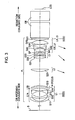
- Fig. 3 illustrates a lens configuration at a wide-angle end of a zoom lens according to a second exemplary embodiment of the present invention.
- Fig. 4A and Fig. 4B are aberration diagrams of the zoom lens according to the second exemplary embodiment.
- Fig. 5 illustrates a lens configuration at a wide-angle end of a zoom lens according to a third exemplary embodiment of the present invention.
- Fig. 6A and Fig. 6B are aberration diagrams of the zoom lens according to the third exemplary embodiment.
- Fig. 7 schematically illustrates a main part of an image projection apparatus according to an exemplary embodiment of the present invention.
- the present invention provides a zoom lens capable of effectively correcting various aberrations during zooming, offering excellent optical performance throughout the zoom range, and suitable for a projector.
- Zoom lenses according to exemplary embodiments of the present invention will now be described.
- a zoom lens according to each exemplary embodiment of the present invention includes, in order from an enlargement conjugate side to a reduction conjugate side, a first lens unit of negative refractive power, a second lens unit of positive refractive power, a third lens unit of positive refractive power, a middle lens unit having at least one lens unit, and a last lens unit of positive refractive power.
- the first lens unit is closest to the enlargement conjugate side, while the last lens unit is closest to the reduction conjugate side.
- the zoom lens of each exemplary embodiment has practically no lens unit other than the first lens unit, second lens unit, third lens unit, middle lens unit, and last lens unit.
- the enlargement conjugate side may be referred to as front (front side) or screen side.
- the reduction conjugate side may be referred to as rear (rear side) or panel side (original image side, display device side, or liquid crystal panel side).
- the middle lens unit corresponds to the fourth lens unit (having positive or negative refractive power). If the zoom lens includes six lens units (the first, second, third, fourth, fifth, and sixth lens units), the middle lens unit includes, in order from the enlargement conjugate side to the reduction conjugate side, the fourth lens unit of negative refractive power and the fifth lens unit of positive refractive power. Alternatively, when the zoom lens includes six lens units, both the fourth lens unit and the fifth lens unit may have positive refractive power.
- the second and third lens units perform a zoom function. In particular, the second lens unit performs a primary zoom function.
- the middle lens unit corrects image plane variation during zooming.
- Fig. 1 schematically illustrates a main part of an image projection apparatus (liquid crystal video projector) including a zoom lens according to a first exemplary embodiment of the present invention.
- Fig. 2A and Fig. 2B are aberration diagrams showing aberrations at the wide-angle end (short focal length side) and the telephoto end (long focal length side), respectively, of the zoom lens of the first exemplary embodiment when a projection distance (from a first lens unit to a screen) is 2.1 m.
- values in numerical example 1 (described below) corresponding to the first exemplary embodiment are expressed in millimeters (mm) .
- Fig. 3 schematically illustrates a main part of an image projection apparatus including a zoom lens according to a second exemplary embodiment of the present invention.
- Fig. 4A and Fig. 4B are aberration diagrams showing aberrations at the wide-angle end and the telephoto end, respectively, of the zoom lens of the second exemplary embodiment when a projection distance is 2.1 m.
- values in numerical example 2 (described below) corresponding to the second exemplary embodiment are expressed in mm.
- Fig. 5 schematically illustrates a main part of an image projection apparatus including a zoom lens according to a third exemplary embodiment of the present invention.
- Fig. 6A and Fig. 6B are aberration diagrams showing aberrations at the wide-angle end and the telephoto end, respectively, of the zoom lens of the third exemplary embodiment when a projection distance is 2.1 m.
- values in numerical example 3 (described below) corresponding to the third exemplary embodiment are expressed in mm.
- Fig. 7 schematically illustrates a main part of an image projection apparatus according to an exemplary embodiment of the present invention.
- a zoom lens (projection lens) PL enlarges and projects an original image LCD (on a display device or liquid crystal panel) onto a screen surface S serving as a projection surface.
- an arrow under a lens unit indicates both the direction and amount of movement of the lens unit during zooming from the wide-angle end (wide end) to the telephoto end (tele-end). The greater the inclination of the arrow relative to the vertical direction, the greater the amount of movement of the lens unit from the wide-angle end to the telephoto end.
- Reference character i denotes the order of the lens unit from the enlargement conjugate side.
- Reference character Li denotes the i-th lens unit.
- Reference character L1 denotes a first lens unit of negative refractive power
- reference character L2 denotes a second lens unit of positive refractive power
- reference character L3 denotes a third lens unit of positive refractive power
- reference character LM denotes a middle lens unit including at least one lens unit
- reference character LR denotes a last lens unit of positive refractive power.
- Reference character S denotes a screen surface (projection surface, enlargement conjugate surface, or enlargement-side conjugate position)
- reference character LCD denotes an original image (projected image) on a liquid crystal panel (liquid crystal display device, reduction conjugate surface, or reduction-side conjugate position).
- the screen surface S and the original image LCD have a conjugate relationship or substantially conjugate relationship therebetween.
- the screen surface S corresponds to a conjugate point (enlargement conjugate point or front side) having a longer distance
- the original image LCD corresponds to a conjugate point (reduction conjugate point or rear side) having a shorter distance.
- the zoom lens is used as a photographing system
- the screen surface S corresponds to an object side and the original image LCD corresponds to an image side.
- Reference character GB denotes a glass block (prism) provided for optical design purposes and corresponding to a color synthesis prism, polarizing filter, color filter, and the like.
- the zoom lens PL is mounted on a projector main body (not shown) with a connecting member (not shown) interposed therebetween.
- the glass block GB and other components upstream of the zoom lens PL and adjacent to the display device LCD are contained in the projector main body.
- the zoom lenses of the first to third exemplary embodiments have F-numbers in the 1.85 to 2.65 range.
- Each of the zoom lenses projects image information (display image) onto the screen surface S at a projection distance of 2.1 m (when values in the corresponding numerical example are expressed in mm).
- a curve d represents aberration at d-line (587.6 nm)
- a curve F represents aberration at F-line (486.1 nm)
- a curve C represents aberration at C-line (656.3 nm).
- a curve S tilt of a sagittal image plane
- a curve M tilt of a meridional image plane
- F indicates an F-number
- Y indicates an image height (image height on the projected side).
- the second lens unit L2 serves as a primary zoom lens unit.
- the third lens unit L3 has refractive power smaller than that of the second lens unit L2.
- the third lens unit L3 include at least three lens elements.
- the third lens unit L3 includes, in order from the enlargement conjugate side, a positive lens element G31, a negative lens element G32, and a positive lens element G33 (two lens elements on the enlargement conjugate side constitute a cemented lens component).
- the lens configuration of the third lens unit L3 is not limited to this.
- the third lens unit L3 may include four or five lens elements. More specifically, the positive lens element G33 closest to the reduction conjugate side may be replaced with a cemented lens component formed by cementing together a positive lens element and a negative lens element. Alternatively, another positive or negative lens element may be added to the reduction conjugate side (or enlargement conjugate side) of the positive lens element G33.
- f2 is a focal length of the second lens unit L2
- f3 is a focal length of the third lens unit L3
- fw is a focal length of the entire zoom lens at the wide-angle end
- Bf is an air-conversion length of back-focus (i.e., an air-conversion length from the lens surface closest to the reduction conjugate side to the reduction conjugate position).
- air-conversion length refers to a value obtained by dividing the length of the optical path in the material by the refractive index of the material.
- Condition (1) is for appropriately defining the refractive power of the third lens unit L3.
- Condition (2) is for appropriately defining the ratio of the refractive power of the third lens unit L3 to that of the second lens unit L2.
- the refractive power of the third lens unit L3 is made smaller than that of the second lens unit L2 and thus, aberration variation during zooming is reduced.
- the refractive power of the third lens unit L3 is greater than that defined by conditions (1) and (2), the amount of movement of the third lens unit L3 during zooming is reduced and the total length of the zoom lens is reduced. However, this causes an increase in aberration variation during zooming and makes it difficult to provide a high level of optical performance throughout the zoom range.
- the refractive power of the second lens unit L2 is too small, the amount of movement of the second lens unit L2 during zooming is increased. This is undesirable in that the total length of the zoom lens is increased.
- the back focus of the zoom lens is too short. This causes less space for arranging, on the reduction conjugate side of the zoom lens, a mirror tilted to the optical axis, a prism, and the like.
- the zoom lens having a long back focus offering a high degree of telecentricity and excellent image-forming performance, and suitable for a projector.
- the zoom lens includes five lens units, it is preferable that the following condition be satisfied: f ⁇ 4 / fw > 15 where f4 is a focal length of a fourth lens unit L4.
- the first lens unit L1 includes an aspherical lens element having an aspherical surface. It is preferable that at least one of the following conditions be satisfied: f ⁇ 1 / fw > 1.0 fASP / f ⁇ 1 ⁇ 3.0 where f1 is a focal length of the first lens unit L1 and fASP is a focal length of the aspherical lens element.
- Condition (4) is for the zoom lens including five lens units. If the refractive power of the fourth lens unit L4 is too strong to satisfy condition (4), aberration variation during zooming increases and thus, it is difficult to provide a high level of optical performance throughout the zoom range.
- Condition (5) is for appropriately defining the negative refractive power of the first lens unit L1, ensuring a predetermined back focus distance, reducing the occurrence of negative distortion, and effectively achieving a wider field angle. It is not preferable that condition (5) be not satisfied, because the degree of negative distortion increases and the projected image will be distorted at the wide-angle end.
- Condition (6) is for appropriately defining the negative refractive power of the aspherical lens element in the first lens unit L1, effectively correcting various aberrations, and reducing the occurrence of negative distortion at the wide-angle end, as in the case of condition (5). It is not preferable that condition (6) be not satisfied, because the degree of negative distortion increases and the projected image will be distorted at the wide-angle end.
- the first lens unit L1 of negative refractive power there are provided the first lens unit L1 of negative refractive power, the second lens unit L2 of positive refractive power, the third lens unit L3 of positive refractive power, the fourth lens unit L4 of positive refractive power, and the fifth lens unit L5 of positive refractive power.
- the first lens unit L1 includes a first lens sub-unit L1A of negative refractive power and a first lens sub-unit L1B of positive refractive power.
- the first lens sub-unit L1B serves as a focus lens.
- the fourth lens unit L4 corresponds to the middle lens unit LM.
- the fifth lens unit L5 corresponds to the last lens unit LR.
- the second lens unit L2, the third lens unit L3, and the fourth lens unit L4 are independently moved toward the screen surface S on the enlargement conjugate side (front side) as indicated by arrows.
- the second lens unit L2 and the third lens unit L3 perform zooming, while the fourth lens unit L4 corrects image plane variation during zooming.
- the second lens unit L2 performs a primary zoom function.
- the first lens unit L1 and the fifth lens unit L5 do not move for zooming.
- the first lens sub-unit L1B having positive refractive power and disposed closest to the reduction conjugate side is moved along the optical axis for focusing.
- the first lens sub-unit L1A does not move during focusing.
- the total length of the zoom lens i.e., the distance from the first lens surface to the last lens surface
- the robustness of the lens barrel structure can be improved.
- An aperture stop SP is located between the third lens unit L3 and the fourth lens unit L4. During zooming, the aperture stop SP moves together with the third lens unit L3. Each lens surface is covered with a multilayer antireflective coating.
- the first lens sub-unit L1A includes, in order from the enlargement conjugate side (front) to the reduction conjugate side (rear), a negative lens element G11 having a meniscus shape convex toward the front, a negative lens element G12 having a meniscus shape and being aspherical on both sides, a negative lens element G13, and a positive lens element G14.
- the negative lens element G13 and the positive lens element G14 are cemented together.
- the first lens sub-unit L1B is constituted by a positive lens element G15 having a meniscus shape convex toward the rear.
- the negative lens element G12 has aspherical surfaces on both sides to suppress the occurrence of negative distortion.
- the first lens sub-unit L1B on the reduction conjugate side (rear side) of the first lens unit L1 performs focusing. Therefore, a curvature of field typical of a retrofocus configuration can be prevented from varying depending on the projection distance (from the lens surface closest to the enlargement conjugate side to the screen S). Thus, a high level of optical performance can be maintained throughout the entire projection distance.
- the second lens unit L2 is constituted by a biconvex positive lens element G21.
- the third lens unit L3 includes a cemented lens component formed by cementing together the positive lens element G31 having a biconvex shape and the negative lens element G32, and the positive lens element G33 having a meniscus shape convex toward the rear.
- the fourth lens unit L4 includes a cemented lens component formed by cementing together a biconcave negative lens element G41 and a biconvex positive lens element G42, another cemented lens component formed by cementing together a biconcave negative lens element G43 and a positive lens element G44, and a biconvex positive lens element G45.
- the fifth lens unit L5 is constituted by a biconvex positive lens element G51.
- the fifth lens unit L5, which is the last lens unit LR, has positive refractive power. Thus, telecentricity on the reduction conjugate side can be improved.
- the first lens unit L1 of negative refractive power there are provided the first lens unit L1 of negative refractive power, the second lens unit L2 of positive refractive power, the third lens unit L3 of positive refractive power, the fourth lens unit L4 of negative refractive power, and the fifth lens unit L5 of positive refractive power.
- the second exemplary embodiment has the same configuration as that of the first exemplary embodiment except that the fourth lens unit L4 has negative refractive power.
- the first lens unit L1 of negative refractive power there are provided the first lens unit L1 of negative refractive power, the second lens unit L2 of positive refractive power, the third lens unit L3 of positive refractive power, the fourth lens unit L4 of negative refractive power, the fifth lens unit L5 of positive refractive power, and a sixth lens unit L6 of positive refractive power.
- the first lens unit L1 includes the first lens sub-unit L1A of negative refractive power and the first lens sub-unit L1B of positive refractive power.
- the first lens sub-unit L1B serves as a focus lens.
- the fourth lens unit L4 and the fifth lens unit L5 correspond to the middle lens unit LM.
- the sixth lens unit L6 corresponds to the last lens unit LR.
- the second lens unit L2, the third lens unit L3, the fourth lens unit L4, and the fifth lens unit L5 are independently moved toward the screen surface S on the enlargement conjugate side as indicated by arrows.
- the first lens unit L1 and the sixth lens unit L6 do not move for zooming.
- the first lens sub-unit L1B having positive refractive power and disposed closest to the reduction conjugate side is moved along the optical axis for focusing.
- the first lens sub-unit L1A does not move for focusing.
- the aperture stop SP is located between the third lens unit L3 and the fourth lens unit L4. During zooming, the aperture stop SP moves together with the third lens unit L3. Each lens surface is covered with a multilayer antireflective coating.
- the lens configuration of the first, second, and third lens units L1, L2, and L3 is the same as that in the case of the first exemplary embodiment.
- the fourth lens unit L4 of the third exemplary embodiment is constituted by a cemented lens component formed by cementing together the biconcave negative lens element G41 and the biconvex positive lens element G42.
- the fifth lens unit L5 includes a cemented lens component formed by cementing together a biconcave negative lens element G51 and a biconvex positive lens element G52, and a biconvex positive lens element G53.
- the sixth lens unit L6 is constituted by a biconvex positive lens element G61.
- f4 is a combined focal length of the middle lens unit LM (the fourth and fifth lens units L4 and L5) at the wide-angle end.
- the middle lens unit LM corresponds to the fourth lens unit L4.
- the middle lens unit LM corresponds to the fourth and fifth lens units L4 and L5.
- the zoom lens PL includes seven or more lens units, all lens units disposed on the rear side (reduction conjugate side) of the third lens unit L3 and on the front side (enlargement conjugate side) of the last lens unit LR (closest to the reduction conjugate side) correspond to the middle lens unit LM. That is, all lens units disposed on the rear side (reduction conjugate side) of the third lens unit L3 (i.e., the third lens unit from the enlargement conjugate side) and on the front side (enlargement conjugate side) of the last lens unit LR are included in the middle lens unit LM.
- Fig. 7 schematically illustrates a main part of an image projection apparatus according to an exemplary embodiment of the present invention.
- Fig. 7 illustrates an example in which the zoom lens of any one of the above-described exemplary embodiments is used as a projection lens 103 for a liquid crystal projector (image projection apparatus).
- image information corresponding to a plurality of color light beams based on a plurality of (three) liquid crystal display devices is synthesized by a color synthesizing unit and enlarged and projected by the projection lens 103 onto a screen (predetermined surface) 104.
- red, green, and blue (RGB) color light beams from corresponding three liquid crystal panels (liquid crystal display devices) 105R, 105G, and 105B are synthesized into one optical path by a prism 102 serving as a color synthesizing unit.
- the liquid crystal panels 105R, 105G, and 105B may either be of transmissive or reflective type.
- the prism 102 may include a plurality of optical elements (e.g., dichroic mirror, dichroic prism, and polarizing beam splitter) and may further include a polarizer and a wave plate between adjacent optical elements.
- condition (3) is satisfied in the color liquid crystal projector 101, a large image can be projected onto the screen 104 with a relatively short projection distance (from the lens surface closest to the enlargement conjugate side to the screen 104) and a long back focus can be ensured. Therefore, a prism, a polarizer, and the like can be spaced out sufficiently for cooling. Conversely, if the upper limit of condition (3) is exceeded, the projection distance may be too long or distances between adjacent components (e.g., prism block and polarizer) disposed on the reduction conjugate side may be too short for cooling.
- adjacent components e.g., prism block and polarizer
- i indicates the order of the optical surface from the enlargement side (front side)
- ri indicates the radius of curvature of the i-th optical surface (i-th surface)
- di indicates the distance between the i-th surface and the (i+1)-th surface
- ni and vi indicate the refractive index and Abbe number, respectively, of the material of the i-th optical member with respect to the d-line
- f indicates a focal length.
- a number marked with z indicates a distance that varies during zooming.
- An optical surface marked with * is an aspherical surface. Additionally, for example, "e-Z" means "10 -Z ".
- the four rearmost surfaces are surfaces of the glass block GB.
- x h 2 / R / 1 + 1 - 1 + k h / R 2 1 / 2 + Ah 4 + Bh 6 + Ch 8 + Dh 10 + Eh 12
- x is the amount of displacement in the direction of the optical axis at a height of h from the optical axis
- R is a paraxial radius of curvature
- k is a conical constant
- A, B, C, D, and E are aspherical coefficients.
- a zoom lens capable of effectively correcting various aberrations during zooming, offering a high level of optical performance throughout the zoom range, and suitable for a projector (image projection apparatus). Additionally, it is possible to provide an image projection apparatus including the zoom lens and capable of projecting, onto a projection surface (e.g., screen), a high-definition image (modulated image light) formed on an image display device (e.g., liquid crystal panel).
- a projection surface e.g., screen
- a high-definition image modulated image light
Claims (9)
- Zoomobjektiv, umfassend, und zwar in Reihenfolge von einer konjugierten Vergrößerungsseite aus zu einer konjugierten Verkleinerungsseite:eine erste Linseneinheit (L1) negativer Brechkraft;eine zweite Linseneinheit (L2) positiver Brechkraft;eine dritte Linseneinheit (L3) positiver Brechkraft;eine mittlere Linseneinheit (LM), beinhaltend wenigstens eine Linseneinheit; undeine letzte Linseneinheit (LR) positiver Brechkraft;wobei sich alle vorstehenden Linseneinheiten, außer der ersten und letzten Linseneinheit, während eines Zoomens bewegen; undwobei die nachstehenden Bedingungen erfüllt sind:


worin bedeuten
f2: die Brennweite der zweiten Linseneinheit,
f 3: die Brennweite der dritten Linseneinheit, und
fw: die Brennweite des gesamten Zoomobjektivs am Weitwinkelende;
dadurch gekennzeichnet, dass
die dritte Linseneinheit wenigstens drei Linsenelemente hat, und dass auch die nachstehende Bedingung erfüllt ist: worin bedeutetBf: die Luftumwandlungslänge der Schnittweite.
 - Zoomobjektiv nach Anspruch 1, wobei die mittlere Linseneinheit besteht aus einer vierten Linseneinheit (L4) positiver oder negativer Brechkraft, und
wobei die nachstehende Bedingung
erfüllt ist,
wobei f4 die Brennweite der vierten Linseneinheit ist. - Zoomobjektiv nach Anspruch 1, wobei
die mittlere Linseneinheit beinhaltet, und zwar in der Reihenfolge von der konjugierten Vergrößerungsseite aus zur konjugierten Verkleinerungsseite hin, eine vierte Linseneinheit (L4) negativer Brechkraft und eine fünfte Linseneinheit (L5) positiver Brechkraft. - Zoomobjektiv nach Anspruch 3, wobei
die nachstehende Bedingung
erfüllt ist,
worin f4 die Brennweite der vierten Linseneinheit ist. - Zoomobjektiv nach einem der Ansprüche 1 bis 4, wobei die nachstehende Bedingung

erfüllt ist,
worin f1 die Brennweite der ersten Linseneinheit ist. - Zoomobjektiv nach einem der Ansprüche 1 bis 5, wobei die erste Linseneinheit ein asphärisches Linsenelement (G 12) mit einer asphärischen Linsenfläche hat, und
wobei die nachstehende Bedingung
erfüllt ist,
worin f1 die Brennweite der ersten Linseneinheit ist, und fASP die Brennweite des asphärischen Linsenelementes ist. - Zoomobjektiv nach einem der Ansprüche 1 bis 6, wobei,
in der ersten Linseneinheit, ein Linsenelement (G15), das am nächsten zur konjugierten Verkleinerungsseite liegt eine Fokuslinse ist, die sich zwecks Fokussierens in Richtung der optischen Achse bewegt. - Zoomobjektiv nach einem der Ansprüche 1 bis 7, wobei die erste Linseneinheit, und zwar in der Reihenfolge von der konjugierten Vergrößerungsseite aus zur konjugierten Verkleinerungsseite hin, besteht aus zwei negativen Meniskuslinsenelementen (G11, G 12), einer gekitteten Linsenkomponente, die gebildet ist durch Zusammenkitten eines negativen Linsenelementes (G 13) und eines positiven Linsenelementes (G 14), sowie aus einem positiven Meniskuslinsenelement (G 15);
die zweite Linseneinheit aus einem bikonvexen positiven Linsenelement (G21) besteht; und
die letzte Linseneinheit aus einem bikonvexen positiven Linsenelement (G51, G61) besteht. - Bildprojektionsvorrichtung, umfassend:eine Displayvorrichtung (105R, 105G, 105B), die zur Bildung eines Originalbildes konfiguriert ist; unddas Zoomobjektiv (103) nach einem der Ansprüche 1 bis 8, wobei dieses konfiguriert ist zur Projektion des Originalbildes auf eine Projektionsfläche.
Applications Claiming Priority (2)
| Application Number | Priority Date | Filing Date | Title |
|---|---|---|---|
| JP2008023848A JP5132343B2 (ja) | 2008-02-04 | 2008-02-04 | ズームレンズ及びそれを有する画像投射装置 |
| EP09001116.4A EP2085804B1 (de) | 2008-02-04 | 2009-01-27 | Retrofokus Zoomobjektiv mit fünf Linsengruppen |
Related Parent Applications (3)
| Application Number | Title | Priority Date | Filing Date |
|---|---|---|---|
| EP09001116.4A Division-Into EP2085804B1 (de) | 2008-02-04 | 2009-01-27 | Retrofokus Zoomobjektiv mit fünf Linsengruppen |
| EP09001116 Previously-Filed-Application | 2009-01-27 | ||
| EP09001116.4 Division | 2009-01-27 |
Publications (2)
| Publication Number | Publication Date |
|---|---|
| EP2378336A1 EP2378336A1 (de) | 2011-10-19 |
| EP2378336B1 true EP2378336B1 (de) | 2013-05-08 |
Family
ID=40373561
Family Applications (3)
| Application Number | Title | Priority Date | Filing Date |
|---|---|---|---|
| EP09001116.4A Active EP2085804B1 (de) | 2008-02-04 | 2009-01-27 | Retrofokus Zoomobjektiv mit fünf Linsengruppen |
| EP11005733.8A Active EP2378335B1 (de) | 2008-02-04 | 2009-01-27 | Retrofokus Zoom Objektiv mit fünf Linsengruppen |
| EP11005734.6A Active EP2378336B1 (de) | 2008-02-04 | 2009-01-27 | Retrofokus Zoom Objektiv mit fünf Linsengruppen |
Family Applications Before (2)
| Application Number | Title | Priority Date | Filing Date |
|---|---|---|---|
| EP09001116.4A Active EP2085804B1 (de) | 2008-02-04 | 2009-01-27 | Retrofokus Zoomobjektiv mit fünf Linsengruppen |
| EP11005733.8A Active EP2378335B1 (de) | 2008-02-04 | 2009-01-27 | Retrofokus Zoom Objektiv mit fünf Linsengruppen |
Country Status (4)
| Country | Link |
|---|---|
| US (2) | US7817345B2 (de) |
| EP (3) | EP2085804B1 (de) |
| JP (1) | JP5132343B2 (de) |
| CN (2) | CN101504483B (de) |
Families Citing this family (22)
| Publication number | Priority date | Publication date | Assignee | Title |
|---|---|---|---|---|
| JP2010160478A (ja) * | 2008-12-08 | 2010-07-22 | Fujinon Corp | 投写用ズームレンズおよび投写型表示装置 |
| JP5287326B2 (ja) * | 2009-02-16 | 2013-09-11 | セイコーエプソン株式会社 | 投射用ズームレンズ及び投射型画像表示装置 |
| JP5653165B2 (ja) * | 2009-12-22 | 2015-01-14 | キヤノン株式会社 | ズームレンズ |
| US8144401B2 (en) * | 2010-02-10 | 2012-03-27 | Young Optics Inc. | Zoom lens |
| JP5513248B2 (ja) * | 2010-04-28 | 2014-06-04 | 富士フイルム株式会社 | 投写用ズームレンズおよび投写型表示装置 |
| CN102236149A (zh) * | 2010-04-30 | 2011-11-09 | 一品光学工业股份有限公司 | 一种投影镜头系统及其投影装置 |
| TWI417596B (zh) * | 2011-02-16 | 2013-12-01 | Largan Precision Co | 廣視角攝影鏡頭 |
| WO2013001759A1 (ja) * | 2011-06-27 | 2013-01-03 | 富士フイルム株式会社 | 投写用変倍光学系および投写型表示装置 |
| CN103797397B (zh) * | 2011-09-16 | 2016-03-30 | 富士胶片株式会社 | 变焦镜头和成像设备 |
| JP5637110B2 (ja) * | 2011-09-21 | 2014-12-10 | コニカミノルタ株式会社 | インナーフォーカスズームレンズ |
| CN102590985B (zh) * | 2011-11-15 | 2013-11-06 | 深圳市亿思达显示科技有限公司 | 一种高分辩率广角投影镜头及投影仪 |
| DE102012214303B9 (de) * | 2012-08-10 | 2022-07-07 | Carl Zeiss Ag | Optisches System zur Abbildung eines Objekts sowie Aufnahmeeinheit mit einem optischen System |
| JP6253437B2 (ja) * | 2014-02-14 | 2017-12-27 | キヤノン株式会社 | 結像光学系及びそれを有する画像投射装置 |
| JP6276634B2 (ja) * | 2014-04-11 | 2018-02-07 | 株式会社シグマ | 超広角ズームレンズ |
| JP2016038392A (ja) | 2014-08-05 | 2016-03-22 | キヤノン株式会社 | 投射光学系及びそれを有する画像投射装置 |
| JP6609956B2 (ja) * | 2015-03-27 | 2019-11-27 | 株式会社シグマ | 魚眼レンズ |
| US9904044B2 (en) * | 2015-10-20 | 2018-02-27 | Canon Kabushiki Kaisha | Zoom lens and image pickup apparatus including the same |
| WO2017130265A1 (ja) * | 2016-01-25 | 2017-08-03 | オリンパス株式会社 | 単焦点光学系及びそれを備えた光学装置 |
| JP2017219785A (ja) * | 2016-06-10 | 2017-12-14 | セイコーエプソン株式会社 | 投射用レンズおよびプロジェクター |
| US11340436B2 (en) * | 2018-02-12 | 2022-05-24 | Iain A. Neil | Objective lenses having multiple focal lengths and a small focal-length ratio |
| JP2020106661A (ja) * | 2018-12-27 | 2020-07-09 | 株式会社nittoh | 投射用光学系およびプロジェクタ |
| JP7332546B2 (ja) * | 2020-07-21 | 2023-08-23 | 富士フイルム株式会社 | ズームレンズおよび撮像装置 |
Family Cites Families (11)
| Publication number | Priority date | Publication date | Assignee | Title |
|---|---|---|---|---|
| JP4083856B2 (ja) | 1998-02-18 | 2008-04-30 | リコー光学株式会社 | 投射用ズームレンズ |
| JP4099938B2 (ja) * | 2000-09-27 | 2008-06-11 | コニカミノルタオプト株式会社 | 投射ズームレンズ |
| US6545817B2 (en) | 2000-09-27 | 2003-04-08 | Minolta Co., Ltd. | Zoom lens system |
| US6888683B2 (en) * | 2001-05-17 | 2005-05-03 | Canon Kabushiki Kaisha | Zoom lens and camera |
| JP4191966B2 (ja) * | 2002-08-21 | 2008-12-03 | 日東光学株式会社 | 投写用ズームレンズシステムおよびプロジェクタ装置 |
| JP2004109896A (ja) * | 2002-09-20 | 2004-04-08 | Seiko Epson Corp | 投映用ズームレンズ及びこれを備えたプロジェクター |
| JP2004133338A (ja) | 2002-10-15 | 2004-04-30 | Minolta Co Ltd | プロジェクタ用投影レンズ |
| JP4322567B2 (ja) * | 2003-06-20 | 2009-09-02 | パナソニック株式会社 | ズームレンズ、並びにそれを用いた映像拡大投写システム及びビデオプロジェクタ、並びにそのビデオプロジェクタを用いたリアプロジェクタ及びマルチビジョンシステム |
| EP1574890B1 (de) * | 2004-03-10 | 2016-06-29 | Canon Kabushiki Kaisha | Zoom-Objektiv und dessen Verwendung in einem Bildwiedergabegerät |
| JP2006065249A (ja) * | 2004-08-30 | 2006-03-09 | Fujinon Corp | ズームレンズおよびこれを用いた投写型表示装置 |
| JP4874688B2 (ja) | 2006-03-30 | 2012-02-15 | 富士フイルム株式会社 | ズームレンズおよびこれを用いた投写型表示装置 |
-
2008
- 2008-02-04 JP JP2008023848A patent/JP5132343B2/ja active Active
-
2009
- 2009-01-27 EP EP09001116.4A patent/EP2085804B1/de active Active
- 2009-01-27 EP EP11005733.8A patent/EP2378335B1/de active Active
- 2009-01-27 EP EP11005734.6A patent/EP2378336B1/de active Active
- 2009-02-04 CN CN2009100096906A patent/CN101504483B/zh active Active
- 2009-02-04 US US12/365,482 patent/US7817345B2/en active Active
- 2009-02-04 CN CN2011102289436A patent/CN102243364B/zh active Active
-
2010
- 2010-09-15 US US12/883,075 patent/US8077397B2/en active Active
Also Published As
| Publication number | Publication date |
|---|---|
| CN102243364B (zh) | 2013-12-04 |
| CN101504483A (zh) | 2009-08-12 |
| EP2085804A1 (de) | 2009-08-05 |
| CN101504483B (zh) | 2011-09-21 |
| JP2009186569A (ja) | 2009-08-20 |
| JP5132343B2 (ja) | 2013-01-30 |
| EP2378335B1 (de) | 2013-05-08 |
| US8077397B2 (en) | 2011-12-13 |
| US7817345B2 (en) | 2010-10-19 |
| EP2378335A1 (de) | 2011-10-19 |
| US20110002044A1 (en) | 2011-01-06 |
| CN102243364A (zh) | 2011-11-16 |
| US20090195884A1 (en) | 2009-08-06 |
| EP2378336A1 (de) | 2011-10-19 |
| EP2085804B1 (de) | 2016-07-13 |
Similar Documents
| Publication | Publication Date | Title |
|---|---|---|
| EP2378336B1 (de) | Retrofokus Zoom Objektiv mit fünf Linsengruppen | |
| EP1574890B1 (de) | Zoom-Objektiv und dessen Verwendung in einem Bildwiedergabegerät | |
| US7016118B2 (en) | Zoom lens and image projection apparatus having the same | |
| US6633436B2 (en) | Optical system, projection optical system, image projection apparatus having it, and image pickup apparatus | |
| EP2196837B1 (de) | Zoomobjektiv und optische Vorrichtung mit dem Zoomobjektiv | |
| US7532410B2 (en) | Projecting zoom lens and projection type display device | |
| JP2007225877A (ja) | ズームレンズ及びそれを有する画像投射装置 | |
| US6816320B2 (en) | Zoom lens system and projector having the same | |
| US8116010B2 (en) | Projection variable focus lens and projection display device | |
| US8223435B2 (en) | Zoom lens for projection and projection-type display device | |
| JP2005164839A (ja) | レンズ系及びそれを有する画像投影装置 | |
| US8213091B2 (en) | Wide-angle projection zoom lens and projection display device | |
| EP2309297B1 (de) | Bildprojektionsvorrichtung | |
| US7663806B2 (en) | Projection lens and projection type display device using the same | |
| JP2008304765A (ja) | ズームレンズ及びそれを用いた画像投影装置 | |
| JP2005300619A (ja) | ズームレンズとそれを有する画像投射装置 | |
| JP4599071B2 (ja) | ズームレンズ及びそれを有する画像投射装置 | |
| US8199419B2 (en) | Projection variable focusing lens and projection display device | |
| US20110007402A1 (en) | Projection variable focus lens and projection display device | |
| JP2006065026A (ja) | ズームレンズ及びそれを有する画像投射装置 | |
| JP2000206409A (ja) | ズ―ムレンズ及びそれを有するプロジェクション装置 | |
| JP5031391B2 (ja) | テレセントリックな広角ズームレンズ | |
| JP4810075B2 (ja) | ズームレンズ及びそれを有する画像投射装置 |
Legal Events
| Date | Code | Title | Description |
|---|---|---|---|
| AC | Divisional application: reference to earlier application |
Ref document number: 2085804 Country of ref document: EP Kind code of ref document: P |
|
| AK | Designated contracting states |
Kind code of ref document: A1 Designated state(s): DE FR GB |
|
| PUAI | Public reference made under article 153(3) epc to a published international application that has entered the european phase |
Free format text: ORIGINAL CODE: 0009012 |
|
| 17P | Request for examination filed |
Effective date: 20120419 |
|
| RIC1 | Information provided on ipc code assigned before grant |
Ipc: G02B 15/177 20060101AFI20120620BHEP Ipc: G02B 13/22 20060101ALI20120620BHEP |
|
| GRAP | Despatch of communication of intention to grant a patent |
Free format text: ORIGINAL CODE: EPIDOSNIGR1 |
|
| GRAP | Despatch of communication of intention to grant a patent |
Free format text: ORIGINAL CODE: EPIDOSNIGR1 |
|
| GRAS | Grant fee paid |
Free format text: ORIGINAL CODE: EPIDOSNIGR3 |
|
| GRAA | (expected) grant |
Free format text: ORIGINAL CODE: 0009210 |
|
| AC | Divisional application: reference to earlier application |
Ref document number: 2085804 Country of ref document: EP Kind code of ref document: P |
|
| AK | Designated contracting states |
Kind code of ref document: B1 Designated state(s): DE FR GB |
|
| REG | Reference to a national code |
Ref country code: GB Ref legal event code: FG4D |
|
| REG | Reference to a national code |
Ref country code: DE Ref legal event code: R096 Ref document number: 602009015638 Country of ref document: DE Effective date: 20130704 |
|
| PLBE | No opposition filed within time limit |
Free format text: ORIGINAL CODE: 0009261 |
|
| STAA | Information on the status of an ep patent application or granted ep patent |
Free format text: STATUS: NO OPPOSITION FILED WITHIN TIME LIMIT |
|
| 26N | No opposition filed |
Effective date: 20140211 |
|
| REG | Reference to a national code |
Ref country code: DE Ref legal event code: R097 Ref document number: 602009015638 Country of ref document: DE Effective date: 20140211 |
|
| REG | Reference to a national code |
Ref country code: FR Ref legal event code: PLFP Year of fee payment: 8 |
|
| REG | Reference to a national code |
Ref country code: FR Ref legal event code: PLFP Year of fee payment: 9 |
|
| REG | Reference to a national code |
Ref country code: FR Ref legal event code: PLFP Year of fee payment: 10 |
|
| PGFP | Annual fee paid to national office [announced via postgrant information from national office to epo] |
Ref country code: FR Payment date: 20201217 Year of fee payment: 13 |
|
| PG25 | Lapsed in a contracting state [announced via postgrant information from national office to epo] |
Ref country code: FR Free format text: LAPSE BECAUSE OF NON-PAYMENT OF DUE FEES Effective date: 20220131 |
|
| PGFP | Annual fee paid to national office [announced via postgrant information from national office to epo] |
Ref country code: DE Payment date: 20221220 Year of fee payment: 15 |
|
| PGFP | Annual fee paid to national office [announced via postgrant information from national office to epo] |
Ref country code: GB Payment date: 20231219 Year of fee payment: 16 |
|
| PGFP | Annual fee paid to national office [announced via postgrant information from national office to epo] |
Ref country code: DE Payment date: 20231219 Year of fee payment: 16 |