EP2374700B1 - Windschutzscheibenbefestigungsstruktur für ein Fahrzeug - Google Patents
Windschutzscheibenbefestigungsstruktur für ein Fahrzeug Download PDFInfo
- Publication number
- EP2374700B1 EP2374700B1 EP11161467A EP11161467A EP2374700B1 EP 2374700 B1 EP2374700 B1 EP 2374700B1 EP 11161467 A EP11161467 A EP 11161467A EP 11161467 A EP11161467 A EP 11161467A EP 2374700 B1 EP2374700 B1 EP 2374700B1
- Authority
- EP
- European Patent Office
- Prior art keywords
- shield
- portions
- lock unit
- windshield
- engaging
- Prior art date
- Legal status (The legal status is an assumption and is not a legal conclusion. Google has not performed a legal analysis and makes no representation as to the accuracy of the status listed.)
- Active
Links
Images


Classifications
-
- B—PERFORMING OPERATIONS; TRANSPORTING
- B62—LAND VEHICLES FOR TRAVELLING OTHERWISE THAN ON RAILS
- B62J—CYCLE SADDLES OR SEATS; AUXILIARY DEVICES OR ACCESSORIES SPECIALLY ADAPTED TO CYCLES AND NOT OTHERWISE PROVIDED FOR, e.g. ARTICLE CARRIERS OR CYCLE PROTECTORS
- B62J17/00—Weather guards for riders; Fairings or stream-lining parts not otherwise provided for
- B62J17/02—Weather guards for riders; Fairings or stream-lining parts not otherwise provided for shielding only the rider's front
- B62J17/04—Windscreens
Definitions
- the present invention relates to a windshield attaching structure of a vehicle such as a motorcycle.
- Patent Document D1 Japanese Utility Model Application Laid-Open (JP-U) No. 3040432 discloses a configuration in which a holding member is provided to a windshield and is moved back and forth along a rail to manually change the inclination angle of the windshield.
- DE 36 09 595 A1 relates to a windshield for the front portion of a motorcycle, wherein the windshield is adapted to be tilted.
- This document discloses a windshield according to the preamble of independent claim 1.
- JP 2010 070108 A , EP 2 088 066 A1 , JP 2002 087355 A , EP 0 685 385 A1 , and JP 3 065483 A relate to further windshield structures.
- the portion which holds the inclination angle of the windshield is exposed from the center in the width direction of the vehicle body, with the result that the holding portion and the forward-arranged member (cover member or the like) of the motorcycle can complicate the front portion of the vehicle body of the motorcycle.
- an object of the present invention is to provide a windshield attaching structure which can change the inclination angle of a windshield to simplify the front portion of a vehicle body so that appearance can be improved.
- the present invention provides a windshield attaching structure of a windshield which is provided in the upper portion of the front portion of the vehicle body of a vehicle and reduces wind pressure to a driver, including a shield stay to which the windshield is attached, a rotation support shaft which supports the shield stay so as to be angle-shifted to a frame of the vehicle and a lock unit which can change the shield stay between a locked state in which the shield stay is locked in any one of a plurality of angle shift positions and an unlocked state in which the shield stay is not locked in any of the angle shift positions, wherein at least part of the lock unit is covered by a forward-arranged member arranged in the front portion of the vehicle.
- the windshield can be angle-shifted about the rotation support shaft together with the shield stay in the unlocked state. Therefore, the shield stay is changed from the locked state to the unlocked state, so that the driver can change the inclination angle of the windshield by gripping the windshield and can easily change the windshield to a desired inclination angle.
- the shield stay is changed from the unlocked state to the locked state, so that the changed inclined state of the windshield can be maintained.
- at least part of the lock unit is covered by the forward-arranged member.
- the forward-arranged member may be realized by, e.g., a meter cover, a front cowl, and a meter body.
- the present invention preferably includes the following configurations.
- the operating portion of the lock unit is operated by the driver.
- the shield stay can be changed between the locked state and the unlocked state.
- the operating portion is arranged in the position apart from the engaging portion of the shield stay engaged by the lock unit so as to be exposed from the forward-arranged member.
- the operating portion can be arranged in the position in which the operating portion can be easily operated by the driver. Even when the engaging portion of the shield stay is arranged in the position in which the engaging portion is difficult to be reached by the driver, the operability of the operating portion can be prevented from being deteriorated.
- the engaging portion can be arranged in an arbitrary position without considering the operability of the driver.
- the engaging portion can be easily provided in the position in which the engaging portion is covered by the forward-arranged member. In this way, while part of the lock unit (such as engaging portion) is arranged in the position in which part of the lock unit is covered by the forward-arranged member, the operability of the operating portion of the lock unit can be prevented from being deteriorated.
- the supporting portion is arranged toward the shield attaching portion from the engaging portion.
- the lock unit can be prevented from being located on the track of the angle shift of the shield stay with the supporting portion as a pivot, so that the interference between the lock unit and the shield stay can be prevented.
- the shield stay is engaged apart from the supporting portion. The moment force for engaging the shield stay can be larger to increase the engaging force of the lock unit.
- the lock unit is arranged so as to engage the engaging portion rearward of the supporting portion.
- Most of the lock unit can be easily arranged rearward of the rotation support shaft.
- the outer shape of the vehicle is typically increased in at least one of the vehicle width direction and the up and down direction rearward from the front end of the windshield. Therefore, the accommodating space becomes larger rearward in the region near the windshield.
- most of the lock unit is arranged rearward of the rotation support shaft.
- the lock unit can be arranged in the region in which the accommodating space is relatively large.
- the lock unit can be easily arranged so as to prevent the interference between the lock unit and other components, so that the degree of freedom of the design can be improved.
- the lock unit is arranged so as to engage the engaging portion downward of the supporting portion. Most of the lock unit can be easily arranged downward of the rotation support shaft. In this way, the lock unit is arranged downward of the rotation support shaft, so that part of the lock unit can be easily covered by the forward-arranged member to improve appearance.
- the front portion of the lock unit and the rotation support shaft are covered by the forward-arranged member.
- the front portion of the lock unit and the rotation support shaft can be prevented from being exposed outward to improve appearance.
- the supporting portion is arranged near each of a pair of forwardmost shield attaching portions.
- the angle shift of the shield stay with the supporting portion as a pivot cannot be inhibited by the shield attaching portion.
- the shield stays are supported by two right and left supporting portions, and are engaged with two right and left engaging portions by the lock unit.
- the shield stays can be stably supported.
- the distance between the engaging portions is larger than the distance between the supporting portions.
- the shield stays can be stably engaged.
- the lock and the unlock of each of the shield stays are enabled only by shifting the projecting portion between the locked position and the unlocked position.
- the configuration in which the lock unit locks the shield stay at a predetermined angle can be easily provided.
- the lock unit has the urging unit which urges the projecting portion in the direction engaging the engaging portion, and an operating lever for releasing the urging against the urging unit.
- the unlock of the shield stay without operating the lever can be prevented.
- the projecting portion can be held so as to engage the engaging portion.
- the windshield attaching structure which can change the inclination angle of the windshield to simplify the front portion of the vehicle body so that appearance can be improved can be provided.
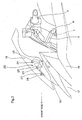
- Fig. 1 is a left side view of a motorcycle 1 having a windshield attaching structure according to a first embodiment of the present invention. Further, the direction concept used in this embodiment coincides with the direction concept seen from the driver of the motorcycle 1.
- the motorcycle 1 has a front wheel 2 and a rear wheel 3, and the front wheel 2 is rotatably supported in the lower portion of a front fork 4 extended in the substantially up and down direction.
- the front fork 4 is supported by a steering shaft 7 via an upper bracket 5 provided at its upper end and an under bracket (not shown) provided downward of the upper bracket 5.
- the steering shaft 7 is rotatably supported by a head pipe 8.
- a bar type steering wheel 9 extended to right and left is attached to the upper bracket 5. Therefore, the driver swings the steering wheel 9 to right and left, so that the front wheel 2 is steered with the steering shaft 7 as a rotational shaft.
- a vehicle body frame 10 is extended rearward from the head pipe 8.
- a front end 11a of a swing arm 11 is axially supported at the rear lower end of the vehicle body frame 10.
- the rear wheel 3 is rotatably supported at the rear end of the swing arm 11.
- a fuel tank 12 is arranged upward of the vehicle body frame 10 and rearward of the steering wheel 9.
- a driver's seat 13 is arranged rearward of the fuel tank 12.
- An engine 14 is mounted substantially immediately below the fuel tank 12.
- a gear case 16 is arranged in the rear portion of a crankcase 15 of the engine 14, so that the power of the gear is transmitted to the rear wheel 3 via a chain (not shown).
- a head lamp 17 is arranged forward of the steering wheel 9, and is covered by a front cowl 18.
- the front cowl 18 is of a full cowl type in which its upper portion covers the head lamp 17 and its lower portion covers the engine 14 and the crankcase 15.
- Fig. 2 is an enlarged view of the upper portion in the front portion of the motorcycle 1 of Fig. 1 .
- Fig. 3 is a diagram of the motorcycle 1 seen from the driver.
- a meter body 51 having a display panel which displays the vehicle speed of the motorcycle 1 is arranged in the upper portion of the front cowl 18, and a meter cover 50 covers the upper portion in the front portion of the meter body 51.
- the meter cover 50 configures part of the upper surface of the front cowl 18.
- a windshield 19 which reduces wind pressure to the driver is arranged in the upper portion of the front cowl 18 and the meter cover 50.
- the windshield 19 is curved so as to have a convex shape forward, and is formed of a transparent resin plate to secure the forward visibility of the driver.
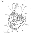
- Fig. 4 is a perspective view of the meter cover 50 portion from which the windshield 19 is removed.
- the meter cover 50 is formed so as to be separated into a rear cover 501 and a front cover 502 coupled to the rear cover 501 and arranged forward of the rear cover 501.
- a pair of right and left throughholes 501a extended in the front and rear direction and formed so that the rear ends thereof reach the rear end of the rear cover 501 are formed in the rear cover 501.
- a pair of right and left throughholes 502a extended in the front and rear direction and formed so that the rear ends thereof reach the rear end of the front cover 502 are formed in the front cover 502.
- the upper portions of shield stays 20 are inserted forward from the rear ends of the rear cover 501 and the front cover 502, so that the upper portions of the shield stays 20 can be attached so as to pass through the rear cover 501 and the front cover 502 upward.
- the length in the right and left direction of the throughholes 501a and 502a can be reduced.
- Fig. 5 is an enlarged left side view of the windshield 19 portion from which the front cowl 18, the meter cover 50, the meter body 51 and the like are removed.
- Fig. 6 is a rear perspective view of the windshield attaching structure from which the windshield 19 is detached.
- the windshield 19 is attached to a pair of right and left shield stays 20.
- the pair of right and left shield stays 20 are coupled by a coupling member 60 extended in the right and left direction.
- the coupling member 60 couples the outermost portions in the right and left direction of the shield stays 20.
- the shield stays 20 are attached to right and left rotation support shafts 30 located at the ends of a center stay 101.
- the center stay 101 is bolted and fixed onto the head pipe 8 formed at the front end of the vehicle body frame 10.
- a lock unit 40 is provided downward and rearward of the shield stays 20, so that the shield stays 20 can be locked in a plurality of angle shift positions.
- the rotation support shafts 30 have axes extended in the horizontal direction and support the shield stays 20 so that the shield stays 20 can be angle-shifted about the axes. Therefore, in the state that the lock unit 40 is unlocked, the shield stays 20 and the windshield 19 can be angle-shifted about the axes of the rotation support shafts 30.
- An upper pipe 102 extended in the right and left direction is attached to the center stay 101.
- Mirror brackets 103 for attaching rear-view mirrors are attached to the right and left ends of the upper pipe 102.
- a meter stay 104 to which the meter body 51 is attached is welded and fixed to the center portion in the right and left direction of the upper pipe 102.
- the lock unit 40 is located downward of the meter stay 104.
- the meter cover 50 which covers the meter body 51 attached to the meter stay 104 covers the rotation support shafts 30 and the upper portion and the front portion of the lock unit 40.
- Later-described shield attaching portions 23 are projected upward from the upper surface of the meter cover 50.
- the windshield 19 is attached to the shield attaching portions 23.
- the shield stays 20 have engaging portions 21, supporting portions 22, and the shield attaching portions 23, respectively.
- the lock unit 40 locks the shield stays 20 at a predetermined angle.
- the supporting portions 22 are supported so as to be angle-shifted by the rotation support shafts 30 about the axes of the rotation support shafts 30.
- the shield stays 20 can be angle-shifted about the rotation support shafts 30 with respect to the center stay 101, that is, the vehicle body frame 10.
- the engaging portions 21 are portions engaged by the abutment of part of the lock unit 40.
- the lock unit 40 is abutted onto the engaging portions 21, so that the shield stays 20 are brought into a locked state in which the angle shift about the axes of the rotation support shafts 30 is inhibited.
- the abutment of the lock unit 40 onto the engaging portions 21 is released, so that the shield stays 20 are brought into an unlocked state in which the angle shift is allowed.
- part of the lock unit 40 is changed between the state that part of the lock unit 40 is abutted onto the engaging portions 21 and the state that part of the lock unit 40 is not abutted onto the engaging portions 21, so that the shield stays 20 can be changed between the locked state in which the shield stays 20 are locked at the predetermined angle and the unlocked state.
- Screws 24 can be attached to the shield attaching portions 23.
- the windshield 19 and the shield attaching portions 23 are fastened by the screws 24 from the front surface side of the windshield 19, so that the windshield 19 is attached to the shield stays 20.
- a plurality of pairs of right and left shield attaching portions 23 are provided according to the pair of right and left shield stays 20, and are provided so as to be spaced from each other in the front and rear direction.
- Fig. 6 three pairs of shield attaching portions 23 are provided.
- Fig. 7 is a front view of the windshield attaching structure of Fig. 6 .
- Fig. 8 is a rear view of the windshield attaching structure of Fig. 6 .
- the supporting portions 22 are arranged near a pair of forwardmost shield attaching portions 23a.
- An interval L1 in the right and left direction of the pair of forwardmost shield attaching portions 23a is shorter than an interval L2 in the right and left direction of the pair of middle shield attaching portions 23 and an interval L3 in the right and left direction of the pair of rear shield attaching portions 23.
- the engaging portions 21 are provided rearward of the supporting portions 22 and downward of the supporting portions 22.
- the supporting portions 22 are arranged toward the shield attaching portions 23 from the engaging portions 21.
- the supporting portions 22 are arranged toward the forwardmost shield attaching portions 23a.
- the supporting portions 22 are formed so as to be extended inward in the right and left direction and rearward and downward from the forwardmost shield attaching portions 23a, and branching portions 26 are formed so as to be extended rearward and outward in the right and left direction from the supporting portions 22 and branched in the up and down direction.
- the engaging portions 21 are provided in the position in which the engaging portions 21 are extended downward from the branching portions 26, and the remaining shield attaching portions 23 are provided in the position in which the remaining shield attaching portions 23 are extended upward from the branching portions 26.
- the shield stays 20 may be configured by joining a plurality of element members.
- first element members having the forwardmost shield attaching portions 23a and the supporting portions 22 and second element members having the engaging portions 21 and the remaining shield attaching portions 23 may be welded so as to be configured as the shield stays 20 as a whole. Further, the second element members may be configured by fastening the engaging portions 21 and the remaining shield attaching portions 23.
- an interval L4 in the right and left direction of the pair of engaging portions 21 is formed so as to be larger than an interval L5 in the right and left direction of the pair of supporting portions 22.
- the pair of engaging portions 21 are arranged in the outermost side portions of the right and left shield stays 20 with respect to the right and left direction.
- the pair of supporting portions 22 are arranged in the innermost side portions of the right and left shield stays 20 with respect to the right and left direction.
- the coupling member 60 which is extended in the right and left direction and couples the pair of engaging portions 21 is provided, so that the strength of the engaging portions 21 can be improved.
- the engaging portions 21 have a pair of right and left plural teeth 211 engaged by projecting portions 41 of the lock unit 40.
- the plural teeth 211 are provided so that the shield stays 20 can be fixed in the plurality of angle shift positions.
- the projecting portions 41 of the lock unit 40 are located in a locked position in which the projecting portions 41 are engaged with recess portions 25 between the teeth 211 so as to hold the shield stays 20 in the predetermined angle shift position.
- the projecting portions 41 of the lock unit 40 are moved into an unlocked position rearward of the recess portions 25, the recess portions 25 and the projecting portions 41 are disengaged to enable the angle shift of the shield stays 20.
- the plurality of teeth 211 are formed at the substantially rear ends of the shield stays 20, so that the projecting portions 41 of the lock unit 40 are located rearward of the shield stays 20.
- the plurality of teeth 211 are formed so as to be arranged side by side in the substantially up and down direction. Regardless of the inclination angle of the shield stays 20, the distances in which the projecting portions 41 are moved between the locked position and the unlocked position are substantially constant, so that the operability of the lock unit 40 can be improved.
- four teeth 211 are provided on each of the right and left sides, and the projecting portions 41 of the lock unit 40 are engaged with the recess portions 25 (three on each of the right and left sides) formed by the teeth 211, so that the shield stays 20 can be located in three angle shift positions.
- each of the recess portions 25 engaged by each of the projecting portions 41 of the lock unit 40 is shifted upward or downward by one tooth (for instance, the projecting portion 41 of the lock unit 40 engaged with a recess portion 251 is engaged with a recess portion 252)
- the inclination angle of the windshield 19 is changed by 5 to 10 degrees.
- the alternate long and two short dashes line of Fig. 5 shows the state that the projecting portion 41 of the lock unit 40 engaged with the recess portion 251 is engaged with a recess portion 253 so that the inclination of the windshield 19 is changed from the minimum inclination angle to the maximum inclination angle.
- the windshield 19 can be angle-shifted by 15 to 30 degrees at a maximum.
- the minimum inclination angle of the windshield 19 is about 30 degrees
- the inclination angle of the windshield 19 is changed by 30 to 60 degrees.
- the lock unit 40 has a body portion 401 extended in the right and left direction along the coupling member 60, ends 402 provided at the right and left ends of the body portion 401 and having the projecting portions 41, and an operating lever 43 extended rearward from the body portion 401.
- Supporting portions 403 supported by the upper pipe 102 are attached to the pair of right and left ends 402, respectively.
- the supporting portions 403 support the ends 402 so as to be rotated about axes parallel with the rotation support shafts 30.
- the ends 402, the lever 43, and the body portion 401 are integrally configured.
- the lever 43 and the projecting portions 41 are provided on the sides opposite each other in the front and rear direction with respect to the supporting portions 403.
- the lock unit 40 is supported by the upper pipe 102.
- a bracket which supports the lock unit 40 is not required to be additionally provided, so that the number of components can be reduced.
- the rotation support shafts 30 are fixed to the center stay 101 which supports the upper pipe 102. Brackets which fix the rotation support shafts 30 are not required to be additionally provided, so that the number of components can be reduced. In this way, the rotation support shafts 30 and the lock unit 40 are supported by the existing components, so that the number of components can be reduced.
- the projecting portions 41 are engaged with the recess portions 25 of the engaging portions 21 of the shield stays 20, and the projecting portions 41 are engaged with the recess portions 25, so that the shield stays 20 are fixed at the predetermined angle.
- an urging unit 42 realized by springs are provided at the ends 402, respectively, and urge the projecting portions 41 in the direction engaging the projecting portions 41 with the recess portions 25 (in the front direction of the vehicle body).
- the lever 43 is extended rearward from the rear ends of the shield stays 20, and passes downward of the upper pipe 102.
- An end 431 of the lever 43 is located rearward of the meter body 51.
- the lock unit 40 has the lever 43 which becomes an operating portion manually operated to change between the locked state and the unlocked state, and the lever 43 is arranged in the position apart from the engaging portions 21 which are engaged with the angle shift of the shield stays 20.
- the lever 43 is arranged in the position in which the lever 43 is exposed from the meter cover 50.
- the lever 43 is arranged downward of the meter cover 50 and the steering wheel 9, so that the lever 43 can be prevented from being noticeable.
- the shield stays 20 are rotatable about the rotation support shafts 30.
- the shield stays 20 are rotated forward about the rotation support shafts 30.
- the inclination angle of the shield stays 20 is increased, and according to that, the inclination angle of the windshield 19 attached to the shield stays 20 is increased.
- the engaging portions 21 are also rotated in an R direction about the rotation support shafts 30.
- the recess portions 25 formed by the teeth 211 provided to the engaging portions 21 are also rotated in the R direction about the rotation support shafts 30.
- the urging unit 42 engage the projecting portions 41 with the recess portions 253 located downward of the recess portions 251. As a result, the shield stays 20 are fixed in the different angle shift position, so that the windshield 19 is fixed in the state that its inclination angle is increased.
- the pair of right and left shield stays 20 are provided, and are coupled by the coupling member 60.
- the pair of right and left shield stays 20 are not required to be provided, and may be, for instance, integrated in the middle portion.
- the shield stays 20 preferably have the plurality of shield attaching portions 23.
- the plurality of pairs of right and left shield attaching portions 23 are preferably provided so as to be spaced from each other in the front and rear direction.
- the engaging portions 21 have the plural teeth 211, and the projecting portions 41 of the lock unit 40 are engaged with the recess portions 25 formed by the teeth 211.
- the inclination angle of the shield stays 20 is changed stepwise.
- the engaging portions 21 and the lock unit 40 may be configured so that the inclination angle of the shield stays 20 is continuously changed.
- the lock unit grips and fixes the rotated engaging portions 21.
- the inclination angle of the shield stays 20 can be continuously changed.
- the recess portions 25 are formed to the engaging portions 21 of the shield stays 20, and the projecting portions 41 are formed to the lock unit 40.
- the projecting portions may be formed to the engaging portions 21 of the shield stays 20, and the recess portions may be formed to the lock unit 40.
- the recess portions are formed to either the shield stays 20 or the lock unit 40, and the convex portions (projecting portions) are formed to the other.
- the shield stay 20 can be changed between the locked state and the unlocked state.
- Fig. 9 is a rear perspective view of the windshield attaching structure according to a second embodiment of the present invention.
- Fig. 10 is a partially rear view of Fig. 9
- Fig. 11 is a partially rear perspective view of Fig. 9 .
- This embodiment and the first embodiment are the same except that the configurations and arrangements of the rotation support shafts, the coupling member, and the lock unit are different. For this reason, in the description of this embodiment, the same components and portions as the first embodiment are indicated by the same reference numerals, and the detailed descriptions of their contents are omitted.
- the pair of right and left shield stays 20 are coupled by a coupling member 71.
- the coupling member 71 is attached to the upper pipe 102.
- a cam portion 711 is provided at one end in the right and left direction (at the right end in this embodiment) of the coupling member 71.
- a rotating member 72 rotated about an axis of the coupling member 71 is arranged rightward and outward of the cam portion 711.
- a cam portion 721 of the rotating member 72 can be engaged with the cam portion 711.
- the rotating member 72 has a gripping portion 722 extended in the radius direction of the coupling member 71.
- the gripping portion 722 is rotated about an axis of the coupling member 71 to change the engaging state of the cam portion 711 and the cam portion 721, so that the distance in the right and left direction between the cam portion 711 and the cam portion 721 can be changed.
- Fig. 9 shows the state that the cam portion 711 and the cam portion 721 are completely engaged with each other and the distance in the right and left direction between the cam portion 711 and the cam portion 721 is minimum.
- Figs. 10 and 11 show the state that the rotating member 72 is rotated, the engagement of the cam portion 711 and the cam portion 721 is released, and the distance in the right and left direction between the cam portion 711 and the cam portion 721 is extended.
- the shield stay 20 is located rightward and outward of the cam portion 721, and a screw 73 fastens the shield stay 20 and the rotating member 72 to the coupling member 71 from the rightward and outward sides of the shield stay 20.
- a long hole 201 is formed in the fastening portion of the shield stay 20 by the screw 73.
- the position of the screw 73 in the long hole 201 is changed, so that the angle shift position of the shield stay 20 can be changed.
- the gripping portion 722 of the rotating member 72 is rotated about an axis of the coupling member 71.
- the cam portion 721 is rotated about an axis of the coupling member 71.
- the cam portion 711 and the cam portion 721 are disengaged, so that the distance in the right and left direction between the cam portion 711 and the cam portion 721 is extended.
- the screw 73 When the distance in the right and left direction between the cam portion 711 and the cam portion 721 is extended, the screw 73 is pressed rightward and outward, the screw 73 can be moved in the long hole 201 of the shield stay 20, and the shield stays 20 can be angle-shifted. Then, the position of the screw 73 in the long hole 201 is changed, so that the shield stays 20 are in the desired angle shift position. Thereafter, the rotating member 72 is rotated in the opposite direction of the first-time rotating direction. As a result, the engaged state of the cam portion 711 and the cam portion 721 is changed (the cam portion 711 and the cam portion 721 are brought into the completely engaged state), so that the distance in the right and left direction between the cam portion 711 and the cam portion 721 is shortened.
- the screw 73 fastens the shield stays 20 to the coupling member 71.
- the shield stays 20 are fixed into the different angle shift portion, so that the windshield 19 is fixed in the state that its inclination angle is changed.
- the inclination angle of the windshield 19 is changed by the shield stays 20, the coupling member 71, the rotating member 72, and the screw 73.
- the simplified windshield attaching structure can be provided.
- the coupling member 71, the rotating member 72, and the screw 73 are covered by the meter cover 50. Appearance can be maintained satisfactory
- the long hole 201 is formed in the fastening portion of the shield stay 20 by the screw 73.
- the screw 73 can be continuously moved in the long hole 201, so that the shield stays 20 can be continuously angle-shifted.
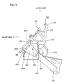
- Fig. 12 is a front perspective view of the windshield attaching structure according to a third embodiment of the present invention
- Fig. 13 is a left side view of Fig. 12 .
- This embodiment and the first embodiment are the same except that the configurations and arrangements of the rotation support shafts, the coupling member, and the lock unit are different. For this reason, in the description of this embodiment, the same components and portions as the first embodiment are indicated by the same reference numerals, and the detailed descriptions of their contents are omitted.
- the pair of right and left shield stays 20 are coupled by a coupling member 81.
- the coupling member 81 is coupled to a first engaging member 83 at a pivot 84 via an arm 82.
- the first engaging member 83 can be rotated with respect to the center stay 101 about a pivot 831.
- the first engaging member 83 can be engaged with a second engaging member 85.
- the second engaging member 85 can be rotated with respect to the center stay 101 about a pivot 851.
- the pair of right and left shield stays 20 are coupled to the center stay 101 by resilient members 86 provided one on each of the right and left sides.
- a pressing member 87 has a lower end which can press down a front end 852 of the second engaging member 85.
- an urging member 853 urges the second engaging member 85 in an X direction to reinforce the engagement of the first engaging member 83 and the second engaging member 85.
- the pressing member 87 is pressed down to rotate the second engaging member 85 in the opposite direction of the X direction about the pivot 851 against the urging force of the urging member 853.
- the second engaging member 85 is rotated in the opposite direction of the X direction, the first engaging member 83 and the second engaging member 85 are disengaged from each other.
- the first engaging member 83 and the second engaging member 85 When the first engaging member 83 and the second engaging member 85 are disengaged from each other, the first engaging member 83 can be rotated about the pivot 831.
- the first engaging member 83 and the shield stays 20 are coupled at a pivot 84 and a pivot 811 via the arm 82, so that the first engaging member 83 is rotated about the pivot 831 to angle-shift the shield stays 20. As a result, the inclination angle of the windshield 19 attached to the shield stays 20 is changed.
- the pressing member 87 When the inclination angle of the windshield 19 is determined, the pressing member 87 is pulled up. The pressing of the second engaging member 85 by the pressing member 87 is released, the second engaging member 85 is rotated in the X direction about the pivot 851 by the urging member 853, and is engaged with the first engaging member 83. Then, the first engaging member 83 is fixed to the center stay 101. As a result, the shield stays 20 are fixed in the different angle shift position, so that the windshield 19 is fixed in the state that its inclination angle is changed.
- the inclination angle of the windshield 19 is changed by the coupling member 81, the arm 82, the first engaging member 83, the second engaging member 85, and the pressing member 87.
- the simplified windshield attaching structure can be provided.
- the coupling member 81, the arm 82, the first engaging member 83, and the second engaging member 85 are covered by the meter cover 50. Appearance can be held satisfactory.
- the first engaging member 83 is rotated about the pivot 831 to angle-shift the shield stays 20.
- the rotation angle of the first engaging member 83 about the pivot 831 can be continuously changed, so that the shield stays 20 can be continuously angle-shifted.
- Fig. 14 is a front perspective view of the windshield attaching structure according to a fourth embodiment of the present invention.
- This embodiment and the first embodiment are the same except that the configurations and arrangements of the coupling member and the lock unit are different. For this reason, in the description of this embodiment, the same components and portions as the first embodiment are indicated by the same reference numerals, and the detailed descriptions of their contents are omitted.
- the pair of right and left shield stays 20 are coupled by the coupling member 60.
- a bolt 91 having a ring-like head is attached to the coupling member 60.
- a screw portion 911 of the bolt 91 is gripped by a gripping member 92 from the right and left sides.
- the gripping member 92 is attached to the center stay 101.
- the position in the up and down direction of the screw portion 911 gripped by the gripping member 92 is changed, so that the bolt 91 is moved up and down with respect to the center stay 101.
- the coupling member 60 gripped by a ring portion 912 of the bolt 91 is moved up and down with respect to the center stay 101.
- the shield stays 20 are angle-shifted with respect to the center stay 101 about the rotation support shafts 30.
- Fig. 15 is a lower perspective view of the gripping member 92 portion of Fig. 14 .
- the gripping member 92 has a gripping portion 921 and a gripping portion 922 which grip the screw portion 911 of the bolt 91 from the right and left sides.
- the gripping portion 921 and the gripping portion 922 are covered by a cover 923.
- Fig. 16 is a diagram showing the gripping member 92 of Fig. 15 from which the cover 923 is detached.
- the gripping portion 921 and the gripping portion 922 are urged by an urging member 927 in the direction gripping the screw portion 911.
- the gripping member 92 has a pulley member 925 which can change the interval of the gap between the gripping portion 921 and the gripping portion 922.
- a wire 924 is wound around the pulley member 925.
- An eccentric member 926 is provided in the position rearward of the pulley member 925 and sandwiched between the gripping portion 921 and the gripping portion 922. The wire 924 is pulled in a Y direction, so that the eccentric member 926 can be rotated about a pivot 925a of the pulley member 925.
- the eccentric member 926 has a substantially elliptical shape having a short axis and a long axis in front view.
- Fig. 17 is a schematic diagram of the gripping member 92 of Fig. 15 in the state that the pulley member 925 is removed, viewed in the direction of an arrow XVII.
- Fig. 18 is a diagram showing the state that the eccentric member 926 of Fig. 17 is rotated about the pivot 925a. As shown in Fig. 17 , in the state that the gripping portion 921 and the gripping portion 922 grip the screw portion 911, the short axis portion of the eccentric member 926 is sandwiched between the gripping portion 921 and the gripping portion 922.
- the wire 924 is pulled in the Y direction, as shown in Fig.
- the eccentric member 926 is rotated about the pivot 925a, so that the longer portion than the short axis portion of the eccentric member 926 is sandwiched between the gripping portion 921 and the gripping portion 922.
- the gap between the gripping portion 921 and the gripping portion 922 is extended against the urging of the urging member 927, so that the gripped state of the screw portion 911 by the gripping portion 921 and the gripping portion 922 is released.
- Fig. 19 is a perspective view of the gripping portion 921. Since the gripping portion 922 has the same configuration as that of the gripping portion 921, the gripping portion 921 will be described as an example.
- the gripping portion 921 has a female screw portion 921a engaged with the screw portion 911 formed with a male screw, and convex portions 921b and hole portions 921c engaged with the gripping portion 922.
- the convex portions 921b and the hole portions 921c are provided one on each of the front and rear sides of the female screw portion 921a, and are staggered with respect to each other in the front and rear direction of the female screw portion 921a.
- the screw portion 911 is formed with a male screw and the female screw portion 921a is formed with a female screw, so that the gripping portion 921 can substantially continuously (at a thread pitch) change the gripping position of the screw portion 911 in the axis direction (that is, in the up and down direction) of the screw portion 911.
- the convex portions 921b of the gripping portion 921 are engaged with the hole portions of the gripping portion 922, and the convex portions of the gripping portion 922 are engaged with the hole portion 921c of the gripping portion 921. In the engagement of the gripping portion 921 and the gripping portion 922, the positioning of the gripping portion 921 and the gripping portion 922 can be easily performed.
- the wire 924 is pulled in the Y direction to rotate the eccentric member 926 about the pivot 925a.
- the gap between the gripping portion 921 and the gripping portion 922 which grip the screw portion 911 of the bolt 91 is increased to release the gripped state of the screw portion 911.
- the bolt 91 When the gripped state of the screw portion 911 is released, the bolt 91 can be moved in the up and down direction to move the bolt 91 in the up and down direction.
- the coupling member 60 By the movement of the bolt 91 in the up and down direction, the coupling member 60 is moved up and down with respect to the center stay 101.
- the shield stays 20 are angle-shifted with respect to the center stay 101 about the rotation support shafts 30, and according to that, the inclination angle of the windshield 19 attached to the shield stays 20 is changed.
- the inclination angle of the windshield 19 is changed by the shield stays 20, the coupling member 60, the bolt 91, and the gripping member 92.
- the simplified windshield attaching structure can be provided.
- the coupling member 60, the bolt 91, and the gripping member 92 are covered by the meter cover 50. Appearance can be held satisfactory.
- the up and down position of the bolt 91 is changed to angle-shift the shield stays 20.
- the gripped position of the bolt 91 by the gripping member 92 can be changed substantially continuously in the up and down direction, so that the shield stays 20 can be continuously angle-shifted.
- the cover member which covers the rotation support shafts 30, the coupling member 60, the lock unit 40 and the like is the meter cover 50.
- the cover member is not limited to the meter cover 50, and may be the cover member arranged in the front portion of the vehicle body, e.g., the front cowl 18. Such cover member is formed into a non-transparent shape, so that the lock unit 40 and the like can be prevented from being noticeable.
- the cover member preferably covers at least the front portion of the lock unit 40 and the like.
- the meter cover 50 arranged rearward of the end of the windshield 19 and forward of the steering wheel 9 covers the lock unit 40 and the like. The present invention is not limited to this.
- Part of the lock unit 40 and the like may be covered by the forward-arranged member other than the meter cover arranged forward of the viewpoint of the driver. Even in a vehicle in which the front cowl 18 and the meter cover 50 are not provided, the meter body 51 may cover, as the forward-arranged member, the lock unit 40 and the like.
- the lock unit 40 and the like is arranged in the region forward of the meter body, preferably, in the region forward and downward thereof, more preferably, in the region on the opposite side of the visibility of the meter body 51 with respect to the visibility direction connecting the viewpoint of the driver and the meter body 51.
- at least part of the lock unit 40 and the like is preferably arranged in the region forward and downward of the steering wheel 9 and the upper bracket 5.
- At least part of the lock unit 40 is covered by the forward-arranged member.
- at least part of the lock unit 40 is covered by the forward-arranged member to simplify the front portion of the vehicle body so that appearance can be improved.
- the lever 43 and the like is used as the operating portion which changes the shield stays 20 between the locked state and the unlocked state.
- a power transmission mechanism which provides power for changing the locked state in the position apart from the engaging portions 21, it may be used as the operating portion.
- the operating portion and the engaging portions 21 are spaced from each other, and using a typical mechanism such as a gear and a belt, power may be transmitted from the operating portion to the engaging portions 21.
- electric power may be used as power for the change between the locked state and the unlocked state, and a switch for providing an electric power instruction may be used as the operating portion.
- an electromagnetic solenoid may be used as the lock unit.
- the present invention has been described using the motorcycle.
- all vehicles having a windshield forward of a driver are applicable.
- the present invention can be suitably used for saddle type vehicles such as small planing boats, buggy vehicles, and all-terrain vehicles.
- the present invention is suitably applicable to vehicles having a windshield forward of the handlebar of a vehicle.
- part of the lock unit and the rotation support shafts are arranged forward and downward of the handlebar. Part of the lock unit and the rotation support shafts are hidden from the visibility of the driver, so that appearance can be improved.
- the windshield attaching structure which can change the inclination angle of the windshield to simplify the front portion of the vehicle body so that appearance can be improved can be provided, the industrial utilization value is high.
Landscapes
- Engineering & Computer Science (AREA)
- Mechanical Engineering (AREA)
- Body Structure For Vehicles (AREA)
- Instrument Panels (AREA)
Claims (7)
- Frontscheibenbefestigungsstruktur für eine Frontscheibe (19), die im oberen Abschnitt des vorderen Abschnitts der Fahrzeugkarosserie eines Fahrzeuges vorgesehen ist und den Winddruck auf einen Fahrer reduziert, wobei die Frontscheibenbefestigungsstruktur aufweist:ein Paar rechter und linker Scheibenständer (20, 20), an welchen eine Frontscheibe (19) befestigbar ist,einen Rotationsabstützschaft (30), der das Paar der rechten und linken Scheibenständer (20, 20) abstützt, um zu einem Rahmen (10) des Fahrzeuges winkelversetzt zu sein; undeine Verriegelungseinheit (40), die das Paar der rechten und linken Scheibenständer (20, 20) zwischen einem verriegelten Zustand, in dem das Paar aus dem rechten und linken Scheibenständer (20, 20) in einer Vielzahl an Winkelversatzpositionen verriegelt ist, und einem entriegelten Zustand, in dem das Paar aus dem rechten und linken Scheibenständer (20, 20) in keiner der Winkelversatzpositionen verriegelt ist, verändern kann,wobei jeder der Scheibenständer (20, 20) einen Eingriffsabschnitt (21), einen Abstützabschnitt (22) und zumindest einen Scheibenbefestigungsabschnitt (23) aufweist, undwobei zumindest ein Abschnitt der Verriegelungseinheit (40) durch ein vorne angeordnetes Element (50), das in dem vorderen Abschnitt des Fahrzeuges angeordnet ist, bedeckt ist,wobei die Verriegelungseinheit (40) einen Betriebsabschnitt (43) aufweist, der manuell betätigt wird, um die Scheibenständer (20, 20) zwischen dem verriegelten Zustand und dem entriegelten Zustand zu verändern,wobei der Betriebsabschnitt (43) an einer Position entfernt von den Eingriffsabschnitten (21, 21) des Paars aus dem rechten und linken Scheibenständer (20, 20), das mit der Verriegelungseinheit (40) in Eingriff steht, angeordnet ist, um von dem vorne angeordneten Element (50) exponiert zu sein,wobei die Abstützabschnitte (22, 22) von jedem Scheibenständer (20, 20) von der Rotationsabstützhülle (30) abgestützt werden und die Scheibenbefestigungsabschnitte an einer Frontscheibe (19) befestigbar sind,wobei die Abstützabschnitte (22, 22) von jedem Scheibenständer (20, 20) in Richtung der Scheibenbefestigungsabschnitte (23, 23) der Eingriffsabschnitte (21, 21) angeordnet sind,dadurch gekennzeichnet, dass der Abstand (L4) in der Richtung von rechts nach links zwischen den rechten und linken Eingriffsabschnitten (21, 21) eingestellt ist, um größer zu sein als der Abstand (L5) in der Richtung von rechts nach links zwischen den rechten und linken Abstützabschnitten (22, 22).
- Frontscheibenbefestigungsstruktur nach Anspruch 1, bei der die Verriegelungseinheit (40) den Eingriffsabschnitt (21) von jedem Scheibenständer hinter dem Verriegelungsabschnitt (22) verriegelt.
- Frontscheibenbefestigungsstruktur nach Anspruch 1 oder 2, bei der die Verriegelungseinheit (40) den Eingriffsabschnitt (21) von jedem Scheibenständer unterhalb des Abstützabschnitts (22) verriegelt.
- Frontscheibenbefestigungsstruktur nach einem der Ansprüche 1 bis 3, bei der der vordere Abschnitt der Verriegelungseinheit (40) und die Rotationsabschnittswelle (30) von dem vorne angeordneten Element bedeckt sind.
- Frontscheibenbefestigungsstruktur nach einem der Ansprüche 1 bis 3, bei der jeder Scheibenständer (20) eine Vielzahl an Scheibenbefestigungsabschnitten (23) aufweist, die vorgesehen sind, um voneinander in der Richtung von vorne nach hinten beabstandet zu sein, und
wobei der Abstützabschnitt (22) von jedem Scheibenständer in der Nähe des vordersten Scheibenbefestigungsabschnitts (23) angeordnet ist. - Frontscheibenbefestigungsstruktur nach einem der Ansprüche 1 bis 3 und 5,
bei der der Eingriffsabschnitt (21) von jedem Scheibenständer eine Vielzahl an Zähnen (211) zur Winkelversatzpositionierung aufweist,
wobei die Verriegelungseinheit (40) einen vorstehenden Abschnitt (41) aufweist, der zwischen einer verriegelten Position und einer entriegelten Position versetzt werden kann,
wobei der vorstehende Abschnitt (41) in die verriegelte Position versetzt wird, um in Eingriff mit einem der Ausnehmungsabschnitte (25) zu stehen, die durch die Zähne des Eingriffsabschnitts ausgebildet werden, sodass die Verriegelungseinheit (40) den Scheibenständer (20) in der vorgegebenen Winkelversatzposition verriegelt, und
wobei der vorstehende Abschnitt (41) in die entriegelte Position versetzt wird, um den vorstehenden Abschnitt (41) und den Eingriffsabschnitt (21) auseinander auszurücken, sodass die Verriegelungseinheit (40) den Scheibenständer (20) entriegelt. - Frontscheibenbefestigungsstruktur nach Anspruch 6, bei der die Verriegelungseinheit (40) eine Drängeinheit (42), die den vorstehenden Abschnitt (41) in der Richtung des Einrückens des Eingriffsabschnitts (21) von jedem Scheibenständer drängt, und einen Betätigungshebel, der das Drängen gegen die Drängeinheit (42) löst, aufweist.
Applications Claiming Priority (1)
| Application Number | Priority Date | Filing Date | Title |
|---|---|---|---|
| JP2010090668A JP5495909B2 (ja) | 2010-04-09 | 2010-04-09 | 乗物のウインドシールド取付構造 |
Publications (2)
| Publication Number | Publication Date |
|---|---|
| EP2374700A1 EP2374700A1 (de) | 2011-10-12 |
| EP2374700B1 true EP2374700B1 (de) | 2013-03-27 |
Family
ID=43984157
Family Applications (1)
| Application Number | Title | Priority Date | Filing Date |
|---|---|---|---|
| EP11161467A Active EP2374700B1 (de) | 2010-04-09 | 2011-04-07 | Windschutzscheibenbefestigungsstruktur für ein Fahrzeug |
Country Status (2)
| Country | Link |
|---|---|
| EP (1) | EP2374700B1 (de) |
| JP (1) | JP5495909B2 (de) |
Families Citing this family (12)
| Publication number | Priority date | Publication date | Assignee | Title |
|---|---|---|---|---|
| JP5492717B2 (ja) * | 2010-09-16 | 2014-05-14 | 川崎重工業株式会社 | 自動二輪車のウィンドスクリーン |
| CN102649453A (zh) * | 2012-05-29 | 2012-08-29 | 力帆实业(集团)股份有限公司 | 车头罩安装支架 |
| CN102897036B (zh) * | 2012-10-12 | 2016-08-03 | 力帆实业(集团)股份有限公司 | 摩托车仪表安装支架 |
| JP5864483B2 (ja) * | 2013-07-10 | 2016-02-17 | 本田技研工業株式会社 | 鞍乗り型車両の前部構造 |
| US10272966B2 (en) | 2014-07-15 | 2019-04-30 | Piaggio & C. S.P.A. | Windscreen safety assembly |
| JP6360751B2 (ja) * | 2014-08-26 | 2018-07-18 | 川崎重工業株式会社 | ウインドシールドの支持構造 |
| JP6001615B2 (ja) * | 2014-09-30 | 2016-10-05 | 本田技研工業株式会社 | 鞍乗り型車両 |
| JP6300743B2 (ja) * | 2015-02-27 | 2018-03-28 | 本田技研工業株式会社 | 鞍乗り型車両におけるスクリーン可動装置 |
| JP6277526B2 (ja) * | 2015-03-30 | 2018-02-14 | 本田技研工業株式会社 | 鞍乗り型車両の走行風取り入れ構造 |
| JP2019051836A (ja) * | 2017-09-15 | 2019-04-04 | 川崎重工業株式会社 | ウインドシールド取付構造 |
| TWI675772B (zh) * | 2019-01-07 | 2019-11-01 | 光陽工業股份有限公司 | 機車擋風鏡構造 |
| JP7681398B2 (ja) | 2020-12-03 | 2025-05-22 | カワサキモータース株式会社 | ウィンドシールドの取付構造 |
Family Cites Families (12)
| Publication number | Priority date | Publication date | Assignee | Title |
|---|---|---|---|---|
| DE3609595A1 (de) * | 1986-03-21 | 1987-09-24 | Wulf Gerstenmaier | Windschutzschild fuer das vorderteil eines motorrades |
| JPS63201889U (de) * | 1987-06-19 | 1988-12-26 | ||
| JPH0534477Y2 (de) * | 1987-10-19 | 1993-08-31 | ||
| JPH0365483A (ja) * | 1989-07-31 | 1991-03-20 | Honda Motor Co Ltd | 自動二輪車のウインドスクリーン |
| DE4418954A1 (de) * | 1994-05-31 | 1995-12-07 | Bayerische Motoren Werke Ag | Einrichtung zum Verstellen eines Windschildes für Fahrzeuge |
| JP4198286B2 (ja) * | 1999-10-13 | 2008-12-17 | 本田技研工業株式会社 | バーハンドル型車両の風防装置 |
| JP2002087355A (ja) * | 2000-09-12 | 2002-03-27 | Yamaha Motor Co Ltd | 自動二輪車の風防装置 |
| JP4341840B2 (ja) * | 2004-12-27 | 2009-10-14 | 本田技研工業株式会社 | 自動二輪車の車体前部構造 |
| JP5149112B2 (ja) * | 2008-02-05 | 2013-02-20 | 本田技研工業株式会社 | 自動二輪車のスクリーン |
| JP2009226961A (ja) * | 2008-03-19 | 2009-10-08 | Honda Motor Co Ltd | 自動二輪車のスクリーン支持構造 |
| JP2010070108A (ja) * | 2008-09-19 | 2010-04-02 | Honda Motor Co Ltd | ウインドスクリーン取付構造 |
| JP2011020616A (ja) * | 2009-07-17 | 2011-02-03 | Suzuki Motor Corp | ウィンドスクリーン装置 |
-
2010
- 2010-04-09 JP JP2010090668A patent/JP5495909B2/ja active Active
-
2011
- 2011-04-07 EP EP11161467A patent/EP2374700B1/de active Active
Also Published As
| Publication number | Publication date |
|---|---|
| JP2011218978A (ja) | 2011-11-04 |
| JP5495909B2 (ja) | 2014-05-21 |
| EP2374700A1 (de) | 2011-10-12 |
Similar Documents
| Publication | Publication Date | Title |
|---|---|---|
| EP2374700B1 (de) | Windschutzscheibenbefestigungsstruktur für ein Fahrzeug | |
| EP3219595B1 (de) | Windschutzscheibenvorrichtung für sattelfahrzeug | |
| US7448663B2 (en) | Guard structure for vehicle seat lock | |
| EP2128007B1 (de) | Motorrad | |
| EP2868557B1 (de) | Motorrad | |
| US20120024102A1 (en) | Articulation device for the steering column of a cycle | |
| EP3950474B1 (de) | Sattelfahrzeug | |
| JP2016159717A (ja) | 鞍乗り型車両におけるスクリーン可動装置 | |
| US8230758B1 (en) | Multiple axis adjustable handlebars and handlebar mounting risers | |
| US11279428B2 (en) | Saddle riding vehicle | |
| US12024255B2 (en) | Straddle type vehicle | |
| JP2009214623A (ja) | 鞍乗型車両 | |
| JP6070327B2 (ja) | スクリーン可変構造 | |
| US11840300B2 (en) | Vehicle body cover and saddle-type vehicle | |
| US7291787B2 (en) | Bicycle electrical wire cover apparatus | |
| EP1772363B1 (de) | Motorroller | |
| JP5095448B2 (ja) | 自動二輪車のスクリーン支持構造 | |
| JP2007118870A (ja) | ヘッドライト支持構造体 | |
| CN110356496B (zh) | 鞍乘型车辆的仪表周边结构 | |
| US7150338B2 (en) | Cover supporting structure for light vehicle | |
| JP7357024B2 (ja) | 鞍乗り型車両の風防装置 | |
| JP7814555B2 (ja) | 鞍乗り型車両のメータ構造 | |
| US20140084643A1 (en) | Grip portion structure for fellow passenger of motorcycle | |
| JP2016078502A (ja) | 鞍乗型車両 | |
| JP7728323B2 (ja) | ナックルガード取付構造およびナックルガード取付ブラケット |
Legal Events
| Date | Code | Title | Description |
|---|---|---|---|
| PUAI | Public reference made under article 153(3) epc to a published international application that has entered the european phase |
Free format text: ORIGINAL CODE: 0009012 |
|
| AK | Designated contracting states |
Kind code of ref document: A1 Designated state(s): AL AT BE BG CH CY CZ DE DK EE ES FI FR GB GR HR HU IE IS IT LI LT LU LV MC MK MT NL NO PL PT RO RS SE SI SK SM TR |
|
| AX | Request for extension of the european patent |
Extension state: BA ME |
|
| 17P | Request for examination filed |
Effective date: 20120328 |
|
| 17Q | First examination report despatched |
Effective date: 20120515 |
|
| GRAP | Despatch of communication of intention to grant a patent |
Free format text: ORIGINAL CODE: EPIDOSNIGR1 |
|
| GRAS | Grant fee paid |
Free format text: ORIGINAL CODE: EPIDOSNIGR3 |
|
| GRAA | (expected) grant |
Free format text: ORIGINAL CODE: 0009210 |
|
| AK | Designated contracting states |
Kind code of ref document: B1 Designated state(s): AL AT BE BG CH CY CZ DE DK EE ES FI FR GB GR HR HU IE IS IT LI LT LU LV MC MK MT NL NO PL PT RO RS SE SI SK SM TR |
|
| REG | Reference to a national code |
Ref country code: GB Ref legal event code: FG4D |
|
| REG | Reference to a national code |
Ref country code: CH Ref legal event code: EP |
|
| REG | Reference to a national code |
Ref country code: AT Ref legal event code: REF Ref document number: 603202 Country of ref document: AT Kind code of ref document: T Effective date: 20130415 |
|
| REG | Reference to a national code |
Ref country code: IE Ref legal event code: FG4D |
|
| REG | Reference to a national code |
Ref country code: DE Ref legal event code: R096 Ref document number: 602011001141 Country of ref document: DE Effective date: 20130523 |
|
| PG25 | Lapsed in a contracting state [announced via postgrant information from national office to epo] |
Ref country code: BG Free format text: LAPSE BECAUSE OF FAILURE TO SUBMIT A TRANSLATION OF THE DESCRIPTION OR TO PAY THE FEE WITHIN THE PRESCRIBED TIME-LIMIT Effective date: 20130627 Ref country code: SE Free format text: LAPSE BECAUSE OF FAILURE TO SUBMIT A TRANSLATION OF THE DESCRIPTION OR TO PAY THE FEE WITHIN THE PRESCRIBED TIME-LIMIT Effective date: 20130327 Ref country code: NO Free format text: LAPSE BECAUSE OF FAILURE TO SUBMIT A TRANSLATION OF THE DESCRIPTION OR TO PAY THE FEE WITHIN THE PRESCRIBED TIME-LIMIT Effective date: 20130627 Ref country code: LT Free format text: LAPSE BECAUSE OF FAILURE TO SUBMIT A TRANSLATION OF THE DESCRIPTION OR TO PAY THE FEE WITHIN THE PRESCRIBED TIME-LIMIT Effective date: 20130327 |
|
| REG | Reference to a national code |
Ref country code: AT Ref legal event code: MK05 Ref document number: 603202 Country of ref document: AT Kind code of ref document: T Effective date: 20130327 |
|
| REG | Reference to a national code |
Ref country code: LT Ref legal event code: MG4D |
|
| PG25 | Lapsed in a contracting state [announced via postgrant information from national office to epo] |
Ref country code: SI Free format text: LAPSE BECAUSE OF FAILURE TO SUBMIT A TRANSLATION OF THE DESCRIPTION OR TO PAY THE FEE WITHIN THE PRESCRIBED TIME-LIMIT Effective date: 20130327 Ref country code: LV Free format text: LAPSE BECAUSE OF FAILURE TO SUBMIT A TRANSLATION OF THE DESCRIPTION OR TO PAY THE FEE WITHIN THE PRESCRIBED TIME-LIMIT Effective date: 20130327 Ref country code: GR Free format text: LAPSE BECAUSE OF FAILURE TO SUBMIT A TRANSLATION OF THE DESCRIPTION OR TO PAY THE FEE WITHIN THE PRESCRIBED TIME-LIMIT Effective date: 20130628 Ref country code: FI Free format text: LAPSE BECAUSE OF FAILURE TO SUBMIT A TRANSLATION OF THE DESCRIPTION OR TO PAY THE FEE WITHIN THE PRESCRIBED TIME-LIMIT Effective date: 20130327 |
|
| REG | Reference to a national code |
Ref country code: NL Ref legal event code: VDEP Effective date: 20130327 |
|
| PG25 | Lapsed in a contracting state [announced via postgrant information from national office to epo] |
Ref country code: BE Free format text: LAPSE BECAUSE OF FAILURE TO SUBMIT A TRANSLATION OF THE DESCRIPTION OR TO PAY THE FEE WITHIN THE PRESCRIBED TIME-LIMIT Effective date: 20130327 Ref country code: HR Free format text: LAPSE BECAUSE OF FAILURE TO SUBMIT A TRANSLATION OF THE DESCRIPTION OR TO PAY THE FEE WITHIN THE PRESCRIBED TIME-LIMIT Effective date: 20130327 |
|
| PG25 | Lapsed in a contracting state [announced via postgrant information from national office to epo] |
Ref country code: IS Free format text: LAPSE BECAUSE OF FAILURE TO SUBMIT A TRANSLATION OF THE DESCRIPTION OR TO PAY THE FEE WITHIN THE PRESCRIBED TIME-LIMIT Effective date: 20130727 Ref country code: PT Free format text: LAPSE BECAUSE OF FAILURE TO SUBMIT A TRANSLATION OF THE DESCRIPTION OR TO PAY THE FEE WITHIN THE PRESCRIBED TIME-LIMIT Effective date: 20130729 Ref country code: EE Free format text: LAPSE BECAUSE OF FAILURE TO SUBMIT A TRANSLATION OF THE DESCRIPTION OR TO PAY THE FEE WITHIN THE PRESCRIBED TIME-LIMIT Effective date: 20130327 Ref country code: AT Free format text: LAPSE BECAUSE OF FAILURE TO SUBMIT A TRANSLATION OF THE DESCRIPTION OR TO PAY THE FEE WITHIN THE PRESCRIBED TIME-LIMIT Effective date: 20130327 Ref country code: RO Free format text: LAPSE BECAUSE OF FAILURE TO SUBMIT A TRANSLATION OF THE DESCRIPTION OR TO PAY THE FEE WITHIN THE PRESCRIBED TIME-LIMIT Effective date: 20130327 Ref country code: NL Free format text: LAPSE BECAUSE OF FAILURE TO SUBMIT A TRANSLATION OF THE DESCRIPTION OR TO PAY THE FEE WITHIN THE PRESCRIBED TIME-LIMIT Effective date: 20130327 Ref country code: SK Free format text: LAPSE BECAUSE OF FAILURE TO SUBMIT A TRANSLATION OF THE DESCRIPTION OR TO PAY THE FEE WITHIN THE PRESCRIBED TIME-LIMIT Effective date: 20130327 Ref country code: ES Free format text: LAPSE BECAUSE OF FAILURE TO SUBMIT A TRANSLATION OF THE DESCRIPTION OR TO PAY THE FEE WITHIN THE PRESCRIBED TIME-LIMIT Effective date: 20130708 Ref country code: CZ Free format text: LAPSE BECAUSE OF FAILURE TO SUBMIT A TRANSLATION OF THE DESCRIPTION OR TO PAY THE FEE WITHIN THE PRESCRIBED TIME-LIMIT Effective date: 20130327 |
|
| PG25 | Lapsed in a contracting state [announced via postgrant information from national office to epo] |
Ref country code: CY Free format text: LAPSE BECAUSE OF FAILURE TO SUBMIT A TRANSLATION OF THE DESCRIPTION OR TO PAY THE FEE WITHIN THE PRESCRIBED TIME-LIMIT Effective date: 20130327 Ref country code: PL Free format text: LAPSE BECAUSE OF FAILURE TO SUBMIT A TRANSLATION OF THE DESCRIPTION OR TO PAY THE FEE WITHIN THE PRESCRIBED TIME-LIMIT Effective date: 20130327 |
|
| PG25 | Lapsed in a contracting state [announced via postgrant information from national office to epo] |
Ref country code: MC Free format text: LAPSE BECAUSE OF FAILURE TO SUBMIT A TRANSLATION OF THE DESCRIPTION OR TO PAY THE FEE WITHIN THE PRESCRIBED TIME-LIMIT Effective date: 20130327 |
|
| REG | Reference to a national code |
Ref country code: IE Ref legal event code: MM4A |
|
| PG25 | Lapsed in a contracting state [announced via postgrant information from national office to epo] |
Ref country code: DK Free format text: LAPSE BECAUSE OF FAILURE TO SUBMIT A TRANSLATION OF THE DESCRIPTION OR TO PAY THE FEE WITHIN THE PRESCRIBED TIME-LIMIT Effective date: 20130327 |
|
| PLBE | No opposition filed within time limit |
Free format text: ORIGINAL CODE: 0009261 |
|
| STAA | Information on the status of an ep patent application or granted ep patent |
Free format text: STATUS: NO OPPOSITION FILED WITHIN TIME LIMIT |
|
| PG25 | Lapsed in a contracting state [announced via postgrant information from national office to epo] |
Ref country code: IT Free format text: LAPSE BECAUSE OF FAILURE TO SUBMIT A TRANSLATION OF THE DESCRIPTION OR TO PAY THE FEE WITHIN THE PRESCRIBED TIME-LIMIT Effective date: 20130327 |
|
| 26N | No opposition filed |
Effective date: 20140103 |
|
| REG | Reference to a national code |
Ref country code: DE Ref legal event code: R097 Ref document number: 602011001141 Country of ref document: DE Effective date: 20140103 |
|
| PG25 | Lapsed in a contracting state [announced via postgrant information from national office to epo] |
Ref country code: IE Free format text: LAPSE BECAUSE OF NON-PAYMENT OF DUE FEES Effective date: 20130407 |
|
| REG | Reference to a national code |
Ref country code: CH Ref legal event code: PL |
|
| PG25 | Lapsed in a contracting state [announced via postgrant information from national office to epo] |
Ref country code: CH Free format text: LAPSE BECAUSE OF NON-PAYMENT OF DUE FEES Effective date: 20140430 Ref country code: LI Free format text: LAPSE BECAUSE OF NON-PAYMENT OF DUE FEES Effective date: 20140430 |
|
| PG25 | Lapsed in a contracting state [announced via postgrant information from national office to epo] |
Ref country code: MT Free format text: LAPSE BECAUSE OF FAILURE TO SUBMIT A TRANSLATION OF THE DESCRIPTION OR TO PAY THE FEE WITHIN THE PRESCRIBED TIME-LIMIT Effective date: 20130327 |
|
| PG25 | Lapsed in a contracting state [announced via postgrant information from national office to epo] |
Ref country code: SM Free format text: LAPSE BECAUSE OF FAILURE TO SUBMIT A TRANSLATION OF THE DESCRIPTION OR TO PAY THE FEE WITHIN THE PRESCRIBED TIME-LIMIT Effective date: 20130327 |
|
| PG25 | Lapsed in a contracting state [announced via postgrant information from national office to epo] |
Ref country code: TR Free format text: LAPSE BECAUSE OF FAILURE TO SUBMIT A TRANSLATION OF THE DESCRIPTION OR TO PAY THE FEE WITHIN THE PRESCRIBED TIME-LIMIT Effective date: 20130327 |
|
| PG25 | Lapsed in a contracting state [announced via postgrant information from national office to epo] |
Ref country code: RS Free format text: LAPSE BECAUSE OF FAILURE TO SUBMIT A TRANSLATION OF THE DESCRIPTION OR TO PAY THE FEE WITHIN THE PRESCRIBED TIME-LIMIT Effective date: 20130627 Ref country code: HU Free format text: LAPSE BECAUSE OF FAILURE TO SUBMIT A TRANSLATION OF THE DESCRIPTION OR TO PAY THE FEE WITHIN THE PRESCRIBED TIME-LIMIT; INVALID AB INITIO Effective date: 20110407 Ref country code: LU Free format text: LAPSE BECAUSE OF NON-PAYMENT OF DUE FEES Effective date: 20130407 Ref country code: MK Free format text: LAPSE BECAUSE OF FAILURE TO SUBMIT A TRANSLATION OF THE DESCRIPTION OR TO PAY THE FEE WITHIN THE PRESCRIBED TIME-LIMIT Effective date: 20130327 |
|
| GBPC | Gb: european patent ceased through non-payment of renewal fee |
Effective date: 20150407 |
|
| PG25 | Lapsed in a contracting state [announced via postgrant information from national office to epo] |
Ref country code: GB Free format text: LAPSE BECAUSE OF NON-PAYMENT OF DUE FEES Effective date: 20150407 |
|
| REG | Reference to a national code |
Ref country code: FR Ref legal event code: PLFP Year of fee payment: 6 |
|
| PGFP | Annual fee paid to national office [announced via postgrant information from national office to epo] |
Ref country code: FR Payment date: 20160309 Year of fee payment: 6 |
|
| REG | Reference to a national code |
Ref country code: FR Ref legal event code: ST Effective date: 20171229 |
|
| PG25 | Lapsed in a contracting state [announced via postgrant information from national office to epo] |
Ref country code: FR Free format text: LAPSE BECAUSE OF NON-PAYMENT OF DUE FEES Effective date: 20170502 |
|
| PG25 | Lapsed in a contracting state [announced via postgrant information from national office to epo] |
Ref country code: AL Free format text: LAPSE BECAUSE OF FAILURE TO SUBMIT A TRANSLATION OF THE DESCRIPTION OR TO PAY THE FEE WITHIN THE PRESCRIBED TIME-LIMIT Effective date: 20130327 |
|
| REG | Reference to a national code |
Ref country code: DE Ref legal event code: R081 Ref document number: 602011001141 Country of ref document: DE Owner name: KAWASAKI MOTORS, LTD., AKASHI-SHI, JP Free format text: FORMER OWNER: KAWASAKI JUKOGYO KABUSHIKI KAISHA, KOBE-SHI, HYOGO, JP |
|
| PGFP | Annual fee paid to national office [announced via postgrant information from national office to epo] |
Ref country code: DE Payment date: 20250305 Year of fee payment: 15 |