EP2373828B1 - Vorrichtung zur oberflächenbehandlung und/oder -beschichtung von substratkomponenten - Google Patents
Vorrichtung zur oberflächenbehandlung und/oder -beschichtung von substratkomponenten Download PDFInfo
- Publication number
- EP2373828B1 EP2373828B1 EP09807664.9A EP09807664A EP2373828B1 EP 2373828 B1 EP2373828 B1 EP 2373828B1 EP 09807664 A EP09807664 A EP 09807664A EP 2373828 B1 EP2373828 B1 EP 2373828B1
- Authority
- EP
- European Patent Office
- Prior art keywords
- coating
- treatment
- substrate
- deposition
- units
- Prior art date
- Legal status (The legal status is an assumption and is not a legal conclusion. Google has not performed a legal analysis and makes no representation as to the accuracy of the status listed.)
- Active
Links
- 238000000576 coating method Methods 0.000 title claims description 113
- 239000011248 coating agent Substances 0.000 title claims description 109
- 239000000758 substrate Substances 0.000 title claims description 99
- 238000011282 treatment Methods 0.000 claims description 90
- 238000000034 method Methods 0.000 claims description 53
- 238000005240 physical vapour deposition Methods 0.000 claims description 29
- 239000000969 carrier Substances 0.000 claims description 26
- 238000000151 deposition Methods 0.000 claims description 24
- 230000008021 deposition Effects 0.000 claims description 24
- 238000004381 surface treatment Methods 0.000 claims description 14
- 238000005530 etching Methods 0.000 claims description 13
- 238000010438 heat treatment Methods 0.000 claims description 12
- 238000009434 installation Methods 0.000 claims description 9
- 230000033001 locomotion Effects 0.000 claims description 9
- 238000010276 construction Methods 0.000 claims description 5
- 238000005192 partition Methods 0.000 claims description 4
- 125000004122 cyclic group Chemical group 0.000 claims 2
- 238000005289 physical deposition Methods 0.000 claims 2
- 239000006200 vaporizer Substances 0.000 claims 2
- 230000008569 process Effects 0.000 description 29
- 239000010410 layer Substances 0.000 description 17
- 239000007789 gas Substances 0.000 description 6
- 239000000463 material Substances 0.000 description 5
- 238000004544 sputter deposition Methods 0.000 description 4
- 238000001816 cooling Methods 0.000 description 3
- 238000005553 drilling Methods 0.000 description 3
- 230000000694 effects Effects 0.000 description 3
- 230000008901 benefit Effects 0.000 description 2
- 238000005229 chemical vapour deposition Methods 0.000 description 2
- 238000013461 design Methods 0.000 description 2
- 238000001704 evaporation Methods 0.000 description 2
- 230000008020 evaporation Effects 0.000 description 2
- 238000007733 ion plating Methods 0.000 description 2
- 238000004519 manufacturing process Methods 0.000 description 2
- 239000002245 particle Substances 0.000 description 2
- 239000010936 titanium Substances 0.000 description 2
- 229910010038 TiAl Inorganic materials 0.000 description 1
- RTAQQCXQSZGOHL-UHFFFAOYSA-N Titanium Chemical compound [Ti] RTAQQCXQSZGOHL-UHFFFAOYSA-N 0.000 description 1
- NRTOMJZYCJJWKI-UHFFFAOYSA-N Titanium nitride Chemical compound [Ti]#N NRTOMJZYCJJWKI-UHFFFAOYSA-N 0.000 description 1
- UQZIWOQVLUASCR-UHFFFAOYSA-N alumane;titanium Chemical compound [AlH3].[Ti] UQZIWOQVLUASCR-UHFFFAOYSA-N 0.000 description 1
- 238000000429 assembly Methods 0.000 description 1
- 230000000712 assembly Effects 0.000 description 1
- 239000012298 atmosphere Substances 0.000 description 1
- 230000004888 barrier function Effects 0.000 description 1
- 230000005540 biological transmission Effects 0.000 description 1
- 230000015572 biosynthetic process Effects 0.000 description 1
- 238000000541 cathodic arc deposition Methods 0.000 description 1
- 239000000919 ceramic Substances 0.000 description 1
- 238000005260 corrosion Methods 0.000 description 1
- 230000007797 corrosion Effects 0.000 description 1
- 238000005520 cutting process Methods 0.000 description 1
- 230000001419 dependent effect Effects 0.000 description 1
- 238000011161 development Methods 0.000 description 1
- 238000011982 device technology Methods 0.000 description 1
- 238000010894 electron beam technology Methods 0.000 description 1
- 238000005516 engineering process Methods 0.000 description 1
- 239000010408 film Substances 0.000 description 1
- 238000010849 ion bombardment Methods 0.000 description 1
- 238000001755 magnetron sputter deposition Methods 0.000 description 1
- 229910052751 metal Inorganic materials 0.000 description 1
- 239000002184 metal Substances 0.000 description 1
- 150000002739 metals Chemical class 0.000 description 1
- 238000003801 milling Methods 0.000 description 1
- 238000012986 modification Methods 0.000 description 1
- 230000004048 modification Effects 0.000 description 1
- 239000002052 molecular layer Substances 0.000 description 1
- 239000012299 nitrogen atmosphere Substances 0.000 description 1
- 230000000704 physical effect Effects 0.000 description 1
- 238000004886 process control Methods 0.000 description 1
- 238000012545 processing Methods 0.000 description 1
- 238000005086 pumping Methods 0.000 description 1
- 230000009467 reduction Effects 0.000 description 1
- 238000000926 separation method Methods 0.000 description 1
- 239000002356 single layer Substances 0.000 description 1
- 238000001228 spectrum Methods 0.000 description 1
- 238000000992 sputter etching Methods 0.000 description 1
- 239000013077 target material Substances 0.000 description 1
- 239000010409 thin film Substances 0.000 description 1
- 229910052719 titanium Inorganic materials 0.000 description 1
- 238000007738 vacuum evaporation Methods 0.000 description 1
- 238000009489 vacuum treatment Methods 0.000 description 1
- 238000007740 vapor deposition Methods 0.000 description 1
- 239000011364 vaporized material Substances 0.000 description 1
- 239000002347 wear-protection layer Substances 0.000 description 1
Images

Classifications
-
- C—CHEMISTRY; METALLURGY
- C23—COATING METALLIC MATERIAL; COATING MATERIAL WITH METALLIC MATERIAL; CHEMICAL SURFACE TREATMENT; DIFFUSION TREATMENT OF METALLIC MATERIAL; COATING BY VACUUM EVAPORATION, BY SPUTTERING, BY ION IMPLANTATION OR BY CHEMICAL VAPOUR DEPOSITION, IN GENERAL; INHIBITING CORROSION OF METALLIC MATERIAL OR INCRUSTATION IN GENERAL
- C23C—COATING METALLIC MATERIAL; COATING MATERIAL WITH METALLIC MATERIAL; SURFACE TREATMENT OF METALLIC MATERIAL BY DIFFUSION INTO THE SURFACE, BY CHEMICAL CONVERSION OR SUBSTITUTION; COATING BY VACUUM EVAPORATION, BY SPUTTERING, BY ION IMPLANTATION OR BY CHEMICAL VAPOUR DEPOSITION, IN GENERAL
- C23C14/00—Coating by vacuum evaporation, by sputtering or by ion implantation of the coating forming material
- C23C14/22—Coating by vacuum evaporation, by sputtering or by ion implantation of the coating forming material characterised by the process of coating
- C23C14/56—Apparatus specially adapted for continuous coating; Arrangements for maintaining the vacuum, e.g. vacuum locks
- C23C14/564—Means for minimising impurities in the coating chamber such as dust, moisture, residual gases
-
- C—CHEMISTRY; METALLURGY
- C23—COATING METALLIC MATERIAL; COATING MATERIAL WITH METALLIC MATERIAL; CHEMICAL SURFACE TREATMENT; DIFFUSION TREATMENT OF METALLIC MATERIAL; COATING BY VACUUM EVAPORATION, BY SPUTTERING, BY ION IMPLANTATION OR BY CHEMICAL VAPOUR DEPOSITION, IN GENERAL; INHIBITING CORROSION OF METALLIC MATERIAL OR INCRUSTATION IN GENERAL
- C23C—COATING METALLIC MATERIAL; COATING MATERIAL WITH METALLIC MATERIAL; SURFACE TREATMENT OF METALLIC MATERIAL BY DIFFUSION INTO THE SURFACE, BY CHEMICAL CONVERSION OR SUBSTITUTION; COATING BY VACUUM EVAPORATION, BY SPUTTERING, BY ION IMPLANTATION OR BY CHEMICAL VAPOUR DEPOSITION, IN GENERAL
- C23C14/00—Coating by vacuum evaporation, by sputtering or by ion implantation of the coating forming material
- C23C14/22—Coating by vacuum evaporation, by sputtering or by ion implantation of the coating forming material characterised by the process of coating
- C23C14/34—Sputtering
- C23C14/35—Sputtering by application of a magnetic field, e.g. magnetron sputtering
-
- C—CHEMISTRY; METALLURGY
- C23—COATING METALLIC MATERIAL; COATING MATERIAL WITH METALLIC MATERIAL; CHEMICAL SURFACE TREATMENT; DIFFUSION TREATMENT OF METALLIC MATERIAL; COATING BY VACUUM EVAPORATION, BY SPUTTERING, BY ION IMPLANTATION OR BY CHEMICAL VAPOUR DEPOSITION, IN GENERAL; INHIBITING CORROSION OF METALLIC MATERIAL OR INCRUSTATION IN GENERAL
- C23C—COATING METALLIC MATERIAL; COATING MATERIAL WITH METALLIC MATERIAL; SURFACE TREATMENT OF METALLIC MATERIAL BY DIFFUSION INTO THE SURFACE, BY CHEMICAL CONVERSION OR SUBSTITUTION; COATING BY VACUUM EVAPORATION, BY SPUTTERING, BY ION IMPLANTATION OR BY CHEMICAL VAPOUR DEPOSITION, IN GENERAL
- C23C14/00—Coating by vacuum evaporation, by sputtering or by ion implantation of the coating forming material
- C23C14/22—Coating by vacuum evaporation, by sputtering or by ion implantation of the coating forming material characterised by the process of coating
- C23C14/56—Apparatus specially adapted for continuous coating; Arrangements for maintaining the vacuum, e.g. vacuum locks
-
- C—CHEMISTRY; METALLURGY
- C23—COATING METALLIC MATERIAL; COATING MATERIAL WITH METALLIC MATERIAL; CHEMICAL SURFACE TREATMENT; DIFFUSION TREATMENT OF METALLIC MATERIAL; COATING BY VACUUM EVAPORATION, BY SPUTTERING, BY ION IMPLANTATION OR BY CHEMICAL VAPOUR DEPOSITION, IN GENERAL; INHIBITING CORROSION OF METALLIC MATERIAL OR INCRUSTATION IN GENERAL
- C23C—COATING METALLIC MATERIAL; COATING MATERIAL WITH METALLIC MATERIAL; SURFACE TREATMENT OF METALLIC MATERIAL BY DIFFUSION INTO THE SURFACE, BY CHEMICAL CONVERSION OR SUBSTITUTION; COATING BY VACUUM EVAPORATION, BY SPUTTERING, BY ION IMPLANTATION OR BY CHEMICAL VAPOUR DEPOSITION, IN GENERAL
- C23C16/00—Chemical coating by decomposition of gaseous compounds, without leaving reaction products of surface material in the coating, i.e. chemical vapour deposition [CVD] processes
- C23C16/44—Chemical coating by decomposition of gaseous compounds, without leaving reaction products of surface material in the coating, i.e. chemical vapour deposition [CVD] processes characterised by the method of coating
- C23C16/54—Apparatus specially adapted for continuous coating
Definitions
- the invention relates to a device and a method for surface treatment and / or coating of substrate components by deposition from the gas phase, in particular by physical vapor deposition after the PVD (Physical Vapor Deposition) or the reactive PVD method, according to the preamble of Patent claim 1 or claim 14.
- PVD Physical Vapor Deposition
- the reactive PVD method according to the preamble of Patent claim 1 or claim 14.
- workpiece surfaces ie on substrate components very thin layers, such as corrosion or wear protection layers such.
- Such thin films often find in tool production, especially in the production of precision cutting tools, such. As drilling, milling or reaming tools application.
- the coating material is first by applying a suitable physical effects, such. B. by an electron beam, an arc (Arc-PVD) or sputtered by sputtering.
- a suitable physical effects such. B. by an electron beam, an arc (Arc-PVD) or sputtered by sputtering.
- the vaporized material then impinges on the substrate surface, where it comes to film formation.
- the vapor particles In order for the vapor particles to reach the substrate, it is necessary to work with negative pressure. In this process, there is a linear particle movement, so that the substrate must be moved so that the entire substrate surface can be uniformly and homogeneously coated.
- PVD process In order to convert the coating materials, such as metals in the gas phase, various ways are taken by the PVD process, such as sputtering, including magnetron sputtering, ion plating, including reactive ion plating, or the laser evaporation or the vacuum evaporation. All methods have in common that in order to achieve the desired coating or treatment effect, the process parameters such as gas atmosphere, temperature and orientation of the substrate surface to the coating material must be met very accurately. Therefore, conventional coating systems have been constructed so that the treatment chamber room for several substrate carriers and coating and / or treatment units such. As evaporator sources, cathodes, targets, magnetrons, etc., offers. Such vacuum treatment plants are z. B. in the DE 10 2005 050 358 A1 or in the DE 10 2006 020 004 A1 described.
- the substrates to be coated or treated can be provided with only a single layer type. Even if this type of layer is a multi-layer, as for example in the document US 6,051,113
- the document GB 2 303 380 A discloses a sputtering apparatus for the surface treatment and / or coating of substrate components according to the PVD method with a deposition or treatment chamber in which a plurality of substrates and a plurality of coating or treatment units are arranged.
- the device may have a modular design. By changing the treatment time, the power of the magnetron or the BIAS voltage, it is possible to subject the substrates of a batch to a different treatment.
- the flexibility of the use of this known device remains limited because in the separated chamber sections from each other independently or simultaneously no different treatments of the substrates can be made.
- the invention is therefore an apparatus for surface treatment and / or coating of substrate components by deposition from the gas phase, in particular by physical vapor deposition by the PVD method, and a method for operating such a device to provide, with or with the it succeeds in minimizing the process and delivery times.
- the device is constructed so that it can be equipped with modules, in such a way that in a batch in the
- Coating device introduced substrate components after closing the coating / treatment space of a different treatment, i. a coating or a surface treatment can be subjected.
- the inventive design of the device to increase the utilization rate of the coating system considerably and also to operate the coating system much more economical and with greatly improved energy efficiency. Because the inventively larger number of substrate components in the coating system is only once to heat and cool, thereby process time is saved to a considerable extent.
- the method according to the invention is characterized in that coating and / or treatment units and shielding modules are assembled according to a desired coating and / or treatment program for substrate components to be coated differently, and then the substrate carriers are loaded with those substrate components which are in a batch should be subjected to the same treatment. After closing the treatment chamber, the shielding modules and the process control of the system then ensure that the substrate components combined on the individual substrate carriers are subjected to an individual coating and / or treatment program. In this case, according to a further development of the method, a different treatment of the substrate components at different locations of the coating chamber can take place simultaneously.
- the available installation space of the treatment chamber is advantageously utilized, with the additional advantage that the different treatments of the substrate components can take place simultaneously due to the spatial separation of the treatment stations.
- This opens up the possibility of subjecting different substrate carriers before selected coating and / or treatment units to individual treatment with precisely controlled process parameters without being influenced by adjacent coating and / or treatment units. This makes it possible to achieve a very accurate and homogeneous growth rate of the layer.
- the shielding device according to claim 2 which is preferably in turn formed as a module, it is possible to save valuable tree space, because by means of the shielding module substrate components can be subjected to different treatment even in the smallest space.
- the partitions may be made of different materials, including ceramic and / or perforated sheet material.
- a kinematics is provided, with which the relative position between the substrate carriers and the coating and / or treatment units and / or heaters can be changed in a closed deposition or treatment chamber.
- the rotary drive device for the assembly table is simultaneously used as an indexing device for positioning selected substrate carriers with respect to selected coating and / or treatment units, as a result of which the complexity of the control technology becomes smaller.
- a rotary drive for example in the form of a shaft, provided for a substrate carrier at each mounting location of the assembly table. It is possible in this way, the coating system at 100% filling with even To operate to be coated substrate elements in a conventional manner, without losing the flexibility of the system described above.
- a selected substrate carrier in the immediate vicinity of a coating and / or treatment unit are set in rotary motion, without operating the clock mode, whereby it succeeds on these selected substrate components to deposit an extremely homogeneous and precisely defined in its thickness layer.
- the coating system according to the invention also makes it possible to operate selected coating and / or treatment units synchronously, thereby saving further processing time.
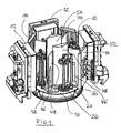
- the figures schematically show the components accommodated in the interior of a process chamber of a coating installation (not shown) which are required for coating substrate components according to the PVD method or according to the reactive PVD method.
- the assemblies shown in the figures are arranged in an evacuable and preferably provided with different gas connections coating chamber or vacuum chamber.
- Such vacuum chambers are known, so that can be dispensed with a detailed description of this chamber here.
- the peculiarity of the coating system to be described in detail below is how the interior of the evacuatable deposition or treatment chamber can be equipped to significantly increase the efficiency in the operation of such a system and to minimize the process times of the system due to improved flexibility.
- coating and / or treatment modules 12 are arranged at predetermined angular intervals. These coating and / or treatment modules 12 are formed, for example, by evaporators or so-called sputtering cathodes with modularly populated targets, wherein in addition - so-called shutters - not shown in detail - could be used. Such coating or treatment modules are known per se, so that a more detailed description of these components is unnecessary here. It should be emphasized, however, that the present invention is not limited to specific treatment / coating modules. Rather, all units regularly used in the coating process according to the PVD method can be used. In addition to the coating / treatment modules 12 heating units 14 are additionally provided, which are usually arranged between the treatment modules 12 and can also be designed as modules.
- etching anode denoted by 16 which interacts with a central filament cathode not shown in detail above which lie above the coating modules 12 and heating units 14 in the region of the dome of the coating chamber (not shown).
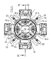
- Fig. 1 shows the arrangement of the modules required for the coating or treatment with the deposition or treatment chamber open, while in the plan view according to Fig. 2 the arrangement is shown with the chamber closed. It follows from this illustration that part of the coating modules 12 and heating units 14 grouped around the assembly table 10 can be mounted on a separate component which serves as a loading door for the vacuum chamber. The remaining coating and heating modules are mounted on a support structure which - just like the loading door - has mounting points for the flexible arrangement of the coating and heating modules.
- the mounting table 10 is designed as a kind of carousel and he wears - as best of the Fig. 2 It can be seen - a plurality of, that is, in the illustrated embodiment 8, preferably identically designed mounting positions 18-1 to 18-8, which can be equipped individually with different modules.
- Each mounting place 18-1 to 18-8 is associated with a drive shaft 22, each having a vertical axis of rotation.
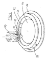
- the drive shaft 22 is rotatably coupled to a vertical support shaft 24, the turntable 26 in predetermined and preferably adjustable axial distances with plug-in receptacles 30 for supporting substrate components, such as eg boring tools.
- the plug-in receptacles are designed so that the drilling tools project with the surface sections to be coated or treated from the plug receptacle.
- the support shaft 24 is stabilized.
- the plug-in receptacles and thus also the substrate components when turning the turntable 26 perform a same or counter-rotating rotation about the also vertical axis of the plug-receptacle.
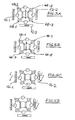
- FIG. 4 is schematically based on one of the representation of FIGS. 1 to 3 slightly modified kinematics indicated how the rotational movement of the mounting table 10 and the drive shafts 22 can be transmitted.
- a drive gear 32 which is in mesh with the internal teeth of a first ring gear 34.
- the ring gear 34 is rotatably connected to an axially offset, larger diameter second ring gear 36 which can be driven via its internal teeth by means of a first drive pinion 38.
- the drive gear 32 supporting shaft 22 extends rotatably supported by the mounting table 10 therethrough and is rotatably mounted in a likewise below the mounting table 10 lying gear 40 which is driven via a second drive pinion 42.
- the gear 40 takes the drive shafts 22 and thus the mounting table 10 in the direction of rotation with. In this way, the mounting table 10 can be clocked.
- the drive gears 32 roll on the internal teeth of the first ring gear 34.
- the rotational speed of the first ring gear 34 can be kept as large as the rotational speed of the gear 40, so that during the clock movement of the mounting table 10, a rotation of the drive shafts 22 is omitted.
- the assembly sites 18-1, 18-3, 18-5, and 18-7 are different from the assembly sites 18-2, 18-4, 18-6, and 18-8. They carry a cover plate 44 which has a holder 46 for a radially aligned shielding plate 48 above the covered drive shaft 22. Between the two adjacent shielding plates 48 of the assembly stations 18-1 and 18-7 or 18-3 and 18-5, a further, stationarily mounted Ablewandan whatsoever 50 is provided, each of which is formed by a convex sheet 52 and a secant sheet 54 and the shields the space between the adjacent radial shield plates 48 to the adjacent mounting locations. Also, the shielding plates 48 and the Ablewandanowskiowski extract 50 are designed as modules and they can - depending on the arrangement of the other treatment / coating components are mounted at different locations in the interior of the coating chamber.
- a drive device with which the relative position between the substrate carriers 26 and the coating and / or treatment units 12 is variable with closed deposition or treatment chamber, there is the possibility of the coating system even if only a few substrate components be provided with a specific coating or subjected to a specific treatment to operate economically.
- the coating and / or treatment units 12 such as evaporator, cathodes, targets, magnetrons, filament cathode and etching anode and the shielding 48, 50 of modules in the deposition or treatment chamber according to a desired coating or treatment program for the Substrate components are assembled and, accordingly, the substrate carrier 26 are equipped with those substrate components to be subjected to the same treatment.
- the deposition or treatment chamber can be closed, after which the individual treatment or coating programs for the substrate components grouped together on the substrate carriers (26) can be run through in one batch.
- a multiple heating and cooling of the substrate components and substrate support can be omitted, whereby process time can be saved to a considerable extent and the utilization of the coating system can be greatly increased even for small batches.
- the process phases of pumping, heating and cooling are the same for all substrate carriers, the assembly table 10 or the carousel rotates about its axis.
- the carousel 10 stops and the substrate carriers 26 at positions 4 and 8 rotate about their own axis.
- the etching phase can begin ( FIG. 5A ).
- Positions 4 and 8 rotate about their own axis, and the right and left vaporizers TiAl and Ti associated with these positions are ignited, and if present, after burnout (if possible), a shutter not shown in detail is opened , Position 4 is - after building a suitable nitrogen atmosphere - coated with titanium nitride and position 8 with titanium aluminum nitride. Depending on the layer thickness achieved, the evaporators are switched off and / or the associated shutter is closed. The drive continues to clock in the position according to FIG. 5D ,
- positions 2 and 6 can be coated with a nano-layer. If positions 2 and 6 reach the evaporator required for the next layer, the corresponding evaporator and / or the shutter, if present, will open. The respective situation can be separated. The position then rotates again about its own axis.
- Each position can be coated individually or simultaneously by different evaporators.
- Abschottmodule instead of the positionable at the assembly stations Abschottmodule also Abschott stylesen can be used, either radially or axially in inserted the interior of the treatment chamber, and or moved and / or erect.
- a kinematic reversal can take place in the region of the drive for the substrate carriers, so that the assembly table remains stationary and the treatment / coating units are driven.
- etching anode instead of the etching anode, it is also possible to use other functional units for the pretreatment of the substrate in the coating chamber, whereby the spatial arrangement of these functional units, for example due to the process, can vary within wide limits.
- the drive kinematics for providing the required relative movements between the substrate components and the coating or treatment units can be freely varied. The only thing that matters is that the drive is able to subject the mounting table, the substrate carrier and advantageously also the holder for the individual substrate components of a relative rotational movement with respect to the treatment units.
- Another possibility of operation is that the coating process is shortened by only selected substrate carriers loaded and thus the system is charged only with a reduced amount and in the treatment only the sector is heated in which a treatment or coating is to be made.
- the invention thus provides a device for surface treatment and / or coating of substrate components by deposition from the gas phase, in particular by physical vapor deposition after the PVD (Physical Vapor Deposition) or reactive PVD process.
- PVD Physical Vapor Deposition
- a plurality of substrate carriers and a plurality of coating and / or treatment units such as evaporator sources, cathodes, targets, magnetrons, filament cathode and etching anode are arranged.
- evaporator sources, cathodes, targets, magnetrons, filament cathode and etching anode are arranged.
- it can be equipped in such a modular manner that the substrate components introduced into the plant in a batch can be subjected to a different treatment (coating, surface treatment).
Landscapes
- Chemical & Material Sciences (AREA)
- Chemical Kinetics & Catalysis (AREA)
- Engineering & Computer Science (AREA)
- Materials Engineering (AREA)
- Mechanical Engineering (AREA)
- Metallurgy (AREA)
- Organic Chemistry (AREA)
- General Chemical & Material Sciences (AREA)
- Physical Vapour Deposition (AREA)
Applications Claiming Priority (2)
| Application Number | Priority Date | Filing Date | Title |
|---|---|---|---|
| DE102008062332A DE102008062332A1 (de) | 2008-12-15 | 2008-12-15 | Vorrichtung zur Oberflächenbehandlung und/oder -beschichtung von Substratkomponenten |
| PCT/DE2009/001712 WO2010069289A1 (de) | 2008-12-15 | 2009-12-04 | Vorrichtung zur oberflächenbehandlung und/oder -beschichtung von substratkomponenten |
Publications (2)
| Publication Number | Publication Date |
|---|---|
| EP2373828A1 EP2373828A1 (de) | 2011-10-12 |
| EP2373828B1 true EP2373828B1 (de) | 2014-11-12 |
Family
ID=41818515
Family Applications (1)
| Application Number | Title | Priority Date | Filing Date |
|---|---|---|---|
| EP09807664.9A Active EP2373828B1 (de) | 2008-12-15 | 2009-12-04 | Vorrichtung zur oberflächenbehandlung und/oder -beschichtung von substratkomponenten |
Country Status (13)
| Country | Link |
|---|---|
| US (2) | US20110305833A1 (enExample) |
| EP (1) | EP2373828B1 (enExample) |
| JP (1) | JP5700454B2 (enExample) |
| KR (1) | KR20110098764A (enExample) |
| CN (1) | CN102245799B (enExample) |
| AU (1) | AU2009328788B2 (enExample) |
| BR (1) | BRPI0923092B1 (enExample) |
| CA (1) | CA2748893A1 (enExample) |
| DE (1) | DE102008062332A1 (enExample) |
| EA (1) | EA023891B1 (enExample) |
| MX (1) | MX2011006238A (enExample) |
| SG (1) | SG172178A1 (enExample) |
| WO (1) | WO2010069289A1 (enExample) |
Families Citing this family (17)
| Publication number | Priority date | Publication date | Assignee | Title |
|---|---|---|---|---|
| DE102010032591A1 (de) | 2010-07-23 | 2012-01-26 | Leybold Optics Gmbh | Vorrichtung und Verfahren zur Vakuumbeschichtung |
| CN102560373B (zh) * | 2010-12-16 | 2014-12-17 | 北京北方微电子基地设备工艺研究中心有限责任公司 | 基片加热腔室、使用基片加热腔室的方法及基片处理设备 |
| CN102560381A (zh) * | 2010-12-29 | 2012-07-11 | 鸿富锦精密工业(深圳)有限公司 | 溅镀装置 |
| EP2664690B1 (en) * | 2012-05-15 | 2015-09-16 | ZhongAo HuiCheng Technology Co. Ltd. | A magnetron sputtering coating device and the preparation method of a nano-multilayer film |
| EP2868768B1 (en) | 2013-10-29 | 2021-06-16 | Oerlikon Surface Solutions AG, Pfäffikon | Shutter system |
| CN103643205B (zh) * | 2013-12-04 | 2015-11-18 | 王普 | 一种真空镀膜机 |
| WO2015161469A1 (zh) * | 2014-04-23 | 2015-10-29 | 中奥汇成科技股份有限公司 | 一种人工关节臼杯、磁控溅射镀膜装置及其制备方法 |
| CN104120389B (zh) * | 2014-08-04 | 2016-08-24 | 上海和辉光电有限公司 | 镀膜设备 |
| JP6823392B2 (ja) * | 2016-07-05 | 2021-02-03 | 東京エレクトロン株式会社 | 絶縁膜を形成する方法 |
| CN107130213B (zh) * | 2017-05-03 | 2019-04-09 | 成都真锐科技涂层技术有限公司 | 多元合金复合薄膜制备设备和制备方法 |
| CN112166208B (zh) * | 2017-07-19 | 2023-12-12 | 因特瓦克公司 | 用于形成纳米层合光学涂层的系统 |
| KR102022927B1 (ko) * | 2017-10-19 | 2019-09-19 | 재단법인 오송첨단의료산업진흥재단 | 의료용 peek 소재 표면의 마이크로 기공 구조의 타이타늄 코팅 방법 |
| CN109023245B (zh) * | 2017-12-08 | 2020-04-03 | 西安穿越光电科技有限公司 | 一种高稳定性oled蒸镀设备 |
| KR20210130762A (ko) * | 2019-02-20 | 2021-11-01 | 외를리콘 서피스 솔루션즈 아게, 페피콘 | 모듈식 코팅 시설에서 기판을 수송 및 이동시키기 위한 최적화된 시스템 및 방법 |
| CN109898062A (zh) * | 2019-03-07 | 2019-06-18 | 厦门阿匹斯智能制造系统有限公司 | 一种磁控溅射镀膜设备及镀膜方法 |
| CN115896747B (zh) * | 2021-09-30 | 2024-10-15 | 馗鼎奈米科技(深圳)有限公司 | 表面处理设备 |
| US12331400B2 (en) | 2022-11-07 | 2025-06-17 | Creating Nano Technologies, Inc. | Surface treatment apparatus |
Family Cites Families (21)
| Publication number | Priority date | Publication date | Assignee | Title |
|---|---|---|---|---|
| US4485759A (en) * | 1983-01-19 | 1984-12-04 | Multi-Arc Vacuum Systems Inc. | Planetary substrate support apparatus for vapor vacuum deposition coating |
| JPS59157281A (ja) * | 1983-02-24 | 1984-09-06 | Tokuda Seisakusho Ltd | スパツタリング装置 |
| US5328583A (en) * | 1991-11-05 | 1994-07-12 | Canon Kabushiki Kaisha | Sputtering apparatus and process for forming lamination film employing the apparatus |
| GB9405442D0 (en) * | 1994-03-19 | 1994-05-04 | Applied Vision Ltd | Apparatus for coating substrates |
| GB9514773D0 (en) * | 1995-07-19 | 1995-09-20 | Teer Coatings Ltd | Methods for improving the sputter deposition of metal-sulphur coatings e.g.molybdenum disulphide(MoS2) coatings |
| US6054029A (en) * | 1996-02-23 | 2000-04-25 | Singulus Technologies Gmbh | Device for gripping, holdings and/or transporting substrates |
| DE29615190U1 (de) * | 1996-03-11 | 1996-11-28 | Balzers Verschleissschutz GmbH, 55411 Bingen | Anlage zur Beschichtung von Werkstücken |
| US6174377B1 (en) * | 1997-03-03 | 2001-01-16 | Genus, Inc. | Processing chamber for atomic layer deposition processes |
| DE19738234C1 (de) * | 1997-09-02 | 1998-10-22 | Fraunhofer Ges Forschung | Einrichtung zum Aufstäuben von Hartstoffschichten |
| US6051113A (en) | 1998-04-27 | 2000-04-18 | Cvc Products, Inc. | Apparatus and method for multi-target physical-vapor deposition of a multi-layer material structure using target indexing |
| US6576062B2 (en) * | 2000-01-06 | 2003-06-10 | Tokyo Electron Limited | Film forming apparatus and film forming method |
| US6630053B2 (en) * | 2000-08-22 | 2003-10-07 | Asm Japan K.K. | Semiconductor processing module and apparatus |
| JP2006051594A (ja) * | 2004-07-14 | 2006-02-23 | Mitsubishi Materials Corp | 耐熱合金の高速重切削で硬質被覆層がすぐれた耐チッピング性を発揮する表面被覆超硬合金製切削工具 |
| CH697552B1 (de) | 2004-11-12 | 2008-11-28 | Oerlikon Trading Ag | Vakuumbehandlungsanlage. |
| US9997338B2 (en) * | 2005-03-24 | 2018-06-12 | Oerlikon Surface Solutions Ag, Pfäffikon | Method for operating a pulsed arc source |
| US20070218702A1 (en) * | 2006-03-15 | 2007-09-20 | Asm Japan K.K. | Semiconductor-processing apparatus with rotating susceptor |
| DE102006020004B4 (de) | 2006-04-26 | 2011-06-01 | Systec System- Und Anlagentechnik Gmbh & Co.Kg | Vorrichtung und Verfahren zur homogenen PVD-Beschichtung |
| WO2008013469A1 (en) * | 2006-07-26 | 2008-01-31 | Dmitry Davidovich Spivakov | Method for ion-plasma application of film coatings and a device for carrying out said method |
| CN100575540C (zh) * | 2006-08-28 | 2009-12-30 | 北京有色金属研究总院 | 批量化制备双面高温超导薄膜装置 |
| JPWO2008050384A1 (ja) * | 2006-10-23 | 2010-02-25 | オーエスジー株式会社 | 硬質積層被膜、硬質積層被膜被覆工具、および被膜形成方法 |
| JP4768699B2 (ja) * | 2006-11-30 | 2011-09-07 | キヤノンアネルバ株式会社 | 電力導入装置及び成膜方法 |
-
2008
- 2008-12-15 DE DE102008062332A patent/DE102008062332A1/de not_active Withdrawn
-
2009
- 2009-12-04 KR KR1020117014943A patent/KR20110098764A/ko not_active Ceased
- 2009-12-04 CN CN200980150003.0A patent/CN102245799B/zh not_active Expired - Fee Related
- 2009-12-04 SG SG2011043791A patent/SG172178A1/en unknown
- 2009-12-04 AU AU2009328788A patent/AU2009328788B2/en not_active Ceased
- 2009-12-04 WO PCT/DE2009/001712 patent/WO2010069289A1/de not_active Ceased
- 2009-12-04 CA CA2748893A patent/CA2748893A1/en not_active Abandoned
- 2009-12-04 EP EP09807664.9A patent/EP2373828B1/de active Active
- 2009-12-04 JP JP2011539893A patent/JP5700454B2/ja active Active
- 2009-12-04 MX MX2011006238A patent/MX2011006238A/es active IP Right Grant
- 2009-12-04 BR BRPI0923092-0A patent/BRPI0923092B1/pt not_active IP Right Cessation
- 2009-12-04 EA EA201170814A patent/EA023891B1/ru not_active IP Right Cessation
-
2011
- 2011-05-10 US US13/104,394 patent/US20110305833A1/en not_active Abandoned
-
2013
- 2013-04-01 US US13/854,311 patent/US10711349B2/en active Active
Also Published As
| Publication number | Publication date |
|---|---|
| AU2009328788A1 (en) | 2011-07-28 |
| MX2011006238A (es) | 2011-06-28 |
| CA2748893A1 (en) | 2010-06-24 |
| US20110305833A1 (en) | 2011-12-15 |
| EA201170814A1 (ru) | 2011-12-30 |
| SG172178A1 (en) | 2011-07-28 |
| JP2012512321A (ja) | 2012-05-31 |
| DE102008062332A1 (de) | 2010-06-17 |
| AU2009328788B2 (en) | 2015-10-29 |
| JP5700454B2 (ja) | 2015-04-15 |
| CN102245799B (zh) | 2014-02-12 |
| KR20110098764A (ko) | 2011-09-01 |
| US20130216711A1 (en) | 2013-08-22 |
| WO2010069289A1 (de) | 2010-06-24 |
| BRPI0923092B1 (pt) | 2020-02-11 |
| EP2373828A1 (de) | 2011-10-12 |
| CN102245799A (zh) | 2011-11-16 |
| BRPI0923092A2 (pt) | 2016-07-26 |
| EA023891B1 (ru) | 2016-07-29 |
| US10711349B2 (en) | 2020-07-14 |
Similar Documents
| Publication | Publication Date | Title |
|---|---|---|
| EP2373828B1 (de) | Vorrichtung zur oberflächenbehandlung und/oder -beschichtung von substratkomponenten | |
| EP1025277B1 (de) | Vakuumbeschichtungsanlage und kopplungsanordnung und herstellungsverfahren für werkstücke | |
| EP0312694B1 (de) | Vorrichtung nach dem Karussell-Prinzip zum Beschichten von Substraten | |
| DE4005956C1 (enExample) | ||
| EP0550003B1 (de) | Vakuumbehandlungsanlage und deren Verwendungen | |
| DE2047749A1 (de) | Zirkuläres System zur kontinuierlichen Verrichtung verschiedener im Vakuum durch zuführender Prozesse | |
| EP0518109B1 (de) | Vakuumbehandlungsanlage | |
| DE3507337A1 (de) | Vorrichtung zur durchfuehrung von prozessen im vakuum | |
| DE19626861B4 (de) | Vakuumbehandlungsanlage zum Aufbringen dünner Schichten auf Substrate, beispielsweise auf Scheinwerferreflektoren | |
| WO2015059228A1 (de) | Multimagnetronanordnung | |
| EP1617456B1 (de) | Antriebsmechanismus für eine Vakuum-Behandlungsanlage | |
| WO2018108426A1 (de) | Anlage, verfahren und träger zur beschichtung von brillengläsern | |
| DE102008046318A1 (de) | Vakuumbedampfungsvorrichtung, Vakuumbedampfungsverfahren und verdampfter Gegenstand | |
| EP0953657A2 (de) | Vakuumbeschichtungsanlage | |
| CH692741A5 (de) | Verfahren zur Herstellung in Vakuum oberflächenbehandelter Werkstücke und Vakuumbehandlungsanlage zu dessen Durchführung | |
| DE19624609B4 (de) | Vakuumbehandlungsanlage zum Aufbringen dünner Schichten auf Substrate, beispielsweise auf Scheinwerferreflektoren | |
| DE102012104475A1 (de) | Carousel-Reactor | |
| DE10323295B4 (de) | Vakuumbeschichtungsanlage und Verfahren zur Beschichtung von Substraten | |
| DE102004028840B4 (de) | Verfahren und Vorrichtung zum Herstellen von Mehrschichtsystemen | |
| DE19639933C1 (de) | Rundtaktofen zum Behandeln von Werkstücken | |
| DD291783B5 (de) | Zerstäubungseinrichtung mit rotierendem Substratträger | |
| EP2598453A1 (de) | Vorrichtung und verfahren zur substratprozessierung | |
| DE2420430A1 (de) | Apparat zum aufdampfen duenner schichten |
Legal Events
| Date | Code | Title | Description |
|---|---|---|---|
| PUAI | Public reference made under article 153(3) epc to a published international application that has entered the european phase |
Free format text: ORIGINAL CODE: 0009012 |
|
| 17P | Request for examination filed |
Effective date: 20110705 |
|
| AK | Designated contracting states |
Kind code of ref document: A1 Designated state(s): AT BE BG CH CY CZ DE DK EE ES FI FR GB GR HR HU IE IS IT LI LT LU LV MC MK MT NL NO PL PT RO SE SI SK SM TR |
|
| DAX | Request for extension of the european patent (deleted) | ||
| 17Q | First examination report despatched |
Effective date: 20130620 |
|
| GRAP | Despatch of communication of intention to grant a patent |
Free format text: ORIGINAL CODE: EPIDOSNIGR1 |
|
| INTG | Intention to grant announced |
Effective date: 20140526 |
|
| GRAS | Grant fee paid |
Free format text: ORIGINAL CODE: EPIDOSNIGR3 |
|
| GRAA | (expected) grant |
Free format text: ORIGINAL CODE: 0009210 |
|
| AK | Designated contracting states |
Kind code of ref document: B1 Designated state(s): AT BE BG CH CY CZ DE DK EE ES FI FR GB GR HR HU IE IS IT LI LT LU LV MC MK MT NL NO PL PT RO SE SI SK SM TR |
|
| REG | Reference to a national code |
Ref country code: GB Ref legal event code: FG4D Free format text: NOT ENGLISH |
|
| REG | Reference to a national code |
Ref country code: CH Ref legal event code: EP |
|
| REG | Reference to a national code |
Ref country code: AT Ref legal event code: REF Ref document number: 695835 Country of ref document: AT Kind code of ref document: T Effective date: 20141115 |
|
| REG | Reference to a national code |
Ref country code: IE Ref legal event code: FG4D Free format text: LANGUAGE OF EP DOCUMENT: GERMAN |
|
| REG | Reference to a national code |
Ref country code: DE Ref legal event code: R096 Ref document number: 502009010224 Country of ref document: DE Effective date: 20141224 |
|
| GBCC | Gb: corrected translation (of claims) filed (gb section 80(3)/1977) | ||
| REG | Reference to a national code |
Ref country code: NL Ref legal event code: VDEP Effective date: 20141112 |
|
| PG25 | Lapsed in a contracting state [announced via postgrant information from national office to epo] |
Ref country code: ES Free format text: LAPSE BECAUSE OF FAILURE TO SUBMIT A TRANSLATION OF THE DESCRIPTION OR TO PAY THE FEE WITHIN THE PRESCRIBED TIME-LIMIT Effective date: 20141112 Ref country code: LT Free format text: LAPSE BECAUSE OF FAILURE TO SUBMIT A TRANSLATION OF THE DESCRIPTION OR TO PAY THE FEE WITHIN THE PRESCRIBED TIME-LIMIT Effective date: 20141112 Ref country code: NO Free format text: LAPSE BECAUSE OF FAILURE TO SUBMIT A TRANSLATION OF THE DESCRIPTION OR TO PAY THE FEE WITHIN THE PRESCRIBED TIME-LIMIT Effective date: 20150212 Ref country code: IS Free format text: LAPSE BECAUSE OF FAILURE TO SUBMIT A TRANSLATION OF THE DESCRIPTION OR TO PAY THE FEE WITHIN THE PRESCRIBED TIME-LIMIT Effective date: 20150312 Ref country code: PT Free format text: LAPSE BECAUSE OF FAILURE TO SUBMIT A TRANSLATION OF THE DESCRIPTION OR TO PAY THE FEE WITHIN THE PRESCRIBED TIME-LIMIT Effective date: 20150312 Ref country code: FI Free format text: LAPSE BECAUSE OF FAILURE TO SUBMIT A TRANSLATION OF THE DESCRIPTION OR TO PAY THE FEE WITHIN THE PRESCRIBED TIME-LIMIT Effective date: 20141112 Ref country code: NL Free format text: LAPSE BECAUSE OF FAILURE TO SUBMIT A TRANSLATION OF THE DESCRIPTION OR TO PAY THE FEE WITHIN THE PRESCRIBED TIME-LIMIT Effective date: 20141112 |
|
| PG25 | Lapsed in a contracting state [announced via postgrant information from national office to epo] |
Ref country code: PL Free format text: LAPSE BECAUSE OF FAILURE TO SUBMIT A TRANSLATION OF THE DESCRIPTION OR TO PAY THE FEE WITHIN THE PRESCRIBED TIME-LIMIT Effective date: 20141112 Ref country code: HR Free format text: LAPSE BECAUSE OF FAILURE TO SUBMIT A TRANSLATION OF THE DESCRIPTION OR TO PAY THE FEE WITHIN THE PRESCRIBED TIME-LIMIT Effective date: 20141112 Ref country code: LV Free format text: LAPSE BECAUSE OF FAILURE TO SUBMIT A TRANSLATION OF THE DESCRIPTION OR TO PAY THE FEE WITHIN THE PRESCRIBED TIME-LIMIT Effective date: 20141112 Ref country code: CY Free format text: LAPSE BECAUSE OF FAILURE TO SUBMIT A TRANSLATION OF THE DESCRIPTION OR TO PAY THE FEE WITHIN THE PRESCRIBED TIME-LIMIT Effective date: 20141112 Ref country code: SE Free format text: LAPSE BECAUSE OF FAILURE TO SUBMIT A TRANSLATION OF THE DESCRIPTION OR TO PAY THE FEE WITHIN THE PRESCRIBED TIME-LIMIT Effective date: 20141112 Ref country code: GR Free format text: LAPSE BECAUSE OF FAILURE TO SUBMIT A TRANSLATION OF THE DESCRIPTION OR TO PAY THE FEE WITHIN THE PRESCRIBED TIME-LIMIT Effective date: 20150213 |
|
| PG25 | Lapsed in a contracting state [announced via postgrant information from national office to epo] |
Ref country code: BE Free format text: LAPSE BECAUSE OF NON-PAYMENT OF DUE FEES Effective date: 20141231 |
|
| PG25 | Lapsed in a contracting state [announced via postgrant information from national office to epo] |
Ref country code: DK Free format text: LAPSE BECAUSE OF FAILURE TO SUBMIT A TRANSLATION OF THE DESCRIPTION OR TO PAY THE FEE WITHIN THE PRESCRIBED TIME-LIMIT Effective date: 20141112 Ref country code: EE Free format text: LAPSE BECAUSE OF FAILURE TO SUBMIT A TRANSLATION OF THE DESCRIPTION OR TO PAY THE FEE WITHIN THE PRESCRIBED TIME-LIMIT Effective date: 20141112 Ref country code: SK Free format text: LAPSE BECAUSE OF FAILURE TO SUBMIT A TRANSLATION OF THE DESCRIPTION OR TO PAY THE FEE WITHIN THE PRESCRIBED TIME-LIMIT Effective date: 20141112 Ref country code: RO Free format text: LAPSE BECAUSE OF FAILURE TO SUBMIT A TRANSLATION OF THE DESCRIPTION OR TO PAY THE FEE WITHIN THE PRESCRIBED TIME-LIMIT Effective date: 20141112 Ref country code: CZ Free format text: LAPSE BECAUSE OF FAILURE TO SUBMIT A TRANSLATION OF THE DESCRIPTION OR TO PAY THE FEE WITHIN THE PRESCRIBED TIME-LIMIT Effective date: 20141112 |
|
| REG | Reference to a national code |
Ref country code: CH Ref legal event code: PL |
|
| REG | Reference to a national code |
Ref country code: DE Ref legal event code: R097 Ref document number: 502009010224 Country of ref document: DE |
|
| PG25 | Lapsed in a contracting state [announced via postgrant information from national office to epo] |
Ref country code: MC Free format text: LAPSE BECAUSE OF FAILURE TO SUBMIT A TRANSLATION OF THE DESCRIPTION OR TO PAY THE FEE WITHIN THE PRESCRIBED TIME-LIMIT Effective date: 20141112 |
|
| PLBE | No opposition filed within time limit |
Free format text: ORIGINAL CODE: 0009261 |
|
| STAA | Information on the status of an ep patent application or granted ep patent |
Free format text: STATUS: NO OPPOSITION FILED WITHIN TIME LIMIT |
|
| REG | Reference to a national code |
Ref country code: IE Ref legal event code: MM4A |
|
| REG | Reference to a national code |
Ref country code: FR Ref legal event code: ST Effective date: 20150831 |
|
| 26N | No opposition filed |
Effective date: 20150813 |
|
| GBPC | Gb: european patent ceased through non-payment of renewal fee |
Effective date: 20150212 |
|
| PG25 | Lapsed in a contracting state [announced via postgrant information from national office to epo] |
Ref country code: IE Free format text: LAPSE BECAUSE OF NON-PAYMENT OF DUE FEES Effective date: 20141204 Ref country code: LI Free format text: LAPSE BECAUSE OF NON-PAYMENT OF DUE FEES Effective date: 20141231 Ref country code: CH Free format text: LAPSE BECAUSE OF NON-PAYMENT OF DUE FEES Effective date: 20141231 |
|
| PG25 | Lapsed in a contracting state [announced via postgrant information from national office to epo] |
Ref country code: FR Free format text: LAPSE BECAUSE OF NON-PAYMENT OF DUE FEES Effective date: 20150112 |
|
| PG25 | Lapsed in a contracting state [announced via postgrant information from national office to epo] |
Ref country code: IT Free format text: LAPSE BECAUSE OF FAILURE TO SUBMIT A TRANSLATION OF THE DESCRIPTION OR TO PAY THE FEE WITHIN THE PRESCRIBED TIME-LIMIT Effective date: 20141112 |
|
| PG25 | Lapsed in a contracting state [announced via postgrant information from national office to epo] |
Ref country code: GB Free format text: LAPSE BECAUSE OF NON-PAYMENT OF DUE FEES Effective date: 20150212 |
|
| REG | Reference to a national code |
Ref country code: AT Ref legal event code: MM01 Ref document number: 695835 Country of ref document: AT Kind code of ref document: T Effective date: 20141204 |
|
| PG25 | Lapsed in a contracting state [announced via postgrant information from national office to epo] |
Ref country code: SI Free format text: LAPSE BECAUSE OF FAILURE TO SUBMIT A TRANSLATION OF THE DESCRIPTION OR TO PAY THE FEE WITHIN THE PRESCRIBED TIME-LIMIT Effective date: 20141112 |
|
| PG25 | Lapsed in a contracting state [announced via postgrant information from national office to epo] |
Ref country code: SM Free format text: LAPSE BECAUSE OF FAILURE TO SUBMIT A TRANSLATION OF THE DESCRIPTION OR TO PAY THE FEE WITHIN THE PRESCRIBED TIME-LIMIT Effective date: 20141112 |
|
| PG25 | Lapsed in a contracting state [announced via postgrant information from national office to epo] |
Ref country code: AT Free format text: LAPSE BECAUSE OF NON-PAYMENT OF DUE FEES Effective date: 20141204 |
|
| PG25 | Lapsed in a contracting state [announced via postgrant information from national office to epo] |
Ref country code: BG Free format text: LAPSE BECAUSE OF FAILURE TO SUBMIT A TRANSLATION OF THE DESCRIPTION OR TO PAY THE FEE WITHIN THE PRESCRIBED TIME-LIMIT Effective date: 20141112 |
|
| PG25 | Lapsed in a contracting state [announced via postgrant information from national office to epo] |
Ref country code: MT Free format text: LAPSE BECAUSE OF FAILURE TO SUBMIT A TRANSLATION OF THE DESCRIPTION OR TO PAY THE FEE WITHIN THE PRESCRIBED TIME-LIMIT Effective date: 20141112 Ref country code: HU Free format text: LAPSE BECAUSE OF FAILURE TO SUBMIT A TRANSLATION OF THE DESCRIPTION OR TO PAY THE FEE WITHIN THE PRESCRIBED TIME-LIMIT; INVALID AB INITIO Effective date: 20091204 Ref country code: TR Free format text: LAPSE BECAUSE OF FAILURE TO SUBMIT A TRANSLATION OF THE DESCRIPTION OR TO PAY THE FEE WITHIN THE PRESCRIBED TIME-LIMIT Effective date: 20141112 Ref country code: LU Free format text: LAPSE BECAUSE OF NON-PAYMENT OF DUE FEES Effective date: 20141204 |
|
| PG25 | Lapsed in a contracting state [announced via postgrant information from national office to epo] |
Ref country code: MK Free format text: LAPSE BECAUSE OF FAILURE TO SUBMIT A TRANSLATION OF THE DESCRIPTION OR TO PAY THE FEE WITHIN THE PRESCRIBED TIME-LIMIT Effective date: 20141112 |
|
| PGFP | Annual fee paid to national office [announced via postgrant information from national office to epo] |
Ref country code: DE Payment date: 20241231 Year of fee payment: 16 |