EP2373828B1 - Apparatus for treating and/or coating the surface of a substrate component - Google Patents
Apparatus for treating and/or coating the surface of a substrate component Download PDFInfo
- Publication number
- EP2373828B1 EP2373828B1 EP09807664.9A EP09807664A EP2373828B1 EP 2373828 B1 EP2373828 B1 EP 2373828B1 EP 09807664 A EP09807664 A EP 09807664A EP 2373828 B1 EP2373828 B1 EP 2373828B1
- Authority
- EP
- European Patent Office
- Prior art keywords
- coating
- treatment
- substrate
- deposition
- units
- Prior art date
- Legal status (The legal status is an assumption and is not a legal conclusion. Google has not performed a legal analysis and makes no representation as to the accuracy of the status listed.)
- Active
Links
- 238000000576 coating method Methods 0.000 title claims description 113
- 239000011248 coating agent Substances 0.000 title claims description 109
- 239000000758 substrate Substances 0.000 title claims description 99
- 238000011282 treatment Methods 0.000 claims description 90
- 238000000034 method Methods 0.000 claims description 53
- 238000005240 physical vapour deposition Methods 0.000 claims description 29
- 239000000969 carrier Substances 0.000 claims description 26
- 238000000151 deposition Methods 0.000 claims description 24
- 230000008021 deposition Effects 0.000 claims description 24
- 238000004381 surface treatment Methods 0.000 claims description 14
- 238000005530 etching Methods 0.000 claims description 13
- 238000010438 heat treatment Methods 0.000 claims description 12
- 238000009434 installation Methods 0.000 claims description 9
- 230000033001 locomotion Effects 0.000 claims description 9
- 238000010276 construction Methods 0.000 claims description 5
- 238000005192 partition Methods 0.000 claims description 4
- 125000004122 cyclic group Chemical group 0.000 claims 2
- 238000005289 physical deposition Methods 0.000 claims 2
- 239000006200 vaporizer Substances 0.000 claims 2
- 230000008569 process Effects 0.000 description 29
- 239000010410 layer Substances 0.000 description 17
- 239000007789 gas Substances 0.000 description 6
- 239000000463 material Substances 0.000 description 5
- 238000004544 sputter deposition Methods 0.000 description 4
- 238000001816 cooling Methods 0.000 description 3
- 238000005553 drilling Methods 0.000 description 3
- 230000000694 effects Effects 0.000 description 3
- 230000008901 benefit Effects 0.000 description 2
- 238000005229 chemical vapour deposition Methods 0.000 description 2
- 238000013461 design Methods 0.000 description 2
- 238000001704 evaporation Methods 0.000 description 2
- 230000008020 evaporation Effects 0.000 description 2
- 238000007733 ion plating Methods 0.000 description 2
- 238000004519 manufacturing process Methods 0.000 description 2
- 239000002245 particle Substances 0.000 description 2
- 239000010936 titanium Substances 0.000 description 2
- 229910010038 TiAl Inorganic materials 0.000 description 1
- RTAQQCXQSZGOHL-UHFFFAOYSA-N Titanium Chemical compound [Ti] RTAQQCXQSZGOHL-UHFFFAOYSA-N 0.000 description 1
- NRTOMJZYCJJWKI-UHFFFAOYSA-N Titanium nitride Chemical compound [Ti]#N NRTOMJZYCJJWKI-UHFFFAOYSA-N 0.000 description 1
- UQZIWOQVLUASCR-UHFFFAOYSA-N alumane;titanium Chemical compound [AlH3].[Ti] UQZIWOQVLUASCR-UHFFFAOYSA-N 0.000 description 1
- 238000000429 assembly Methods 0.000 description 1
- 230000000712 assembly Effects 0.000 description 1
- 239000012298 atmosphere Substances 0.000 description 1
- 230000004888 barrier function Effects 0.000 description 1
- 230000005540 biological transmission Effects 0.000 description 1
- 230000015572 biosynthetic process Effects 0.000 description 1
- 238000000541 cathodic arc deposition Methods 0.000 description 1
- 239000000919 ceramic Substances 0.000 description 1
- 238000005260 corrosion Methods 0.000 description 1
- 230000007797 corrosion Effects 0.000 description 1
- 238000005520 cutting process Methods 0.000 description 1
- 230000001419 dependent effect Effects 0.000 description 1
- 238000011161 development Methods 0.000 description 1
- 238000011982 device technology Methods 0.000 description 1
- 238000010894 electron beam technology Methods 0.000 description 1
- 238000005516 engineering process Methods 0.000 description 1
- 239000010408 film Substances 0.000 description 1
- 238000010849 ion bombardment Methods 0.000 description 1
- 238000001755 magnetron sputter deposition Methods 0.000 description 1
- 229910052751 metal Inorganic materials 0.000 description 1
- 239000002184 metal Substances 0.000 description 1
- 150000002739 metals Chemical class 0.000 description 1
- 238000003801 milling Methods 0.000 description 1
- 238000012986 modification Methods 0.000 description 1
- 230000004048 modification Effects 0.000 description 1
- 239000002052 molecular layer Substances 0.000 description 1
- 239000012299 nitrogen atmosphere Substances 0.000 description 1
- 230000000704 physical effect Effects 0.000 description 1
- 238000004886 process control Methods 0.000 description 1
- 238000012545 processing Methods 0.000 description 1
- 238000005086 pumping Methods 0.000 description 1
- 230000009467 reduction Effects 0.000 description 1
- 238000000926 separation method Methods 0.000 description 1
- 239000002356 single layer Substances 0.000 description 1
- 238000001228 spectrum Methods 0.000 description 1
- 238000000992 sputter etching Methods 0.000 description 1
- 239000013077 target material Substances 0.000 description 1
- 239000010409 thin film Substances 0.000 description 1
- 229910052719 titanium Inorganic materials 0.000 description 1
- 238000007738 vacuum evaporation Methods 0.000 description 1
- 238000009489 vacuum treatment Methods 0.000 description 1
- 238000007740 vapor deposition Methods 0.000 description 1
- 239000011364 vaporized material Substances 0.000 description 1
- 239000002347 wear-protection layer Substances 0.000 description 1
Images

Classifications
-
- C—CHEMISTRY; METALLURGY
- C23—COATING METALLIC MATERIAL; COATING MATERIAL WITH METALLIC MATERIAL; CHEMICAL SURFACE TREATMENT; DIFFUSION TREATMENT OF METALLIC MATERIAL; COATING BY VACUUM EVAPORATION, BY SPUTTERING, BY ION IMPLANTATION OR BY CHEMICAL VAPOUR DEPOSITION, IN GENERAL; INHIBITING CORROSION OF METALLIC MATERIAL OR INCRUSTATION IN GENERAL
- C23C—COATING METALLIC MATERIAL; COATING MATERIAL WITH METALLIC MATERIAL; SURFACE TREATMENT OF METALLIC MATERIAL BY DIFFUSION INTO THE SURFACE, BY CHEMICAL CONVERSION OR SUBSTITUTION; COATING BY VACUUM EVAPORATION, BY SPUTTERING, BY ION IMPLANTATION OR BY CHEMICAL VAPOUR DEPOSITION, IN GENERAL
- C23C14/00—Coating by vacuum evaporation, by sputtering or by ion implantation of the coating forming material
- C23C14/22—Coating by vacuum evaporation, by sputtering or by ion implantation of the coating forming material characterised by the process of coating
- C23C14/56—Apparatus specially adapted for continuous coating; Arrangements for maintaining the vacuum, e.g. vacuum locks
- C23C14/564—Means for minimising impurities in the coating chamber such as dust, moisture, residual gases
-
- C—CHEMISTRY; METALLURGY
- C23—COATING METALLIC MATERIAL; COATING MATERIAL WITH METALLIC MATERIAL; CHEMICAL SURFACE TREATMENT; DIFFUSION TREATMENT OF METALLIC MATERIAL; COATING BY VACUUM EVAPORATION, BY SPUTTERING, BY ION IMPLANTATION OR BY CHEMICAL VAPOUR DEPOSITION, IN GENERAL; INHIBITING CORROSION OF METALLIC MATERIAL OR INCRUSTATION IN GENERAL
- C23C—COATING METALLIC MATERIAL; COATING MATERIAL WITH METALLIC MATERIAL; SURFACE TREATMENT OF METALLIC MATERIAL BY DIFFUSION INTO THE SURFACE, BY CHEMICAL CONVERSION OR SUBSTITUTION; COATING BY VACUUM EVAPORATION, BY SPUTTERING, BY ION IMPLANTATION OR BY CHEMICAL VAPOUR DEPOSITION, IN GENERAL
- C23C14/00—Coating by vacuum evaporation, by sputtering or by ion implantation of the coating forming material
- C23C14/22—Coating by vacuum evaporation, by sputtering or by ion implantation of the coating forming material characterised by the process of coating
- C23C14/34—Sputtering
- C23C14/35—Sputtering by application of a magnetic field, e.g. magnetron sputtering
-
- C—CHEMISTRY; METALLURGY
- C23—COATING METALLIC MATERIAL; COATING MATERIAL WITH METALLIC MATERIAL; CHEMICAL SURFACE TREATMENT; DIFFUSION TREATMENT OF METALLIC MATERIAL; COATING BY VACUUM EVAPORATION, BY SPUTTERING, BY ION IMPLANTATION OR BY CHEMICAL VAPOUR DEPOSITION, IN GENERAL; INHIBITING CORROSION OF METALLIC MATERIAL OR INCRUSTATION IN GENERAL
- C23C—COATING METALLIC MATERIAL; COATING MATERIAL WITH METALLIC MATERIAL; SURFACE TREATMENT OF METALLIC MATERIAL BY DIFFUSION INTO THE SURFACE, BY CHEMICAL CONVERSION OR SUBSTITUTION; COATING BY VACUUM EVAPORATION, BY SPUTTERING, BY ION IMPLANTATION OR BY CHEMICAL VAPOUR DEPOSITION, IN GENERAL
- C23C14/00—Coating by vacuum evaporation, by sputtering or by ion implantation of the coating forming material
- C23C14/22—Coating by vacuum evaporation, by sputtering or by ion implantation of the coating forming material characterised by the process of coating
- C23C14/56—Apparatus specially adapted for continuous coating; Arrangements for maintaining the vacuum, e.g. vacuum locks
-
- C—CHEMISTRY; METALLURGY
- C23—COATING METALLIC MATERIAL; COATING MATERIAL WITH METALLIC MATERIAL; CHEMICAL SURFACE TREATMENT; DIFFUSION TREATMENT OF METALLIC MATERIAL; COATING BY VACUUM EVAPORATION, BY SPUTTERING, BY ION IMPLANTATION OR BY CHEMICAL VAPOUR DEPOSITION, IN GENERAL; INHIBITING CORROSION OF METALLIC MATERIAL OR INCRUSTATION IN GENERAL
- C23C—COATING METALLIC MATERIAL; COATING MATERIAL WITH METALLIC MATERIAL; SURFACE TREATMENT OF METALLIC MATERIAL BY DIFFUSION INTO THE SURFACE, BY CHEMICAL CONVERSION OR SUBSTITUTION; COATING BY VACUUM EVAPORATION, BY SPUTTERING, BY ION IMPLANTATION OR BY CHEMICAL VAPOUR DEPOSITION, IN GENERAL
- C23C16/00—Chemical coating by decomposition of gaseous compounds, without leaving reaction products of surface material in the coating, i.e. chemical vapour deposition [CVD] processes
- C23C16/44—Chemical coating by decomposition of gaseous compounds, without leaving reaction products of surface material in the coating, i.e. chemical vapour deposition [CVD] processes characterised by the method of coating
- C23C16/54—Apparatus specially adapted for continuous coating
Definitions
- the invention relates to a device and a method for surface treatment and / or coating of substrate components by deposition from the gas phase, in particular by physical vapor deposition after the PVD (Physical Vapor Deposition) or the reactive PVD method, according to the preamble of Patent claim 1 or claim 14.
- PVD Physical Vapor Deposition
- the reactive PVD method according to the preamble of Patent claim 1 or claim 14.
- workpiece surfaces ie on substrate components very thin layers, such as corrosion or wear protection layers such.
- Such thin films often find in tool production, especially in the production of precision cutting tools, such. As drilling, milling or reaming tools application.
- the coating material is first by applying a suitable physical effects, such. B. by an electron beam, an arc (Arc-PVD) or sputtered by sputtering.
- a suitable physical effects such. B. by an electron beam, an arc (Arc-PVD) or sputtered by sputtering.
- the vaporized material then impinges on the substrate surface, where it comes to film formation.
- the vapor particles In order for the vapor particles to reach the substrate, it is necessary to work with negative pressure. In this process, there is a linear particle movement, so that the substrate must be moved so that the entire substrate surface can be uniformly and homogeneously coated.
- PVD process In order to convert the coating materials, such as metals in the gas phase, various ways are taken by the PVD process, such as sputtering, including magnetron sputtering, ion plating, including reactive ion plating, or the laser evaporation or the vacuum evaporation. All methods have in common that in order to achieve the desired coating or treatment effect, the process parameters such as gas atmosphere, temperature and orientation of the substrate surface to the coating material must be met very accurately. Therefore, conventional coating systems have been constructed so that the treatment chamber room for several substrate carriers and coating and / or treatment units such. As evaporator sources, cathodes, targets, magnetrons, etc., offers. Such vacuum treatment plants are z. B. in the DE 10 2005 050 358 A1 or in the DE 10 2006 020 004 A1 described.
- the substrates to be coated or treated can be provided with only a single layer type. Even if this type of layer is a multi-layer, as for example in the document US 6,051,113
- the document GB 2 303 380 A discloses a sputtering apparatus for the surface treatment and / or coating of substrate components according to the PVD method with a deposition or treatment chamber in which a plurality of substrates and a plurality of coating or treatment units are arranged.
- the device may have a modular design. By changing the treatment time, the power of the magnetron or the BIAS voltage, it is possible to subject the substrates of a batch to a different treatment.
- the flexibility of the use of this known device remains limited because in the separated chamber sections from each other independently or simultaneously no different treatments of the substrates can be made.
- the invention is therefore an apparatus for surface treatment and / or coating of substrate components by deposition from the gas phase, in particular by physical vapor deposition by the PVD method, and a method for operating such a device to provide, with or with the it succeeds in minimizing the process and delivery times.
- the device is constructed so that it can be equipped with modules, in such a way that in a batch in the
- Coating device introduced substrate components after closing the coating / treatment space of a different treatment, i. a coating or a surface treatment can be subjected.
- the inventive design of the device to increase the utilization rate of the coating system considerably and also to operate the coating system much more economical and with greatly improved energy efficiency. Because the inventively larger number of substrate components in the coating system is only once to heat and cool, thereby process time is saved to a considerable extent.
- the method according to the invention is characterized in that coating and / or treatment units and shielding modules are assembled according to a desired coating and / or treatment program for substrate components to be coated differently, and then the substrate carriers are loaded with those substrate components which are in a batch should be subjected to the same treatment. After closing the treatment chamber, the shielding modules and the process control of the system then ensure that the substrate components combined on the individual substrate carriers are subjected to an individual coating and / or treatment program. In this case, according to a further development of the method, a different treatment of the substrate components at different locations of the coating chamber can take place simultaneously.
- the available installation space of the treatment chamber is advantageously utilized, with the additional advantage that the different treatments of the substrate components can take place simultaneously due to the spatial separation of the treatment stations.
- This opens up the possibility of subjecting different substrate carriers before selected coating and / or treatment units to individual treatment with precisely controlled process parameters without being influenced by adjacent coating and / or treatment units. This makes it possible to achieve a very accurate and homogeneous growth rate of the layer.
- the shielding device according to claim 2 which is preferably in turn formed as a module, it is possible to save valuable tree space, because by means of the shielding module substrate components can be subjected to different treatment even in the smallest space.
- the partitions may be made of different materials, including ceramic and / or perforated sheet material.
- a kinematics is provided, with which the relative position between the substrate carriers and the coating and / or treatment units and / or heaters can be changed in a closed deposition or treatment chamber.
- the rotary drive device for the assembly table is simultaneously used as an indexing device for positioning selected substrate carriers with respect to selected coating and / or treatment units, as a result of which the complexity of the control technology becomes smaller.
- a rotary drive for example in the form of a shaft, provided for a substrate carrier at each mounting location of the assembly table. It is possible in this way, the coating system at 100% filling with even To operate to be coated substrate elements in a conventional manner, without losing the flexibility of the system described above.
- a selected substrate carrier in the immediate vicinity of a coating and / or treatment unit are set in rotary motion, without operating the clock mode, whereby it succeeds on these selected substrate components to deposit an extremely homogeneous and precisely defined in its thickness layer.
- the coating system according to the invention also makes it possible to operate selected coating and / or treatment units synchronously, thereby saving further processing time.
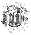
- the figures schematically show the components accommodated in the interior of a process chamber of a coating installation (not shown) which are required for coating substrate components according to the PVD method or according to the reactive PVD method.
- the assemblies shown in the figures are arranged in an evacuable and preferably provided with different gas connections coating chamber or vacuum chamber.
- Such vacuum chambers are known, so that can be dispensed with a detailed description of this chamber here.
- the peculiarity of the coating system to be described in detail below is how the interior of the evacuatable deposition or treatment chamber can be equipped to significantly increase the efficiency in the operation of such a system and to minimize the process times of the system due to improved flexibility.
- coating and / or treatment modules 12 are arranged at predetermined angular intervals. These coating and / or treatment modules 12 are formed, for example, by evaporators or so-called sputtering cathodes with modularly populated targets, wherein in addition - so-called shutters - not shown in detail - could be used. Such coating or treatment modules are known per se, so that a more detailed description of these components is unnecessary here. It should be emphasized, however, that the present invention is not limited to specific treatment / coating modules. Rather, all units regularly used in the coating process according to the PVD method can be used. In addition to the coating / treatment modules 12 heating units 14 are additionally provided, which are usually arranged between the treatment modules 12 and can also be designed as modules.
- etching anode denoted by 16 which interacts with a central filament cathode not shown in detail above which lie above the coating modules 12 and heating units 14 in the region of the dome of the coating chamber (not shown).
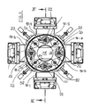
- Fig. 1 shows the arrangement of the modules required for the coating or treatment with the deposition or treatment chamber open, while in the plan view according to Fig. 2 the arrangement is shown with the chamber closed. It follows from this illustration that part of the coating modules 12 and heating units 14 grouped around the assembly table 10 can be mounted on a separate component which serves as a loading door for the vacuum chamber. The remaining coating and heating modules are mounted on a support structure which - just like the loading door - has mounting points for the flexible arrangement of the coating and heating modules.
- the mounting table 10 is designed as a kind of carousel and he wears - as best of the Fig. 2 It can be seen - a plurality of, that is, in the illustrated embodiment 8, preferably identically designed mounting positions 18-1 to 18-8, which can be equipped individually with different modules.
- Each mounting place 18-1 to 18-8 is associated with a drive shaft 22, each having a vertical axis of rotation.
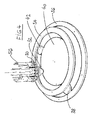
- the drive shaft 22 is rotatably coupled to a vertical support shaft 24, the turntable 26 in predetermined and preferably adjustable axial distances with plug-in receptacles 30 for supporting substrate components, such as eg boring tools.
- the plug-in receptacles are designed so that the drilling tools project with the surface sections to be coated or treated from the plug receptacle.
- the support shaft 24 is stabilized.
- the plug-in receptacles and thus also the substrate components when turning the turntable 26 perform a same or counter-rotating rotation about the also vertical axis of the plug-receptacle.
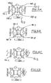
- FIG. 4 is schematically based on one of the representation of FIGS. 1 to 3 slightly modified kinematics indicated how the rotational movement of the mounting table 10 and the drive shafts 22 can be transmitted.
- a drive gear 32 which is in mesh with the internal teeth of a first ring gear 34.
- the ring gear 34 is rotatably connected to an axially offset, larger diameter second ring gear 36 which can be driven via its internal teeth by means of a first drive pinion 38.
- the drive gear 32 supporting shaft 22 extends rotatably supported by the mounting table 10 therethrough and is rotatably mounted in a likewise below the mounting table 10 lying gear 40 which is driven via a second drive pinion 42.
- the gear 40 takes the drive shafts 22 and thus the mounting table 10 in the direction of rotation with. In this way, the mounting table 10 can be clocked.
- the drive gears 32 roll on the internal teeth of the first ring gear 34.
- the rotational speed of the first ring gear 34 can be kept as large as the rotational speed of the gear 40, so that during the clock movement of the mounting table 10, a rotation of the drive shafts 22 is omitted.
- the assembly sites 18-1, 18-3, 18-5, and 18-7 are different from the assembly sites 18-2, 18-4, 18-6, and 18-8. They carry a cover plate 44 which has a holder 46 for a radially aligned shielding plate 48 above the covered drive shaft 22. Between the two adjacent shielding plates 48 of the assembly stations 18-1 and 18-7 or 18-3 and 18-5, a further, stationarily mounted Ablewandan whatsoever 50 is provided, each of which is formed by a convex sheet 52 and a secant sheet 54 and the shields the space between the adjacent radial shield plates 48 to the adjacent mounting locations. Also, the shielding plates 48 and the Ablewandanowskiowski extract 50 are designed as modules and they can - depending on the arrangement of the other treatment / coating components are mounted at different locations in the interior of the coating chamber.
- a drive device with which the relative position between the substrate carriers 26 and the coating and / or treatment units 12 is variable with closed deposition or treatment chamber, there is the possibility of the coating system even if only a few substrate components be provided with a specific coating or subjected to a specific treatment to operate economically.
- the coating and / or treatment units 12 such as evaporator, cathodes, targets, magnetrons, filament cathode and etching anode and the shielding 48, 50 of modules in the deposition or treatment chamber according to a desired coating or treatment program for the Substrate components are assembled and, accordingly, the substrate carrier 26 are equipped with those substrate components to be subjected to the same treatment.
- the deposition or treatment chamber can be closed, after which the individual treatment or coating programs for the substrate components grouped together on the substrate carriers (26) can be run through in one batch.
- a multiple heating and cooling of the substrate components and substrate support can be omitted, whereby process time can be saved to a considerable extent and the utilization of the coating system can be greatly increased even for small batches.
- the process phases of pumping, heating and cooling are the same for all substrate carriers, the assembly table 10 or the carousel rotates about its axis.
- the carousel 10 stops and the substrate carriers 26 at positions 4 and 8 rotate about their own axis.
- the etching phase can begin ( FIG. 5A ).
- Positions 4 and 8 rotate about their own axis, and the right and left vaporizers TiAl and Ti associated with these positions are ignited, and if present, after burnout (if possible), a shutter not shown in detail is opened , Position 4 is - after building a suitable nitrogen atmosphere - coated with titanium nitride and position 8 with titanium aluminum nitride. Depending on the layer thickness achieved, the evaporators are switched off and / or the associated shutter is closed. The drive continues to clock in the position according to FIG. 5D ,
- positions 2 and 6 can be coated with a nano-layer. If positions 2 and 6 reach the evaporator required for the next layer, the corresponding evaporator and / or the shutter, if present, will open. The respective situation can be separated. The position then rotates again about its own axis.
- Each position can be coated individually or simultaneously by different evaporators.
- Abschottmodule instead of the positionable at the assembly stations Abschottmodule also Abschott stylesen can be used, either radially or axially in inserted the interior of the treatment chamber, and or moved and / or erect.
- a kinematic reversal can take place in the region of the drive for the substrate carriers, so that the assembly table remains stationary and the treatment / coating units are driven.
- etching anode instead of the etching anode, it is also possible to use other functional units for the pretreatment of the substrate in the coating chamber, whereby the spatial arrangement of these functional units, for example due to the process, can vary within wide limits.
- the drive kinematics for providing the required relative movements between the substrate components and the coating or treatment units can be freely varied. The only thing that matters is that the drive is able to subject the mounting table, the substrate carrier and advantageously also the holder for the individual substrate components of a relative rotational movement with respect to the treatment units.
- Another possibility of operation is that the coating process is shortened by only selected substrate carriers loaded and thus the system is charged only with a reduced amount and in the treatment only the sector is heated in which a treatment or coating is to be made.
- the invention thus provides a device for surface treatment and / or coating of substrate components by deposition from the gas phase, in particular by physical vapor deposition after the PVD (Physical Vapor Deposition) or reactive PVD process.
- PVD Physical Vapor Deposition
- a plurality of substrate carriers and a plurality of coating and / or treatment units such as evaporator sources, cathodes, targets, magnetrons, filament cathode and etching anode are arranged.
- evaporator sources, cathodes, targets, magnetrons, filament cathode and etching anode are arranged.
- it can be equipped in such a modular manner that the substrate components introduced into the plant in a batch can be subjected to a different treatment (coating, surface treatment).
Description
Die Erfindung betrifft eine Vorrichtung und ein Verfahren zur Oberflächenbehandlung und/oder -beschichtung von Substratkomponenten durch Abscheidung aus der Gasphase, insbesondere durch physikalische Abscheidung aus der Gasphase nach dem PVD- (Physical Vapour Deposition) oder dem reaktiven PVD-Verfahren, gemäß dem Oberbegriff des Patentanspruchs 1 bzw. des Patentanspruchs 14. Mit derartigen Verfahren bzw. mit solchen Vorrichtungen gelingt es, auf Werkstückoberflächen, d.h. auf Substratkomponenten sehr dünne Schichten, beispielsweise Korrosions- oder Verschleißschutzschichten, wie z. B. Hartstoffschichten beispielsweise auf Titanbasis, aufzubringen. Derartige Dünnschichten finden häufig bei der Werkzeugproduktion, insbesondere bei der Produktion von spanabhebenden Präzisionswerkzeugen, wie z. B. Bohr-, Fräs- oder Reibwerkzeugen Anwendung.The invention relates to a device and a method for surface treatment and / or coating of substrate components by deposition from the gas phase, in particular by physical vapor deposition after the PVD (Physical Vapor Deposition) or the reactive PVD method, according to the preamble of Patent claim 1 or
Während beim CVD- (Chemical Vapour Deposition) Verfahren mit verhältnismäßig hohen Prozesstemperaturen von 900 bis 1100°C gearbeitet wird, können beim PVD-Prozess die Prozesstemperaturen wesentlich niedriger, d.h. bei etwa 100 bis 600°C liegen. Nach diesem Verfahren wird der Beschichtungswerkstoff zunächst durch Anwendung eines geeigneten physikalischen Effekte, wie z. B. durch einen Elektronenstrahl, einen Lichtbogen (Arc-PVD) oder durch Kathodenzerstäubung verdampft. Das verdampfte Material trifft dann auf die Substratoberfläche auf, wo es zur Schichtbildung kommt. Damit die Dampfteilchen das Substrat erreichen, muß mit Unterdruck gearbeitet werden. Bei diesem Prozess liegt eine geradlinige Teilchenbewegung vor, so dass das Substrat bewegt werden muß, damit die gesamte Substratoberfläche gleichmäßig und homogen beschichtet werden kann.While the CVD (Chemical Vapor Deposition) process operates at relatively high process temperatures of 900 to 1100 ° C, the process temperatures in the PVD process can be much lower, i. be at about 100 to 600 ° C. According to this method, the coating material is first by applying a suitable physical effects, such. B. by an electron beam, an arc (Arc-PVD) or sputtered by sputtering. The vaporized material then impinges on the substrate surface, where it comes to film formation. In order for the vapor particles to reach the substrate, it is necessary to work with negative pressure. In this process, there is a linear particle movement, so that the substrate must be moved so that the entire substrate surface can be uniformly and homogeneously coated.
Die beim PVD-Verfahren niedrigeren Prozesstemperaturen werden allerdings mit einem größeren vorrichtungstechnischen Aufwand erkauft. Denn die zu beschichtenden Substrate müssen - um zu einer guten Schichthaftung zu gelangen - einer sorgfältigen Oberflächenvorbehandlung und einer genauen Prozessführung unterworfen werden. Darüber hinaus muss dafür gesorgt werden, dass sogenannte Abschattungseffekte kompensiert werden. Deshalb müssen einschlägige PVD-Beschichtungsanlagen mit einer Antriebstechnik zur kontinuierlichen Bewegung der Substratkomponenten während des Beschichtungs- bzw. Oberflächenbehandlungsvorgangs ausgestattet werden. Weil das Auf- oder Bedampfen darüber hinaus im Hochvakuum, d.h. im Bereich von 10-4 bis 10 Pa, erfolgt, die Behandlungskammer also hermetisch nach außen abgeschlossen werden muss, ergibt sich hierdurch ein verhältnismäßig komplexer Aufbau der Beschichtungsanlage.However, the process temperatures which are lower in the case of the PVD process are purchased at a greater expense in terms of device technology. Because the substrates to be coated must - in order to arrive at a good layer adhesion - a careful Surface pretreatment and a precise litigation are subjected. In addition, care must be taken that so-called shadowing effects are compensated. Therefore, relevant PVD coating equipment must be equipped with a drive technique for continuously moving the substrate components during the coating or surface treatment process. Moreover, because the evaporation or vapor deposition takes place in a high vacuum, ie in the range of 10 -4 to 10 Pa, the treatment chamber has to be hermetically sealed to the outside, resulting in a relatively complex construction of the coating system.
Um die Beschichtungsmaterialien, wie z.B. Metalle in die Gasphase überzuführen, werden nach dem PVD-Verfahren verschiedene Wege eingeschlagen, wie z.B. das Kathodenzerstäuben bzw. das Sputtern, einschließlich des Magnetron-Sputterns, das Ionenplattieren, einschließlich des reaktiven Ionenplattierens, oder das das Laserverdampfen oder das Vakuumverdampfen. Allen Verfahren ist gemeinsam, dass zur Erzielung des gewünschten Beschichtungs- bzw. Behandlungseffekts die Prozessparameter wie Gasatmosphäre, Temperatur und Ausrichtung der Substratoberfläche zum Beschichtungsmaterial sehr genau eingehalten werden müssen. Deshalb sind herkömmliche Beschichtungsanlagen so aufgebaut worden, dass die Behandlungskammer Platz für mehrere Substratträger und Beschichtungs- und/oder Behandlungseinheiten wie z. B. Verdampferquellen, Kathoden, Targets, Magnetrons, usw., bietet. Solche Vakuumbehandlungsanlagen sind z. B. in der
Mit solchen marktüblichen Anlagen können die zu beschichtenden bzw. zu behandelnden Substrate mit nur einer einzigen Schichtart versehen werden. Auch wenn diese Schichtart eine mehrlagige Schicht ist, wie sie beispielsweise im Dokument
Dies führt dazu, dass herkömmliche Beschichtungsanlagen, oftmals nur unwirtschaftlich betrieben werden können. Denn die prozentual meiste Prozesszeit bei den eingangs beschriebenen Beschichtungs- und/oder Behandlungsanlagen nach dem PVD-Verfahren wird beim Aufheizen und Abkühlen der Substrate und deren Haltevorrichtungen verbraucht. Weil darüber hinaus bei vielen Beschichtungs-Zentren das Spektrum der zu beschichtenden Substratkomponenten breit gefächert ist, werden für die unterschiedlichen Substratkomponenten auch unterschiedliche Schichten verlangt. Da das Volumen der Beschichtungsanlage aufgrund der Abmessungen des Beschichtungskessels feststeht, die Anzahl der Substrate bzw. Substratkomponenten, die eine bestimmte Schichtart verlangen, oftmals nicht ausreicht, um eine Beschichtungsanlage zu 100% zu füllen, können letztlich die geforderten Lieferzeiten nicht eingehalten werden.As a result, conventional coating systems can often only be operated uneconomically. Because the percentage of most process time in the coating and / or treatment plants according to the PVD process described above is consumed during heating and cooling of the substrates and their holding devices. In addition, because in many coating centers, the spectrum of substrate components to be coated is broad, also different layers are required for the different substrate components. Since the volume of the coating system is fixed due to the dimensions of the coating vessel, the number of substrates or substrate components that require a certain layer type is often not sufficient to fill a coating system to 100%, ultimately the required delivery times can not be met.
Das Dokument
Der Erfindung liegt deshalb eine Vorrichtung zur Oberflächenbehandlung und/oder -beschichtung von Substratkomponenten durch Abscheidung aus der Gasphase, insbesondere durch physikalische Abscheidung aus der Gasphase nach dem PVD-Verfahren, sowie ein Verfahren zum Betreiben einer derartigen Vorrichtung bereitzustellen, mit der bzw. mit dem es gelingt, die Prozess- und Lieferzeiten zu minimieren.The invention is therefore an apparatus for surface treatment and / or coating of substrate components by deposition from the gas phase, in particular by physical vapor deposition by the PVD method, and a method for operating such a device to provide, with or with the it succeeds in minimizing the process and delivery times.
Diese Aufgabe wird hinsichtlich der Vorrichtung durch die Merkmale des Anspruchs 1 und hinsichtlich des Verfahrens durch die Verfahrensschritte des Anspruchs 13 gelöst, wobei es gelingt, die Prozesszeiten zusätzlich dadurch zu verkürzen, dass verschiedene Behandlungen der Substratkomponenten gleichzeitig ablaufen können.This object is achieved with regard to the device by the features of claim 1 and with respect to the method by the method steps of claim 13, wherein it is possible to additionally shorten the process times that different treatments of the substrate components can take place simultaneously.
Erfindungsgemäß wird die Vorrichtung so aufgebaut, dass sie mit Modulen bestückt werden kann, und zwar derart, dass die in einer Charge in dieAccording to the invention, the device is constructed so that it can be equipped with modules, in such a way that in a batch in the
Beschichtungsvorrichtung eingebrachten Substratkomponenten nach dem Schließen des Beschichtungs-/Behandlungsraums einer unterschiedlichen Behandlung, d.h. einer Beschichtung oder einer Oberflächenbehandlung, unterzogen werden können. Durch die erfindungsgemäße Gestaltung der Vorrichtung den Auslastungsgrad der Beschichtungsanlage erheblich zu steigern und darüber hinaus die Beschichtungsanlage wesentlich wirtschaftlicher und mit stark verbesserter Energieeffizienz zu betreiben. Denn die erfindungsgemäß größere Anzahl von Substratkomponenten in der Beschichtungsanlage ist nur einmal aufzuheizen und abzukühlen, wodurch Prozesszeit in erheblichem Umfang eingespart wird.Coating device introduced substrate components after closing the coating / treatment space of a different treatment, i. a coating or a surface treatment can be subjected. The inventive design of the device to increase the utilization rate of the coating system considerably and also to operate the coating system much more economical and with greatly improved energy efficiency. Because the inventively larger number of substrate components in the coating system is only once to heat and cool, thereby process time is saved to a considerable extent.
Das erfindungsgemäße Verfahren ist im Kern dadurch gekennzeichnet, dass Beschichtungs- und/oder Behandlungseinheiten sowie Abschirmmodule entsprechend einem gewünschten Beschichtungs- und/oder Behandlungsprogramm für unterschiedlich zu beschichtende Substratkomponenten zusammengestellt werden, und dass dann die Substratträger mit denjenigen Substratkomponenten bestückt werden, die in einer Charge derselben Behandlung unterzogen werden sollen. Nach dem Schließen der Behandlungskammer sorgen dann die Abschirmmodule und die Prozesssteuerung der Anlage dafür, dass die auf den einzelnen Substratträgern zusammengefassten Substratkomponenten einem individuellen Beschichtungs- und/oder Behandlungsprogramm unterzogen werden. Dabei kann gemäß einer Weiterbildung des Verfahrens eine unterschiedliche Behandlung der Substratkomponenten an verschiedenen Orten der Beschichtungskammer sogar gleichzeitig erfolgen.The method according to the invention is characterized in that coating and / or treatment units and shielding modules are assembled according to a desired coating and / or treatment program for substrate components to be coated differently, and then the substrate carriers are loaded with those substrate components which are in a batch should be subjected to the same treatment. After closing the treatment chamber, the shielding modules and the process control of the system then ensure that the substrate components combined on the individual substrate carriers are subjected to an individual coating and / or treatment program. In this case, according to a further development of the method, a different treatment of the substrate components at different locations of the coating chamber can take place simultaneously.
Aufgrund des modularen Aufbaus der Anlage ist es möglich, die Beschichtungsanlage äußerst flexibel an die jeweils vorliegende Auftragslage anzupassen. Dabei ergibt sich der zusätzliche Vorteil, dass die Anlage selbst dann, wenn nur eine Mindermenge chargiert wird, wirtschaftlich betrieben werden kann, indem innerhalb der Behandlungskammer Bereiche geschaffen werden können, die individuell und abgeschirmt von anderen Bereichen der Behandlungskammer aufgeheizt und abgekühlt werden können und in denen unter Abschirmung von weiteren Bereichen der Kammer ein bestimmtes Beschichtungs- und/oder Ätzprogramm durchgeführt werden kann.Due to the modular structure of the plant, it is possible to adapt the coating system extremely flexibly to the respective order situation. This results in the additional advantage that the system even if only a small amount is charged, can be operated economically by within the treatment chamber areas can be created that can be heated individually and shielded from other areas of the treatment chamber and cooled in and which under shielding of other areas of the chamber, a specific coating and / or etching program can be performed.
Dabei wird erfindungsgemäß der vorhandene Bauraum der Behandlungskammer in vorteilhafter Weise ausgenutzt, wobei sich der zusätzliche Vorteil ergibt, dass die unterschiedlichen Behandlungen der Substratkomponenten aufgrund der räumlichen Trennung der Behandlungsstationen gleichzeitig ablaufen können. Außerdem wird dadurch die Möglichkeit eröffnet, unterschiedliche Substratträger vor ausgewählten Beschichtungs- und/oder Behandlungseinheiten einer individuellen Behandlung mit genau kontrollierten Prozessparametern zu unterziehen, ohne durch benachbarte Beschichtungs- und/oder Behandlungseinheiten beeinflusst zu werden. Dadurch gelingt es, eine sehr genaue und homogene Aufwachsrate der Schicht zu erzielen.In this case, according to the invention, the available installation space of the treatment chamber is advantageously utilized, with the additional advantage that the different treatments of the substrate components can take place simultaneously due to the spatial separation of the treatment stations. In addition, will This opens up the possibility of subjecting different substrate carriers before selected coating and / or treatment units to individual treatment with precisely controlled process parameters without being influenced by adjacent coating and / or treatment units. This makes it possible to achieve a very accurate and homogeneous growth rate of the layer.
Durch die Abschirmeinrichtung nach Anspruch 2, die vorzugsweise wiederum als Modul ausgebildet wird, gelingt es, wertvollen Baumraum einzusparen, denn mittels der Abschirmmodule lassen sich Substratkomponenten selbst auf engstem Bauraum einer unterschiedlichen Behandlung unterziehen.By the shielding device according to claim 2, which is preferably in turn formed as a module, it is possible to save valuable tree space, because by means of the shielding module substrate components can be subjected to different treatment even in the smallest space.
Es hat sich gezeigt, dass es für PVD-Beschichtungsanlagen ohne weiteres genügt, die Abschirmmodule in Form einer Trennwandkonfiguration nach Anspruch 3 auszubilden, ohne eine Qualitätsminderung der Oberflächenbehandlung bzw. -beschichtung in Kauf nehmen zu müssen. Die Trennwände können aus unterschiedlichem Material bestehen, einschließlich Keramik- und/oder Lochblechmaterial.It has been found that it is readily sufficient for PVD coating systems to form the shielding modules in the form of a partition wall configuration according to claim 3, without having to accept a reduction in the quality of the surface treatment or coating. The partitions may be made of different materials, including ceramic and / or perforated sheet material.
Die Flexibilität der Anlage wird dadurch zusätzlich gesteigert, wenn gemäß Anspruch 4 eine Kinematik vorgesehen wird, mit der die Relativlage zwischen den Substratträgern und den Beschichtungs- und/oder Behandlungseinheiten und/oder Heizeinrichtungen bei geschlossener Abscheidungs- bzw. Behandlungskammer verändert werden kann.The flexibility of the system is thereby further increased if, according to claim 4, a kinematics is provided, with which the relative position between the substrate carriers and the coating and / or treatment units and / or heaters can be changed in a closed deposition or treatment chamber.
Es ist grundsätzlich möglich, die Beschichtungs- und/oder Behandlungseinheiten zusammen mit der Trägerkonstruktion mit einem Antrieb zu versehen. Die Kinematik wird jedoch einfacher, wenn ein Montagetisch gemäß Anspruch 8 mit einem Drehantrieb ausgestattet wird.It is basically possible to provide the coating and / or treatment units together with the support structure with a drive. However, the kinematics becomes easier when a mounting table according to
Vorteilhafterweise wird die Drehantriebseinrichtung für den Montagetisch gleichzeitig als Indexiereinrichtung zur Positionierung ausgewählter Substratträger gegenüber ausgewählten Beschichtungs- und/oder Behandlungseinheiten herangezogen, wodurch der steuerungstechnische Aufwand kleiner wird.Advantageously, the rotary drive device for the assembly table is simultaneously used as an indexing device for positioning selected substrate carriers with respect to selected coating and / or treatment units, as a result of which the complexity of the control technology becomes smaller.
Vorteilhafterweise ist - vorzugsweise in Verbindung mit der Ausgestaltung gemäß Anspruch 9 - an jedem Montageplatz des Montagetischs ein Drehantrieb, beispielsweise in Form einer Welle, für einen Substratträger vorgesehen. Es ist auf diese Weise möglich, die Beschichtungsanlage bei 100%iger Füllung mit gleichmäßig zu beschichtenden Substratelementen auf herkömmliche Weise zu betreiben, ohne die vorstehend beschriebene Flexibilität der Anlage zu verlieren.Advantageously - preferably in conjunction with the embodiment according to claim 9 - a rotary drive, for example in the form of a shaft, provided for a substrate carrier at each mounting location of the assembly table. It is possible in this way, the coating system at 100% filling with even To operate to be coated substrate elements in a conventional manner, without losing the flexibility of the system described above.
Mit der Modifikation des Anspruchs 10 kann z.B. ein ausgewählter Substratträger in unmittelbarer Nachbarschaft zu einer Beschichtungs- und/oder Behandlungseinheit in Drehbewegung versetzt werden, ohne den Taktbetrieb zu betätigen, wodurch es gelingt, auf diesen ausgewählten Substratkomponenten eine äußerst homogene und in ihrer Dicke genau definierte Schicht abzuscheiden.With the modification of
Grundsätzlich ist es möglich, ausgewählte Beschichtungs- und/oder Behandlungseinheiten nacheinander in Funktion zu setzen. Der erfindungsgemäße Aufbau der Beschichtungsanlage erlaubt es jedoch auch, ausgewählte Beschichtungs- und/oder Behandlungseinheiten synchron zu betreiben, wodurch weitere Prozesszeit eingespart wird.In principle, it is possible to set selected coating and / or treatment units successively in operation. However, the coating system according to the invention also makes it possible to operate selected coating and / or treatment units synchronously, thereby saving further processing time.
Nachstehend werden anhand schematischer Zeichnungen Ausführungsbeispiele der Erfindung näher erläutert. Es zeigen:
-
Fig. 1 eine perspektivische Ansicht des Innenraums einer Beschichtungsanlage bei abgenommener Beschichtungskammerwandung; -
Fig. 2 schematisch die Draufsicht der Beschichtungsanlage gemäßFig. 1 bei geschlossener Beschichtungskammer; -
Fig. 3 eine schematische Schnittansicht der Beschichtungsanlage gemäßFig. 2 bei einer Schnittführung entsprechend III-III inFig. 2 ; -
Fig. 4 eine perspektivische schematische Ansicht ausgewählter Antriebskomponenten der erfindungsgemäßen Beschichtungsanlage; und -
Fig. 5A bis 5D Schaubilder zur Darstellung unterschiedlicher Montagetisch-Positionen bei der Durchführung des erfindungsgemäßen Verfahrens.
-
Fig. 1 a perspective view of the interior of a coating plant with removed coating chamber wall; -
Fig. 2 schematically the top view of the coating system according toFig. 1 with closed coating chamber; -
Fig. 3 a schematic sectional view of the coating system according toFig. 2 in a cut according to III-III inFig. 2 ; -
Fig. 4 a perspective schematic view of selected drive components of the coating system according to the invention; and -
Figs. 5A to 5D Schaubilder showing different assembly table positions in the implementation of the method according to the invention.
In den Figuren sind schematisch die im Inneren einer nicht näher dargestellten Prozesskammer einer Beschichtungsanlage aufgenommen Komponenten dargestellt, die zur Beschichtung von Substratkomponenten nach dem PVD-Verfahren bzw. nach dem reaktiven PVD-Verfahren benötigt werden. Mit anderen Worten, die in den Figuren gezeigten Baugruppen sind in einer evakuierbaren und vorzugsweise mit verschiedenen Gasanschlüssen versehenen Beschichtungskammer bzw. Vakuumkammer angeordnet. Derartige Vakuumkammern sind bekannt, sodass auf eine genaue Beschreibung dieser Kammer hier verzichtet werden kann. Die Besonderheit der nachfolgend näher zu beschreibenden Beschichtungsanlage besteht darin, wie das Innere der evakuierbaren Abscheidungs- bzw. Behandlungskammer bestückt werden kann, um die Wirtschaftlichkeit beim Betrieb einer solchen Anlage erheblich anzuheben und aufgrund verbesserter Flexibilität die Prozesszeiten der Anlage zu minimieren.The figures schematically show the components accommodated in the interior of a process chamber of a coating installation (not shown) which are required for coating substrate components according to the PVD method or according to the reactive PVD method. In other words, the assemblies shown in the figures are arranged in an evacuable and preferably provided with different gas connections coating chamber or vacuum chamber. Such vacuum chambers are known, so that can be dispensed with a detailed description of this chamber here. The peculiarity of the coating system to be described in detail below is how the interior of the evacuatable deposition or treatment chamber can be equipped to significantly increase the efficiency in the operation of such a system and to minimize the process times of the system due to improved flexibility.
Zu diesem Zweck wird ein modularer Aufbau der Beschichtungsvorrichtung gewählt. Um einen mit 10 bezeichneten Montagetisch herum sind in vorbestimmten Winkelabständen Beschichtungs- und/oder Behandlungsmodule 12 angeordnet. Diese Beschichtungs- und/oder Behandlungsmodule 12 sind beispielsweise von Verdampfer oder sogenannten Sputter-Kathoden mit modular bestückbaren Targets gebildet, wobei zusätzlich - nicht näher gezeigte - sogenannte Shutter zur Anwendung kommen könnten. Derartige Beschichtungs- bzw. Behandlungsmodule sind an sich bekannt, so dass sich eine genauere Beschreibung dieser Komponenten hier erübrigt. Es soll aber hervorgehoben werden, dass die vorliegende Erfindung nicht auf spezielle Behandlungs-/Beschichtungsmodule beschränkt ist. Es können vielmehr alle beim Beschichtungsprozess nach dem PVD-Verfahren regelmäßig zur Anwendung kommenden Einheiten verwendet werden. Neben den Beschichtungs-/Behandlungsmodulen 12 sind zusätzlich Heizeinheiten 14 vorgesehen, die in der Regel zwischen den Behandlungsmodulen 12 angeordnet sind und ebenfalls als Module ausgeführt sein können.For this purpose, a modular construction of the coating device is selected. Around a mounting table labeled 10, coating and / or
Im Zentrum des Montagetischs 10 befindet sich eine mit 16 bezeichnete Ätzanode mit einer in den Figuren nicht näher dargestellten zentralen Filamentkathode zusammenwirkt, welche oberhalb der Beschichtungsmodule 12 und Heizeinheiten 14 im Bereich der nicht dargestellten Kuppel der Beschichtungskammer zu liegen.In the center of the assembly table 10 there is an etching anode denoted by 16 which interacts with a central filament cathode not shown in detail above which lie above the
Der Montagetisch 10 ist als eine Art Karussell ausgebildet und er trägt - wie am besten aus der
Jedem Montageplatz 18-1 bis18-8 ist eine Antriebswelle 22 zugeordnet, die jeweils eine vertikale Drehachse hat. Bei den Montageplätzen 18-2, 18-4, 18-6 und 18-8 ist die Antriebswelle 22 drehfest mit einer vertikalen Trägerwelle 24 gekoppelt, die in vorbestimmten und vorzugsweise einstellbaren Axialabständen Drehteller 26 mit Steck-Aufnahmen 30 zur Halterung von Substratkomponenten, wie z.B. von Bohrwerkzeugen trägt. Die Steck-Aufnahmen sind so ausgeführt, dass die Bohrwerkzeuge mit den zu beschichtenden bzw. zu behandelnden Oberflächenabschnitten aus der Steck-Aufnahme vorstehen.Each mounting place 18-1 to 18-8 is associated with a
Mittels einer Stützstange 20 und eines Stützarms 28 wird die Trägerwelle 24 stabilisiert. Über ein nicht näher gezeigtes Getriebe kann dafür gesorgt werden, dass die Steck-Aufnahmen und damit auch die Substratkomponenten bei Drehung der Drehteller 26 eine gleich- oder gegengerichtete Eigendrehung um die ebenfalls vertikale Achse der Steck-Aufnahme ausführen.By means of a
In
Die das Antriebszahnrad 32 tragende Welle 22 erstreckt sich drehbar gelagert durch den Montagetisch 10 hindurch und sitzt drehbar in einem ebenfalls unterhalb des Montagetischs 10 liegenden Zahnrad 40, das über ein zweites Antriebsritzel 42 antreibbar ist.The
Wenn somit das zweite Antriebsritzel 42 angetrieben wird, nimmt das Zahnrad 40 die Antriebswellen 22 und damit den Montagetisch 10 in Drehrichtung mit. Auf diese Weise kann der Montagetisch 10 getaktet werden.Thus, when the
Gleichzeitig wälzen die Antriebszahnräder 32 an der Innenverzahnung des ersten Ringrads 34 ab. Durch geeignete Steuerung des Drehantriebs des ersten Antriebsritzels 38 kann die Drehzahl des ersten Ringrads 34 ebenso groß wie die Drehzahl des Zahnrads 40 gehalten werden, so dass während der Taktbewegung des Montagetischs 10 eine Drehung der Antriebswellen 22 unterbleibt.At the same time, the drive gears 32 roll on the internal teeth of the
Wenn demgegenüber der Antrieb des zweiten Antriebsritzels 42 angehalten wird und der Montagetisch indexiert bleibt, können durch Ansteuerung des ersten Antriebsritzels38 alle Antriebswellen 22 gleichzeitig in Drehbewegung versetzt werden.In contrast, when the drive of the
Einige der Montageplätze, d.h. die Montageplätze 18-1, 18-3, 18-5 und 18-7 sind unterschiedlich zu den Montageplätzen 18-2, 18-4, 18-6 und 18-8 bestückt. Sie tragen eine Abdeckplatte 44, die oberhalb der abgedeckten Antriebswelle 22 eine Halterung 46 für ein radial ausgerichtetes Abschirmblech 48 aufweist. Zwischen den beiden benachbarten Abschirmblechen 48 der Montageplätze 18-1 und 18-7 bzw. 18-3 und 18-5 ist jeweils eine weitere, stationär montierte Abschirmwandanordnung 50 vorgesehen, die jeweils von einem konvexen Blech 52 und einem Sekantenblech 54 gebildet ist und die den Raum zwischen den benachbarten radialen Abschirmblechen 48 zu den benachbarten Montageplätzen abschirmt. Auch die Abschirmbleche 48 und die Abschirmwandanordnungen 50 sind als Module ausgestaltet und sie können - je nach Anordnung der übrigen Behandlungs-/Beschichtungskomponenten an unterschiedlichen Stellen im Inneres der Beschichtungskammer montiert werden.Some of the assembly sites, ie, the assembly sites 18-1, 18-3, 18-5, and 18-7 are different from the assembly sites 18-2, 18-4, 18-6, and 18-8. They carry a cover plate 44 which has a
Mit dem vorstehend beschriebenen Aufbau der Beschichtungsanlage ergibt sich folgender Effekt:
- Nicht nur die Substratträger 2, sondern auch die Beschichtungs- und/
oder Behandlungseinheiten 12, wie z.B. die Verdampferquellen, Kathoden, Targets, Magnetrons, Filamentkathode(n) und die Ätzanode sowie dieHeizmodule 14 können modular zusammengestellt und derart angeordnet werden, dass die in einer Charge in die Anlage eingebrachten Substratkomponenten in der Beschichtungs- und Behandlungskammer einer unterschiedlichen Behandlung (Beschichtung, Oberflächenbehandlung) unterzogen werden können. Im Einzelnen können die Substratkomponenten, wie z.B. unterschiedliche Bohrwerkzeuge, die auf unterschiedlichen Substratträgern zusammengefasst sind, der unterschiedlichen Behandlung an verschiedenen Orten in der Abscheidungs- bzw. -behandlungskammer unterzogen werden, wobei über dieAbschirmbleche 48 und die Abschirmwandanordnung 50 zumindest die auf einem Substratträger 26 angeordneten Substratkomponenten 56 ausschließlich im Einflussbereich einer ganz bestimmten Beschichtungs- und/oder Behandlungseinheit 12 gehalten werden.
- Not only the substrate carriers 2, but also the coating and / or
treatment units 12, such as the evaporator sources, cathodes, targets, magnetrons, filament cathode (s) and the etching anode and theheating modules 14 can be modularly arranged and arranged such that the in a batch in the plant introduced substrate components in the coating and treatment chamber of a different treatment (coating, surface treatment) can be subjected. In detail, the substrate components, such as different drilling tools, which are combined on different substrate carriers, the different treatment at different locations in the deposition or -behandlungskammer be subjected, wherein on theAbschirmbleche 48 and the Abschirmwandanordnung 50 at least on a substrate carrier 26th arrangedsubstrate components 56 are held exclusively in the sphere of influence of a very specific coating and / ortreatment unit 12.
Weil darüber hinaus eine Antriebsvorrichtung vorgesehen ist, mit der die Relativlage zwischen den Substratträgern 26 und den Beschichtungs- und/oder Behandlungseinheiten 12 bei geschlossener Abscheidungs- bzw. behandlungskammer veränderbar ist, ergibt sich die Möglichkeit, die Beschichtungsanlage selbst dann, wenn jeweils nur wenige Substratkomponenten mit einer spezifischen Beschichtung versehen oder einer spezifischen Behandlung unterzogen werden müssen, wirtschaftlich zu betreiben. Denn es können die Beschichtungs- und/oder Behandlungseinheiten 12, wie z.B. Verdampfer, Kathoden, Targets, Magnetrons, Filamentkathode und Ätzanode sowie die Abschirmelemente 48, 50 aus Modulen in der Abscheidungs- bzw. behandlungskammer entsprechend einem gewünschten Beschichtungs- bzw. Behandlungsprogramm für die Substratkomponenten zusammengestellt werden und dementsprechend die Substratträger 26 mit denjenigen Substratkomponenten bestückt werden, die derselben Behandlung unterzogen werden sollen. Anschließend kann die Abscheidungs- bzw. behandlungskammer geschlossen werden, woraufhin die individuellen Behandlungs- bzw. Beschichtungsprogramme für die in Gruppen auf den Substratträgern (26) zusammengefassten Substratkomponenten in einer Charge durchlaufen werden können. Ein mehrfaches Aufheizen und Abkühlen der Substratkomponenten und Substratträger kann entfallen, wodurch Prozesszeit in erheblichem Umfang eingespart und die Auslastung der Beschichtungsanlage auch bei kleinen Chargen stark gesteigert werden kann.In addition, because a drive device is provided, with which the relative position between the
Dies soll anhand eines Behandlungsbeispiels anhand der
- Es sei z.B. angenommen, dass in einer Charge drei verschiedene Schichtarten aufgebracht werden sollen. In diesem Fall werden - wie in
Figur 5A gezeigt - die Positionen 1,3.5 und 7 werden mit Abschottmodulen 48-1, 48-3, 48-5 und 48-7 besetzt. Auf den Positionen 2,4,6 und 8 werden Substrate chargiert.
- For example, suppose that three different types of coatings are to be applied in a batch. In this case - as in
FIG. 5A The positions 1,3,5 and 7 are occupied by barrier modules 48-1, 48-3, 48-5 and 48-7. Atpositions 2,4,6 and 8 substrates are charged.
Die Prozessphasen Pumpen, Heizen und Abkühlen sind für alle Substratträger gleich, der Montagetisch 10 bzw. das Karussell rotiert um seine Achse.The process phases of pumping, heating and cooling are the same for all substrate carriers, the assembly table 10 or the carousel rotates about its axis.
Zum Ätzen (Ionenätzen) stoppt das Karussell 10 und die Substratträger 26 an den Positionen 4 und 8 rotieren um ihre eigene Achse. Die Ätzphase kann beginnen (
Sobald das Ätzen für Position 4 und 8 abgeschlossen ist, taktet der Antrieb weiter und Position 2 und 6 werden in die Ätzposition gebracht (
Wenn die Ätzphase erfolgreich abgeschlossen ist, beginnt das Beschichten (
Jetzt können Positionen 2 und 6 mit einem nano-Layer beschichtet werden. Erreichen die Position 2 und 6 den jeweils für die nächste Lage notwendigen Verdampfer zündet der entsprechende Verdampfer und/oder der Shutter -wenn vorhanden - öffnet sich. Die jeweilige Lage kann abgeschieden werden. Die Position rotiert dann wieder um ihre eigene Achse.Now positions 2 and 6 can be coated with a nano-layer. If positions 2 and 6 reach the evaporator required for the next layer, the corresponding evaporator and / or the shutter, if present, will open. The respective situation can be separated. The position then rotates again about its own axis.
Es kann jede Position einzeln oder auch gleichzeitig von verschiedenen Verdampfern beschichtet werden.Each position can be coated individually or simultaneously by different evaporators.
Um weiterzutakten rotiert das Karussell um die eigene Achse. Sind alle Layer abgeschieden, werden die Verdampfer abgeschaltet. Die gesamte Charge wird jetzt abgekühlt, woraufhin die Beschichtungs- bzw. Behandlungskammer, d.h. der Kessel belüftet werden kann. Der Prozess ist abgeschlossen.To continue the carousel revolves around its own axis. Once all layers have been separated, the evaporators are switched off. The entire batch is now cooled, whereupon the coating or treating chamber, i. the boiler can be ventilated. The process is complete.
Dieser vorstehend beschriebene Prozess ist nur eine mögliche Variante. Je nach vorhandener Verdampferanzahl und deren Targetmaterialien, Anzahl der Positionen und abhängig von Aufbau der Abschottmodule sind verschieden viele Schichtarten in einem Prozess möglich. Auch der Füllgrad ist unmittelbar von erwähnten Bedingungen abhängig und damit variierbar. Durch den modularen Aufbau sind auch eingekürzte Prozesse möglich. Hierbei wird nur eine verminderte Anzahl Positionen chargiert und diese gezielt geheizt, vorbehandelt und beschichtet.This process described above is just one possible variant. Depending on the number of evaporators and their target materials, the number of positions and depending on the structure of the Abschottmodule different numbers of types of layers in a single process are possible. The degree of filling is directly dependent on the conditions mentioned and thus variable. Thanks to the modular structure, shortened processes are also possible. In this case, only a reduced number of positions is charged and heated specifically, pretreated and coated.
Selbstverständlich sind Abweichungen von der vorstehend beschriebenen Ausführungsform möglich, ohne den Grundgedanken zu verlassen. So können selbstverständlich auch andere Schichten, beispielsweise dekorative Schichten abgeschieden werden.Of course, deviations from the embodiment described above are possible without departing from the spirit. Thus, of course, other layers, such as decorative layers can be deposited.
Anstelle der an den Montageplätzen positionierbaren Abschottmodule können auch Abschotteinrichtungen zur Anwendung kommen, die entweder radial oder axial in den Innenraum der Behandlungskammer eingeschoben, und oder verfahren und/oder aufgerichtet werden.Instead of the positionable at the assembly stations Abschottmodule also Abschotteinrichtungen can be used, either radially or axially in inserted the interior of the treatment chamber, and or moved and / or erect.
Ferner kann beispielsweise im Bereich des Antriebs für die Substratträger eine kinematische Umkehr erfolgen, so dass der Montagetisch stationär bleibt und die Behandlungs-/Beschichtungseinheiten angetrieben werden.Furthermore, for example, a kinematic reversal can take place in the region of the drive for the substrate carriers, so that the assembly table remains stationary and the treatment / coating units are driven.
Anstelle der Ätzanode können auch andere Funktionseinheiten zur Vorbehandlung des Substrats in der Beschichtungskammer verwendet werden, wobei auch die räumliche Anordnung dieser Funktionseinheiten, beispielsweise prozessbedingt, in weiten Grenzen variieren kann.Instead of the etching anode, it is also possible to use other functional units for the pretreatment of the substrate in the coating chamber, whereby the spatial arrangement of these functional units, for example due to the process, can vary within wide limits.
Schließlich kann auch die Antriebskinematik zur Bereitstellung der erforderlichen Relativbewegungen zwischen den Substratkomponenten und den Beschichtungs- bzw. Behandlungseinheiten frei variiert werden. Entscheidend ist allein, dass der Antrieb in der Lage ist, den Montagetisch, den Substratträger und vorteilhafter Weise auch die Halter für die einzelnen Substratkomponenten einer Relativ-Drehbewegung bezüglich der Behandlungseinheiten zu unterwerfen.Finally, the drive kinematics for providing the required relative movements between the substrate components and the coating or treatment units can be freely varied. The only thing that matters is that the drive is able to subject the mounting table, the substrate carrier and advantageously also the holder for the individual substrate components of a relative rotational movement with respect to the treatment units.
Mit der beschriebenen Anordnung lässt sich auch eine Betrieb realisieren, wie er mit herkömmlichen Anlagen möglich ist. Dann tragen alle Positionen Substrate. Es sind dann aber keine Abschottmodule 48, 50 eingebaut Alle in der Charge befindlichen Substrate werden in den verschiedenen Prozessphasen vergleichbar behandelt. Es wird nur eine Schichtart abgeschieden.With the described arrangement, an operation can be realized, as it is possible with conventional systems. Then all positions carry substrates. But there are then no
Eine weitere Möglichkeit des Betriebs besteht darin, dass der Beschichtungsprozess verkürzt wird, indem nur ausgewählte Substratträger bestückt und somit die Anlage nur mit einer Mindermenge chargiert wird und bei der Behandlung nur derjenige Sektor aufgeheizt wird, in dem eine Behandlung oder Beschichtung vorgenommen werden soll.Another possibility of operation is that the coating process is shortened by only selected substrate carriers loaded and thus the system is charged only with a reduced amount and in the treatment only the sector is heated in which a treatment or coating is to be made.
Die Erfindung schafft somit eine Vorrichtung zur Oberflächenbehandlung und/oder -beschichtung von Substratkomponenten durch Abscheidung aus der Gasphase, insbesondere durch physikalische Abscheidung aus der Gasphase nach dem PVD (Physical Vapour Deposition)- oder dem reaktiven PVD-Verfahren. In einer evakuierbaren Abscheidungs- bzw. behandlungskammer sind mehrere Substratträger und mehrere Beschichtungs- und/oder Behandlungseinheiten, wie z.B. Verdampferquellen, Kathoden, Targets, Magnetrons, Filamentkathode und Ätzanode angeordnet. Zur besseren wirtschaftlichen Auslastung der Anlage ist diese derart modular bestückbar, dass die in einer Charge in die Anlage eingebrachten Substratkomponenten einer unterschiedlichen Behandlung (Beschichtung, Oberflächenbehandlung) unterzogen werden können.The invention thus provides a device for surface treatment and / or coating of substrate components by deposition from the gas phase, in particular by physical vapor deposition after the PVD (Physical Vapor Deposition) or reactive PVD process. In an evacuable deposition or treatment chamber, a plurality of substrate carriers and a plurality of coating and / or treatment units, such as evaporator sources, cathodes, targets, magnetrons, filament cathode and etching anode are arranged. For better economic utilization of the plant, it can be equipped in such a modular manner that the substrate components introduced into the plant in a batch can be subjected to a different treatment (coating, surface treatment).
Die Erfindung stellt ferner ein neues Verfahren zur Oberflächenbehandlung und/oder -beschichtung von Substratkomponenten zur Verfügung, mit dem Beschichtungsanlagen nach dem PVD (Physical Vapour Deposition)- oder dem reaktiven PVD-Verfahren wesentlich wirtschaftlicher betrieben werden können. Es ist gekennzeichnet durch folgende Verfahrensschritte:
- a) Zusammenstellen von Beschichtungs- und/oder Behandlungseinheiten (Verdampfer, Kathoden, Targets, Magnetrons, Filamentkathode und Ätzanode) sowie von Abschirmelementen aus Modulen in der Abscheidungs- bzw. behandlungskammer () entsprechend einem gewünschten Beschichtungs- bzw. Behandlungsprogramm für die Substratkomponenten;
- b) Bestückung der Substratträger mit denjenigen Substratkomponenten, die derselben Behandlung unterzogen werden sollen;
- c) Schließen der Abscheidungs- bzw. behandlungskammer; und
- d) Durchlaufen der individuellen Behandlungs- bzw. Beschichtungsprogramme für die in Gruppen auf den Substratträgern zusammengefassten Substratkomponenten in einer Charge.
- a) assembling coating and / or treatment units (evaporators, cathodes, targets, magnetrons, filament cathode and etching anode) as well as shielding elements of modules in the deposition or treatment chamber (10) according to a desired coating or treatment program for the substrate components;
- b) equipping the substrate carriers with those substrate components which are to be subjected to the same treatment;
- c) closing the deposition or treatment chamber; and
- d) passing through the individual treatment or coating programs for the summarized in groups on the substrate carriers substrate components in a batch.
Claims (14)
- A device for the surface treatment and/or coating of substrate components by deposition from the gas phase, in particular by physical deposition from the gas phase according to the PVD (physical vapor deposition) or the reactive PVD method, having a deposition or treatment chamber which can be evacuated, and in which multiple substrate carriers (26) and multiple coating and/or treatment units (12, 14, 16) (vaporizer sources, cathodes, targets, magnetrons, heating units, filament cathode, and etching anode) are situated rotatably drivable, characterized by an ability to equip the facility modularly in such a way that the substrate components (56) introduced in one batch into the facility at various locations (positions 1 to 8) within said deposition or treatment chamber can be subjected to different treatments (coating, surface treatment).
- The device according to Claim 1, characterized in that at least one shielding unit (48, 50, 52, 54) can be received in the deposition or treatment chamber, using which at least the substrate components (56) which are situated on one substrate carrier (24, 26) are kept exclusively in the influence area of a coating and/or treatment unit (12).
- The device according to Claim 2, characterized in that the shielding unit (48, 50, 52, 54) is implemented as a module and is preferably formed from planar components, such as a partition wall configuration (48, 50) which can be assembled from plates (48, 52, 54).
- The device according to one of Claims 1 to 3, characterized by a unit (10, 32 to 42), using which the relative location between the substrate carriers (24, 26) and the coating and/or treatment units (12) is changeable when the deposition or treatment chamber is closed.
- The device according to Claim 4, characterized by an installation table (10), which is received in the deposition or treatment chamber radially inside a carrier construction for the coating and/or treatment units (12, 14, vaporizer sources, cathodes, targets, magnetrons), and which has a plurality of installation spaces (18-1 to 18-8), which are equipped with a drive source (22) for the substrate carriers (24, 26), distributed over its circumference.
- The device according to Claim 5, characterized in that the installation spaces can be equipped with substrate carriers (24, 24) and/or shielding units (48, 50).
- The device according to Claim 5 or 6, characterized by a drive and indexing unit (10, 32 to 42), using which a relative rotational movement between installation table (10) and carrier construction is controllable.
- The device according to Claim 7, characterized in that the installation table (10) has a rotary drive.
- The device according to one of Claims 5 to 8, characterized in that the drive of the substrate carriers (24, 26) is discharged onto the substrate components (56).
- The device according to one of Claims 5 to 9, characterized in that the rotational movement of at least one substrate carrier is decoupled from the cyclic movement of the installation table.
- The device according to one of Claims 1 to 10, characterized in that at least selected coating and/or treatment units (12-1, 12-2) are operable synchronously.
- The device according to one of Claims 5 to 11, characterized in that the carrier construction is equipped with installation positions for the coating and/or treatment units (12) and/or heating units (14).
- A method for the surface treatment and/or coating of substrate components using deposition from the gas phase, in particular using physical deposition from the gas phase according to the PVD (physical vapor deposition) or the reactive PVD method, in which the substrate components are housed together with multiple rotatably drivable substrate carriers in a deposition or treatment chamber which can be evacuated, characterized by the following method steps:a) assembling coating and/or treatment units (12, vaporizers, cathodes, targets, magnetrons, filament cathode, and etching anode) and/or heating units (16) as well as shielding elements (48, 50) from modules in the deposition or treatment chamber according to a desired coating or treatment program for different substrate components (56);b) equipping the individual substrate carriers (26) with those substrate components (56) which are to be subjected to the same treatment;c) closing the deposition or treatment chamber; andd) executing the individual treatment or coating programs for the substrate components (56) assembled on the substrate carriers (24, 26) in one batch.
- The method according to Claim 13, characterized in that, in method step d), the individual substrate carriers (24, 26) are brought as needed in a cyclic manner into the relative position which is optimized for the respective surface treatment for the respective associated coating and/or treatment unit (12).
Applications Claiming Priority (2)
| Application Number | Priority Date | Filing Date | Title |
|---|---|---|---|
| DE102008062332A DE102008062332A1 (en) | 2008-12-15 | 2008-12-15 | Device for surface treatment and / or coating of substrate components |
| PCT/DE2009/001712 WO2010069289A1 (en) | 2008-12-15 | 2009-12-04 | Apparatus for treating and/or coating the surface of a substrate component |
Publications (2)
| Publication Number | Publication Date |
|---|---|
| EP2373828A1 EP2373828A1 (en) | 2011-10-12 |
| EP2373828B1 true EP2373828B1 (en) | 2014-11-12 |
Family
ID=41818515
Family Applications (1)
| Application Number | Title | Priority Date | Filing Date |
|---|---|---|---|
| EP09807664.9A Active EP2373828B1 (en) | 2008-12-15 | 2009-12-04 | Apparatus for treating and/or coating the surface of a substrate component |
Country Status (13)
| Country | Link |
|---|---|
| US (2) | US20110305833A1 (en) |
| EP (1) | EP2373828B1 (en) |
| JP (1) | JP5700454B2 (en) |
| KR (1) | KR20110098764A (en) |
| CN (1) | CN102245799B (en) |
| AU (1) | AU2009328788B2 (en) |
| BR (1) | BRPI0923092B1 (en) |
| CA (1) | CA2748893A1 (en) |
| DE (1) | DE102008062332A1 (en) |
| EA (1) | EA023891B1 (en) |
| MX (1) | MX2011006238A (en) |
| SG (1) | SG172178A1 (en) |
| WO (1) | WO2010069289A1 (en) |
Families Citing this family (15)
| Publication number | Priority date | Publication date | Assignee | Title |
|---|---|---|---|---|
| DE102010032591A1 (en) | 2010-07-23 | 2012-01-26 | Leybold Optics Gmbh | Apparatus and method for vacuum coating |
| CN102560373B (en) * | 2010-12-16 | 2014-12-17 | 北京北方微电子基地设备工艺研究中心有限责任公司 | Substrate heating chamber, method using same, and substrate processing equipment |
| CN102560381A (en) * | 2010-12-29 | 2012-07-11 | 鸿富锦精密工业(深圳)有限公司 | Sputtering device |
| EP2664690B1 (en) * | 2012-05-15 | 2015-09-16 | ZhongAo HuiCheng Technology Co. Ltd. | A magnetron sputtering coating device and the preparation method of a nano-multilayer film |
| EP2868768B1 (en) * | 2013-10-29 | 2021-06-16 | Oerlikon Surface Solutions AG, Pfäffikon | Shutter system |
| CN103643205B (en) * | 2013-12-04 | 2015-11-18 | 王普 | A kind of vacuum plating unit |
| EP3135310B1 (en) | 2014-04-23 | 2020-08-05 | Zhongao Huicheng Technology Co., Ltd. | Artificial joint cup, magnetic control sputtering coating film preparation method |
| CN104120389B (en) * | 2014-08-04 | 2016-08-24 | 上海和辉光电有限公司 | Filming equipment |
| JP6823392B2 (en) * | 2016-07-05 | 2021-02-03 | 東京エレクトロン株式会社 | How to form an insulating film |
| CN107130213B (en) * | 2017-05-03 | 2019-04-09 | 成都真锐科技涂层技术有限公司 | Multicomponent alloy laminated film Preparation equipment and preparation method |
| WO2019018698A1 (en) * | 2017-07-19 | 2019-01-24 | Intevac, Inc. | System for forming nano-laminate optical coating |
| KR102022927B1 (en) * | 2017-10-19 | 2019-09-19 | 재단법인 오송첨단의료산업진흥재단 | Fabrication of micro-porous titanium coating on medical peek surface |
| CN109023288B (en) * | 2017-12-08 | 2020-10-13 | 寰采星科技(宁波)有限公司 | OLED evaporation equipment with high-efficient evaporation equipment |
| US20220242672A1 (en) * | 2019-02-20 | 2022-08-04 | Oerlikon Surface Solutions Ag, Pfäffikon | Optimized System and Method for Transporting and Moving Substrates in a Modular Coating Facility |
| CN109898062A (en) * | 2019-03-07 | 2019-06-18 | 厦门阿匹斯智能制造系统有限公司 | A kind of magnetic-controlled sputtering coating equipment and film plating process |
Family Cites Families (21)
| Publication number | Priority date | Publication date | Assignee | Title |
|---|---|---|---|---|
| US4485759A (en) * | 1983-01-19 | 1984-12-04 | Multi-Arc Vacuum Systems Inc. | Planetary substrate support apparatus for vapor vacuum deposition coating |
| JPS59157281A (en) * | 1983-02-24 | 1984-09-06 | Tokuda Seisakusho Ltd | Sputtering device |
| US5328583A (en) * | 1991-11-05 | 1994-07-12 | Canon Kabushiki Kaisha | Sputtering apparatus and process for forming lamination film employing the apparatus |
| GB9405442D0 (en) * | 1994-03-19 | 1994-05-04 | Applied Vision Ltd | Apparatus for coating substrates |
| GB9514773D0 (en) * | 1995-07-19 | 1995-09-20 | Teer Coatings Ltd | Methods for improving the sputter deposition of metal-sulphur coatings e.g.molybdenum disulphide(MoS2) coatings |
| US6054029A (en) * | 1996-02-23 | 2000-04-25 | Singulus Technologies Gmbh | Device for gripping, holdings and/or transporting substrates |
| DE29615190U1 (en) * | 1996-03-11 | 1996-11-28 | Balzers Verschleissschutz Gmbh | Plant for coating workpieces |
| US6174377B1 (en) * | 1997-03-03 | 2001-01-16 | Genus, Inc. | Processing chamber for atomic layer deposition processes |
| DE19738234C1 (en) * | 1997-09-02 | 1998-10-22 | Fraunhofer Ges Forschung | Apparatus for producing sputtered coatings consisting of hard substances |
| US6051113A (en) | 1998-04-27 | 2000-04-18 | Cvc Products, Inc. | Apparatus and method for multi-target physical-vapor deposition of a multi-layer material structure using target indexing |
| US6576062B2 (en) * | 2000-01-06 | 2003-06-10 | Tokyo Electron Limited | Film forming apparatus and film forming method |
| US6630053B2 (en) * | 2000-08-22 | 2003-10-07 | Asm Japan K.K. | Semiconductor processing module and apparatus |
| JP2006051594A (en) * | 2004-07-14 | 2006-02-23 | Mitsubishi Materials Corp | Surface coated cemented carbide cutting tool having hard coating layer displaying excellent chipping resistance in high speed heavy cutting of heat resistant alloy |
| CH697552B1 (en) | 2004-11-12 | 2008-11-28 | Oerlikon Trading Ag | Vacuum treatment installation. |
| US9997338B2 (en) * | 2005-03-24 | 2018-06-12 | Oerlikon Surface Solutions Ag, Pfäffikon | Method for operating a pulsed arc source |
| US20070218702A1 (en) * | 2006-03-15 | 2007-09-20 | Asm Japan K.K. | Semiconductor-processing apparatus with rotating susceptor |
| DE102006020004B4 (en) | 2006-04-26 | 2011-06-01 | Systec System- Und Anlagentechnik Gmbh & Co.Kg | Apparatus and method for homogeneous PVD coating |
| ATE537278T1 (en) * | 2006-07-26 | 2011-12-15 | Naco Technologies Sia | METHOD FOR ION PLASMA APPLICATION OF FILM COATINGS AND DEVICE FOR CARRYING OUT THE METHOD |
| CN100575540C (en) * | 2006-08-28 | 2009-12-30 | 北京有色金属研究总院 | Batch preparation of double-faced high-temperature superconducting film device |
| JPWO2008050384A1 (en) * | 2006-10-23 | 2010-02-25 | オーエスジー株式会社 | Hard laminate coating, hard laminate coating tool, and method for forming coating |
| JP4768699B2 (en) * | 2006-11-30 | 2011-09-07 | キヤノンアネルバ株式会社 | Power introduction apparatus and film forming method |
-
2008
- 2008-12-15 DE DE102008062332A patent/DE102008062332A1/en not_active Withdrawn
-
2009
- 2009-12-04 EP EP09807664.9A patent/EP2373828B1/en active Active
- 2009-12-04 CN CN200980150003.0A patent/CN102245799B/en active Active
- 2009-12-04 KR KR1020117014943A patent/KR20110098764A/en active Search and Examination
- 2009-12-04 WO PCT/DE2009/001712 patent/WO2010069289A1/en active Application Filing
- 2009-12-04 JP JP2011539893A patent/JP5700454B2/en active Active
- 2009-12-04 CA CA2748893A patent/CA2748893A1/en not_active Abandoned
- 2009-12-04 MX MX2011006238A patent/MX2011006238A/en active IP Right Grant
- 2009-12-04 SG SG2011043791A patent/SG172178A1/en unknown
- 2009-12-04 AU AU2009328788A patent/AU2009328788B2/en active Active
- 2009-12-04 EA EA201170814A patent/EA023891B1/en not_active IP Right Cessation
- 2009-12-04 BR BRPI0923092-0A patent/BRPI0923092B1/en active IP Right Grant
-
2011
- 2011-05-10 US US13/104,394 patent/US20110305833A1/en not_active Abandoned
-
2013
- 2013-04-01 US US13/854,311 patent/US10711349B2/en active Active
Also Published As
| Publication number | Publication date |
|---|---|
| CN102245799A (en) | 2011-11-16 |
| AU2009328788A1 (en) | 2011-07-28 |
| SG172178A1 (en) | 2011-07-28 |
| US20130216711A1 (en) | 2013-08-22 |
| MX2011006238A (en) | 2011-06-28 |
| BRPI0923092A2 (en) | 2016-07-26 |
| JP2012512321A (en) | 2012-05-31 |
| JP5700454B2 (en) | 2015-04-15 |
| CN102245799B (en) | 2014-02-12 |
| EP2373828A1 (en) | 2011-10-12 |
| KR20110098764A (en) | 2011-09-01 |
| EA201170814A1 (en) | 2011-12-30 |
| DE102008062332A1 (en) | 2010-06-17 |
| US20110305833A1 (en) | 2011-12-15 |
| WO2010069289A1 (en) | 2010-06-24 |
| US10711349B2 (en) | 2020-07-14 |
| AU2009328788B2 (en) | 2015-10-29 |
| CA2748893A1 (en) | 2010-06-24 |
| EA023891B1 (en) | 2016-07-29 |
| BRPI0923092B1 (en) | 2020-02-11 |
Similar Documents
| Publication | Publication Date | Title |
|---|---|---|
| EP2373828B1 (en) | Apparatus for treating and/or coating the surface of a substrate component | |
| EP1025277B1 (en) | Vacuum coating installation and coupling device and process for producing work pieces | |
| EP0312694B1 (en) | Apparatus according to the principle of carousel for depositing substrates | |
| DE4005956C1 (en) | ||
| EP0550003B1 (en) | Vacuum treatment apparatus and its applications | |
| DE2047749A1 (en) | Circular system for the continuous execution of various processes in a vacuum | |
| EP0518109B1 (en) | Apparatus for vacuum treatment | |
| CH691376A5 (en) | Vacuum system for surface machining of workpieces. | |
| DE3507337A1 (en) | DEVICE FOR CARRYING OUT VACUUM PROCESSES | |
| EP2220265A1 (en) | Pvd vacuum coating unit | |
| DE19626861B4 (en) | Vacuum treatment system for applying thin layers to substrates, for example to headlight reflectors | |
| EP1617456B1 (en) | Driving mechanism for a vacuum treating system | |
| DE102008046318A1 (en) | A vacuum evaporation apparatus, a vacuum evaporation method and a vaporized article | |
| EP3061127A1 (en) | Multi-magnet arrangement | |
| CH692741A5 (en) | Vacuum processing system for work piece | |
| EP3555341A1 (en) | System, method and support for coating eyeglass lenses | |
| DE19624609B4 (en) | Vacuum treatment system for applying thin layers to substrates, for example to headlight reflectors | |
| DE102012104475A1 (en) | Device useful for depositing layer on substrate comprises processing chamber having susceptor heated by heating device for receiving substrate, gas inlet element, gas outlet element and gas-tight reactor housing which is outwardly arranged | |
| DE102004028840B4 (en) | Method and device for producing multilayer systems | |
| DE19639933C1 (en) | Compact orbital heat treatment furnace | |
| EP2598453A1 (en) | Device and method for substrate processing | |
| DD291783B5 (en) | Atomizing device with rotating substrate carrier | |
| DE2420430A1 (en) | APPARATUS FOR EVAPORATING THIN LAYERS |
Legal Events
| Date | Code | Title | Description |
|---|---|---|---|
| PUAI | Public reference made under article 153(3) epc to a published international application that has entered the european phase |
Free format text: ORIGINAL CODE: 0009012 |
|
| 17P | Request for examination filed |
Effective date: 20110705 |
|
| AK | Designated contracting states |
Kind code of ref document: A1 Designated state(s): AT BE BG CH CY CZ DE DK EE ES FI FR GB GR HR HU IE IS IT LI LT LU LV MC MK MT NL NO PL PT RO SE SI SK SM TR |
|
| DAX | Request for extension of the european patent (deleted) | ||
| 17Q | First examination report despatched |
Effective date: 20130620 |
|
| GRAP | Despatch of communication of intention to grant a patent |
Free format text: ORIGINAL CODE: EPIDOSNIGR1 |
|
| INTG | Intention to grant announced |
Effective date: 20140526 |
|
| GRAS | Grant fee paid |
Free format text: ORIGINAL CODE: EPIDOSNIGR3 |
|
| GRAA | (expected) grant |
Free format text: ORIGINAL CODE: 0009210 |
|
| AK | Designated contracting states |
Kind code of ref document: B1 Designated state(s): AT BE BG CH CY CZ DE DK EE ES FI FR GB GR HR HU IE IS IT LI LT LU LV MC MK MT NL NO PL PT RO SE SI SK SM TR |
|
| REG | Reference to a national code |
Ref country code: GB Ref legal event code: FG4D Free format text: NOT ENGLISH |
|
| REG | Reference to a national code |
Ref country code: CH Ref legal event code: EP |
|
| REG | Reference to a national code |
Ref country code: AT Ref legal event code: REF Ref document number: 695835 Country of ref document: AT Kind code of ref document: T Effective date: 20141115 |
|
| REG | Reference to a national code |
Ref country code: IE Ref legal event code: FG4D Free format text: LANGUAGE OF EP DOCUMENT: GERMAN |
|
| REG | Reference to a national code |
Ref country code: DE Ref legal event code: R096 Ref document number: 502009010224 Country of ref document: DE Effective date: 20141224 |
|
| GBCC | Gb: corrected translation (of claims) filed (gb section 80(3)/1977) | ||
| REG | Reference to a national code |
Ref country code: NL Ref legal event code: VDEP Effective date: 20141112 |
|
| PG25 | Lapsed in a contracting state [announced via postgrant information from national office to epo] |
Ref country code: ES Free format text: LAPSE BECAUSE OF FAILURE TO SUBMIT A TRANSLATION OF THE DESCRIPTION OR TO PAY THE FEE WITHIN THE PRESCRIBED TIME-LIMIT Effective date: 20141112 Ref country code: LT Free format text: LAPSE BECAUSE OF FAILURE TO SUBMIT A TRANSLATION OF THE DESCRIPTION OR TO PAY THE FEE WITHIN THE PRESCRIBED TIME-LIMIT Effective date: 20141112 Ref country code: NO Free format text: LAPSE BECAUSE OF FAILURE TO SUBMIT A TRANSLATION OF THE DESCRIPTION OR TO PAY THE FEE WITHIN THE PRESCRIBED TIME-LIMIT Effective date: 20150212 Ref country code: IS Free format text: LAPSE BECAUSE OF FAILURE TO SUBMIT A TRANSLATION OF THE DESCRIPTION OR TO PAY THE FEE WITHIN THE PRESCRIBED TIME-LIMIT Effective date: 20150312 Ref country code: PT Free format text: LAPSE BECAUSE OF FAILURE TO SUBMIT A TRANSLATION OF THE DESCRIPTION OR TO PAY THE FEE WITHIN THE PRESCRIBED TIME-LIMIT Effective date: 20150312 Ref country code: FI Free format text: LAPSE BECAUSE OF FAILURE TO SUBMIT A TRANSLATION OF THE DESCRIPTION OR TO PAY THE FEE WITHIN THE PRESCRIBED TIME-LIMIT Effective date: 20141112 Ref country code: NL Free format text: LAPSE BECAUSE OF FAILURE TO SUBMIT A TRANSLATION OF THE DESCRIPTION OR TO PAY THE FEE WITHIN THE PRESCRIBED TIME-LIMIT Effective date: 20141112 |
|
| PG25 | Lapsed in a contracting state [announced via postgrant information from national office to epo] |
Ref country code: PL Free format text: LAPSE BECAUSE OF FAILURE TO SUBMIT A TRANSLATION OF THE DESCRIPTION OR TO PAY THE FEE WITHIN THE PRESCRIBED TIME-LIMIT Effective date: 20141112 Ref country code: HR Free format text: LAPSE BECAUSE OF FAILURE TO SUBMIT A TRANSLATION OF THE DESCRIPTION OR TO PAY THE FEE WITHIN THE PRESCRIBED TIME-LIMIT Effective date: 20141112 Ref country code: LV Free format text: LAPSE BECAUSE OF FAILURE TO SUBMIT A TRANSLATION OF THE DESCRIPTION OR TO PAY THE FEE WITHIN THE PRESCRIBED TIME-LIMIT Effective date: 20141112 Ref country code: CY Free format text: LAPSE BECAUSE OF FAILURE TO SUBMIT A TRANSLATION OF THE DESCRIPTION OR TO PAY THE FEE WITHIN THE PRESCRIBED TIME-LIMIT Effective date: 20141112 Ref country code: SE Free format text: LAPSE BECAUSE OF FAILURE TO SUBMIT A TRANSLATION OF THE DESCRIPTION OR TO PAY THE FEE WITHIN THE PRESCRIBED TIME-LIMIT Effective date: 20141112 Ref country code: GR Free format text: LAPSE BECAUSE OF FAILURE TO SUBMIT A TRANSLATION OF THE DESCRIPTION OR TO PAY THE FEE WITHIN THE PRESCRIBED TIME-LIMIT Effective date: 20150213 |
|
| PG25 | Lapsed in a contracting state [announced via postgrant information from national office to epo] |
Ref country code: BE Free format text: LAPSE BECAUSE OF NON-PAYMENT OF DUE FEES Effective date: 20141231 |
|
| PG25 | Lapsed in a contracting state [announced via postgrant information from national office to epo] |
Ref country code: DK Free format text: LAPSE BECAUSE OF FAILURE TO SUBMIT A TRANSLATION OF THE DESCRIPTION OR TO PAY THE FEE WITHIN THE PRESCRIBED TIME-LIMIT Effective date: 20141112 Ref country code: EE Free format text: LAPSE BECAUSE OF FAILURE TO SUBMIT A TRANSLATION OF THE DESCRIPTION OR TO PAY THE FEE WITHIN THE PRESCRIBED TIME-LIMIT Effective date: 20141112 Ref country code: SK Free format text: LAPSE BECAUSE OF FAILURE TO SUBMIT A TRANSLATION OF THE DESCRIPTION OR TO PAY THE FEE WITHIN THE PRESCRIBED TIME-LIMIT Effective date: 20141112 Ref country code: RO Free format text: LAPSE BECAUSE OF FAILURE TO SUBMIT A TRANSLATION OF THE DESCRIPTION OR TO PAY THE FEE WITHIN THE PRESCRIBED TIME-LIMIT Effective date: 20141112 Ref country code: CZ Free format text: LAPSE BECAUSE OF FAILURE TO SUBMIT A TRANSLATION OF THE DESCRIPTION OR TO PAY THE FEE WITHIN THE PRESCRIBED TIME-LIMIT Effective date: 20141112 |
|
| REG | Reference to a national code |
Ref country code: CH Ref legal event code: PL |
|
| REG | Reference to a national code |
Ref country code: DE Ref legal event code: R097 Ref document number: 502009010224 Country of ref document: DE |
|
| PG25 | Lapsed in a contracting state [announced via postgrant information from national office to epo] |
Ref country code: MC Free format text: LAPSE BECAUSE OF FAILURE TO SUBMIT A TRANSLATION OF THE DESCRIPTION OR TO PAY THE FEE WITHIN THE PRESCRIBED TIME-LIMIT Effective date: 20141112 |
|
| PLBE | No opposition filed within time limit |
Free format text: ORIGINAL CODE: 0009261 |
|
| STAA | Information on the status of an ep patent application or granted ep patent |
Free format text: STATUS: NO OPPOSITION FILED WITHIN TIME LIMIT |
|
| REG | Reference to a national code |
Ref country code: IE Ref legal event code: MM4A |
|
| REG | Reference to a national code |
Ref country code: FR Ref legal event code: ST Effective date: 20150831 |
|
| 26N | No opposition filed |
Effective date: 20150813 |
|
| GBPC | Gb: european patent ceased through non-payment of renewal fee |
Effective date: 20150212 |
|
| PG25 | Lapsed in a contracting state [announced via postgrant information from national office to epo] |
Ref country code: IE Free format text: LAPSE BECAUSE OF NON-PAYMENT OF DUE FEES Effective date: 20141204 Ref country code: LI Free format text: LAPSE BECAUSE OF NON-PAYMENT OF DUE FEES Effective date: 20141231 Ref country code: CH Free format text: LAPSE BECAUSE OF NON-PAYMENT OF DUE FEES Effective date: 20141231 |
|
| PG25 | Lapsed in a contracting state [announced via postgrant information from national office to epo] |
Ref country code: FR Free format text: LAPSE BECAUSE OF NON-PAYMENT OF DUE FEES Effective date: 20150112 |
|
| PG25 | Lapsed in a contracting state [announced via postgrant information from national office to epo] |
Ref country code: IT Free format text: LAPSE BECAUSE OF FAILURE TO SUBMIT A TRANSLATION OF THE DESCRIPTION OR TO PAY THE FEE WITHIN THE PRESCRIBED TIME-LIMIT Effective date: 20141112 |
|
| PG25 | Lapsed in a contracting state [announced via postgrant information from national office to epo] |
Ref country code: GB Free format text: LAPSE BECAUSE OF NON-PAYMENT OF DUE FEES Effective date: 20150212 |
|
| REG | Reference to a national code |
Ref country code: AT Ref legal event code: MM01 Ref document number: 695835 Country of ref document: AT Kind code of ref document: T Effective date: 20141204 |
|
| PG25 | Lapsed in a contracting state [announced via postgrant information from national office to epo] |
Ref country code: SI Free format text: LAPSE BECAUSE OF FAILURE TO SUBMIT A TRANSLATION OF THE DESCRIPTION OR TO PAY THE FEE WITHIN THE PRESCRIBED TIME-LIMIT Effective date: 20141112 |
|
| PG25 | Lapsed in a contracting state [announced via postgrant information from national office to epo] |
Ref country code: SM Free format text: LAPSE BECAUSE OF FAILURE TO SUBMIT A TRANSLATION OF THE DESCRIPTION OR TO PAY THE FEE WITHIN THE PRESCRIBED TIME-LIMIT Effective date: 20141112 |
|
| PG25 | Lapsed in a contracting state [announced via postgrant information from national office to epo] |
Ref country code: AT Free format text: LAPSE BECAUSE OF NON-PAYMENT OF DUE FEES Effective date: 20141204 |
|
| PG25 | Lapsed in a contracting state [announced via postgrant information from national office to epo] |
Ref country code: BG Free format text: LAPSE BECAUSE OF FAILURE TO SUBMIT A TRANSLATION OF THE DESCRIPTION OR TO PAY THE FEE WITHIN THE PRESCRIBED TIME-LIMIT Effective date: 20141112 |
|
| PG25 | Lapsed in a contracting state [announced via postgrant information from national office to epo] |
Ref country code: MT Free format text: LAPSE BECAUSE OF FAILURE TO SUBMIT A TRANSLATION OF THE DESCRIPTION OR TO PAY THE FEE WITHIN THE PRESCRIBED TIME-LIMIT Effective date: 20141112 Ref country code: HU Free format text: LAPSE BECAUSE OF FAILURE TO SUBMIT A TRANSLATION OF THE DESCRIPTION OR TO PAY THE FEE WITHIN THE PRESCRIBED TIME-LIMIT; INVALID AB INITIO Effective date: 20091204 Ref country code: TR Free format text: LAPSE BECAUSE OF FAILURE TO SUBMIT A TRANSLATION OF THE DESCRIPTION OR TO PAY THE FEE WITHIN THE PRESCRIBED TIME-LIMIT Effective date: 20141112 Ref country code: LU Free format text: LAPSE BECAUSE OF NON-PAYMENT OF DUE FEES Effective date: 20141204 |
|
| PG25 | Lapsed in a contracting state [announced via postgrant information from national office to epo] |
Ref country code: MK Free format text: LAPSE BECAUSE OF FAILURE TO SUBMIT A TRANSLATION OF THE DESCRIPTION OR TO PAY THE FEE WITHIN THE PRESCRIBED TIME-LIMIT Effective date: 20141112 |
|
| PGFP | Annual fee paid to national office [announced via postgrant information from national office to epo] |
Ref country code: DE Payment date: 20231231 Year of fee payment: 15 |