EP0550003B1 - Vacuum treatment apparatus and its applications - Google Patents
Vacuum treatment apparatus and its applications Download PDFInfo
- Publication number
- EP0550003B1 EP0550003B1 EP92121849A EP92121849A EP0550003B1 EP 0550003 B1 EP0550003 B1 EP 0550003B1 EP 92121849 A EP92121849 A EP 92121849A EP 92121849 A EP92121849 A EP 92121849A EP 0550003 B1 EP0550003 B1 EP 0550003B1
- Authority
- EP
- European Patent Office
- Prior art keywords
- carrier
- treatment chamber
- treatment
- workpieces
- carrier means
- Prior art date
- Legal status (The legal status is an assumption and is not a legal conclusion. Google has not performed a legal analysis and makes no representation as to the accuracy of the status listed.)
- Expired - Lifetime
Links
Images


Classifications
-
- C—CHEMISTRY; METALLURGY
- C23—COATING METALLIC MATERIAL; COATING MATERIAL WITH METALLIC MATERIAL; CHEMICAL SURFACE TREATMENT; DIFFUSION TREATMENT OF METALLIC MATERIAL; COATING BY VACUUM EVAPORATION, BY SPUTTERING, BY ION IMPLANTATION OR BY CHEMICAL VAPOUR DEPOSITION, IN GENERAL; INHIBITING CORROSION OF METALLIC MATERIAL OR INCRUSTATION IN GENERAL
- C23C—COATING METALLIC MATERIAL; COATING MATERIAL WITH METALLIC MATERIAL; SURFACE TREATMENT OF METALLIC MATERIAL BY DIFFUSION INTO THE SURFACE, BY CHEMICAL CONVERSION OR SUBSTITUTION; COATING BY VACUUM EVAPORATION, BY SPUTTERING, BY ION IMPLANTATION OR BY CHEMICAL VAPOUR DEPOSITION, IN GENERAL
- C23C14/00—Coating by vacuum evaporation, by sputtering or by ion implantation of the coating forming material
- C23C14/22—Coating by vacuum evaporation, by sputtering or by ion implantation of the coating forming material characterised by the process of coating
- C23C14/50—Substrate holders
- C23C14/505—Substrate holders for rotation of the substrates
-
- C—CHEMISTRY; METALLURGY
- C23—COATING METALLIC MATERIAL; COATING MATERIAL WITH METALLIC MATERIAL; CHEMICAL SURFACE TREATMENT; DIFFUSION TREATMENT OF METALLIC MATERIAL; COATING BY VACUUM EVAPORATION, BY SPUTTERING, BY ION IMPLANTATION OR BY CHEMICAL VAPOUR DEPOSITION, IN GENERAL; INHIBITING CORROSION OF METALLIC MATERIAL OR INCRUSTATION IN GENERAL
- C23C—COATING METALLIC MATERIAL; COATING MATERIAL WITH METALLIC MATERIAL; SURFACE TREATMENT OF METALLIC MATERIAL BY DIFFUSION INTO THE SURFACE, BY CHEMICAL CONVERSION OR SUBSTITUTION; COATING BY VACUUM EVAPORATION, BY SPUTTERING, BY ION IMPLANTATION OR BY CHEMICAL VAPOUR DEPOSITION, IN GENERAL
- C23C14/00—Coating by vacuum evaporation, by sputtering or by ion implantation of the coating forming material
- C23C14/22—Coating by vacuum evaporation, by sputtering or by ion implantation of the coating forming material characterised by the process of coating
- C23C14/56—Apparatus specially adapted for continuous coating; Arrangements for maintaining the vacuum, e.g. vacuum locks
Definitions
- the present invention relates to a vacuum treatment plant according to the preamble of claim 1.
- vacuum treatment chambers of the systems which define a closed volume connected in all directions inside, in the sense of a three-dimensional space section connected in all three dimensions.
- the workpiece treatment takes place from a central source.
- a disadvantage of this system is that the treatment room is poorly used and a uniform treatment effect of the workpieces on the carrier cap is not ensured despite the rotary movement.
- the treatment room is formed between two coaxial surfaces and can be opened over a large area so that it can be charged or discharged in its entirety, makes it possible to simultaneously undisturbed the workpieces once they have been placed in the treatment room and, in particular, to continuously free them Move acceleration phases and treat them homogeneously and uniformly until the desired treatment is completed. Even if the workpieces introduced into the treatment room are moved in steps on the system according to the invention, there is nevertheless the possibility of designing acceleration and deceleration phases in such a way that the treatment disruption caused thereby becomes negligible.
- the treatment room is in fact not annular, which is only possible - given a number of workpieces to be treated simultaneously - to minimize the treatment room volume while at the same time achieving a uniform treatment effect along the entire movement path of the workpieces through the treatment room .
- the treatment space between the cylindrical, coaxial surfaces is referred to as "ring-shaped".
- the annular treatment room has circumferential electrodes on its inner and / or outer surface, with which, by means of this coaxial electrode arrangement along the treatment room, a plasma discharge is generated homogeneously azimuthally in the treatment room, be it between the inside and the outside Outer surface, between the inner surface and workpiece carriers and / or between the outer surface and workpiece carriers.
- the inner wall of the ring-shaped treatment room is used as a high-frequency electrode, that is to say it is subjected to high-frequency potential, with which the outer surface can be placed at a reference potential.
- the space enclosed by the radially inner boundary of the treatment room is used for additional system units, such as for the rotary drive for the carrier arrangement, pumps and pump connection, etc.
- PECVD Plasma-assisted chemical coating process
- the volume made available is optimally used in the process according to the wording of claim 6, by storing a large number of workpieces to be treated simultaneously along a carrier cylinder surface, be it the same on both sides, different on both sides or even only treat unilaterally.
- different treatment processes can optionally be carried out, also with regard to the one- or two-sided treatment of the workpieces, which can be done, for example, by exchanging at least parts of the carrier arrangement and / or different potential setting.
- This function-separated storage enables precise movement control without having to take extremely complex structural measures to design the large-diameter carrier arrangement in such a way that it permanently fulfills the requirements mentioned in the required scope.
- the carrier arrangement with a carrier plate which can be elastically deformed, in particular axially elastically, by choice of material and / or formations, preferably axially Has structure and is further preferably axially mounted peripherally.
- Such a configuration of the carrier arrangement for example with an elastic crosswise to the carrier plane, i.e. axially elastically bendable spokes, it is achieved that, in particular in the case of central radial bearings, the support plate can optimally lie against the axially provided axial guides due to its elasticity, so that in this area, where parts of the support arrangement projecting between the wall ring surfaces also begin, an exact movement control is guaranteed and the above-mentioned distances to other parts of the recipient are kept constant during the movement.
- the workpiece holders - and hence the workpieces held therein - are electrically insulated with respect to at least parts of the wall ring surfaces, preferably with respect to parts of both wall ring surfaces, the highest flexibility is achieved in that the said ring surface parts and the workpieces can be operated electrically independently of one another depending on the intended treatment process, depending on the wiring, for example that the workpiece holders mentioned are operated with the same potential with parts on the ring surfaces of the treatment room or that parts on both ring surfaces are operated at given electrical potentials while the workpiece holders are floating operated according to claim 17, in particular for RF plasma applications, in particular for plasma polymerization processes with MF or RF.
- At least parts of the wall ring surfaces and at least parts of workpiece holders are preferably designed to be electrically operable independently of one another as a three-electrode arrangement, that is to say are mounted electrically insulated from one another.
- the aim is to create two annular plasma discharge spaces, for example in order to coat differently on optical components, such as lenses, one surface of which faces the wall ring surfaces, at least parts of the carrier arrangement which protrude between the wall ring surfaces are formed and made metallic a reference potential is tied up or is made of metal and is subjected to potential and then the electrodes are placed on the wall rings at the same or different reference potentials.
- the carrier parts mentioned can be formed from insulating material, in which case these protruding parts are designed such that a discharge passage does not form a partition between the wall ring surfaces from one wall ring surface to another is possible.
- the protruding carrier sections are then e.g. designed like a lattice or as individual protruding support arms.
- the basic design of the vacuum recipient according to the invention makes it possible to construct a highly compact vacuum treatment system.
- the recipient according to the invention or the vacuum treatment system according to the invention is particularly suitable for the simultaneous treatment of optical components on two sides, following the wording of claim 19, in particular for coating them, in particular in a reactive, plasma-assisted treatment process, the wording from claim 20, offers in particular to use the above-mentioned recipient according to the invention or the vacuum treatment system equipped therewith for the simultaneous, essentially identical, double-sided coating of optical components, in which the highest requirements for uniformity of the coating, viewed on one side, but often also viewed over the two opposite sides, as with lenses.
- the vacuum recipient 1 shows the vacuum recipient 1 according to the invention schematically.
- the treatment room 3 is spanned by an outer wall ring surface 5a and an inner 5i.
- the vacuum recipient 1 is constructed with walls 5a, 5i coaxial to an axis A, which is preferably and, as shown, vertical.
- volume V spanned by the inner wall ring surface 5i can be used for units of a vacuum treatment system with the vacuum recipient according to the invention.
- One preferred carrier arrangement comprises a cylinder 7, which is arranged, at a predetermined distance, in the treatment room 3 between the inner and outer wall ring surfaces 5i and 5a.
- the workpiece carrier cylinder 7 is preferably driven in the treatment room 3 in a manner still to be explained, about the axis A.
- the second preferred carrier arrangement comprises a carrier ring 7a, on which carrier arms 8 are mounted, which likewise together span a cylindrical surface.
- Workpieces 13, as shown schematically, are held on the support arms 8.
- the support ring 7a and thus the support arms 8 and the workpieces 13 are rotated in the annular space 3 around the axis A of the annular chamber.
- the workpieces 13 are held both on or in the carrier cylinder 7 and on the arms 8 by means of workpiece holders 13a, for example by means of resilient clips.
- FIG. 3 the three recipient parts, inner wall ring surface 5i, outer wall ring surface 5a and projecting workpiece carrier arrangement 7 or 7a, 8, are shown purely schematically, wherein, as is illustrated with the insulation 9, these three parts are electrically insulated from one another.
- Each of the three "ring surfaces", the outer wall ring surface 5a, the inner wall ring surface 5i and the workpiece carrier can, in principle as a three-electrode arrangement, be optionally electrically connected.
- “option selectors” 11 which are to be understood less as switchover units than as a graphic representation of the various options for electrically operating the parts mentioned relative to one another.
- the inner wall ring surface 5i can be supplied with DC or AC energy, right down to the RF range or even, in the case of a corresponding design known to the person skilled in the art, into the microwave range.
- the carrier arrangement 7 or 7a, 8 can be connected in a floating manner and the outer wall ring surface 5a can be set to reference potential or the carrier arrangement 7 or 7a, 8 together with outer wall ring surface 5a can be set to reference potential.
- the carrier arrangement 7 or 7a, 8 can also be set to the reference potential and at the same time the outer wall ring surface 5a can be set to DC or AC potential, again, if appropriate, up to the microwave range.
- 4a and 4b show, schematically, different configurations of the workpiece carrier cylinder 7 according to FIG. 2a, as one of the preferred variants of the carrier arrangement 7, 7a, 8.
- FIG. 4a it essentially consists of insulating material for the operation of the treatment room 3 according to FIG. 3 as a discharge zone space.
- workpieces 13 for example optical lenses made of a plastic
- retaining clips 13a in the plastic carrier cylinder 7
- significant parts 15 of the cylinder 7 being excluded, as can be seen from Fig. 4a, in order to enable the discharge built up between the wall rings 5i and 5a to penetrate, which is already the case when the arrangement 7a, 8 according to FIG. 2b is built up.
- at least essential parts of the carrier cylinder 7 consist of electrically conductive material.
- the carrier arrangement can be operated with other treatment sources as a bias arrangement for the workpieces.
- the carrier arrangement 7 or 7a, 8 is rotated between the wall ring surfaces in order to achieve maximum treatment homogeneity, as shown by the arrow F in FIG. 5. 6, this also gives the possibility of mounting discrete treatment stations 17 on the inner or outer wall ring surface, here shown schematically on the outer wall ring surface 5 a, such as sputter sources, heating sources, Etching sources, arc evaporation sources, electrode beam evaporation sources etc.
- discrete treatment stations 17 on the inner or outer wall ring surface, here shown schematically on the outer wall ring surface 5 a, such as sputter sources, heating sources, Etching sources, arc evaporation sources, electrode beam evaporation sources etc.
- the workpiece holder arrangement is in principle driven continuously in accordance with FIG. 5 when the recipient according to the invention is formed in order to achieve the highest possible treatment uniformity, it is preferably operated intermittently, that is to say in steps, in the formation according to FIG. 6, so that the workpieces held on or on the workpiece carrier arrangement 7 or
- the outer wall ring surface 5a comprises at least one door shell 19 which is pivotally mounted on pivot bearings 21 parallel to the ring axis A, as shown preferably two such door shells 19. This makes it possible for the treatment room 3 to be accessed in an optimal manner, be it to load or unload the intended workpiece carrier or to clean the treatment room.
- the preferably two provided door shells 19, as shown at 19a can be designed exclusively as shells of the outer ring surface 5a or, as indicated at 19 on the right, at least partially tub-like to include a bottom part 19c of the recipient. Between the two, however formed door shells 19 and 19a, a relatively narrow central web of the outer ring surface 5a remains stationary, which, as can be seen in FIG. 8, aggregates of the system, such as a pump connection 22 for the interior or gas connections 24 for work - or reactive gas are mounted.
- the carrier arrangement comprises a carrier plate 25, on which the cylinder described above, be it clamped by a carrier cylinder 7 itself according to FIG. 2a or discrete carrier arms 8 according to FIG. 2b, is peripherally, if necessary, interchangeably mounted.
- the support plate 25 is supported radially in its central region around the interior axis A and is axially supported or supported in its peripheral region, the peripheral axial bearing preferably being formed at least in part by a drive engagement on the plate 25, for which purpose the axial support 27 includes a drive wheel (not shown).
- FIG. 9b the functions of central and peripheral storage with respect to FIG. 9a are interchanged in that here the carrier plate 25 is axially supported in its central area and is mounted radially peripherally.
- the preferred separation of radial bearing and axial bearing shown in FIG. 9 ensures that the large diameter in many cases Carrier disc 25, determined statically, is moved with great precision without, for example in the case of plate diameters ⁇ 1 m, temperature-induced plate distortions having an effect on the exact movement of the carrier arrangement parts in accordance with 7, 7a or 8. In this way, complex constructive precautions on the carrier plate 25 itself are avoided, in order to ensure the above-mentioned precision even under operating conditions.
- the aforementioned carrier plate 25 is shown schematically in supervision.
- the plate 25 is preferably further designed so that it is elastically deformable in the axial direction A. It is thus achieved in its peripheral area, for example in connection with FIG. 9a, that its own weight and that of the projecting workpiece carrier arrangement parts 7 etc. permanently press it flush onto the axial bearing 27 or the organs forming this bearing.
- the carrier plate 25 preferably comprises a spoke-like structure with spokes 25a, which, paired with an appropriate choice of an elastic material, at least for parts of the plate and / or their corresponding thickness dimensioning, ensures the abovementioned support, while at the same time also small dark space distances of, for example, 3 mm between the plate surface and neighboring, stationary recipient parts by avoiding mechanical wobbling of the plate.
- FIG. 1 A preferred embodiment variant of the recipient according to the invention is shown schematically in FIG. The same item numbers are assigned to the parts that have been explained in principle up to now.
- the annular treatment space 3, divided into the treatment spaces 3i and 3a, is radially delimited by the inner wall ring surface 5i and the outer wall ring surface 5a.
- the annular surfaces 5i and 5a are each formed by a coaxial chamber 27i and 27a, the inner chamber 27i being separated from the outer 27a by electrical insulation 29. While the upper end plates 28i and 28a of the two chambers are kept at a distance from the dark room, the support plate 25 lies between the lower end plates 29i and 29a of the chamber mentioned.
- the preferred recipient not shown here, comprises two door shells on the outer wall ring surface 5a. If the central volume V is to be used for plant units, the upper end plates 28a and 28i are omitted, and instead the upper endings of the wall ring surfaces 5i and 5a are insulated and connected in a vacuum-tight manner.
- helmwood coils 44 are preferably provided in order to generate a magnetic field B essentially parallel to the axis A in the treatment room 3 if such a magnetic field is required in the treatment process carried out with the recipient.
- the resulting magnetic field B is also shown in FIGS. 7 and 8 in one of the possible polarities.
- the workpiece carrier cylinder 7 or workpiece carrier arm structures do not necessarily have to be arranged symmetrically between the inner and outer wall ring surfaces, as shown, but, depending on the intended treatment, can also be closer to one of the two wall ring surfaces. Due to the high precision of movement, in particular the periphery of the support plate 25, under Compliance with the dark space distances to the lower end plates 29a and 29i results in the workpieces being moved with a correspondingly high precision at a given distance from the ring surfaces, which are operated electrically as electrode surfaces, depending on the intended treatment method, according to FIG. 3.
- the electrical circuits, in particular the ring surfaces 5i and 5a and the workpiece carrier 7 and 7a, 8 are not entered in FIG. 11, but all three are insulated from one another, so that one of the previously explained types of wiring can be carried out.
- FIG. 12 to 15 schematically show further design variants of the treatment plant according to the invention, with FIG. 15, as mentioned, schematically representing one of the configurations preferred today.
- the inner wall ring surface 5i forms the RF electrode connected to a high-frequency generator, shown in the unit 50, via a matching network.
- the outer wall ring surface 5a forms the counter electrode here, for example, at ground potential.
- the wall ring surface 5i forming the high-frequency electrode is electrically insulated from the bottom surface 54 of the recipient, which is operated at the same potential with the outer wall ring surface 5a.
- the carrier plate 58 is preferably continuously driven in rotation.
- the carrier plate 58 is preferably made of dielectric material.
- An outer ring 60 is removably inserted on the carrier plate 58, from which the above-described carriers 7 and 8 hang.
- lids 59 are lifted, as shown schematically by the arrows, which are sealed with seals 62 in the closed state with respect to the mounting flange 56, and the outer ring 60 with the batch is placed on the plate 58.
- this configuration also allows a treatment room 3 to be created with optimally few dead spaces, which is essential in terms of keeping the treatment room clean.
- the treatment room 3 is also easily accessible and only a shaft seal for the motor shaft on the mounting flange 56 is necessary.
- the workpieces are held at floating potential in the treatment room 3 as shown in FIG. 12, it is entirely possible to apply a bias potential to the workpieces in a targeted manner.
- the inner wall ring 5i of the treatment room 3 in turn forms the HF electrode.
- the outer wall ring 5a is in turn closed off at the top by removable covers 58.
- the motor 54 held in the mounting flange 56 acts on the carrier plate 58, which is preferably made of dielectric material, at which, peripherally, the ring 60 is in azimuthal engagement.
- the supports 7, 8 are supported here on a lower support plate 66 which, axially fixed, on bearings, for example ball bearings 68 with respect to the HF feedthrough to the HF electrode, corresponding to the inner wall ring 5i , is rotatably mounted.
- the surfaces of the rotationally driven carrier arrangement that are curved in the immediate vicinity of the HF-exposed surfaces of the core 64 of the recipient formed by the inner wall surface 5i are preferably made of dielectric material.
- the drive via motor 54 takes place azimuthally on the ring 60 via the plate 58, is transmitted via the carriers 7, 8 to the lower plate 66, on which the carriers are supported axially.
- the substrate carrier arrangement can already be charged in order to charge the system after removing the covers 59, introduced as a whole into the treatment room 3 or removed therefrom.
- the inner wall surface 5i in turn forms an HF electrode and is connected to the adaptation network and the HF generator in the unit 50 for this purpose.
- a lower support plate 70 rotatably mounted on bearings 72 and axially fixed, the support arrangements or the support arrangement 7, 8, as shown schematically, are on a base ring 74.
- the plate 70 is driven by the drive motor 74 and friction wheel 76.
- the treatment room 3 is closed by a removable cover 78, as indicated by the arrow, after its opening, the carrier arrangement 7, 8 with the ring 74, preferably as a whole, can be removed from the treatment room 3.
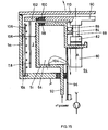
- the drive motor 80 Centrally to the axis A of the treatment chamber 3, which is also ring-shaped here, the drive motor 80 is provided for the carrier arrangement, which acts on the carrier plate 90 via a coupling 82, a shaft 88 mounted in bearings 84 and seals 86. Motor and plate drive are mounted within the inner wall ring 5i of the treatment room 3.
- the wall ring 5i as an HF electrode, is connected via a feedthrough 92 to an adaptation network and the high-frequency generator (not shown).
- the central space 94 of the arrangement, with the motor 80, the supply lines for this, etc., is shielded by means of a shield cylinder 96, which is at the same potential as the outer wall surface 5a acting as an electrode.
- the central, upper part of the core 64 of the recipient, which carries the inner wall ring 5i, is, as shown at 98, electrically connected to the reference potential by the outer part exposed to high frequency with the wall surface 5i and as a whole via the shield cylinder 96.
- a carrier ring 102 is supported on the periphery of the carrier plate 90, from the central part of which, as shown at 100, in an electrically insulated manner the carrier arrangement 7, 8 hangs or the carrier arrangement hangs.
- the outer wall with the outer wall ring 5a of the treatment room 3 carries lines of a gas distribution system 104 with, as shown, for example, upstanding gas ejection rods 106 for the admission of a reactive gas into the treatment room 3.
- reactive gas preferably on both sides of the carrier arrangement 7, 8, is admitted into the treatment annulus 3.
- Pump connections for pumping out the treatment room 3 are also preferably central, i.e. provided coaxially to the axis A, and the pumping out of the treatment room 3 is carried out through appropriately sized openings 104.
- the treatment room 3 is charged via a removable cover 110, as already described, or via one or two pivoting doors, as was explained with reference to FIGS. 7, 8.
- the most important thing about the last system configuration shown is the utilization of the central part surrounded by the inner wall ring 5i for pump connections and rotary drive of the carrier arrangement.
- a magnetic field is optionally generated axially in the treatment room 3, as is additionally the case with the coils 44 using FIG.
- the treatment room 3 or the inner and outer ring surfaces 5i, 5a are lined with removable sheets 108 which can be easily removed from the room 3 for cleaning.
- the diameter of the treatment room is more than 1 m
- the radial width of the treatment room is in the range of a few cm, for example of approximately 7 cm .
Description
Die vorliegende Erfindung betrifft eine Vakuumbehandlungsanlage gemäss Oberbegriff von Anspruch 1.The present invention relates to a vacuum treatment plant according to the preamble of
Für die Vakuumbehandlung von Werkstücken, darunter alle bekannten Behandlungsarten, wie PVD (physical vapor deposition), CVD (chemical vapor deposition) und alle Mischformen der genannten beiden Prinzipien, so beispielsweise plasmaunterstütztes CVD, reaktives Sputtern etc., ist es geläufig, Vakuumbehandlungskammern der Anlagen einzusetzen, welche innen ein in allen Richtungen zusammenhängendes, geschlossenes Volumen definieren, im Sinne eines dreidimensionalen, in allen drei Dimensionen zusammenhängenden Raumabschnitts.For the vacuum treatment of workpieces, including all known types of treatment, such as PVD (physical vapor deposition), CVD (chemical vapor deposition) and all mixed forms of the two principles mentioned, such as plasma-assisted CVD, reactive sputtering etc., it is common for vacuum treatment chambers of the systems to be used, which define a closed volume connected in all directions inside, in the sense of a three-dimensional space section connected in all three dimensions.
Aufgrund der in diesen bekannten Kammern lokal angeordneten Elektrodenanordnungen für Plasmaentladungsstrecken, Gaseinlässe, insbesondere für reaktive Prozesse, Trägeranordnungen für Werkstücke etc., ist es bei solcher Kammerauslegung und gegebenen Kammervolumen kaum möglich, sowohl die Erfordernis homogener Behandlungsverhältnisse über eine Vielzahl gleichzeitig zu behandelnder Werkstücke sicherzustellen und gleichzeitig das zur Verfügung stehende Kammervolumen für die höchstmögliche Zahl gleichzeitig zu behandelnder Werkstücke auszunützen. Es besteht in solchen Kammern, je nach Prozess mit unterschiedlichem Masse, ein sich durch das Kammervolumen erstreckender Behandlungsgradient, mit anderen Worten kann eine homogene, gleichförmige Behandlungswirkung, wie erwähnt, nur schwer über die an sich zur Verfügung stehenden Volumina aufrechterhalten werden.Because of the electrode arrangements for plasma discharge paths, gas inlets, in particular for reactive processes, carrier arrangements for workpieces, etc., which are arranged locally in these known chambers, it is hardly possible with such a chamber design and given chamber volume to ensure both the requirement of homogeneous treatment conditions over a large number of workpieces to be treated simultaneously and to use the available chamber volume for the highest possible number of workpieces to be treated at the same time. In such chambers, depending on the process with different dimensions, there is a treatment gradient that extends through the chamber volume, in other words, a homogeneous, uniform treatment effect, as mentioned, are difficult to maintain above the available volumes.
Aus der DE-OS 22 41 634, entsprechend der US-PS 3 856 654, ist eine Anlage mit einem Vakuumrezipienten für Werkstücke bekannt geworden, worin ein ringförmiger Behandlungsraum definiert ist. Die Werkstücke sind an einer zylinderförmigen Trägeranordnung im ringförmigen Behandlungsraum gelagert und werden bezüglich der Achse des Behandlungsraumes parallel und einzeln der Trägeranordnung im Behandlungsraum zugespiesen bzw. davon entfernt. Dies erfolgt durch die Wirkung eines Lade-/Entladeschiebers, der in einer fixen Drehposition der Trägeranordnung auf letztere eingreift.From DE-OS 22 41 634, corresponding to US Pat. No. 3,856,654, a system with a vacuum recipient for workpieces has become known, in which an annular treatment space is defined. The workpieces are mounted on a cylindrical support arrangement in the ring-shaped treatment room and are fed or removed from the support arrangement in the treatment room parallel and individually with respect to the axis of the treatment room. This takes place through the action of a loading / unloading slide which engages the latter in a fixed rotational position of the carrier arrangement.
Nachteilig an diesem Vorgehen, das auf dem Prinzip "first in, first out" beruht, ist, dass eine über die Zeit optimal homogene, ungestörte, gleichförmige Behandlungswirkung an den Werkstücken, mit welchen der Behandlungsraum chargiert ist, nur schwer realisierbar ist, und zwar aufgrund des Störeingriffes bei jeder Lade-/Entladeoperation.The disadvantage of this procedure, which is based on the "first in, first out" principle, is that an optimally homogeneous, undisturbed, uniform treatment effect over time on the workpieces with which the treatment room is charged is difficult to achieve, specifically due to the interference with every loading / unloading operation.
Es ist weiter aus der US-PS 3 892 198 bekannt, eine drehgetriebene Trägerkalotte für Werkstücke in einem zylindrischen Rezipienten einer Vakuumbehandlungsanlage dadurch zu beschicken, dass grossflächig ein Teil der Zylinderfläche des Rezipienten als Türe geöffnet werden kann.It is further known from US Pat. No. 3,892,198 to load a rotary driven spherical cap for workpieces in a cylindrical recipient of a vacuum treatment system in that part of the cylinder surface of the recipient can be opened as a door over a large area.
Dabei erfolgt die Werkstückbehandlung ab einer zentrischen Quelle.The workpiece treatment takes place from a central source.
Nachteilig an dieser Anlage ist, dass der Behandlungsraum schlecht ausgenützt ist und eine gleichförmige Behandlungswirkung der Werkstücke auf der Trägerkalotte trotz Drehbewegung nicht sichergestellt ist.A disadvantage of this system is that the treatment room is poorly used and a uniform treatment effect of the workpieces on the carrier cap is not ensured despite the rotary movement.
Es ist Aufgabe der vorliegenden Erfindung, ausgehend von einer Anlage letztgenannter Art, diesen Nachteil zu beheben.It is the object of the present invention, starting from a plant of the latter type, to remedy this disadvantage.
Dies wird an der Vakuumbehandlungsanlage eingangs genannter Art durch ihre Ausbildung nach dem Wortlaut des kennzeichnenden Teils von Anspruch 1 erreicht.This is achieved on the vacuum treatment plant of the type mentioned by its training according to the wording of the characterizing part of
Dadurch, dass der Behandlungsraum zwischen zwei koaxialen Flächen gebildet ist und dabei grossflächig geöffnet werden kann, um ihn gesamthaft zu chargieren bzw. zu entladen, ergibt sich die Möglichkeit, die einmal in den Behandlungsraum eingebrachten Werkstücke gleichzeitig so lange ungestört und insbesondere auch kontinuierlich frei von Beschleunigungsphasen zu bewegen und homogen gleichförmig zu behandeln, bis die angestrebte Behandlung abgeschlossen ist. Auch wenn an der erfindungsgemässen Anlage die im Behandlungsraum eingebrachten Werkstücke in Schritten bewegt werden, ergibt sich trotzdem die Möglichkeit, Beschleunigungs- und Abbremsphasen so auszulegen, dass die dadurch bewirkte Störung der Behandlung vernachlässigbar wird.The fact that the treatment room is formed between two coaxial surfaces and can be opened over a large area so that it can be charged or discharged in its entirety, makes it possible to simultaneously undisturbed the workpieces once they have been placed in the treatment room and, in particular, to continuously free them Move acceleration phases and treat them homogeneously and uniformly until the desired treatment is completed. Even if the workpieces introduced into the treatment room are moved in steps on the system according to the invention, there is nevertheless the possibility of designing acceleration and deceleration phases in such a way that the treatment disruption caused thereby becomes negligible.
Bei der Anlage gemass der US-PS 3 892 198 ist nämlich der Behandlungsraum nicht ringförmig ausgebildet, was erst - bei gegebener Anzahl gleichzeitig zu behandelnder Werkstücke - eine Minimalisierung des Behandlungsraumvolumens bei gleichzeitigem Erzielen einer gleichförmigen Behandlungswirkung entlang der ganzen Bewegungsbahn der Werkstücke durch den Behandlungsraum ermöglicht.In the system according to US Pat. No. 3,892,198, the treatment room is in fact not annular, which is only possible - given a number of workpieces to be treated simultaneously - to minimize the treatment room volume while at the same time achieving a uniform treatment effect along the entire movement path of the workpieces through the treatment room .
Indem nämlich erfindungsgemäss der Behandlungsraum zwischen zwei koaxialen Flächen gebildet ist, wird erreicht, dass er in seiner Abwicklung ausgesprochen lang wird und trotzdem optimal wenig Platz beansprucht.By forming the treatment space between two coaxial surfaces according to the invention, it is achieved that it becomes extremely long in its development and nevertheless optimally takes up little space.
Die Werkstücke "sehen" dann in jeder Drehposition gleiche Raumverhältnisse.The workpieces then "see" the same spatial conditions in every rotational position.
Im weiteren wird der Behandlungsraum zwischen den zylindrischen, koaxialen Flächen als "ringförmig" bezeichnet.In the following, the treatment space between the cylindrical, coaxial surfaces is referred to as "ring-shaped".
Auf dem erfindungsgemässen Konzept beruhend, wurden Anlagen realisiert, mit einem Aussendurchmesser des ringförmigen Behandlungsraumes von mehr als 1m und einer Ringraumbreite im Zentimeterbereich, wie beispielsweise mit einer Breite von ca. 7cm, Masse, die das oben Erläuterte klar manifestieren.Based on the concept according to the invention, systems were realized with an outer diameter of the ring-shaped treatment room of more than 1 m and a ring room width in the centimeter range, for example with a width of approx. 7 cm, which clearly manifest the above.
In einer bevorzugten Ausführungsvariante nach dem Wortlaut von Anspruch 2 weist der ringförmige Behandlungsraum an seiner Innen- und/oder Aussenfläche umlaufende Elektroden auf, womit, durch diese koaxiale Elektrodenanordnung entlang des Behandlungsraumes azimutal homogen eine Plasmaentladung im Behandlungsraum erzeugt wird, sei dies zwischen Innen- und Aussenfläche, zwischen Innenfläche und Werkstückträgern und/-oder zwischen Aussenfläche und Werkstückträgern.In a preferred embodiment variant according to the wording of
Bei einer weiteren bevorzugten Ausführungsvariante nach dem Wortlaut von Anspruch 3 wird die Innenwandung des ringförmigen Behandlungsraumes als Hochfrequenzelektrode eingesetzt, d.h. mit Hochfrequenzpotential beaufschlagt, womit die Aussenfläche auf ein Bezugspotential gelegt werden kann.In a further preferred embodiment variant according to the wording of
Der weiteren bevorzugten Ausführungsvariante nach Anspruch 4 folgend, wird der von der radial inneren Begrenzung des Behandlungsraumes umschlossene Raum für zusätzliche Anlageaggregate ausgenützt, wie für den Drehantrieb für die Trägeranordnung, Pumpen und Pumpanschluss, etc.Following the further preferred embodiment variant according to
Insbesondere bei kontinuierlich entlang des Behandlungsraumes umlaufender Elektrodenanordnung wird optimal homogene Behandlung bei Ausbildung der Anlage nach Anspruch 5 sichergestellt, d. h. durch Vorsehen eines kontinuierlichen Drehantriebes.Particularly in the case of an electrode arrangement which runs continuously along the treatment space, optimally homogeneous treatment is ensured when the system is constructed according to
Damit wird, beispielsweise und insbesondere bei einem plasmaunterstützten Vakuumprozess, insbesondere einem Plasmapolymerisationsprozess im Behandlungsraum, bei welchem ein oder zwei ringförmige Plasmaentladungsräume gebildet werden, je zwischen der einen Begrenzung des Behandlungsraumes und den Werkstückträgern, eine höchst gleichförmige Behandlung erzielt, beispielsweise wie erwähnt, bei einem plasmaunterstützten chemischen Beschichtungsprozess, bekannt unter dem Kürzel PECVD.In this way, for example and in particular in the case of a plasma-assisted vacuum process, in particular a plasma polymerization process in the treatment room, in which one or two annular plasma discharge spaces are formed, depending on the limitation of the treatment room and the workpiece carriers, a highly uniform treatment is achieved, for example as mentioned in one Plasma-assisted chemical coating process, known by the acronym PECVD.
Bei gegebener Achsialausdehnung des Behandlungsraumes wird das zur Verfügung gestellte Volumen bei Vorgehen nach dem Wortlaut von Anspruch 6 optimal genutzt, indem entlang einer Träger-Zylinderfläche eine Vielzahl gleichzeitig zu behandelnder Werkstücke gelagert wird, sei dies, um diese beidseitig gleich, beidseitig unterschiedlich oder auch nur einseitig zu behandeln. Dabei sei darauf hingewiesen, dass je nach elektrischem Betrieb und entsprechender Potentiallegung der Werkstückhalter in ein und demselben Behandlungsraum wahlweise unterschiedliche Behandlungsprozesse gefahren werden können, auch was die ein- oder zweiseitige Behandlung der Werkstücke anbelangt, was z.B. durch Auswechseln von mindestens Teilen der Trägeranordnung und/oder unterschiedliche Potentiallegung erfolgen kann.Given the axial extent of the treatment room, the volume made available is optimally used in the process according to the wording of claim 6, by storing a large number of workpieces to be treated simultaneously along a carrier cylinder surface, be it the same on both sides, different on both sides or even only treat unilaterally. It should be noted that depending on electrical operation and corresponding potential setting of the workpiece holder in the same treatment room, different treatment processes can optionally be carried out, also with regard to the one- or two-sided treatment of the workpieces, which can be done, for example, by exchanging at least parts of the carrier arrangement and / or different potential setting.
Um im weiteren das hinlänglich bekannte Problem der Vakuumprozesskontamination durch Abrieb bei im Prozessraum bewegten Werkstücken zu beheben, wird vorgeschlagen, die Anlage nach dem Wortlaut von Anspruch 10 auszubilden.In order to remedy the well-known problem of vacuum process contamination due to abrasion in workpieces moving in the process space, it is proposed to design the system according to the wording of claim 10.
Dadurch wird sichergestellt, dass Kontaminationspartikel generell und insbesondere Abriebpartikel, bedingt durch den Trägeranordnungsantrieb die Werkstückbehandlung nur in reduziertem Masse, wenn überhaut, beeinträchtigen können.This ensures that contamination particles in general and in particular abrasion particles, due to the carrier arrangement drive, can only impair the workpiece treatment to a reduced extent, if over skin.
Insbesondere, wenn entlang des Behandlungsraumes ein Bebandlungsprozess durchgeführt wird, wie beispielsweise für optische Bauelemente, woran höchste Anforderungen bezüglich Gleichförmigkeit erfüllt werden sollen, wird vorgeschlagen, die Anlage nach einem der Ansprüche 11 oder 12 auszubilden, d.h. die Trägeranordnung im Zentralbereich drehbeweglich zu lagern und vorzugsweise im Peripheriebereich anzutreiben, womit auch bezüglich Bewegungsführung höchstmögliche Gleichförmigkeit und aufgrund des bei Peripherieantriebes erzielten grossen Antriebsradius eine höchst präzise Bewegungsführung möglich wird.In particular, if a treatment process is carried out along the treatment room, for example for optical components, for which the highest requirements with regard to uniformity are to be met, it is proposed to design the system according to one of
Berücksichtigt man dabei die anzustrebenden relativ grossen Durchmesser des Behandlungsraumringes und die angestrebte Bewegungspräzision, mit welcher die Trägeranordnung im Behandlungsraum zu führen ist, mit exakt vorgegebenen konstanten, radialen Abstandsverhältnissen, und dass auch zu anderen Teilen des Behandlungsraumes genau vorgegebene Abstände bleibend eingehalten werden sollen, insbesondere auch die kleinen Dunkelraumabstände in der Grössenordnung einiger weniger Millimeter, so ist erkenntlich, dass der Drehlagerung der genannten Trägeranordnung grosse Bedeutung zukommt. Deshalb wird vorgeschlagen, nach dem Wortlaut des erwähnten Anspruchs 12 die Trägeranordnung, entweder im Zentralbereich oder im Peripheriebereich axial zu lagern und entsprechend im Peripheriebereich oder im Zentralbereich radial und dabei vorzugsweise den Antriebseingriff auf die Trägeranordnung im Zentralbereich oder im Peripheriebereich, vorzugsweise letzteres, vorzunehmen, dabei den genannten Antriebseingriff gleichzeitig als Teil der erwähnten Lagerung auszunützen.Taking into account the relatively large diameter of the treatment room ring to be aimed for and the desired precision of movement with which the carrier arrangement is to be guided in the treatment room, with exactly predetermined constant, radial spacing ratios, and that precisely specified distances to other parts of the treatment room should also be maintained, in particular Even the small darkroom distances on the order of a few millimeters, it can be seen that the pivot bearing of the support arrangement mentioned is of great importance. It is therefore proposed, according to the wording of claim 12 mentioned, to axially mount the carrier arrangement either in the central region or in the peripheral region and correspondingly radially in the peripheral region or in the central region and preferably to drive the carrier arrangement in the central region or in the peripheral region, preferably the latter, thereby exploiting the drive intervention mentioned at the same time as part of the storage mentioned.
Durch diese funktionsgetrennte Lagerung wird eine präzise Bewegungsführung ermöglicht, ohne dass konstruktiv höchst aufwendige Vorkehrungen getroffen werden müssten, die grossdurchmessrige Trägeranordnung in sich so auszubilden, dass sie im geforderten Umfange die genannten Anforderungen bleibend erfüllt.This function-separated storage enables precise movement control without having to take extremely complex structural measures to design the large-diameter carrier arrangement in such a way that it permanently fulfills the requirements mentioned in the required scope.
Um dabei sicherzustellen, dass z.B. thermisch bedingte Verformungen der Trägeranordnung zu Ungenauigkeiten in der Bewegungsführung der Werkstücke entlang des Behandlungsraumes führen, wird vorgeschlagen, dem Wortlaut von Anspruch 13 folgend, die Trägeranordnung mit einer Trägerplatte zu versehen, die durch Materialwahl und/oder Ausformungen, insbesondere axial elastisch deformierbar ist, vorzugsweise eine speichenartige Struktur aufweist und weiter vorzugsweise peripher axial gelagert ist.To ensure that, for example, thermal conditions Deformations of the carrier arrangement lead to inaccuracies in the movement of the workpieces along the treatment space, it is proposed, following the wording of
Durch eine solche Ausbildung der Trägeranordnung, beispielsweise mit elastisch quer zur Trägerebene, d.h. axial elastisch biegbaren Speichen, wird erreicht, dass, insbesondere bei zentraler Radiallagerung, sich die Trägerplatte aufgrund ihrer Elastizität optimal an die peripher vorgesehenen Axialführungen anlegen kann, so dass in diesem Bereich, woran auch zwischen die Wandungsringflächen einragende Partien der Trägeranordnung ansetzen, eine exakte Bewegungsführung gewährleistet ist und auch die oben erwähnten Abstände zu übrigen Teilen des Rezipienten während der Bewegung zeitkonstant eingehalten werden.Such a configuration of the carrier arrangement, for example with an elastic crosswise to the carrier plane, i.e. axially elastically bendable spokes, it is achieved that, in particular in the case of central radial bearings, the support plate can optimally lie against the axially provided axial guides due to its elasticity, so that in this area, where parts of the support arrangement projecting between the wall ring surfaces also begin, an exact movement control is guaranteed and the above-mentioned distances to other parts of the recipient are kept constant during the movement.
Damit wird das Einhalten von Dunkelraumabständen in der Grössenordnung von 3mm auch bei den grossen Durchmessern (≥ 1m) der Trägerplatte ohne grossen Aufwand möglich.This makes it possible to maintain darkroom distances of the order of 3mm even with the large diameters (≥ 1m) of the carrier plate without great effort.
In höchst einfacher Art und Weise wird weiter vorgeschlagen, dem Wortlaut von Anspruch 14 folgend, den Antrieb und insbesondere einen unten gelagerten Peripherieantrieb mittels eines Antriebrades auf die Trägeranordnung zu übertragen.In a very simple manner it is further proposed, following the wording of claim 14, the drive and in particular a peripheral drive mounted at the bottom by means of a drive wheel on the carrier arrangement transferred to.
Dadurch, dass, dem Wortlaut von Anspruch 15 bzw. 17 folgend, die Werkstückhalter - und mithin die darin gehalterten Werkstücke - bezüglich mindestens Teilen der Wandungsringflächen elektrisch isoliert sind, bevorzugterweise bezüglich Teilen beider Wandungsringflächen, wird höchste Flexibilität insofern erreicht, als dass die genannten Ringflächenteile und die Werkstücke je nach beabsichtigtem Behandlungsprozess unabhängig voneinander elektrisch betrieben werden können, je nach Beschaltung, so beispielsweise, dass die genannten Werkstückhalter potentialgleich mit Teilen an den Ringflächen des Behandlungsraumes oder dass Teile and beiden Ringflächen auf gegebenen elektrischen Potentialen betrieben werden, während die Werkstückhalter potentialschwebend betrieben werden, gemäss Anspruch 17 wie insbesondere für RF-Plasmaanwendungen, dabei insbesondere für Plasmapolymerisationsverfahren mit MF oder RF.Due to the fact that, according to the wording of
Dem Wortlaut von Anspruch 18 folgend, werden in bevorzugter Art und Weise mindestens Teile der Wandungsringflächen und mindestens Teile von Werkstückhaltern als Drei-Elektrodenanordnung elektrisch voneinander unabhängig betreibbar ausgebildet, sind also elektrisch voneinander isoliert montiert.Following the wording of claim 18, at least parts of the wall ring surfaces and at least parts of workpiece holders are preferably designed to be electrically operable independently of one another as a three-electrode arrangement, that is to say are mounted electrically insulated from one another.
In einer weiteren bevorzugten Ausführungsvariante, höchst geeignet insbesondere für die Beschichtung optischer Bauelemente, bei welchen höchste Anforderungen an die Gleichförmigkeit der Beschichtung und oft auch an die zweiseitige Beschichtung gestellt werden, wird vorgeschlagen, den erfindungsgemässen Vakuumrezipienten nach dem Wortlaut von Anspruch 16 auszubilden.In a further preferred embodiment variant, highly suitable in particular for the coating of optical components, in which the highest demands are placed on the uniformity of the coating and often are also placed on the two-sided coating, it is proposed to design the vacuum recipient according to the wording of claim 16.
Wird bezweckt, zwei ringförmige Plasmaentladungsräume zu schaffen, so zum Beispiel, um an optischen Bauelementen, wie an Linsen, deren eine den Wandungsringflächen je zugekehrte Oberflächen unterschiedlich zu beschichten, so werden mindestens Partien der Trägeranordnung, die zwischen die Wandungsringflächen einragen, metallisch ausgebildet und auf ein Bezugspotential gefesselt oder aber metallisch ausgebildet und potential beaufschlagt und dann die Elektroden an den Wandungsringen auf gleiche oder unterschiedliche Bezugspotentiale gelegt. Sollen die Werkstücke, wie beispielsweise bei RF-Plasmabehandlungen, potentialschwebend betrieben werden, so können die genannten Trägerpartien aus isolierendem Material gebildet sein, wobei in diesem Falle diese einragenden Partien, um keine Abschotung zwischen den Wandungsringfläche zu bilden, so ausgebildet sind, dass ein Entladungsdurchgriff von einer Wandungsringfläche zur anderen möglich ist. Die einragenden Trägerpartien werden dann z.B. gitterartig oder als einzelne einragende Trägerarme ausgebildet.If the aim is to create two annular plasma discharge spaces, for example in order to coat differently on optical components, such as lenses, one surface of which faces the wall ring surfaces, at least parts of the carrier arrangement which protrude between the wall ring surfaces are formed and made metallic a reference potential is tied up or is made of metal and is subjected to potential and then the electrodes are placed on the wall rings at the same or different reference potentials. If the workpieces are to be operated in a floating manner, for example in the case of RF plasma treatments, the carrier parts mentioned can be formed from insulating material, in which case these protruding parts are designed such that a discharge passage does not form a partition between the wall ring surfaces from one wall ring surface to another is possible. The protruding carrier sections are then e.g. designed like a lattice or as individual protruding support arms.
Es ist es weiter durchaus möglich, entlang des Behandlungsraumes nicht eine homogene, gleichförmige Behandlung vorzunehmen, sondern diskrete Behandlungsstationen vorzusehen, wie Zerstäubungs- und/oder Verdampfungsquellen und/oder Heiz- und/oder Aetz-Stationen.It is also entirely possible not to carry out a homogeneous, uniform treatment along the treatment room, but rather to provide discrete treatment stations, such as atomization and / or evaporation sources and / or heating and / or Aetz stations.
Durch Ausbildung des erfindungsgemässen Rezipienten nach dem Wortlaut von Anspruch 7 oder 8 wird erreicht, dass bestmögliche Zugänglichkeit in den Ringraum gegeben ist, was sich, wie ohne weiteres ersichtlich, höchst günstig auf die Beschickung, insbesondere eine automatische Beschickung, und die Innenraumreinigung auswirkt.By designing the recipient according to the invention according to the wording of
Die prinzipielle Auslegung des erfindungsgemässen Vakuumrezipienten ermöglicht, eine höchst kompakte Vakuumbehandlungsanlage aufzubauen.The basic design of the vacuum recipient according to the invention makes it possible to construct a highly compact vacuum treatment system.
Wie bereits erwähnt wurde, eignet sich der erfindungsgemässe Rezipient bzw. die erfindungsgemässe Vakuumbehandlungsanlage insbesondere für die gleichzeitige Behandlung optischer Bauteile auf zwei Seiten, dem Wortlaut von Anspruch 19 folgend, insbesondere für deren Beschichtung, insbesondere in einem reaktiven, plasmaunterstützten Behandlungsprozess, wobei, dem Wortlaut von Anspruch 20 folgend, sich insbesondere anbietet, den erwähnten erfindungsgemässen Rezipienten bzw. die damit ausgerüstete Vakuumbehandlungsanlage für die gleichzeitige, im wesentlichen gleiche, beidseitige Beschichtung optischer Bauteile einzusetzen, bei welchen, höchste Anforderungen an Gleichförmigkeit der Beschichtung, je einseitig betrachtet, aber oft auch über die zwei sich gegenüberliegenden Seiten betrachtet, wie bei Linsen, gestellt werden.As already mentioned, the recipient according to the invention or the vacuum treatment system according to the invention is particularly suitable for the simultaneous treatment of optical components on two sides, following the wording of
Die Erfindung wird anschliessend beispielsweise anhand von Figuren erläutert.The invention is subsequently explained, for example, using figures.
- Fig. 1Fig. 1
- schematisch, einen Rezipienten an einer Anlage gemäss vorliegender Erfindung,schematically, a recipient on a system according to the present invention,
- Fig. 2a, 2b2a, 2b
- an einem Rezipienten gemäss Fig. 1 zwei bevorzugte Werkstückträgeranordnungen, schematisch dargestellt,1, two preferred workpiece carrier arrangements, shown schematically on a recipient according to FIG.
- Fig. 3Fig. 3
- schematisch, die bevorzugte elektrische Beschaltung von Rezipientenringflächen und Werkstückträgern, mit der Darstellung möglicher Potentiallegungen dieser Teile,schematically, the preferred electrical circuitry of recipient ring surfaces and workpiece carriers, with the representation of possible potentials of these parts,
- Fig. 4a, 4b4a, 4b
- schematisch, Ausbildungsvarianten der Trägeranordnung gemäss Fig. 2a mit, weiterhin schematisch, der Positionierung von Werkstücken auf bzw. in der Trägeranordnung,schematically, training variants of the carrier arrangement according to FIG. 2a with, further schematically, the positioning of workpieces on or in the carrier arrangement,
- Fig. 5Fig. 5
- schematisch eine bevorzugte Ausbildung von Rezipient mit Trägeranordnung gemäss Fig. 1 bzw. Fig. 2a, b, zur Realisation unterschiedlicher Betriebsarten,schematically a preferred embodiment of recipient with carrier arrangement according to FIG. 1 or FIG. 2a, b, for realizing different operating modes,
- Fig. 6Fig. 6
- schematisch, eine erfindungsgemässe Anlage mit diskreten Behandlungsstationen,schematically, a system according to the invention with discrete treatment stations,
- Fig. 7Fig. 7
- schematisch eine weitere Ausführungsvariante des Rezipienten an einer erfindungsgemässen Anlage,schematically a further embodiment of the recipient on an inventive Investment,
- Fig. 8Fig. 8
- schematisch eine Aufsicht auf den Rezipienten von Fig. 7 in zwei unterschiedlichen Ausführungsvarianten, mit Zugangstüren und, als Teil einer Behandlungsanlage, mit Aggregaten bzw. Anschlüssen der Anlage,7 schematically shows a view of the recipient of FIG. 7 in two different design variants, with access doors and, as part of a treatment system, with units or connections of the system,
- Fig. 9a, 9b9a, 9b
- schematisch zwei bevorzugte Varianten der Lagerung eines Werkstückträgers am Rezipienten,schematically two preferred variants of the storage of a workpiece carrier on the recipient,
- Fig. 10Fig. 10
- schematisch eine bevorzugte Ausführungsvariante eines Antriebs tellers an einer Werkstückträgeranordnung am Rezipienten der erfindungsgemässen Anlage,schematically a preferred embodiment variant of a drive plate on a workpiece carrier arrangement on the recipient of the system according to the invention,
- Fig. 11Fig. 11
- eine Längsschnittdarstellung durch eine bevorzugte Realisationsform einer erfindungsgemässen Anlage,2 shows a longitudinal section through a preferred form of realization of a system according to the invention,
- Fig. 12Fig. 12
- eine schematische Längsschnittdarstellung durch eine weitere Ausführungsform einer erfindungsgemässen Anlage,2 shows a schematic longitudinal section through a further embodiment of a system according to the invention,
- Fig. 13Fig. 13
- eine schematische Längschnittdarstellung durch einen Teil einer weiteren Ausführungsform einer erfindungsgemässen Anlage,2 shows a schematic longitudinal section through part of a further embodiment of a system according to the invention,
- Fig. 14Fig. 14
- schematisch einen Längsschnitt durch einen Teil einer weiteren Ausführungsvariante einer erfindungsgemässen Anlage,schematically shows a longitudinal section through part of a further embodiment of a system according to the invention,
- Fig. 15Fig. 15
- schematisch einen Längsschnitt durch einen Teil einer heute bevorzugten Ausführungsvariante einer erfindungsgemässen Anlage.schematically shows a longitudinal section through part of a currently preferred embodiment variant of a system according to the invention.
In Fig. 1 ist schematisch der erfindungsgemässe Vakuumrezipient 1 dargestellt. Der Behandlungsraum 3 wird umspannt von einer äusseren Wandungsringfläche 5a und einer inneren 5i. Bevorzugterweise und aus noch zu beschreibenden Gründen ist der Vakuumrezipient 1 mit Wandungen 5a, 5i koaxial zu einer Achse A aufgebaut, welche bevorzugterweise und, wie dargestellt, vertikal steht.1 shows the
Insbesondere kann das von der inneren Wandungsringfläche 5i umspannte Volumen V für Aggregate einer Vakuumbehandlungsanlage mit dem erfindungsgemässen Vakuumrezipienten genutzt werden.In particular, the volume V spanned by the inner
In Fig. 2a, b sind wiederum schematisch zwei Ausschnitte aus dem erfindungsgemässen Vakuumrezipienten 1 dargestellt, mit zwei bevorzugten, prinzipiellen Trägeranordnungen für Werkstücke, die im Behandlungsraum 3 zu behandeln sind.2a, b, in turn, schematically show two sections from the
Die eine bevorzugte Trägeranordnung, gemäss Fig. 2a, umfasst einen Zylinder 7, welcher, in vorgegebenem Abstand, im Behandlungsraum 3 zwischen innerer und äusserer Wandungsringfläche 5i bzw. 5a angeordnet ist. Der Werkstückträgerzylinder 7 wird vorzugsweise im Behandlungsraum 3 in noch zu erläuternder Art und Weise getrieben, um die Achse A.One preferred carrier arrangement, according to FIG. 2a, comprises a
Gemäss Fig. 2b umfasst die zweite bevorzugte Trägeranordnung einen Trägerring 7a, woran Trägerarme 8 gelagert sind, welche gemeinsam ebenfalls eine Zylinderfläche aufspannen. An den Trägerarmen 8 sind Werkstücke 13, wie schematisch dargestellt, gehaltert. Auch der Trägerring 7a und damit die Trägerarme 8 und die Werkstücke 13 werden im Ringraum 3 um die Achse A der Ringkammer getrieben gedreht. Die Werkstücke 13 werden sowohl am oder im Trägerzylinder 7, wie auch an den Armen 8 mittels Werkstückhaltern 13a, wie beispielsweise mittels federnder Spangen, gehaltert.According to FIG. 2b, the second preferred carrier arrangement comprises a
In den erfindungsgemässen Rezipienten 1, insbesondere mit den bevorzugterweise vorgesehenen Trägeranordnungen 7 bzw. 7a, 8, können verschiedenartigste Vakuumbehandlungsverfahren an den Werkstücken 13 durchgeführt werden, wie erwähnt, PVD-Verfahren, CVD-Verfahren und alle Mischformen dieser beiden prinzipiellen Behandlungskategorien sowie Aetzverfahren, generell vakuumoberflächen-Behandlungsverfahren.In the
In Fig. 3 sind schematisch die drei Rezipiententeile, Innenwandungsringfläche 5i, Aussenwandungsringfläche 5a und dazwischen einragende Werkstückträgeranordnung 7 bzw. 7a, 8, rein schematisch dargestellt, wobei, wie mit der Isolation 9 veranschaulicht sei, diese drei Teile elektrisch voneinander isoliert sind. Dies ergibt, was, wie nun anhand der weiteren Ausführungen zu Fig. 3 deutlich werden wird, höchstmögliche Flexibilität bezüglich elektrischen Betriebs der drei Teile und damit bezüglich Verwendung des erfindungsgemässen Rezipienten für verschiedenartigste Vakuumbehandlungsverfahren. Jede der drei "Ringflächen", Aussenwandungsringfläche 5a, Innenwandungsringfläche 5i und Werkstückträger, können, prinzipiell als Drei-Elektrodenanordnung, wahlweise elektrisch beschaltet werden. Dies ist in Fig. 3 mit "Möglichkeitswählern" 11 anschaulich gemacht, die weniger als Umschalteinheiten zu verstehen sind als als graphische Darstellung der verschiedenen Möglichkeiten, die genannten Teile relativ zueinander elektrisch zu betreiben.In Fig. 3 the three recipient parts, inner
Wie ersichtlich, kann die Innenwandungsringfläche 5i mit DC- oder AC-Energie gespiesen werden, bis hin in den RF-Bereich oder gar, bei dem Fachmann bekannter, entsprechender Auslegung, in den Mikrowellenbereich. Gleichzeitig kann die Trägeranordnung 7 bzw. 7a, 8 potentialschwebend geschaltet sein und die Aussenwandungsringfläche 5a auf Bezugspotential oder aber die Trägeranordnung 7 bzw. 7a, 8 gemeinsam mit Aussenwandungsringfläche 5a auf Bezugspotential gelegt sein. Es kann dabei auch die Trägeranordnung 7 bzw. 7a, 8 auf Bezugspotential und gleichzeitig die Aussenwandungsringfläche 5a auf DC- oder AC-Potential gelegt werden, wiederum gegebenenfalls bis hin in den Mikrowellenbereich. Im letzterwähnten Fall werden zwei Diodenentladungsräume geschaffen, je zwischen einer der Wandungsringflächen und der Trägeranordnung, die gleich oder unterschiedlich betreibbar sind. Bei schwebend betriebener Trägeranordnung oder auf Bias gelegter liegt er innerhalb des einen zwischen den Wandungsringflächen 5a bzw. 5i gebildeten Entladungsraumes. Von den erwähnten Möglichkeiten ausgehend, erkennt nun der Fachmann ohne weiteres die möglichen Kombinationen, wie die erwähnten Teile, je nach Einsatzzweck des erfindungsgemässen Rezipienten, flexibel elektrisch beschaltet werden können.As can be seen, the inner
In den Fig. 4a und 4b sind, schematisch, unterschiedliche Ausbildungsformen des Werkstückträgerzylinders 7 gemäss Fig. 2a dargestellt, als eine der bevorzugten Varianten der Trägeranordnung 7, 7a, 8.4a and 4b show, schematically, different configurations of the
Gemäss Fig. 4a besteht er im wesentlichen aus isolierendem Material für den Betrieb des Behandlungsraumes 3 gemäss Fig. 3 als ein Entladungsstreckenraum. Wie in Fig. 4a unten schematisch dargestellt, sind Werkstücke 13, beispielsweise optische Linsen aus einem Kunststoff, von beiden Seiten zugänglich mittels Haltespangen 13a im Kunststoffträgerzylinder 7 gelagert, wobei, wie aus Fig. 4a ersichtlich, massgebliche Partien 15 des Zylinders 7 ausgenommen sind, um den Durchgriff der zwischen den Wandungsringen 5i und 5a aufgebauten Entladung zu ermöglichen, was bei Aufbau der Anordnung 7a, 8 gemäss Fig. 2b ohnehin gegeben ist. Gemäss Fig. 4b bestehen mindestens wesentliche Partien des Trägerzylinders 7 aus elektrisch leitendem Material. Damit ist die Möglichkeit geschaffen, diesen Zylinder bzw. die daran oder darauf gehalterten Werkstücke 13 auf beliebiges Potential zu legen und damit den Behandlungsraum 3 als Zweikammernraum zu betreiben oder als Einkammernraum zwischen den Ringen 5i und 5a und auf Bias-gelegten Werkstücken 13 oder gegebenenfalls auch als Einkammernraum zwischen einem der Ringe 5i oder 5a und auf Bezugspotential gelegten Werkstückträgerzylinder 7 für die einseitige Behandlung von Werkstücken. Bezüglich Werkstoffwahl (isolierend, leitend) und elektrischer Betriebsmöglichkeiten gilt für die zweite bevorzugte Ausbildung der Trägeranordnung nach Fig. 2b Entsprechendes.According to FIG. 4a, it essentially consists of insulating material for the operation of the
Wie in Fig. 4b unten dargestellt, ergibt sich bei leitendem Zylinder 7 die Möglichkeit, die Werkstücke 13 beidseitig zugänglich und behandelbar im Trägerzylinder 7 anzuordnen, dabei die beidseitige Beschichtung in zwei getrennt betriebenen Behandlungsteilräumen gemäss Fig. 3, 3i und 3a zu behandeln oder, bei potentialschwebend-geschaltetem Trägerzylinder 7, eine zweiseitige Behandlung der Werkstücke 13 in einem einheitlichen Behandlungsraum 3 gemäss Fig. 3 vorzunehmen. Ebenfalls ist die Möglichkeit geschaffen, Werkstücke 13 auf den Trägerzylinder 7 aufzulegen und je in den Behandlungsräumen 3i und 3a gemäss Fig. 3 die doppelte Anzahl Werkstücke gleichzeitig und einseitig zu behandeln. Auch dies kann bei der Anordnung von Trägerarmen 8 gemäss Fig. 2b realisiert werden, indem die stabilen Halterungen 13a auch ein- oder zweiseitige Zugänglichkeit der Werkstückoberflächen gewährleisten können.As shown in FIG. 4b below, there is the possibility in the case of a
Wie sich dem Fachmann nun ohne weiteres ergibt, sind im Rahmen des fachmännischen Könnens praktisch keine Grenzen gesetzt, bekannte Behandlungsverfahren, bei entsprechender elektrischer Beschaltung und entsprechender Auslegung der Trägeranordnung 7 bzw. 7a, 8 mit dem erfindungsgemässen Rezipienten auszuführen. Er lässt sich frei wählbar als Doppeldioden-, Einfachdioden- oder Triodenanordnung betreiben, als Doppeldiodenanordnung, insbesondere für zweiseitige, gleiche oder unterschiedliche Plasmapolymerisation.As is readily apparent to the person skilled in the art, there are practically no limits within the scope of the skill in the art, known treatment methods for to carry out corresponding electrical wiring and appropriate design of the
Im weiteren kann die Trägeranordnung mit anderen Behandlungsquellen als Bias-Anordnung für die Werkstücke betrieben werden.Furthermore, the carrier arrangement can be operated with other treatment sources as a bias arrangement for the workpieces.
In Fig. 5 ist, wiederum schematisch, eine bevorzugte Ausführungsform dargestellt, bei welcher mindestens wesentliche Partien von Aussen- und Innenwandungsringflächen 5a bzw. 5i und der Trägeranordnung 7 bzw. 7a, 8 umlaufend gleichförmig als Elektrodenanordnungen in der erwähnten Dioden- oder Trioden-Beschaltungen wirken. Links ist, schematisch, der Entladungsraum ET bei Triodenbeschaltung dargestellt, rechts die beiden Entladungsräume ED1, ED2 bei Doppeldiodenbeschaltung.5, again schematically, shows a preferred embodiment in which at least essential parts of the outer and inner wall ring surfaces 5a and 5i and the
Wie bereits eingangs erwähnt wurde, wird zur Erzielung höchster Behandlungshomogenität, wie mit dem Pfeil F in Fig. 5 dargestellt, die Trägeranordnung 7 bzw. 7a, 8 zwischen den Wandungsringflächen drehbewegt. Dies ergibt nun gemäss Fig. 6 auch die Möglichkeit, an der Innen- oder Aussenwandungsringfläche, hier schematisch an der Aussenwandungsringfläche 5a dargestellt, diskrete Behandlungsstationen 17 zu montieren, wie Sputter-Quellen, Heizquellen, Aetzquellen, Bogenverdampfungsquellen, Elektrodenstrahl-Verdampfungsquellen etc. Wird bei Ausbildung des erfindungsgemässen Rezipienten prinzipiell gemäss Fig. 5 die Werkstückträgeranordnung, zur Erlangung höchstmöglicher Behandlungsgleichförmigkeit, kontinuierlich angetrieben, so wird es bei Ausbildung nach Fig. 6 vorzugsweise intermittierend, d.h. in Schritten betrieben, so dass die auf bzw. an der Werkstückträgeranordnung 7 bzw. 7a, 8 gehalterten Werkstücke sequentiell von Behandlungsstation zu Behandlungsstation gefördert werden.As already mentioned at the beginning, the
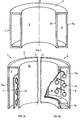
In den Fig. 7 und 8 ist ein wesentlicher Aspekt des erfindungsgemässen Rezipienten dargestellt, nämlich den ringförmigen Behandlungsraum grossflächig öffnen zu können, um ihn mit der Mehrzahl Werkstücke 13 zu chargieren bzw. zu dechargieren. Demnach umfasst in einer ersten bevorzugten Ausführungsvariante die Aussenwandungsringfläche 5a mindestens eine Türschale 19, welche parallel zur Ringachse A an Schwenklagern 21 schwenkgelagert ist, wie dargestellt vorzugsweise zwei derartige Türschalen 19. Damit wird ermöglicht, dass der Behandlungsraum 3 in optimaler Art und Weise zugänglich wird, sei dies, um den vorgesehenen Werkstückträger zu beschicken oder zu entladen oder um den Behandlungsraum zu reinigen.7 and 8 illustrate an essential aspect of the recipient according to the invention, namely to be able to open the annular treatment space over a large area in order to charge or decharge it with the plurality of
Wie in Aufsicht aus Fig. 8 ersichtlich, können die vorzugsweise zwei vorgesehenen Türschalen 19, wie dies bei 19a dargestellt ist, ausschliesslich als Schalen der äusseren Ringfläche 5a ausgebildet sein oder, wie rechts mit 19 bezeichnet, mindestens teilweise wannenartig, einen Bodenteil 19c des Rezipienten mitumfassen. Zwischen den beiden, wie auch immer ausgebildeten Türschalen 19 bzw. 19a bleibt ein relativ schmaler Mittensteg der äusseren Ringfläche 5a stationär, woran, wie aus Fig. 8 ersichtlich, Aggregate der Anlage, so beispielsweise ein Pumpanschluss 22 für den Innenraum oder Gasanschlüsse 24 für Arbeits- oder Reaktivgas, montiert sind.As can be seen in the top view from FIG. 8, the preferably two provided
In Fig. 9a ist schematisch eine erste bevorzugte Ausführungsvariante der Drehlagerung der Werkstückträgeranordnung dargestellt. Die Trägeranordnung umfasst einen Trägerteller 25, woran der vorbeschriebene Zylinder, sei dies durch einen Trägerzylinder 7 selbst gemäss Fig. 2a oder diskrete Trägerarme 8 gemäss Fig. 2b aufgespannt, peripher, gegebenenfalls auswechselbar gelagert ist. Der Trägerteller 25 ist gemäss Fig. 9a in seinem Zentralbereich um die Innenraumachse A radial gelagert und in seinem Peripheriebereich axial abgestützt bzw. gelagert, wobei bevorzugterweise die periphere Axiallagerung mindestens zum Teil durch einen Antriebseingriff auf den Teller 25 gebildet ist, wozu die axiale Abstützung 27 ein Antriebsrad (nicht dargestellt) umfasst.9a schematically shows a first preferred embodiment variant of the rotary mounting of the workpiece carrier arrangement. The carrier arrangement comprises a
In Fig. 9b sind die Funktionen von Zentral- und Peripherlagerung bezüglich Fig. 9a vertauscht, indem hier der Trägerteller 25 in seinem Zentralbereich axial abgestützt ist und peripher radial gelagert ist. Durch die in den Fig. 9 dargestellte bevorzugte Trennung von Radiallagerung und Axiallagerung wird erreicht, dass die in vielen Fällen grossdurchmessrige Trägerscheibe 25, statisch bestimmt, höchst exakt bewegt wird, ohne dass sich, beispielsweise bei Tellerdurchmessern ≥ 1m, z.B. temperaturbedingte Tellerverzüge auf die exakte Bewegungsführung der Trägeranordnungspartien entsprechend 7, 7a oder 8 auswirken würden. Auf diese Art und Weise werden aufwendige konstruktive Vorkehrungen am Trägerteller 25 selbst, zur Sicherstellung der genannten Präzision auch unter Betriebsverhältnissen, umgangen.In FIG. 9b, the functions of central and peripheral storage with respect to FIG. 9a are interchanged in that here the
In Fig. 10 ist schematisch in Aufsicht der erwähnte Trägerteller 25 dargestellt. Zur Behebung allfälliger Verzüge, wie unter Betriebstemperaturen, wird der Teller 25 vorzugsweise weiter so ausgebildet, dass er in Axialrichtung A elastisch verformbar ist. Damit wird in seinem Peripheriebereich, beispielsweise betrachtet im Zusammenhang mit Fig. 9a, erreicht, dass er durch sein Eigengewicht und dasjenige der aufragenden Werkstückträgeranordnungsteile 7 etc. permanent bündig auf das Axiallager 27 bzw. die dieses Lager bildenden Organe gedrückt wird. Hierzu umfasst der Trägerteller 25 bevorzugterweise eine speichenartige Struktur mit Speichen 25a, welche, gepaart mit entsprechender Wahl eines elastischen Materials, mindestens für Teile des Tellers, und/oder deren entsprechende Dickendimensionierung, die obgenannte Auflage sichergestellt wird, wobei gleichzeitig auch kleine Dunkelraumabstände von z.B. 3mm zwischen Tellerfläche und benachbarten, stationären Rezipiententeilen eingehalten werden, indem ein mechanisches Wobbeln des Tellers vermieden wird.In Fig. 10, the
In Fig. 11 ist schematisch eine bevorzugte Ausführungsvariante des erfindungsgemässen Rezipienten dargestellt. Es sind den bis anhin prinzipiell erläuterten Teilen dieselben Positionsziffern zugeordnet. Der ringförmige Behandlungsraum 3, unterteilt in die Behandlungsräume 3i und 3a, ist radial begrenzt durch die Innenwandungsringfläche 5i und die Aussenwandungsringfläche 5a. Die Ringflächen 5i und 5a werden durch je eine koaxiale Kammer 27i bzw. 27a gebildet, wobei die innere Kammer 27i über eine elektrische Isolation 29 von der äusseren 27a getrennt ist. Während obere Abschlussplatten 28i bzw. 28a der beiden Kammern auf Dunkelraumabstand gehalten sind, liegt zwischen den unteren Abschlussplatten 29i und 29a der genannten Kammer die Trägerplatte 25. Sie ist zentral durch Radiallager 33 drehgelagert und weist zu den benachbarten unteren Abschlussplatten 29i bzw. 29a je Dunkelraumabstand auf. An ihrer Peripherie trägt sie gemäss Fig. 2a oder 2b ausgebildete Werkstückträgeranordnungen 7 bzw. 7a, 8, bevorzugterweise auswechselbar, und ruht auf Axiallagern, dabei insbesondere auf einem Antriebsrad 37, welches durch einen Motor M und über eine dynamische Vakuumdichtung 39 angetrieben wird und das, wie schematisch bei 41 dargestellt ist, bezüglich Motor und Ringfläche 5a elektrisch isoliert ist oder selbst aus isolierendem Material besteht. Selbstverständlich sind vorzugsweise entlang der Peripherie des Trägerrades 25 weitere axiale Abstützflächen vorgesehen, wie beispielsweise Laufrollen. Der Trägerteller 25 wird bevorzugterweise ausgebildet, wie anhand von Fig. 10 erläutert wurde. Mit dem Motor M wird die gesamte Werkstückträgeranordnung kontinuierlich, oder falls diskrete Behandlungsstationen gemäss Fig. 6 vorgesehen sind, in Schritten getrieben.A preferred embodiment variant of the recipient according to the invention is shown schematically in FIG. The same item numbers are assigned to the parts that have been explained in principle up to now. The
Wie anhand von Fig. 7 bzw. 8 dargestellt wurde, umfasst der bevorzugte Rezipient, hier nicht dargestellt, zwei Türschalen an der äusseren Wandungsringfläche 5a. Soll das zentrale Volumen V für Anlageaggregate genutzt werden, so werden die oberen Abschlussplatten 28a bzw. 28i weggelassen, und an deren Statt werden die oberen Abschlüsse der Wandungsringflächen 5i bzw. 5a isoliert und vakuumdicht verbunden.7 and 8, the preferred recipient, not shown here, comprises two door shells on the outer
Im weiteren werden bevorzugterweise Helmholzspulen 44 vorgesehen, um im Behandlungsraum 3 ein im wesentlichen zur Achse A paralleles Magnetfeld B zu erzeugen, sofern ein solches Magnetfeld beim mit dem Rezipienten durchgeführten Behandlungsprozess erfordert ist. Das resultierende Magnetfeld B ist auch in den Fig. 7 und 8 in einer der möglichen Polaritäten eingetragen.In addition, helmwood coils 44 are preferably provided in order to generate a magnetic field B essentially parallel to the axis A in the
Es muss betont werden, dass der Werkstückträgerzylinder 7 bzw. Werkstückträger-Armstrukturen nicht zwingend, wie dargestellt, symmetrisch zwischen Innen- und Aussenwandungsringflächen angeordnet werden muss, sondern je nach beabsichtigter Behandlung auch näher an der einen der beiden Wandungsringflächen liegen kann. Durch die hohe Bewegungspräzision, insbesondere der Peripherie des Trägertellers 25, unter Einhaltung der Dunkelraumabstände zu den unteren Abschlussplatten 29a bzw. 29i, ergibt sich, dass mit entsprechend hoher Präzision die Werkstücke in gegebenem Abstand von den Ringflächen bewegt werden, die als Elektrodenflächen, je nach dem beabsichtigten Behandlungsverfahren, elektrisch betrieben werden, gemäss Fig. 3. In Fig. 11 nicht eingetragen sind die elektrischen Beschaltungen, insbesondere der Ringflächen 5i bzw. 5a und des Werkstückträgers 7 bzw. 7a, 8, die jedoch alle drei voneinander isoliert sind, so dass eine der vorerläuterten Beschaltungsart vorgenommen werden kann.It must be emphasized that the
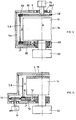
In den Fig. 12 bis 15 sind schematisch weitere Ausführungsvarianten der erfindungsgemässen Behandlungsanlage dargestellt, wobei Fig. 15, wie erwähnt, schematisch, eine der heute bevorzugten Konfigurationen darstellt.12 to 15 schematically show further design variants of the treatment plant according to the invention, with FIG. 15, as mentioned, schematically representing one of the configurations preferred today.
Gemäss Fig. 12 bildet die innere Wandungsringfläche 5i die über ein Anpassnetzwerk an einen Hochfrequenzgenerator, in der Einheit 50 dargestellt, angeschlossene HF-Elektrode. Die äussere Wandungsringfläche 5a bildet die hier beispielsweise auf Massepotential gelegte Gegenelektrode. Die die Hochfrequenzelektrode bildende Wandungsringfläche 5i ist, wie bei 52 dargestellt, von der mit der äusseren Wandungsringfläche 5a auf gleichem Potential betriebenen Bodenfläche 54 des Rezipienten elektrisch isoliert. Mittels eines Motors 54, der bezüglich der Rezipientenaussenwandung mit dem Wandungsaussenring 5a an einem Montageflansch 56 ortsfest montiert ist, wird der Trägerteller 58 vorzugsweise kontinuierlich drehgetrieben. Der Trägerteller 58 ist vorzugsweise aus dielektrischem Material gefertigt.According to FIG. 12, the inner
Am Trägerteller 58 ist ein äusserer Ring 60 entfernbar eingelegt, woran die vorbeschriebenen Träger 7 bzw. 8 hängen. Zur Chargierung des Behandlungsringraumes 3 werden Deckel 59, wie mit den Pfeilen schematisch dargestellt, abgehoben, welche bezüglich des Montageflansches 56 mit Dichtungen 62 in geschlossenem Zustand abgedichtet sind, und es wird der äussere Ring 60 mit der Charge auf den Teller 58 aufgelegt.An
Wie ersichtlich, erlaubt auch diese Konfiguration einen Behandlungsraum 3 mit optimal wenig Toträumen zu schaffen, was betreffs Reinhaltung des Behandlungsraumes wesentlich ist. Der Behandlungsraum 3 ist weiter einfach zugänglich und es ist lediglich eine Wellendichtung für die Motorwelle am Montageflansch 56 notwendig. Wiewohl gemäss der Darstellung von Fig. 12 die Werkstücke auf Schwebepotential im Behandlungsraum 3 gehaltert sind, ist es durchaus möglich, an die Werkstücke, gezielt, ein Bias-Potential zu legen.As can be seen, this configuration also allows a
Gemäss Fig. 13 bildet der innere Wandungsring 5i des Behandlungsraumes 3 wiederum die HF-Elektrode. Der äussere Wandungsring 5a ist oben wiederum durch entfernbare Deckel 58 abgeschlossen. Der im Montageflansch 56 gehalterte Motor 54 wirkt auf den Trägerteller 58 aus vorzugsweise dielektrischem Material, an welchem, peripher, der Ring 60 azimutal in Eingriff steht. Axial, d.h. in Richtung der Behandlungsraumachse A, stützen sich hier die Träger 7, 8 auf einer unteren Trägerplatte 66 ab, welche, achsial fest, an Lagern, beispielsweise Kugellagern 68 bezüglich der HF-Durchführung zur HF-Elektrode, entsprechend dem inneren Wandungsring 5i, drehbeweglich gelagert ist. Auch hier sind die sich unmittelbar in der Nähe der mit HF-beaufschlagten Flächen des durch die innere Wandungsfläche 5i bildenden Kerns 64 des Rezipienten gebogenen Flächen der drehgetriebenen Trägeranordnung, vorzugsweise aus dielektrischem Material gefertigt. Der Antrieb über Motor 54 erfolgt über den Teller 58 azimutal auf den Ring 60, überträgt sich über die Träger 7, 8 auf den unteren Teller 66, worauf sich die Träger axial abstützen. Auch hier kann zum Chargieren der Anlage nach Entfernen der Deckel 59 die Substratträgeranordnung bereits chargiert, als Ganzes in den Behandlungsraum 3 eingebracht bzw. daraus entfernt werden.13, the
Bei der Ausführungsvariante nach Fig. 14 bildet die innere Wandungsfläche 5i wiederum HF-Elektrode und ist hierzu mit dem Anpassungsnetzwerk und dem HF-Generator in der Einheit 50 verbunden. Auf einem unteren Trägerteller 70, drehbeweglich an Lagern 72 und axial fest gelagert, stehen die Trägeranordnungen bzw. steht die Trägeranordnung 7, 8, wie schematisch dargestellt, auf einem Sockelring 74. Der Teller 70 wird durch den Antriebsmotor 74 und Reibrad 76 getrieben. Der Behandlungsraum 3 wird von einem, wie mit dem Pfeil angedeutet, entfernbaren Deckel 78 abgeschlossen, nach dessen Oeffnen die Trägeranordnung 7, 8 mit dem Ring 74, vorzugsweise als Ganzes, aus dem Behandlungsraum 3 entfernt werden kann.In the embodiment variant according to FIG. 14, the
In Fig. 15 ist eine heute bevorzugte Ausführungsvariante der Anlage für Hochfrequenz-Plasmabehandlung dargestellt. Zentrisch zur Achse A des auch hier ringförmigen Behandlungsraumes 3 ist der Antriebsmotor 80 für die Trägeranordnung vorgesehen, welche über eine Kupplung 82, eine in Lagern 84 und Dichtungen 86 gelagerte Welle 88 auf den Trägerteller 90 wirkt. Motor und Tellerantrieb sind innerhalb des inneren Wandungsringes 5i des Behandlungsraumes 3 montiert. Der Wandungsring 5i ist, als HF-Elektrode, über eine Durchführung 92 mit einem Anpassungsnetzwerk und dem Hochfrequenzgenerator (nicht dargestellt) verbunden.15 shows a preferred embodiment variant of the system for high-frequency plasma treatment. Centrally to the axis A of the
Der Zentralraum 94 der Anordnung, mit dem Motor 80, den Zuleitungen hierzu etc. ist mittels eines Schirmzylinders 96 abgeschirmt, der auf dasselbe Potential gelegt ist, wie die als Elektrode wirkende Aussenwandungsfläche 5a. Der zentrale, obere Teil des den Wandungsinnenring 5i mittragenden Kernes 64 des Rezipienten ist, wie bei 98 dargestellt, elektrisch vom hochfrequenzbeaufschlagten äusseren Teil mit der Wandungsfläche 5i und als Ganzes über den Schirmzylinder 96 auf Bezugspotential gelegt.The
An der Peripherie des Trägertellers 90 stützt sich, von dessen Zentralteil, wie bei 100 dargestellt, elektrisch isoliert, ein Trägerring 102 ab, woran die Trägeranordnung 7, 8 hängt bzw, die Trägerranordnungen hängen. Die äussere Wandung mit dem äusseren Wandungsring 5a des Behandlungsraumes 3 trägt Leitungen eines Gasverteilsystems 104 mit, wie beispielsweise dargestellt, aufragenden Gasausdüsstäben 106 für den Einlass eines Reaktivgases in den Behandlungsraum 3. Insbesondere für die zweiseitige und gleichzeitige Beschichtung von Werkstücken, wie insbesondere durch Plasmapolymerisation, wird Reaktivgas, vorzugsweise beidseitig der Trägeranordnung 7, 8, in den Behandlungsringraum 3 eingelassen.A
Auch Pumpanschlüsse zum Abpumpen des Behandlungsraumes 3 werden vorzugsweise zentral, d.h. koaxial zur Achse A vorgesehen, und das Abpumpen des Behandlungsraumes 3 durch entsprechend bemessene Oeffnungen 104 vorgenommen. Die Chargierung des Behandlungsraumes 3 erfolgt über einen entfernbaren Deckel 110, wie bereits beschrieben oder über eine oder zwei Schwenktüren, wie anhand von Fig. 7, 8 erläutert wurde. Wesentlich an der zuletzt gezeigten Anlagenkonfiguration ist u.a. die Ausnützung des vom inneren Wandungsring 5i umgebenen Zentralteils für Pumpanschlüsse und Drehantrieb der Trägeranordnung. Bei allen vorgestellten Konfigurationen wird, wie dem Fachmann bekannt, gegebenenfalls ein Magnetfeld axial im Behandlungsraum 3 erzeugt, wie anhand von Fig. 11 mit den Spulen 44 zusätzlich gegebenenfalls mittels entsprechend angeordneter Polschuhe und/oder Permanentmagnete.Pump connections for pumping out the
Im weiteren ist selbstverständlich, dass, wie in Fig. 15 gestrichelt dargestellt, der Behandlungsraum 3 bzw. Innen- und Aussenringflächen 5i, 5a mit entfernbaren Blechen 108 verkleidet werden, die zur Reinigung leicht aus dem Raum 3 entfernbar sind. Bei der heute realisierten Anlage, im wesentlichen nach Fig. 15, zusätzlich mit Spulen 44 nach Fig. 11 versehen, beträgt der Durchmesser des Behandlungsraumes mehr als 1m, die radiale Breite des Behandlungsraumes liegt im Bereich einiger weniger cm, so z.B. von ca. 7cm.Furthermore, it goes without saying that, as in 15 shown in broken lines, the
Claims (21)
- Vacuum treatment apparatus for workpieces comprising a on the outside annular treatment chamber (3) and rotatable carrier means (7,7a,8) for a multitude of workpieces (13) in the treatment chamber (3), which are linked with rotating drive means, and wherein one substantial part of the wall of said treatment chamber may be opened for charging and discharging the treatment chamber (3) with said workpieces (13), characterised in that said treatment chamber (3) is delimited by two substantially cylindrically and mutual coaxial wall portions (5a, 5i) and the carrier means (7,7a,8) are projecting in between said wall surfaces.
- Apparatus according to claim 1, characterised in that the treatment chamber (3) comprises along its radial inner and/or outer wall surface an annular surrounding electrode surface for the generation of a plasma discharge in said treatment chamber (3).
- Apparatus according to claim 1 or 2, characterised in that the coaxial inner wall (5i) of the treatment chamber (3) is connected to an rf-generator (50) for generating a rf-plasma discharge.
- Apparatus according to any of claims 1 to 3, characterised in that radially inside said inner wall surface (5i), there are provided additional systems, especially rotating drive means (80) for the carrier means and/or a pumping connector.
- Apparatus according to any of claims 1 to 4, characterised in that the carrier means are linked with a continous rotating drive means.
- Apparatus according to any of claims 1 to 5, characterised in that the carrier means (7,7a,8) defines a cylindrical surface, having a plurality of workpiece holders (13a) beeing distributed along said surface.
- Apparatus according to any of claims 1 to 6, characterised in that a substantial part of the radial outer wall surface (5a) may be opened for charging and discharging the treatment chamber.
- Apparatus according to any of claims 1 to 7, characterised in that at least one front terminal portion (4) of the treatment chamber (3) may be opened for charching and discharging the treatment chamber (3).
- Apparatus according to any of claims 1 to 8, characterised in that the carrier means are defining a cylinder wall for one or several workpieces (13) by discrete carrier rods (8), being disposed substantially parallel to the axis (A) of the coaxial surface walls, or by a carrier cylinder (7).
- Apparatus according to any of claims 1 to 9, characterised in that the treatment chamber (3) is substantially arranged with vertical axis (A), and comprising bearing means for rotatably bearing said carrier (7,7a,8) which are beeing disposed at the bottom of said treatment chamber (3), and preferably a drive means acts on said carrier means at the bottom of said treatment chamber.
- Apparatus according to any of claims 1 to 10, characterised in that the carrier means (7,7a,8) comprising centraly rotatable bearing means and are preferably driven at the periphery.
- Apparatus according to any of claims 1 to 11, characterised in that the carrier means comprising centraly radialy and peripheral axial bearing means or vice versa, and that the driving means acts preferably central or peripheral on the carrier means and then preferably forms at least part of one of said bearing means.
- Apparatus according to any of claims 1 to 12, characterised in that the carrier means comprising a rotatable carrier plate (25), being formed so as to be elastically deformable by choosing the material and/or its structure, preferably comprising a spoked structure which is preferably supported peripheraly in the direction of the axis (A) of the treatment chamber.
- Apparatus according to any of claims 1 to 13, characterised in that a driving motor for the carrier means act via a driving wheel (37) on the carrier means.
- Apparatus according to any of claims 1 to 14, characterised in that workpiece holders mounted on the carrier means are electrically isolated arranged from other parts of the apparatus and are selectively set to an electrical potential.
- Apparatus according to any of claims 1 to 15, characterised in that workpiece holders (13a) are beeing moved along said carrier means at substantially equal distance between the wall surfaces (3).
- Apparatus according to any of claims 1 to 16, characterised in that workpiece holders (13a) on the carrier means beeing at floating eletrical potential.
- Apparatus according to any of claims 1 to 17, characterised in that at least parts of the outer and/or inner wall (5a,5i) of the annular treatment chamber (3) and at least parts of workpiece holders (13a) beeing electrically mutualy independent as a three-electrode arrangement.
- Use of the apparatus of any of claims 1 to 18 for the simultaneous treatment of two sides of optical workpieces, especially for the coating of the workpieces.
- Use according to claim 19 for the simultaneous substantially equal coating of two sides of optical workpieces.
- Use according to claim 19 or 20 for the coating of optical workpieces by plasmapolymerisation.
Applications Claiming Priority (2)
| Application Number | Priority Date | Filing Date | Title |
|---|---|---|---|
| CH3851/91 | 1991-12-27 | ||
| CH385191 | 1991-12-27 |
Publications (2)
| Publication Number | Publication Date |
|---|---|
| EP0550003A1 EP0550003A1 (en) | 1993-07-07 |
| EP0550003B1 true EP0550003B1 (en) | 1996-01-17 |
Family
ID=4264843
Family Applications (1)
| Application Number | Title | Priority Date | Filing Date |
|---|---|---|---|
| EP92121849A Expired - Lifetime EP0550003B1 (en) | 1991-12-27 | 1992-12-23 | Vacuum treatment apparatus and its applications |
Country Status (4)
| Country | Link |
|---|---|
| US (1) | US5370737A (en) |
| EP (1) | EP0550003B1 (en) |
| JP (1) | JPH05247632A (en) |
| DE (1) | DE59205106D1 (en) |
Cited By (1)
| Publication number | Priority date | Publication date | Assignee | Title |
|---|---|---|---|---|
| DE102006032959B3 (en) * | 2006-07-17 | 2007-12-27 | JOH. WINKLHOFER & SÖHNE GMBH & Co. KG | Workpiece support for a vacuum coating installation comprises a support body having radially protruding magnetic holding bodies with a holding surface for workpieces to be coated |
Families Citing this family (22)
| Publication number | Priority date | Publication date | Assignee | Title |
|---|---|---|---|---|
| US5580384A (en) * | 1989-09-22 | 1996-12-03 | Balzers Aktiengesellschaft | Method and apparatus for chemical coating on opposite surfaces of workpieces |
| US5618580A (en) * | 1992-12-28 | 1997-04-08 | Kao Corporation | Method for producing ceramic fine particles and apparatus used therefor |
| GB9317170D0 (en) * | 1993-08-18 | 1993-10-06 | Applied Vision Ltd | Improvements in physical vapour deposition apparatus |
| JP3513206B2 (en) * | 1994-03-22 | 2004-03-31 | キヤノン株式会社 | Method and apparatus for forming deposited film |
| US5523261A (en) * | 1995-02-28 | 1996-06-04 | Micron Technology, Inc. | Method of cleaning high density inductively coupled plasma chamber using capacitive coupling |
| US6010600A (en) * | 1996-02-22 | 2000-01-04 | The Regents Of The University Of California | Maskless deposition technique for the physical vapor deposition of thin film and multilayer coatings with subnanometer precision and accuracy |
| DE19737548A1 (en) * | 1997-08-28 | 1999-03-04 | Inst Oberflaechenmodifizierung | Tiltable, rotatable and tempering substrate holder for ion irradiation etching |
| DE69840654D1 (en) * | 1997-10-20 | 2009-04-23 | Univ California | APPLY COATINGS WITH A PLASMA LIGHT UNDER ATMOSPHERIC PRESSURE |
| US20020110700A1 (en) * | 2001-02-12 | 2002-08-15 | Hein Gerald F. | Process for forming decorative films and resulting products |
| US6869645B2 (en) * | 2001-10-23 | 2005-03-22 | Acushnet Company | Method for plasma treatment of golf balls |
| DE10202311B4 (en) * | 2002-01-23 | 2007-01-04 | Schott Ag | Apparatus and method for the plasma treatment of dielectric bodies |
| US20050082089A1 (en) * | 2003-10-18 | 2005-04-21 | Stephan Grunow | Stacked interconnect structure between copper lines of a semiconductor circuit |
| DE202006007937U1 (en) * | 2006-05-18 | 2007-09-20 | Strämke, Siegfried, Dr.-Ing. | Plasma treatment plant |
| CN101994090B (en) * | 2009-08-14 | 2013-06-05 | 鸿富锦精密工业(深圳)有限公司 | Sputtering carrier and sputtering device comprising sputtering carrier |
| CN102021522B (en) * | 2009-09-11 | 2013-06-05 | 鸿富锦精密工业(深圳)有限公司 | Sputtering-type film coating device |
| CN102061449B (en) * | 2009-11-16 | 2013-06-05 | 鸿富锦精密工业(深圳)有限公司 | Vacuum coater |
| US10808319B1 (en) | 2010-02-26 | 2020-10-20 | Quantum Innovations, Inc. | System and method for vapor deposition of substrates with circular substrate frame that rotates in a planetary motion and curved lens support arms |
| US10550474B1 (en) | 2010-02-26 | 2020-02-04 | Quantum Innovations, Inc. | Vapor deposition system |
| US20130092528A1 (en) * | 2010-06-30 | 2013-04-18 | Ulvac, Inc. | Film-forming device and film-forming method |
| JP2013040357A (en) * | 2011-08-11 | 2013-02-28 | Optorun Co Ltd | Film forming device |
| DE102012104475A1 (en) * | 2012-05-24 | 2013-11-28 | Aixtron Se | Device useful for depositing layer on substrate comprises processing chamber having susceptor heated by heating device for receiving substrate, gas inlet element, gas outlet element and gas-tight reactor housing which is outwardly arranged |
| US11646182B2 (en) * | 2019-12-18 | 2023-05-09 | Jiangsu Favored Nanotechnology Co., Ltd. | Coating apparatus and coating method |
Family Cites Families (6)
| Publication number | Priority date | Publication date | Assignee | Title |
|---|---|---|---|---|
| US3856654A (en) * | 1971-08-26 | 1974-12-24 | Western Electric Co | Apparatus for feeding and coating masses of workpieces in a controlled atmosphere |
| US3892198A (en) * | 1974-06-27 | 1975-07-01 | Christopher David Dobson | Enclosures for vacuum coating |
| DE3624467A1 (en) * | 1986-07-19 | 1988-01-28 | Leybold Heraeus Gmbh & Co Kg | METHOD FOR PRODUCING TRANSPARENT PROTECTIVE LAYERS FROM SILICON COMPOUNDS |
| US4849250A (en) * | 1988-01-27 | 1989-07-18 | Storage Technology Corporation | Method and apparatus for producing magnetically oriented films on substrates |
| DE3912297C2 (en) * | 1989-04-14 | 1996-07-18 | Leybold Ag | Cathode sputtering system |
| DE3921672C2 (en) * | 1989-07-01 | 1996-12-05 | Leybold Ag | Device for holding and turning lenses, in particular for spectacle lens lenses to be coated in a high vacuum evaporation system or sputtering system |
-
1992
- 1992-12-23 DE DE59205106T patent/DE59205106D1/en not_active Expired - Fee Related
- 1992-12-23 EP EP92121849A patent/EP0550003B1/en not_active Expired - Lifetime
- 1992-12-28 US US07/997,362 patent/US5370737A/en not_active Expired - Fee Related
- 1992-12-28 JP JP4349526A patent/JPH05247632A/en active Pending
Cited By (1)
| Publication number | Priority date | Publication date | Assignee | Title |
|---|---|---|---|---|
| DE102006032959B3 (en) * | 2006-07-17 | 2007-12-27 | JOH. WINKLHOFER & SÖHNE GMBH & Co. KG | Workpiece support for a vacuum coating installation comprises a support body having radially protruding magnetic holding bodies with a holding surface for workpieces to be coated |
Also Published As
| Publication number | Publication date |
|---|---|
| EP0550003A1 (en) | 1993-07-07 |
| JPH05247632A (en) | 1993-09-24 |
| DE59205106D1 (en) | 1996-02-29 |
| US5370737A (en) | 1994-12-06 |
Similar Documents
| Publication | Publication Date | Title |
|---|---|---|
| EP0550003B1 (en) | Vacuum treatment apparatus and its applications | |
| EP0632846B1 (en) | Arrangement for vacuum coating bulk goods | |
| DE4005956C1 (en) | ||
| DE10202311B4 (en) | Apparatus and method for the plasma treatment of dielectric bodies | |
| EP2373828B1 (en) | Apparatus for treating and/or coating the surface of a substrate component | |
| DE69835324T2 (en) | Cathodic Arc Vapor Deposition Device (Annular Cathode) | |
| DE60036631T2 (en) | PLASMA TREATMENT APPARATUS AND PLASMA TREATMENT METHOD | |
| EP0888463B1 (en) | Means for vacuum coating of bulk material | |
| EP1186681B1 (en) | Vacuum treatment apparatus having dockable substrate holder | |
| DE2400510A1 (en) | METHOD AND EQUIPMENT FOR THE PRODUCTION OF A THIN FILM COVERING ON A CARRIER | |
| EP1722005B1 (en) | Method of using a sputtering cathode together with a target | |
| EP0518109B1 (en) | Apparatus for vacuum treatment | |
| DE102010060762B4 (en) | Plasma processing apparatus | |
| WO2008067969A1 (en) | Vacuum coating unit for homogeneous pvd coating | |
| DE1615287A1 (en) | Device for applying thin layers to glass or other materials under vacuum | |
| EP0490028B1 (en) | Coatingsystem on the surface of a material and process for its fabrication | |
| DE3507337A1 (en) | DEVICE FOR CARRYING OUT VACUUM PROCESSES | |
| DE19617155B4 (en) | Sputter coating station, method for producing sputter-coated workpieces and use of the station or the method for coating disc-shaped substrates | |
| WO2015059228A1 (en) | Multi-magnet arrangement | |
| EP0492114A1 (en) | Sputtering apparatus | |
| DE102013107659A1 (en) | Plasma-chemical coating device | |
| DE102005019101A1 (en) | Magnetron-driven atomization and sputtering coating process predetermines target atomization condition and modifies magnet array rotation | |
| DE19624609B4 (en) | Vacuum treatment system for applying thin layers to substrates, for example to headlight reflectors | |
| DE102004027989B4 (en) | Workpiece carrier device for holding workpieces | |
| DE4443740B4 (en) | Device for coating substrates |
Legal Events
| Date | Code | Title | Description |
|---|---|---|---|
| PUAI | Public reference made under article 153(3) epc to a published international application that has entered the european phase |
Free format text: ORIGINAL CODE: 0009012 |
|
| AK | Designated contracting states |
Kind code of ref document: A1 Designated state(s): CH DE FR IT LI NL |
|
| 17P | Request for examination filed |
Effective date: 19930729 |
|
| 17Q | First examination report despatched |
Effective date: 19940809 |
|
| GRAA | (expected) grant |
Free format text: ORIGINAL CODE: 0009210 |
|
| AK | Designated contracting states |
Kind code of ref document: B1 Designated state(s): CH DE FR IT LI NL |
|
| PG25 | Lapsed in a contracting state [announced via postgrant information from national office to epo] |
Ref country code: IT Free format text: LAPSE BECAUSE OF FAILURE TO SUBMIT A TRANSLATION OF THE DESCRIPTION OR TO PAY THE FEE WITHIN THE PRE;WARNING: LAPSES OF ITALIAN PATENTS WITH EFFECTIVE DATE BEFORE 2007 MAY HAVE OCCURRED AT ANY TIME BEFORE 2007. THE CORRECT EFFECTIVE DATE MAY BE DIFFERENT FROM THE ONE RECORDED.SCRIBED TIME-LIMIT Effective date: 19960117 Ref country code: FR Effective date: 19960117 Ref country code: NL Free format text: LAPSE BECAUSE OF FAILURE TO SUBMIT A TRANSLATION OF THE DESCRIPTION OR TO PAY THE FEE WITHIN THE PRESCRIBED TIME-LIMIT Effective date: 19960117 |
|
| REF | Corresponds to: |
Ref document number: 59205106 Country of ref document: DE Date of ref document: 19960229 |
|
| EN | Fr: translation not filed | ||
| NLV1 | Nl: lapsed or annulled due to failure to fulfill the requirements of art. 29p and 29m of the patents act | ||
| PLBE | No opposition filed within time limit |
Free format text: ORIGINAL CODE: 0009261 |
|
| STAA | Information on the status of an ep patent application or granted ep patent |
Free format text: STATUS: NO OPPOSITION FILED WITHIN TIME LIMIT |
|
| 26N | No opposition filed | ||
| PGFP | Annual fee paid to national office [announced via postgrant information from national office to epo] |
Ref country code: CH Payment date: 20030526 Year of fee payment: 11 |
|
| PG25 | Lapsed in a contracting state [announced via postgrant information from national office to epo] |
Ref country code: LI Free format text: LAPSE BECAUSE OF NON-PAYMENT OF DUE FEES Effective date: 20031231 Ref country code: CH Free format text: LAPSE BECAUSE OF NON-PAYMENT OF DUE FEES Effective date: 20031231 |
|
| PGFP | Annual fee paid to national office [announced via postgrant information from national office to epo] |
Ref country code: DE Payment date: 20040102 Year of fee payment: 12 |
|
| REG | Reference to a national code |
Ref country code: CH Ref legal event code: PL |
|
| PG25 | Lapsed in a contracting state [announced via postgrant information from national office to epo] |
Ref country code: DE Free format text: LAPSE BECAUSE OF NON-PAYMENT OF DUE FEES Effective date: 20050701 |