EP2371677B1 - Elément de pare-chocs, son utilisation et procédé de fabrication - Google Patents
Elément de pare-chocs, son utilisation et procédé de fabrication Download PDFInfo
- Publication number
- EP2371677B1 EP2371677B1 EP11157599.9A EP11157599A EP2371677B1 EP 2371677 B1 EP2371677 B1 EP 2371677B1 EP 11157599 A EP11157599 A EP 11157599A EP 2371677 B1 EP2371677 B1 EP 2371677B1
- Authority
- EP
- European Patent Office
- Prior art keywords
- hollow body
- stabilising
- impact protection
- protection element
- impact
- Prior art date
- Legal status (The legal status is an assumption and is not a legal conclusion. Google has not performed a legal analysis and makes no representation as to the accuracy of the status listed.)
- Active
Links
- 238000004519 manufacturing process Methods 0.000 title claims description 28
- 230000006835 compression Effects 0.000 claims description 127
- 238000007906 compression Methods 0.000 claims description 127
- 239000011162 core material Substances 0.000 claims description 84
- 239000000835 fiber Substances 0.000 claims description 53
- 239000002131 composite material Substances 0.000 claims description 47
- 239000000463 material Substances 0.000 claims description 46
- 238000000034 method Methods 0.000 claims description 24
- 229920005989 resin Polymers 0.000 claims description 14
- 239000011347 resin Substances 0.000 claims description 14
- 238000001802 infusion Methods 0.000 claims description 10
- 238000005192 partition Methods 0.000 claims description 10
- KXGFMDJXCMQABM-UHFFFAOYSA-N 2-methoxy-6-methylphenol Chemical compound [CH]OC1=CC=CC([CH])=C1O KXGFMDJXCMQABM-UHFFFAOYSA-N 0.000 claims description 9
- 229920001568 phenolic resin Polymers 0.000 claims description 9
- 239000005011 phenolic resin Substances 0.000 claims description 9
- 238000012805 post-processing Methods 0.000 claims description 8
- 239000004814 polyurethane Substances 0.000 claims description 6
- 230000001788 irregular Effects 0.000 claims description 4
- 239000011159 matrix material Substances 0.000 claims description 4
- 229920002635 polyurethane Polymers 0.000 claims description 4
- 238000013461 design Methods 0.000 claims description 3
- 238000002844 melting Methods 0.000 claims description 3
- 230000008018 melting Effects 0.000 claims description 3
- 239000000126 substance Substances 0.000 claims description 3
- 229920003235 aromatic polyamide Polymers 0.000 claims description 2
- 239000011521 glass Substances 0.000 claims description 2
- 239000007769 metal material Substances 0.000 claims description 2
- 239000002861 polymer material Substances 0.000 claims description 2
- 238000009755 vacuum infusion Methods 0.000 claims description 2
- 230000003019 stabilising effect Effects 0.000 claims 28
- 230000001747 exhibiting effect Effects 0.000 claims 2
- 241000531908 Aramides Species 0.000 claims 1
- 229920000642 polymer Polymers 0.000 claims 1
- 230000006641 stabilisation Effects 0.000 description 85
- 238000011105 stabilization Methods 0.000 description 85
- 230000000087 stabilizing effect Effects 0.000 description 48
- 230000037237 body shape Effects 0.000 description 16
- 239000004918 carbon fiber reinforced polymer Substances 0.000 description 16
- 239000003795 chemical substances by application Substances 0.000 description 15
- 238000005470 impregnation Methods 0.000 description 10
- 238000009745 resin transfer moulding Methods 0.000 description 8
- 239000006096 absorbing agent Substances 0.000 description 5
- 230000007704 transition Effects 0.000 description 5
- 238000013459 approach Methods 0.000 description 4
- 239000002657 fibrous material Substances 0.000 description 4
- 230000003014 reinforcing effect Effects 0.000 description 4
- 229920000049 Carbon (fiber) Polymers 0.000 description 2
- 239000004917 carbon fiber Substances 0.000 description 2
- 238000010276 construction Methods 0.000 description 2
- 239000000945 filler Substances 0.000 description 2
- VNWKTOKETHGBQD-UHFFFAOYSA-N methane Chemical compound C VNWKTOKETHGBQD-UHFFFAOYSA-N 0.000 description 2
- 238000000465 moulding Methods 0.000 description 2
- 230000035515 penetration Effects 0.000 description 2
- 230000021715 photosynthesis, light harvesting Effects 0.000 description 2
- 230000002787 reinforcement Effects 0.000 description 2
- 229920001169 thermoplastic Polymers 0.000 description 2
- 239000004416 thermosoftening plastic Substances 0.000 description 2
- 230000001960 triggered effect Effects 0.000 description 2
- 239000004760 aramid Substances 0.000 description 1
- 230000015572 biosynthetic process Effects 0.000 description 1
- 238000009954 braiding Methods 0.000 description 1
- 230000007797 corrosion Effects 0.000 description 1
- 238000005260 corrosion Methods 0.000 description 1
- 238000005520 cutting process Methods 0.000 description 1
- 230000003247 decreasing effect Effects 0.000 description 1
- 230000006735 deficit Effects 0.000 description 1
- 230000001419 dependent effect Effects 0.000 description 1
- 238000011161 development Methods 0.000 description 1
- 230000018109 developmental process Effects 0.000 description 1
- 238000010586 diagram Methods 0.000 description 1
- 239000010432 diamond Substances 0.000 description 1
- 239000006260 foam Substances 0.000 description 1
- 210000001061 forehead Anatomy 0.000 description 1
- 239000011796 hollow space material Substances 0.000 description 1
- 238000005304 joining Methods 0.000 description 1
- 238000012423 maintenance Methods 0.000 description 1
- 239000002184 metal Substances 0.000 description 1
- 229910052751 metal Inorganic materials 0.000 description 1
- 150000002739 metals Chemical class 0.000 description 1
- 239000000203 mixture Substances 0.000 description 1
- 239000011824 nuclear material Substances 0.000 description 1
- 238000002360 preparation method Methods 0.000 description 1
- 238000003672 processing method Methods 0.000 description 1
- 230000009993 protective function Effects 0.000 description 1
- 150000003839 salts Chemical class 0.000 description 1
- 238000007493 shaping process Methods 0.000 description 1
- 239000010454 slate Substances 0.000 description 1
- 238000002791 soaking Methods 0.000 description 1
- 239000002689 soil Substances 0.000 description 1
- 238000001721 transfer moulding Methods 0.000 description 1
- XLYOFNOQVPJJNP-UHFFFAOYSA-N water Substances O XLYOFNOQVPJJNP-UHFFFAOYSA-N 0.000 description 1
Images


Classifications
-
- B—PERFORMING OPERATIONS; TRANSPORTING
- B62—LAND VEHICLES FOR TRAVELLING OTHERWISE THAN ON RAILS
- B62D—MOTOR VEHICLES; TRAILERS
- B62D21/00—Understructures, i.e. chassis frame on which a vehicle body may be mounted
- B62D21/15—Understructures, i.e. chassis frame on which a vehicle body may be mounted having impact absorbing means, e.g. a frame designed to permanently or temporarily change shape or dimension upon impact with another body
- B62D21/157—Understructures, i.e. chassis frame on which a vehicle body may be mounted having impact absorbing means, e.g. a frame designed to permanently or temporarily change shape or dimension upon impact with another body for side impacts
-
- B—PERFORMING OPERATIONS; TRANSPORTING
- B62—LAND VEHICLES FOR TRAVELLING OTHERWISE THAN ON RAILS
- B62D—MOTOR VEHICLES; TRAILERS
- B62D25/00—Superstructure or monocoque structure sub-units; Parts or details thereof not otherwise provided for
- B62D25/02—Side panels
- B62D25/025—Side sills thereof
-
- B—PERFORMING OPERATIONS; TRANSPORTING
- B62—LAND VEHICLES FOR TRAVELLING OTHERWISE THAN ON RAILS
- B62D—MOTOR VEHICLES; TRAILERS
- B62D25/00—Superstructure or monocoque structure sub-units; Parts or details thereof not otherwise provided for
- B62D25/04—Door pillars ; windshield pillars
-
- B—PERFORMING OPERATIONS; TRANSPORTING
- B62—LAND VEHICLES FOR TRAVELLING OTHERWISE THAN ON RAILS
- B62D—MOTOR VEHICLES; TRAILERS
- B62D29/00—Superstructures, understructures, or sub-units thereof, characterised by the material thereof
- B62D29/04—Superstructures, understructures, or sub-units thereof, characterised by the material thereof predominantly of synthetic material
- B62D29/043—Superstructures
-
- F—MECHANICAL ENGINEERING; LIGHTING; HEATING; WEAPONS; BLASTING
- F16—ENGINEERING ELEMENTS AND UNITS; GENERAL MEASURES FOR PRODUCING AND MAINTAINING EFFECTIVE FUNCTIONING OF MACHINES OR INSTALLATIONS; THERMAL INSULATION IN GENERAL
- F16F—SPRINGS; SHOCK-ABSORBERS; MEANS FOR DAMPING VIBRATION
- F16F7/00—Vibration-dampers; Shock-absorbers
- F16F7/12—Vibration-dampers; Shock-absorbers using plastic deformation of members
- F16F7/124—Vibration-dampers; Shock-absorbers using plastic deformation of members characterised by their special construction from fibre-reinforced plastics
-
- Y—GENERAL TAGGING OF NEW TECHNOLOGICAL DEVELOPMENTS; GENERAL TAGGING OF CROSS-SECTIONAL TECHNOLOGIES SPANNING OVER SEVERAL SECTIONS OF THE IPC; TECHNICAL SUBJECTS COVERED BY FORMER USPC CROSS-REFERENCE ART COLLECTIONS [XRACs] AND DIGESTS
- Y10—TECHNICAL SUBJECTS COVERED BY FORMER USPC
- Y10T—TECHNICAL SUBJECTS COVERED BY FORMER US CLASSIFICATION
- Y10T156/00—Adhesive bonding and miscellaneous chemical manufacture
- Y10T156/10—Methods of surface bonding and/or assembly therefor
- Y10T156/1002—Methods of surface bonding and/or assembly therefor with permanent bending or reshaping or surface deformation of self sustaining lamina
- Y10T156/1028—Methods of surface bonding and/or assembly therefor with permanent bending or reshaping or surface deformation of self sustaining lamina by bending, drawing or stretch forming sheet to assume shape of configured lamina while in contact therewith
- Y10T156/103—Encasing or enveloping the configured lamina
Definitions
- the present invention relates to an impact protection element, its use and a process for its production.
- the present invention relates in particular to so-called crash absorbers with or in hollow elements with or made of fiber composite, their production and their use in the field of the automotive industry, in particular in the manufacture and the construction of self-supporting bodies.
- design principles for so-called self-supporting bodies are of crucial importance not only with regard to the shaping and the vehicle stability as such, but also with regard to the protection of the vehicle interior, in particular a passenger compartment, for example, even with extraordinary loads and to ward off external influences in an accident or the like.
- the sill itself is often not a separate component, but often consists of a side wall or a side part, a reinforcing part, a reinforcing web plate and a sill inner part together, the latter closing the hollow cross section as a whole.
- the sill is an important part of a self-supporting body, because on the one hand he receives the so-called load paths in a head-on collision, but on the other hand also significant stability and Energydissipationsauf basic be associated with the side impact protection.
- DE102008015960A1 is considered to be the closest prior art. It discloses an impact protection element for a vehicle body for absorbing and / or dissipating kinetic energy in an impact, which comprises a hollow body element with or from a fiber composite, wherein the hollow body element has a front wall element facing a presumed impact direction and a rear wall element facing away from the presumed impact direction, wherein the hollow body element has in its interior one or more stabilization / compression elements, wherein the one or more stabilization / compression elements are attached to the insides of the presumed impact direction facing and facing front or rear wall elements and wherein one or more stabilization / compression elements in Form a hollow body are formed.
- the invention is based on the object to provide an impact protection element for a vehicle body for absorbing and dissipating kinetic energy in an impact and its production and use, in which in a particularly easy to manufacture manner and with very high quality and durability a particularly reliable side impact protection a vehicle is feasible.
- the present invention provides, on the one hand, an impact protection element for a vehicle body for absorbing and / or dissipating kinetic energy in the event of an impact, which has a hollow body element with or out of a fiber composite, wherein the hollow body element has a front wall element facing a presumed impact direction X and one of the presumed impact direction X the rear wall element having an opposite rear wall element, the hollow body element having in its interior one or more stabilization / compression elements, wherein the one or more stabilization / compression elements are attached to the insides of the presumed impact direction X facing away from the front or rear wall elements, and wherein one or more stabilization / compression elements are in the form of a hollow body and b) wherein one or more stabilization / compression elements are designed in the form of a multiply undulated intermediate wall element.
- Core ideas underlying the impact protection element according to the invention are therefore the provision of a hollow body element with or from a fiber composite, which can be construed and referred to as carbon fiber reinforced material or carbon fiber reinforced plastic material, but need not, wherein in this interior one or more stabilizing / Stauchieri are provided, these - in particular with their end faces or end faces - attached to the inner sides of the suspected impact direction toward or away front or rear wall elements are attached.
- the one or more stabilization / compression elements consist of a hollow body and a multiply undulated, kinked or folded intermediate wall element.
- the energy dissipation is thus achieved not by the underlying the impact protection element according to the invention hollow body shape and the provision of a fiber composite for the hollow body shape alone, but also by the here inventively embodied internal structure with one or more attached to the insides stabilization / compression elements and their shape as a hollow body and with as multiple undulated or folded partition elements.
- the hollow body of a stabilizing / compressing element may be formed with a constant diameter or cross section, in particular extending from a side facing away from the presumed impact direction X to a side facing the presumed impact direction X.
- the hollow bodies for the stabilization / compression elements can thus have a course with a constant cross-section, quasi in cylindrical form or the like, wherein the compression direction, ie the presumed impact direction, extends essentially in the direction of the lateral surface.
- the hollow body of a stabilizing / compressing element can have the shape of a cylinder - in particular with a circular and / or elliptical end or base surface - cuboid and / or prism - in particular with end faces in the form of a regular or irregular n-corner, in particular each in vertical or slate shape.
- any hollow body shapes that have a constant cross section or diameter are available here.
- the hollow body of a stabilization / compression element may be designed to taper or taper, in particular from a side facing away from the presumed impact direction X to a side facing the presumed impact direction X.
- the class of tapering or conical geometrical bodies can be used, that is to say bodies which, in the presumed impact direction, i. that is, from the side away from the presumed impact to the side facing the presumed impact, a decreasing cross-section or diameter.
- the hollow body of a stabilizing / compressing element may have the shape of a truncated geometric body, preferably a truncated cone - in particular with circular and / or elliptical end or base surfaces - or a truncated pyramid - in particular with end faces in the form of e.g. regular or irregular n-corners, in particular from one of the suspected impact direction X side facing away from the presumed impact direction X side facing out.
- all substantially truncated geometric bodies are conceivable in the design of the hollow bodies for the stabilization / compression elements. Again, the suspected impact direction and thus the upsetting direction substantially in the lateral surface.
- the hollow body of a stabilization / compression element may be formed with or from at least one fiber composite.
- the fiber composite for the hollow body of the impact protection element and for the hollow body of the stabilizing / upsetting elements may be identical or different; however, the similarity of the materials is definitely appropriate to the Stabilization / compression elements to be attached to the inner sides of the hollow body of the impact protection element.
- the hollow body of a stabilizing / compressing element can be filled in its interior with a material, in particular with a foamed material, preferably with a polymer material, metal material, PU or polyurethane material.
- a material filling in the interior of the hollow bodies of the stabilization / compression elements may be conducive to further stiffening and energy dissipation. This could also be made with the same thermoplastic as the main core, and would in particular be melted, as in the main component.
- An arrangement of a plurality of stabilization / compression elements in the form of hollow bodies may also be provided, in particular in the form of one or more rows which extend perpendicular to the presumed impact direction X and / or in a longitudinal direction Y of the hollow body element of the impact protection element.
- the arrangement of the plurality of stabilization / compression elements may suitably follow the hollow body of the actual impact protection element, in particular when it extends over differently loaded sections of the associated vehicle body or varies itself in its hollow body cross section.
- a respective hollow body of a stabilization / compression element in a hollow body shape can be attached to the outer sides of front or rear wall elements as end surfaces on the inner sides of the front and rear wall elements of the hollow body element of the impact protection element facing or away from the presumed impact direction X.
- the end surfaces of the hollow body of the stabilization / compression elements offer a particularly good approach for attachment to the inner sides of the hollow body of the impact protection due to theirêtnartmaschine.
- An undulation direction U of the undulation or of the undulated portion of a stabilizing / compressing element in the form of a multiply undulated intermediate wall element can preferably run perpendicular to the presumed impact direction X and / or to a longitudinal direction Y of the hollow body element of the impact protection element.
- the wave course of the intermediate wall element of a stabilization / compression element thus advantageously extends in the direction of extension of the hollow body of the impact protection element, so that one edge or end side of the undulating extending intermediate wall element facing suspected impact direction and the other edge or end face of the multi-undulated intermediate wall element of the assumed impact direction is remote ,
- the direction of the impact and thus the upsetting direction thus essentially run in the multiply undulated surface of the intermediate wall element.
- a multiply undulated intermediate wall element of a stabilization / compression element may have a leading edge and a trailing edge, which are attached to the insides of the front or rear wall elements of the hollow body element of the impact protection element facing away from the presumed impact direction X. Due to their surface area, although this is less than in the hollow body-like stabilization / compression elements, provides a good approach for attachment and attachment to the inner sides of the hollow body of the impact protection element.
- a multiply undulated intermediate wall element of a stabilizing / compressing element can have or be formed by a multiply undulated section. This may be in cross-section with a course in the form of a single or multiple sawtooth, with oblique and / or vertical flanks, in the form of a single or multiple stage, in the form of a single or multiple oval or a single or multiple rounded step, a single or multiple Waveform, a single or multiple sinusoidal or combinations thereof may be formed. So there are arbitrary waveforms for the undulation at, wherein these different forms of progress can also be mixed together. It can also be several and - if they are identical - quasi-parallel partition elements may be provided.
- a multiply undulated intermediate wall element of a stabilization / compression element may be formed with or from at least one fiber composite. Even with the undulated intermediate wall elements, due to the similarity of the fiber composite with the fiber composite of the hollow body of the impact protection element, a particular connection of the stabilization / compression elements to the inner sides of the hollow body of the impact protection element is recommended.
- the interior of the hollow body element on which the impact protection element according to the invention is based may be partially or completely filled with a core material, the core material in particular embedding one or more stabilization / compression elements.
- a filling simplifies the manufacturing process under certain circumstances considerably, because there are manufacturing processes in which initially the filling is presented as a core material, then the one or more stabilization / compression elements are introduced into the filling and then the structure thus obtained is coated with the corresponding fiber composite , With the correct choice of filler, it is therefore unnecessary, if filled hollow elements are preferred for the impact protection elements, to omit the core material.
- a respective fiber composite may be or may be formed from one or more of the group comprising CFRP materials, glass materials, aramid materials, natural fiber materials, basalt materials, and combinations thereof.
- the present invention also provides a method for producing an impact protection element, in particular according to the present invention in the manner described above.
- the bonding of the stabilizing / compressing elements to the inside of the casing can be carried out either simultaneously with the process (E) of impregnation - e.g. by an RTM process under pressure and / or temperature - or else in a separate and subsequent post-processing step of the structure obtained in step (E), e.g. in the VAP procedure.
- step E In the simultaneous connection of the stabilization / compression elements with the inside of the shell in step E, it is essential that both the main layers on the outside of the main component core and the fiber layers of the stabilization / compression elements wetted as crash elements in the impregnation by the resin or the like will - in the same process and at the same time - and then harden together. Since the fibers of the stabilization / compression elements abut as crash elements on the main layers, this results in a formed over the resin or the like fiber composite joint, over which the introduced forces can be passed from the outer structure to the crash elements.
- a post-processing step may include triggering cores, if necessary.
- a core aspect of the manufacturing process according to the invention is therefore to provide the core material and the one or more stabilization / compression elements embedded in the core material and the subsequent partial or complete enclosure of the resulting embedded structure, so that either simultaneously during impregnation or at a subsequent Post-processing step is automatically established a connection between the inside of the formed hollow body of the impact protection element and the stabilization / compression elements provided therein. It thus eliminates a subsequent introduction and attaching the stabilization / compression elements in a submitted hollow body shape.
- the embedding (C) of the stabilizing / compressing elements in the core material can take place by providing one or more cavities suitable for the stabilizing / compressing elements in the provided core material and then inserting or introducing the stabilizing / compressing elements into the cavities.
- the core material is thus presented here and provided with one or more cavities corresponding to the contour of the one or more stabilization / compression elements, in which then the one or more stabilization / compression elements are introduced, and then afterwards with the fiber composite for the Hollow body of the impact protection element to be wrapped.
- the embedding (C) of the stabilizing / compressing elements in the core material can alternatively also take place by presenting the one or more stabilizing / compressing elements and then surrounding them with the provided core material. This approach may be easier simply because the one or more stabilizing / upsetting elements to be provided are presented, in order then to be first embedded in the core material to be provided, followed by wrapping with the fiber composite for the hollow body of the impact protection element.
- Partial or complete enclosure (D) with a fiber composite or preform of a fiber composite may be accomplished by wrapping, braiding, wrapping and / or covering the core material embedding structure and one or more stabilizing / bulking members with the fiber composite or preform thereof.
- Conceivable are any processing method that allows surrounding the previously generated structure with the embedded in the core material stabilization / compression elements.
- the impregnation (E) of the coated structure can be effected by applying or introducing the impregnating agent, in particular a polymeric matrix material, preferably a resin or a phenolic resin, in particular in the context of an infusion process and / or an RTM process, e.g. a vacuum infusion and / or in connection with a corresponding impregnating tool or an impregnating mold, preferably in closed form.
- the impregnating agent in particular a polymeric matrix material, preferably a resin or a phenolic resin, in particular in the context of an infusion process and / or an RTM process, e.g. a vacuum infusion and / or in connection with a corresponding impregnating tool or an impregnating mold, preferably in closed form.
- the impregnated and coated structure can be cured, in particular using temperature and / or pressure.
- the core material contained in the impregnated coated structure may be triggered, in particular by applying a temperature step by melting or by chemical insult, so that at least part of the interior of the hollow element of the impact protection element remains with one or more cavities ,
- the supporting core may remain in the hollow component when e.g. made of foamed materials. If the core is of the same releasable material as the main component core, it can also be triggered.
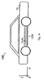
- the impact protection element according to the invention is used in particular in a vehicle, preferably as part or in a part of the vehicle body, preferably as a sill in a motor vehicle.
- the present invention relates to impact protection elements and in particular so-called crash absorbers in hollow elements of one or more fiber composite materials and in particular the production of so-called crash absorbers in hollow elements made of fiber composite materials.
- the object of the present invention is inter alia to provide an improved impact protection, namely inter alia by reinforcing a hollow component made from one or more fiber composite materials, in particular as a structural element, preferably for a vehicle body.
- the component to be provided is designed in hollow construction and is designed in particular with a detachable or releasable core, so that the production results in essentially a single operation.
- the preparation of the component as an impact protection element according to the invention in one operation with one or more embedded in a detachable core reinforcing elements offers procedural advantages in terms of time and / or material savings and also leads to particularly stable and the kinetic energy in an impact particularly well dissipating structures.
- the formation in the hollow component to be provided elements can be carried out in various configurations, for example in the form of a filled with a polyurethane material CFK hollow material body, preferably in the form of a cone, or in the form of a multiple undulated intermediate wall element, preferably in sinusoidal form.
- the use of the impact protection element according to the invention in the field of self-supporting bodies preferably in vehicles and in particular motor vehicles, e.g. at cars.
- the so-called sill can be designed as a hollow element.
- the production can be carried out according to the invention in particular in one step, e.g. via molded fiber preforms in an infusion process - e.g. RTM for soaking and curing.
- an infusion process e.g. RTM for soaking and curing.
- crash elements or crash elements can be used as composites with cores, e.g. made of polyurethane material.
- the crash elements to be provided in the hollow body, which according to the invention are also referred to as stabilizing / compressing elements, can be tapered, in particular conical, of any desired base, e.g. round, oval, angular or the like.
- crash elements or stabilizing / compressing elements in the form of arched partitions, which may e.g. wavy, angular, in any case, however, one or more times undulated are formed.
- the course of the undulation direction is perpendicular to the impact or crash direction, so that an end face or edge of the multiply undulated intermediate wall or the curved wall facing the suspected impact direction is formed or facing away.
- undulated shapes for example sinusoids
- the sinusoidal shape is introduced into the detachable core before the component production. After the infusion of the component for treatment with an impregnating agent, for example for resin treatment, then the core can be melted out. Then lies the multiply undulated intermediate wall, for example of sinusoidal, in the actual hollow component for the impact protection element according to the invention free and is only connected at its edges or end faces with the inside of the hollow member as the main component.
- the infusion and consequently the production of the hollow body for the impact protection element thus take place in one operation, wherein the component per se, as well as the reinforcement, are jointly infused in this type of production. That is, after encasing the hollow body stabilizing / compressing elements with the material forming the hollow body, a joint treatment with an impregnating agent, e.g. a resin or phenolic resin, so that in addition to the actual shell for the hollow body of the impact protection element and the stabilization / compression elements located there inside with the impregnating agent, e.g. the resin or phenolic resin, soaked and then cured.
- an impregnating agent e.g. a resin or phenolic resin
- one or a plurality of stabilization / compression elements can be introduced in cone form during production in a presented releasable core prior to component production.
- the structure thus obtained is combined with the fiber composite, e.g. CFRP material for the hollow body of the impact protection element surrounded, impregnated and cured.
- a correspondingly shaped core is respectively provided which may be formed from a releasable material or from a material remaining in the component (eg a foam). It is applied according to a wrapping material around this core presented, for example, a fiber material, preferably a CFRP material.
- the infusion takes place.
- the core or the core material for the hollow body of the impact protection element and depending on the nature of the hollow body stabilization / compression elements and their core can be melted.
- the actual stabilization / compression elements are then free in the hollow component for the impact protection element according to the invention and are only on the end faces, i. So connected to the end surfaces of the respective underlying hollow body stabilization / compression member with the main component in the form of the hollow body for the impact protection element according to the invention.
- the infusion and consequently the production of the hollow body for the impact protection element in a single operation again with the hollow body or the hollow member for the impact protection element according to the invention and the reinforcement on the hollow body stabilization / compression elements in this type of production together infused, ie with the impregnating agent, preferably the resin or phenolic resin, treated and cured.
- the impregnating agent preferably the resin or phenolic resin
- the core is essentially initially formed for the hollow body of the impact protection element. It will then be provided for the stabilization / compression elements required recesses. The recesses are then fitted with the stabilization / compression elements. The structure thus obtained is coated with the fibrous material, e.g. braided, wrapped or occupied.
- the component After applying the fibers, the component is placed, for example, in a tool and then infused with the impregnating agent, for example the resin or phenolic resin.
- the impregnating agent for example the resin or phenolic resin.
- the impact protection element is then manufactured, for example in the form of a CFRP body or a CFRP structure in a hollow mold the corresponding one or more stabilization / compression elements in their interior.
- the stabilization / compression elements are treated as well with the impregnating agent, as the outer shell, wherein means of the overlap points at the contact between the edges or end faces of the stabilization / compression elements and the underlying hollow body creates a compact component, ie a connection between the inner side or inner wall of the hollow body of the impact protection element according to the invention and the one or more stabilization / compression elements formed on the inside. It thus according to the invention eliminates the effort in a prefabricated hollow body subsequently introduce the stabilization / compression elements, because they can be mitgefert already during the infusion or impregnation of the main component and attached to the inside.
- this core material which initially surrounds the stabilization / compression elements, can be melted out, especially if it is a thermoplastic. It is conceivable, e.g. Here also the exuberant material to catch and reuse. Of course, in addition to the melting out, other possibilities of removing or releasing the core material are conceivable, e.g. in a chemical way.
- the impregnation in the corresponding mold can for example be carried out by means of a RTM process (resin transfer molding), wherein the introduced in the tool wrapped structure in the tool by introducing the impregnating agent, for example from an antechamber via pistons by means of channels in the molding of the tool with the Impregnated and then cured using pressure and / or heat.
- RTM process resin transfer molding
- a general infusion process which takes place under pressure, can be used, in which by means of a vacuum in the tool, the introduction of the impregnating agent can be supported.
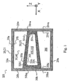
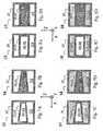
- Fig. 1 shows a schematic and sectional side view of a first embodiment of the impact protection element 10.
- This consists of a hollow body member 20 made of a carbon fiber material 21, in particular of a carbon fiber reinforced plastic material, and with respect to the suspected impact direction X a front wall or has a front wall element 20v and a rear wall or rear wall member 20h, and upper and lower walls or wall members 20o, 20u, respectively.
- these walls or wall elements 20v, 20h, 20o, 20u enclose the interior 20I of the hollow body 20 or hollow body element 20 underlying the impact protection element 10 and thus form its inner side 20i or inner surface 20i.
- This basic structure is substantially the same for all embodiments of the impact protection element 10 and is not repeated in each case of its occurrence in the individual embodiments of the impact protection element 10.
- a single stabilizing / compression element 30 is shown in the interior 201 of the hollow body 20 or hollow body member 20, however, it can be provided several stabilizing / compression elements 30, each perpendicular to the cutting direction before and / or behind the illustrated stabilization / Compression element 30 lie.
- the stabilization / compression element 30 provided in the interior 20l of the hollow body 20 or hollow body element 20 is designed in the form of a hollow body 40, namely with a shell 50, with an outer side 50a and an inner side 50i, which surround the interior 40I, 50I and optionally see the embodiments according to FIGS FIGS. 7B, 7D, 8B, 8D - Have a core portion 60 or a core member 60 with a corresponding filling or core material 60k.
- the shell 50 itself is formed by an upper wall 50o, a lower wall 50u and a front wall 50v facing the presumed impact direction X and a rear wall 50h facing away from the assumed impact direction X and the corresponding outer sides 50oa , 50ua, 50va, 50ha and insides 50oi, 50ui, 50vi and 50hi, respectively.
- the sheath 50 of the hollow body 40 of the stabilization / compression element 30 can in turn be formed from a CFK material 51, this may differ from the CFRP material 21 of the impact element 10 underlying hollow body member 20 or be identical to this.
- Another essential aspect of the present invention is that the inner sides 20vi and 20hi of the front and rear walls or wall elements 20v, 20h of the impact protection element 10 underlying hollow body 20 are connected to the outer sides 50va and 50ha of the corresponding front and rear walls or wall elements 50v and 50h of the hollow body mold 40 of the intended or intended stabilization / compression elements 30 in the interior I of the underlying hollow body element 20th
- the stabilizing / compressing element 30 with the hollow body mold 40 has a tapering profile, in particular a conical shape, wherein the hollow body mold 40 tapers from the side facing away from the presumed impact direction X to the side facing the presumed impact direction X.
- the rear wall 50h of the shell 50 has a larger footprint than the front wall 50v.
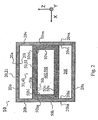
- the hollow body 40 of the stabilization / compression element 30 shown here has a substantially constant cross section along the presumed impact direction X, that is to say in the direction Z in the vertical or along the extension direction Y of the hollow body element 20 on which the impact protection element 10 according to the invention is based.
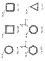
- the basic surface shapes for the sheaths 50 of the hollow bodies 40 of the respective stabilizing / compressing elements 30 of the embodiments of FIGS Fig. 1 and 2 are here assumed, for example, as circular, so that the hollow body forms 40 in the Fig. 1 and 2 are formed as a vertical truncated cone shape or as a vertical cylindrical shape.
- base surface shapes ie base surface shapes that deviate from the circular shape
- elliptical bases may be provided
- polygonal limited bases as in connection with the Fig. 12B is illustrated with a square, 12D with a uniform hexagon, 12E with a uniform octagon, and 12F with an equilateral triangle.
- more general rectangular shapes, diamonds, trapezoids, dragons etc. are conceivable.
- the corners or edges may, as related to the Fig. 12C and the basic square shape is shown to be rounded.
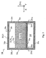
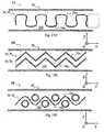
- the Fig. 3 shows another embodiment of the impact protection element 10, in which instead of the hollow body mold 40 for the stabilizing / compression elements 30, a structure is provided which has the structure of a multiply undulated, folded, kinked or corrugated intermediate wall element 70.
- the undulation direction U is identical to the vertical direction Z, ie the undulation itself, ie the waveform, the kinks, the folds, etc., extend from a planar structure in the Z direction and thus perpendicular to the presumed impact direction X and also perpendicular to the longitudinal direction Y of the impact element 10 underlying hollow body element 20th
- Fig. 3 which also shows a schematic and sectional side view of this embodiment of the impact protection element 10, looks like in the Fig. 1 and 2 also in the longitudinal direction Y on the structure according to the invention.
- the multiply undulated intermediate wall element 70 is preferably made of a CFRP material 71 and has, in addition to the upper surface or surface 70o and lower surface or surface 70u corresponding edge regions or edge surfaces 70v, 70h, in particular the presumed impact direction X facing front edge side 70v or edge surface 70v and the presumed impact direction X facing away from the rear edge side 70h or edge surface 70h are essential because they are just back with the inner sides or inner surfaces 20vi and 20hi facing with respect to the suspected impact direction X facing or facing front or rear wall elements or walls 20v and 20h are attached.
- FIGS. 4A to 6B show structures for impact protection elements 10 with the structures of Fig. 1 to 3 Have similarities.
- FIGS. 6A and 6B show an embodiment with a multiply undulated intermediate wall 70, which here forms a separately provided stabilizing / compression element 30, the arrangement being considered again in the presumed impact direction X, so that in the drawing on the front edge 70v or on the front edge region 70v is looking.
- Figs. 7A to 7D show schematically sectional side views of various embodiments of the impact protection element 10 according to the invention with one or more conically extending stabilization / compression elements 30 with hollow body shape 40th
- FIG. 7A to 7D differ only with regard to their filling status of the respective cavities or inner regions 201 of the hollow body element 20 and 40I, 50I of the hollow body mold 40 and the shell 50 of the respective stabilizing / compressing element 30 which is the basis of the impact protection element 10.
- the inner regions 40l, 50l of the stabilization / compression elements 30 are filled with a core material 60k as core region 60 or core element 60.
- this core region 60 or the core element 60 may usually be initially introduced from the core material 60k or be surrounded by the corresponding shell 50 for the hollow body shape 40.
- Fig. 7B is the stabilization / compression elements 30 filled, the interior 201 of the underlying hollow body member 20 but unfilled, so empty.
- the interior 20I of the underlying hollow body element 20 is filled with a core material 20k.
- FIGS. 8A and 8D also show in a schematic and sectional side view embodiments of the impact protection element 10 with stabilizing / compression elements 30 in hollow body shape 40, but here, in contrast to the embodiments of Figs. 7A to 7D , with in the suspected direction of impact X constant cross-section, eg in cylindrical form. Otherwise, the structures are those of the Figs. 7A to 7D to be evaluated analogously.
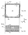
- Figs. 9A to 9C show in the manner of an exploded view an embodiment of the impact protection element 10 in a schematic and sectional side view, wherein the Fig. 9A essentially the hollow body element 20 on which the impact protection element 10 according to the invention is based Figs. 9B and 9C on the other hand illustrate in each case a conical or a cylindrical stabilization / compression element 30 in a hollow body shape.
- FIG. 10A and 10B in a schematic and sectional side view also in the manner of an exploded view of an embodiment of the impact protection element 10, wherein the Fig. 10A in turn based on the impact protection element 10 according to the invention lying hollow body element 20 and the Fig. 10B a corresponding stabilizing / compression element 30 in the manner of a multiply undulated intermediate wall 70 represents.
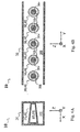
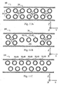
- Figs. 11A to 11C show in schematic and sectional top view of various embodiments of the impact protection element 10, wherein a plurality of rows of stabilizing / compression elements 30 are provided in hollow body 40.
- identical hollow body molds 40 are provided for the stabilizing / compressing elements 30 and extend parallel to one another in the Y direction and in the Z direction.
- Fig. 11C are also two parallel to each other in the Y direction extending rows of pluralities of stabilization / compression elements 30 before, but these are offset from each other, virtually arranged on the gap.
- FIG. 11B there is a subdivision of the plurality of provided stabilization / compression elements 30.
- a single row with a plurality of stabilizing / compression elements 30 is provided.
- the stabilization / compression elements 30 are again in two parallel rows.
- FIGS. 13A to 13E show various embodiments of the impact protection element 10 using at least one stabilizing / compressing element 30 in the form of a multi-undulating intermediate wall element 70.
- the embodiments of the Figs. 13A to 13D formed in each case with a single stabilizing / compressing element 30 in the manner of a multiply undulated wall element 70, namely in its cross-sectional shape with a sawtooth course, a step-like course, a wave-shaped, preferably sinusoidal course or a Course with ovals, based on the step-shaped course Fig. 13B ,
- two stabilization / compression elements 30 are each shown with a sawtooth extending multiple undulated intermediate wall 70.
- other courses may be provided multiple times, and the undulated intermediate wall elements 70 need not be of identical shape.
- the different structural features in the direction Y can also alternate, that is, in each case a multiply undulated intermediate wall element 70 can be formed in sections with different undulations.
- a multi-undulated intermediate wall element 70 and a plurality of hollow-shape stabilization / compression elements 30 are combined with one another. Again, any combinations are conceivable.
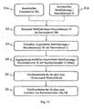
- the Fig. 15 illustrates an embodiment of the method according to the invention for producing an impact protection element 10 according to the invention.
- steps S1a and S1b the core material 20k for the hollow body element 20 on which the impact protection element 10 according to the invention is based and the stabilization / compression elements 30 are provided.
- step S2 the one or more stabilization / compression elements 30 are embedded in the core material 20k. This can be done either by forming corresponding recesses in the core material 20k provided and by inserting or introducing the one or more stabilizing / compressing elements 30 into the recesses or by presenting the one or more stabilizing / compressing elements 30 and by corresponding wrapping with the provided core material 20k.
- step S3 the embedded or embedding structure thus obtained with the embedded stabilization / compression elements 30 is enveloped with a CFRP material 21 for the hollow body element 20 on which the impact protection element 10 according to the invention is based.
- step S4 the structure thus obtained is impregnated with the coated embedded stabilizing / compressing elements 30 with a impregnating agent 23.
- a impregnating agent 23 This may be a resin or phenolic resin or the like.
- steps S5 and S6 post-processing of the impregnated structure thus obtained may take place.
- step S5 in a curing process using heat and / or pressure, ie the composite material of fiber material and resin matrix is completed and / or the stabilization / compression elements 30 on the inner side 20i, 25i of the impact protection element 10 of the invention underlying hollow body member 20 are attached as a shell 25.
- Steps S4 of impregnation and S5 of curing and / or curing need not be separately executable, e.g. in a VAP method or the like, in which the hardening in S5 is defined as a subsequent step.
- the hardening in S5 is defined as a subsequent step.
- RTM method the hardening and / or the joining of step S5 already takes place simultaneously with the process of impregnating or infusing step S4, namely when the tool used is under pressure and temperature.
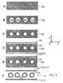
- FIGS. 16A to 16E show in schematic and sectional top view various intermediate stages in the manufacture of an impact protection element 10 according to the invention.
- a core material 20k is presented for the hollow body element 20 on which the impact protection element 10 according to the invention is based.
- intermediate state recesses 20A are then introduced into the presented core material 20k, which correspond in shape to the stabilization / compression elements 30 to be introduced and serve to receive them.
- the bonding of the stabilization / compression elements 30 on the inner side 25i of the shell 25 can take place simultaneously with the impregnation, for example if the impregnation takes place under pressure and / or temperature, for example in a molding tool; but there are also separate operations conceivable and possible, in which the structure is first impregnated and then further treated to attach the stabilization / compression elements on the inside 25i of the shell 25.
Claims (23)
- Élément de protection anti-impacts (10) pour une carrosserie de véhicule destiné à encaisser et/ou dissiper une énergie cinétique lors d'un impact,- qui comprend un élément de corps creux (20) avec un composite en fibres ou formé d'un tel composite en fibres,- dans lequel l'élément de corps creux (20) comprend un élément de paroi antérieur (20v) tourné vers une direction d'impact attendue (X) et un élément de paroi postérieur (20h) détourné d'une direction d'impact attendue (X),- dans lequel l'élément de corps creux (20) comporte dans son intérieur (201) un ou plusieurs éléments de stabilisation/écrasement (30),- dans lequel lesdits un ou plusieurs éléments de stabilisation/écrasement (30) sont rapportés sur les faces intérieures (20vi, 20hi) des éléments de paroi antérieur et postérieur (20v, 20h) tourné vers et détourné de la direction d'impact attendue (X), eta) dans lequel un ou plusieurs éléments de stabilisation/écrasement (30) sont réalisés sous la forme d'un corps creux (40), etb) dans lequel un ou plusieurs éléments de stabilisation/écrasement (30) sont réalisés sous la forme d'un élément de paroi intermédiaire (70) à ondulations multiples.
- Élément de protection anti-impacts (10) selon la revendication 1, dans lequel le corps creux (40) d'un élément de stabilisation/écrasement (30) est réalisé avec un diamètre ou une section constante, s'étendant en particulier depuis un côté (50h, 50ha) détourné de la direction d'impact attendue (X) vers un côté (50v, 50va) tourné vers la direction d'impact attendue (X).
- Élément de protection anti-impacts (10) selon l'une des revendications précédentes, dans lequel le corps creux (40) d'un élément de stabilisation/écrasement (30) présente la forme d'un cylindre - en particulier avec une surface terminale ou une surface de base de forme circulaire et/ou elliptique -, d'un cube ou d'un prisme, en particulier avec des surfaces terminales sous la forme d'un polygone régulier ou irrégulier, en particulier respectivement sous une forme perpendiculaire ou oblique.
- Élément de protection anti-impacts (10) selon l'une des revendications précédentes, dans lequel le corps creux (40) d'un élément de stabilisation/écrasement (30) est réalisé de manière conique ou en se rétrécissant, s'étendant en particulier depuis un côté (50h, 50ha) détourné de la direction d'impact attendue (X) vers un côté (50v, 50va) tourné vers la direction d'impact attendue (X).
- Élément de protection anti-impacts (10) selon l'une des revendications précédentes 1 ou 3, dans lequel le corps creux (40) d'un élément de stabilisation/écrasement (30) présente la forme d'un tronc d'un corps géométrique, de préférence d'un tronc de cône - en particulier avec des surfaces terminales ou des surfaces de base de forme circulaire et/ou elliptique - ou d'un tronc de pyramide - en particulier avec des surfaces terminales sous la forme d'un polygone régulier ou irrégulier, s'étendant en particulier depuis un côté (50h, 50ha) détourné de la direction d'impact attendue (X) vers un côté (50v, 50va) tourné vers la direction d'impact attendue (X).
- Élément de protection anti-impacts (10) selon l'une des revendications précédentes, dans lequel le corps creux (40) d'un élément de stabilisation/écrasement (30) est réalisé avec ou à partir d'au moins un composite en fibres.
- Élément de protection anti-impacts (10) selon l'une des revendications précédentes, dans lequel le corps creux (40) d'un élément de stabilisation/écrasement (30) est rempli dans son intérieur (401) avec un matériau (60), en particulier avec un matériau en forme de mousse, de préférence avec un matériau en polymère, un matériau métallique, un matériau en PU ou en polyuréthane.
- Élément de protection anti-impacts (10) selon l'une des revendications précédentes, dans lequel il est prévu un agencement d'une pluralité d'éléments de stabilisation/écrasement (30) sous la forme de corps creux (40), en particulier sous la forme d'une ou plusieurs rangées qui s'étendent perpendiculairement à la direction d'impact attendue (X) et/ou dans une direction d'extension longitudinale (Y) de l'élément de corps creux (20) de l'élément de protection anti-impacts (10).
- Élément de protection anti-impacts (10) selon l'une des revendications précédentes, dans lequel un corps creux respectif (40) d'un élément de stabilisation/écrasement (30) en forme de corps creux est rapporté avec les faces extérieures (50va, 50ha) d'éléments de paroi antérieur ou postérieur (50v, 50h) à titre de surfaces terminales, sur les faces intérieures (20vi, 20hi) des éléments de paroi antérieur ou postérieur (20v, 20h), de l'élément de corps creux (20) de l'élément de protection anti-impacts (10), tourné vers ou détourné de la direction d'impact attendue (X).
- Élément de protection anti-impacts (10) selon l'une des revendications précédentes, dans lequel une direction d'ondulation (U) des ondulations d'un élément de stabilisation/écrasement (30) sous la forme d'un élément de paroi intermédiaire (70) à ondulations multiples, s'étend perpendiculairement à la direction d'impact attendue (X) et/ou à une direction d'extension longitudinale (Y) de l'élément de corps creux (20) de l'élément de protection anti-impacts (10).
- Élément de protection anti-impacts (10) selon l'une des revendications précédentes, dans lequel un élément de paroi intermédiaire (70) à ondulations multiples d'un élément de stabilisation/écrasement (30) comporte une arête antérieure (70v) et une arête postérieure (70h), qui sont rapportées sur les faces intérieures (20vi, 20hi) des éléments de paroi antérieur et postérieur (20v, 20h), de l'élément de corps creux (20) de l'élément de protection anti-impacts (10), tourné vers ou détourné de la direction d'impact attendue (X).
- Élément de protection anti-impacts (10) selon l'une des revendications précédentes, dans lequel un élément de paroi intermédiaire (70) à ondulations multiples d'un élément de stabilisation/écrasement (30) comporte un tronçon (72) à ondulations multiples, en particulier en section transversale avec un tracé sous la forme d'une dent de scie simple ou multiple, avec des flancs obliques ou perpendiculaires, sous la forme d'un gradin simple ou multiple, sous la forme d'un ovale simple ou multiple, d'un gradin arrondi simple ou multiple, une forme d'onde simple ou multiple, une forme sinusoïdale simple ou multiple, ou une combinaison de ces formes.
- Élément de protection anti-impacts (10) selon l'une des revendications précédentes, dans lequel un élément de paroi intermédiaire (70) a ondulations multiples d'un élément de stabilisation/écrasement (30) est réalisé avec ou à partir d'au moins un composite en fibres (71)
- Élément de protection anti-impacts (10) selon l'une des revendications précédentes, qui est rempli dans son intérieur (201) partiellement ou totalement d'un matériau d'âme (20k), ledit matériau d'âme (20k) noyant en particulier un ou plusieurs éléments de stabilisation/écrasement (30).
- Élément de protection anti-impacts (10) selon l'une des revendications précédentes, dans lequel un composite en fibres respectif (21, 51, 71) comprend, ou est formé par, un ou plusieurs matériaux choisis parmi le groupe qui comporte les matières plastiques renforcées par des fibres, les matériaux à base de verre, les matériaux aramides, les matériaux en fibres naturelles, les matériaux basaltiques, et leurs combinaisons.
- Procédé pour fabriquer un élément de protection anti-impacts (10) selon l'une des revendications 1 à 15, comprenant les étapes consistant à :(A) mettre à disposition un matériau d'âme (20k),(B) mettre à disposition un ou plusieurs éléments de stabilisation/écrasement (30),(C) noyer des éléments de stabilisation/écrasement (30) dans le matériau d'âme (20k),(D) enrober partiellement ou totalement la structure obtenue dans l'étape (C), constituée d'éléments de stabilisation/écrasement (30) noyés dans un matériau d'âme (20k) avec un composite en fibres (21) ou une ébauche (22) d'un composite en fibres (21) à titre d'enveloppe (25),(E) imprégner la structure obtenue dans l'étape (D), constituée d'éléments de stabilisation/écrasement (30) noyés dans un matériau d'âme (20k) et enrobés partiellement ou totalement avec un composite en fibres (21) ou une ébauche (22) d'un composite en fibres (21) à titre d'enveloppe (25), avec un agent d'imprégnation (23), et(F) relier les éléments de stabilisation/écrasement (30) avec la face intérieure (25i) de l'enveloppe (25).
- Procédé selon la revendication 16, dans lequel l'étape consistant à noyer (C) les éléments de stabilisation/écrasement (30) dans le matériau d'âme (20k) a lieu en ménageant dans le matériau d'âme (20k) mis à disposition une ou plusieurs cavités ajustées aux éléments de stabilisation/écrasement (30), et en posant ou en introduisant alors les éléments de stabilisation/écrasement (30) dans les cavités.
- Procédé selon la revendication 16, dans lequel l'étape consistant à noyer (C) les éléments de stabilisation/écrasement (30) dans le matériau d'âme (20k) un lieu en posant au préalable lesdits un ou plusieurs éléments de stabilisation/écrasement (10), et en les noyant alors avec le matériau d'âme (20k) mis à disposition.
- Procédé selon l'une des revendications précédentes 16 à 18, dans lequel l'étape consistant à enrober (D) partiellement ou totalement avec un composite en fibres (21) ou avec une ébauche (22) d'un composite en fibres (21) a lieu en ce que la structure à enrober formée du matériau d'âme (20k) et d'un ou plusieurs éléments de stabilisation/écrasement (30) est enveloppée, entourée d'un tressage, entouré d'un bobinage et/ou recouverte avec le composite en fibres (21) ou avec l'ébauche (22) du composite en fibres (21).
- Procédé selon l'une des revendications précédentes 16 à 19, dans lequel l'étape consistant à imprégner (E) la structure enrobée a lieu en appliquant ou en introduisant l'agent d'imprégnation (23), en particulier un matériau de matrice en polymère et de préférence une résine ou une résine phénolique, en particulier dans le cadre d'un procédé par infusion et/ou d'un procédé RTM, par exemple une infusion sous vide et/ou en association avec un outil d'imprégnation ou un moule d'imprégnation correspondant, de préférence de configuration fermée.
- Procédé selon l'une des revendications précédentes 16 à 20, dans lequel lors du traitement ultérieur (F), la structure imprégnée et enrobée est durcie, en particulier par application de température et/ou de pression, de préférence simultanément avec l'imprégnation (E)
- Procédé selon l'une des revendications précédentes 16 à 21, dans lequel lors du traitement ultérieur (F), le matériau d'âme (20k) contenu dans la structure imprégnée enrobée est dissous, en particulier par fusion en appliquant une montée en température, ou par des attaques chimiques, de sorte qu'au moins une partie de l'intérieur (201) de l'élément creux (20) de l'élément de protection anti-impacts (10) demeure avec une ou plusieurs cavités.
- Utilisation d'un élément de protection anti-impacts (10) selon l'une des revendications 1 à 15 dans un véhicule, de préférence comme partie d'une carrosserie de véhicule ou dans une partie de carrosserie du véhicule, de préférence comme longeron dans un véhicule automobile.
Applications Claiming Priority (1)
| Application Number | Priority Date | Filing Date | Title |
|---|---|---|---|
| DE102010003497.5A DE102010003497B4 (de) | 2010-03-31 | 2010-03-31 | Verfahren zur Herstellung eines Aufprallschutzelementes |
Publications (2)
| Publication Number | Publication Date |
|---|---|
| EP2371677A1 EP2371677A1 (fr) | 2011-10-05 |
| EP2371677B1 true EP2371677B1 (fr) | 2014-07-23 |
Family
ID=44278991
Family Applications (1)
| Application Number | Title | Priority Date | Filing Date |
|---|---|---|---|
| EP11157599.9A Active EP2371677B1 (fr) | 2010-03-31 | 2011-03-10 | Elément de pare-chocs, son utilisation et procédé de fabrication |
Country Status (3)
| Country | Link |
|---|---|
| US (1) | US8608232B2 (fr) |
| EP (1) | EP2371677B1 (fr) |
| DE (1) | DE102010003497B4 (fr) |
Families Citing this family (29)
| Publication number | Priority date | Publication date | Assignee | Title |
|---|---|---|---|---|
| US8608230B2 (en) * | 2012-04-13 | 2013-12-17 | Toyota Motor Engineering & Manufacturing North America, Inc. | Localized energy dissipation structures for vehicles |
| DE102012206032B4 (de) * | 2012-04-13 | 2017-06-29 | Bayerische Motoren Werke Aktiengesellschaft | Strukturbauteil einer Kraftfahrzeugkarosserie |
| DE102012013881A1 (de) | 2012-07-12 | 2013-01-24 | Daimler Ag | Strukturbauteil für eine Kraftfahrzeug-Karosserie und Verfahren zu dessen Herstellung |
| JP5596753B2 (ja) * | 2012-08-03 | 2014-09-24 | アイシン精機株式会社 | 衝撃吸収部材 |
| DE102012214748B4 (de) * | 2012-08-20 | 2021-10-21 | Bayerische Motoren Werke Aktiengesellschaft | Kraftfahrzeug mit einem Schweller |
| DE102012025334B4 (de) * | 2012-12-21 | 2017-04-27 | Audi Ag | Strukturbauteil für ein Fahrzeug zur Aufnahme von in einer Energieeinleitungsrichtung eingeleiteter kinetischer Energie |
| DE102013002537A1 (de) * | 2013-02-14 | 2014-08-14 | Daimler Ag | Schweller-Bodenstruktur-Anordnung |
| DE102013002503B4 (de) | 2013-02-14 | 2015-10-22 | Daimler Ag | Strukturbauteil für eine Kraftfahrzeugkarosserie und Kraftfahrzeugkarosserie |
| DE102013106073A1 (de) * | 2013-06-12 | 2014-12-18 | Leichtbau-Zentrum Sachsen Gmbh | Integraler Längsträger für Kraftfahrzeuge |
| DE102013215793A1 (de) * | 2013-08-09 | 2015-02-12 | Volkswagen Aktiengesellschaft | Fahrzeugkarosserie |
| DE102013018324A1 (de) * | 2013-10-31 | 2015-04-30 | GM Global Technology Operations LLC (n. d. Ges. d. Staates Delaware) | Kraftfahrzeugkarosserie |
| KR102206337B1 (ko) * | 2014-03-18 | 2021-01-21 | 데이진 가부시키가이샤 | 중공 구조체 및 차량용 부품 |
| DE102014016024A1 (de) | 2014-10-29 | 2016-05-04 | Daimler Ag | Fahrzeug mit Energieabsorptionseinheit |
| DE102015207376A1 (de) * | 2015-04-22 | 2016-10-27 | Bayerische Motoren Werke Aktiengesellschaft | Kraftfahrzeug |
| DE102015222055A1 (de) * | 2015-11-10 | 2017-05-11 | Bayerische Motoren Werke Aktiengesellschaft | Strukturbauteil für ein Kraftfahrzeug |
| KR101795236B1 (ko) | 2016-04-12 | 2017-11-08 | 현대자동차주식회사 | 충격흡수 유닛, 충격흡수 유닛 제조방법 및 충격흡수 보강재 |
| US10766536B2 (en) * | 2016-09-07 | 2020-09-08 | Thunder Power New Energy Vehicle Development Company Limited | Lateral energy absorption system |
| US10336373B2 (en) | 2016-09-07 | 2019-07-02 | Thunder Power New Energy Vehicle Development Company Limited | Lateral energy absorption system |
| US10160499B2 (en) * | 2017-04-21 | 2018-12-25 | Ford Global Technologies, Llc | Rocker assembly with a pultruded load distribution insert |
| DE102017006057B4 (de) * | 2017-06-27 | 2021-05-12 | Audi Ag | Crashelement |
| US10363968B2 (en) | 2017-11-08 | 2019-07-30 | Ford Global Technologies, Llc | Rocker assembly for autonomous vehicle |
| MX2020008090A (es) * | 2018-01-31 | 2021-07-14 | Nippon Steel Corp | Miembro de armazón de vehículo y vehículo. |
| US11077812B2 (en) | 2018-02-27 | 2021-08-03 | GM Global Technology Operations LLC | Composite energy-absorbing assembly |
| US20190264769A1 (en) * | 2018-02-27 | 2019-08-29 | GM Global Technology Operations LLC | Composite energy-absorbing assembly having discrete energy-absorbing elements supported by a carrier plate |
| JP6676092B2 (ja) * | 2018-03-28 | 2020-04-08 | 株式会社豊田自動織機 | 車体補強構造、及び車体補強構造の製造方法 |
| DE102019208224A1 (de) * | 2019-06-05 | 2020-05-28 | Audi Ag | Crashstruktur für ein Fahrzeug |
| CN112339865A (zh) * | 2020-11-25 | 2021-02-09 | 浙江吉利控股集团有限公司 | 一种碰撞吸能结构、车身结构件及车辆 |
| US11447185B2 (en) * | 2021-02-16 | 2022-09-20 | GM Global Technology Operations LLC | Enhanced energy absorption rocker assembly |
| FR3122135B1 (fr) * | 2021-04-27 | 2024-02-16 | Conseil & Technique | Pièce composite sacrificielle absorbant l’énergie lors d’une collision d’un véhicule avec un objet impactant |
Family Cites Families (27)
| Publication number | Priority date | Publication date | Assignee | Title |
|---|---|---|---|---|
| FR2288648A1 (fr) * | 1974-03-05 | 1976-05-21 | Peugeot & Renault | Pare-chocs composite absorbeur d'energie |
| US4227593A (en) * | 1976-10-04 | 1980-10-14 | H. H. Robertson Company | Kinetic energy absorbing pad |
| JPS641116U (fr) * | 1987-06-23 | 1989-01-06 | ||
| JPH01103417U (fr) * | 1987-12-28 | 1989-07-12 | ||
| US5306068A (en) * | 1991-08-30 | 1994-04-26 | Toray Industries Inc. | Automobile door |
| JP3144054B2 (ja) * | 1992-05-28 | 2001-03-07 | 株式会社豊田自動織機製作所 | エネルギー吸収部材 |
| US5474405A (en) * | 1993-03-31 | 1995-12-12 | Societe Civile Des Brevets Henri C. Vidal | Low elevation wall construction |
| CA2134943A1 (fr) | 1993-11-05 | 1995-05-06 | Minoru Sugawara | Poutre de pare-chocs obtenue par le procede de moulage par soufflage |
| DE4439221C2 (de) * | 1994-11-03 | 1997-10-16 | Katzbach Kunststoffwerk Gmbh | Verkleidungsteil, insbesondere Türverkleidungsträger, für ein Kraftfahrzeug |
| US5746419A (en) * | 1996-10-16 | 1998-05-05 | General Motors Corporation | Energy absorbing device |
| DE19736839A1 (de) | 1997-08-23 | 1999-02-25 | Volkswagen Ag | Deformationsstruktur für den Insassenschutz in Fahrzeugen |
| DE10037593B4 (de) * | 2000-08-02 | 2005-09-29 | Göpfert, Reinhard, Dipl.-Ing. | Aufprallschutz |
| US6375251B1 (en) * | 2000-12-20 | 2002-04-23 | Hamid Taghaddos | Energy-absorbing structure for an automobile |
| US6461076B1 (en) * | 2001-01-03 | 2002-10-08 | Energy Absorption Systems, Inc. | Vehicle impact attenuator |
| US6793274B2 (en) * | 2001-11-14 | 2004-09-21 | L&L Products, Inc. | Automotive rail/frame energy management system |
| DE10159067A1 (de) | 2001-12-01 | 2003-06-26 | Daimler Chrysler Ag | Faserverbund-Crashstruktur |
| US7226120B2 (en) * | 2002-03-15 | 2007-06-05 | Honda Giken Kogyo Kabushiki Kaisha | Skeleton member structure |
| US6923499B2 (en) * | 2002-08-06 | 2005-08-02 | L & L Products | Multiple material assembly for noise reduction |
| JP3888630B2 (ja) | 2002-12-04 | 2007-03-07 | 川崎重工業株式会社 | エネルギー吸収部材及びそれを用いるヘリコプタの耐衝撃構造 |
| US20050016807A1 (en) * | 2003-07-21 | 2005-01-27 | L&L Products, Inc. | Crash box |
| US7842378B2 (en) * | 2004-01-06 | 2010-11-30 | Kabushiki Kaisha Toyota Jidoshokki | Energy absorber and method for manufacturing the same |
| ATE404407T1 (de) * | 2004-06-16 | 2008-08-15 | Jacob Composite Gmbh | Bauteil zur energieaufnahme bei einem aufprall |
| GB2422645B (en) * | 2005-02-01 | 2009-05-13 | Autoliv Dev | Improvements in or relating to a safety arrangement |
| DE102005017956B4 (de) | 2005-04-18 | 2013-04-04 | Ise Automotive Gmbh | Stoßenergieaufnahmevorrichtung |
| FR2904602B1 (fr) * | 2006-08-01 | 2009-04-10 | Airbus France Sas | Encadrement de porte pour aeronef |
| DE102008015960B4 (de) | 2008-03-20 | 2012-01-12 | Deutsches Zentrum für Luft- und Raumfahrt e.V. | Fahrzeug mit mindestens einer Energieabsorptionsvorrichtung zur Absorption von Aufprallenergie |
| US7866716B2 (en) * | 2008-04-08 | 2011-01-11 | Flex-N-Gate Corporation | Energy absorber for vehicle |
-
2010
- 2010-03-31 DE DE102010003497.5A patent/DE102010003497B4/de not_active Expired - Fee Related
-
2011
- 2011-03-10 EP EP11157599.9A patent/EP2371677B1/fr active Active
- 2011-03-30 US US13/075,562 patent/US8608232B2/en active Active
Also Published As
| Publication number | Publication date |
|---|---|
| US20120074735A1 (en) | 2012-03-29 |
| EP2371677A1 (fr) | 2011-10-05 |
| US8608232B2 (en) | 2013-12-17 |
| DE102010003497B4 (de) | 2018-04-05 |
| DE102010003497A1 (de) | 2011-10-06 |
Similar Documents
| Publication | Publication Date | Title |
|---|---|---|
| EP2371677B1 (fr) | Elément de pare-chocs, son utilisation et procédé de fabrication | |
| EP2651751B1 (fr) | Élément modulaire de carrosserie et son procédé de fabrication | |
| EP2511084B1 (fr) | Elément de noeud en matière plastique renforcée de fibres et procédé de fabrication et d'utilisation associé | |
| EP1985465B1 (fr) | Rayon, roue et procédé de fabrication d'un rayon, en particulier pour vélos | |
| EP3218170B1 (fr) | Élément structural en matériau renforcé par des fibres et son procédé de fabrication | |
| EP2465665B1 (fr) | Procédé de fabrication d'un composant en matériau hybride | |
| EP3052306B1 (fr) | Élément en matériau composite renforcé par fibres et procédé de fabrication d'un élément en matériau composite renforcé par fibres | |
| DE102011004249A1 (de) | Faserverbund-Bauteil, das eine Tragstruktur für ein Kraftfahrzeug bildet, und Verfahren zur Herstellung des Faserverbund-Bauteils | |
| WO2012055489A1 (fr) | Support élastique conçu pour un composant et son procédé de production | |
| EP3057779B1 (fr) | Procédé de production d'un élément structural composite renforcé par des fibres | |
| EP3490782B1 (fr) | Procédé pour la fabrication d'une pièce composite à fibres multicouche, tridimensionnelle | |
| DE102008029518B4 (de) | Verfahren zur Herstellung von Faserverbundbauteilen und Faserverbundbauteile | |
| DE102016101663A1 (de) | Holmgurt und Herstellungsverfahren | |
| DE102012013881A1 (de) | Strukturbauteil für eine Kraftfahrzeug-Karosserie und Verfahren zu dessen Herstellung | |
| EP2740588A1 (fr) | Elément sandwich, partie de carrosserie d'un véhicule automobile et procédé de fabrication d'un élément sandwich | |
| EP3165431B1 (fr) | Structure de liaison comprenant au moins un composant en corps creux à double paroi, procédé de fabrication et carrosserie de véhicule | |
| DE102013020871A1 (de) | Strukturbauteil für ein Kraftfahrzeug | |
| EP3291972B1 (fr) | Composite hybride à matériaux multiples renforcé par un textile et son procédé de fabrication | |
| DE102011003747A1 (de) | Faserverstärktes Bauteil und Verfahren zur Herstellung eines faserverstärkten Bauteils | |
| DE102008023208A1 (de) | Bauteil in Hybridbauweise | |
| EP2873518B1 (fr) | Procédé de fabrication d'un composant en composite renforcé en fibres | |
| DE102011107512B4 (de) | Duktile CFK-Struktur | |
| WO2019020703A1 (fr) | Procédé de fabrication d'un ressort hélicoïdal | |
| EP2719521A1 (fr) | Gousset en élastomère | |
| DE102018204541A1 (de) | Achsstrebe für ein Fahrzeug |
Legal Events
| Date | Code | Title | Description |
|---|---|---|---|
| PUAI | Public reference made under article 153(3) epc to a published international application that has entered the european phase |
Free format text: ORIGINAL CODE: 0009012 |
|
| AK | Designated contracting states |
Kind code of ref document: A1 Designated state(s): AL AT BE BG CH CY CZ DE DK EE ES FI FR GB GR HR HU IE IS IT LI LT LU LV MC MK MT NL NO PL PT RO RS SE SI SK SM TR |
|
| AX | Request for extension of the european patent |
Extension state: BA ME |
|
| 17P | Request for examination filed |
Effective date: 20120209 |
|
| GRAP | Despatch of communication of intention to grant a patent |
Free format text: ORIGINAL CODE: EPIDOSNIGR1 |
|
| RAP1 | Party data changed (applicant data changed or rights of an application transferred) |
Owner name: BENTELER SGL GMBH & CO. KG |
|
| GRAS | Grant fee paid |
Free format text: ORIGINAL CODE: EPIDOSNIGR3 |
|
| GRAA | (expected) grant |
Free format text: ORIGINAL CODE: 0009210 |
|
| AK | Designated contracting states |
Kind code of ref document: B1 Designated state(s): AL AT BE BG CH CY CZ DE DK EE ES FI FR GB GR HR HU IE IS IT LI LT LU LV MC MK MT NL NO PL PT RO RS SE SI SK SM TR |
|
| REG | Reference to a national code |
Ref country code: GB Ref legal event code: FG4D Free format text: NOT ENGLISH |
|
| REG | Reference to a national code |
Ref country code: CH Ref legal event code: EP |
|
| REG | Reference to a national code |
Ref country code: IE Ref legal event code: FG4D Free format text: LANGUAGE OF EP DOCUMENT: GERMAN |
|
| REG | Reference to a national code |
Ref country code: AT Ref legal event code: REF Ref document number: 678682 Country of ref document: AT Kind code of ref document: T Effective date: 20140815 |
|
| REG | Reference to a national code |
Ref country code: DE Ref legal event code: R096 Ref document number: 502011003817 Country of ref document: DE Effective date: 20140904 |
|
| REG | Reference to a national code |
Ref country code: NL Ref legal event code: VDEP Effective date: 20140723 |
|
| REG | Reference to a national code |
Ref country code: LT Ref legal event code: MG4D |
|
| PG25 | Lapsed in a contracting state [announced via postgrant information from national office to epo] |
Ref country code: BG Free format text: LAPSE BECAUSE OF FAILURE TO SUBMIT A TRANSLATION OF THE DESCRIPTION OR TO PAY THE FEE WITHIN THE PRESCRIBED TIME-LIMIT Effective date: 20141023 Ref country code: ES Free format text: LAPSE BECAUSE OF FAILURE TO SUBMIT A TRANSLATION OF THE DESCRIPTION OR TO PAY THE FEE WITHIN THE PRESCRIBED TIME-LIMIT Effective date: 20140723 Ref country code: SE Free format text: LAPSE BECAUSE OF FAILURE TO SUBMIT A TRANSLATION OF THE DESCRIPTION OR TO PAY THE FEE WITHIN THE PRESCRIBED TIME-LIMIT Effective date: 20140723 Ref country code: PT Free format text: LAPSE BECAUSE OF FAILURE TO SUBMIT A TRANSLATION OF THE DESCRIPTION OR TO PAY THE FEE WITHIN THE PRESCRIBED TIME-LIMIT Effective date: 20141124 Ref country code: GR Free format text: LAPSE BECAUSE OF FAILURE TO SUBMIT A TRANSLATION OF THE DESCRIPTION OR TO PAY THE FEE WITHIN THE PRESCRIBED TIME-LIMIT Effective date: 20141024 Ref country code: NO Free format text: LAPSE BECAUSE OF FAILURE TO SUBMIT A TRANSLATION OF THE DESCRIPTION OR TO PAY THE FEE WITHIN THE PRESCRIBED TIME-LIMIT Effective date: 20141023 Ref country code: FI Free format text: LAPSE BECAUSE OF FAILURE TO SUBMIT A TRANSLATION OF THE DESCRIPTION OR TO PAY THE FEE WITHIN THE PRESCRIBED TIME-LIMIT Effective date: 20140723 Ref country code: LT Free format text: LAPSE BECAUSE OF FAILURE TO SUBMIT A TRANSLATION OF THE DESCRIPTION OR TO PAY THE FEE WITHIN THE PRESCRIBED TIME-LIMIT Effective date: 20140723 |
|
| PG25 | Lapsed in a contracting state [announced via postgrant information from national office to epo] |
Ref country code: NL Free format text: LAPSE BECAUSE OF FAILURE TO SUBMIT A TRANSLATION OF THE DESCRIPTION OR TO PAY THE FEE WITHIN THE PRESCRIBED TIME-LIMIT Effective date: 20140723 Ref country code: IS Free format text: LAPSE BECAUSE OF FAILURE TO SUBMIT A TRANSLATION OF THE DESCRIPTION OR TO PAY THE FEE WITHIN THE PRESCRIBED TIME-LIMIT Effective date: 20141123 Ref country code: HR Free format text: LAPSE BECAUSE OF FAILURE TO SUBMIT A TRANSLATION OF THE DESCRIPTION OR TO PAY THE FEE WITHIN THE PRESCRIBED TIME-LIMIT Effective date: 20140723 Ref country code: RS Free format text: LAPSE BECAUSE OF FAILURE TO SUBMIT A TRANSLATION OF THE DESCRIPTION OR TO PAY THE FEE WITHIN THE PRESCRIBED TIME-LIMIT Effective date: 20140723 Ref country code: LV Free format text: LAPSE BECAUSE OF FAILURE TO SUBMIT A TRANSLATION OF THE DESCRIPTION OR TO PAY THE FEE WITHIN THE PRESCRIBED TIME-LIMIT Effective date: 20140723 Ref country code: CY Free format text: LAPSE BECAUSE OF FAILURE TO SUBMIT A TRANSLATION OF THE DESCRIPTION OR TO PAY THE FEE WITHIN THE PRESCRIBED TIME-LIMIT Effective date: 20140723 Ref country code: PL Free format text: LAPSE BECAUSE OF FAILURE TO SUBMIT A TRANSLATION OF THE DESCRIPTION OR TO PAY THE FEE WITHIN THE PRESCRIBED TIME-LIMIT Effective date: 20140723 |
|
| REG | Reference to a national code |
Ref country code: DE Ref legal event code: R097 Ref document number: 502011003817 Country of ref document: DE |
|
| PG25 | Lapsed in a contracting state [announced via postgrant information from national office to epo] |
Ref country code: SK Free format text: LAPSE BECAUSE OF FAILURE TO SUBMIT A TRANSLATION OF THE DESCRIPTION OR TO PAY THE FEE WITHIN THE PRESCRIBED TIME-LIMIT Effective date: 20140723 Ref country code: DK Free format text: LAPSE BECAUSE OF FAILURE TO SUBMIT A TRANSLATION OF THE DESCRIPTION OR TO PAY THE FEE WITHIN THE PRESCRIBED TIME-LIMIT Effective date: 20140723 Ref country code: RO Free format text: LAPSE BECAUSE OF FAILURE TO SUBMIT A TRANSLATION OF THE DESCRIPTION OR TO PAY THE FEE WITHIN THE PRESCRIBED TIME-LIMIT Effective date: 20140723 Ref country code: EE Free format text: LAPSE BECAUSE OF FAILURE TO SUBMIT A TRANSLATION OF THE DESCRIPTION OR TO PAY THE FEE WITHIN THE PRESCRIBED TIME-LIMIT Effective date: 20140723 Ref country code: CZ Free format text: LAPSE BECAUSE OF FAILURE TO SUBMIT A TRANSLATION OF THE DESCRIPTION OR TO PAY THE FEE WITHIN THE PRESCRIBED TIME-LIMIT Effective date: 20140723 |
|
| PLBE | No opposition filed within time limit |
Free format text: ORIGINAL CODE: 0009261 |
|
| STAA | Information on the status of an ep patent application or granted ep patent |
Free format text: STATUS: NO OPPOSITION FILED WITHIN TIME LIMIT |
|
| 26N | No opposition filed |
Effective date: 20150424 |
|
| PG25 | Lapsed in a contracting state [announced via postgrant information from national office to epo] |
Ref country code: LU Free format text: LAPSE BECAUSE OF FAILURE TO SUBMIT A TRANSLATION OF THE DESCRIPTION OR TO PAY THE FEE WITHIN THE PRESCRIBED TIME-LIMIT Effective date: 20150310 Ref country code: MC Free format text: LAPSE BECAUSE OF FAILURE TO SUBMIT A TRANSLATION OF THE DESCRIPTION OR TO PAY THE FEE WITHIN THE PRESCRIBED TIME-LIMIT Effective date: 20140723 |
|
| REG | Reference to a national code |
Ref country code: CH Ref legal event code: PL |
|
| GBPC | Gb: european patent ceased through non-payment of renewal fee |
Effective date: 20150310 |
|
| PG25 | Lapsed in a contracting state [announced via postgrant information from national office to epo] |
Ref country code: SI Free format text: LAPSE BECAUSE OF FAILURE TO SUBMIT A TRANSLATION OF THE DESCRIPTION OR TO PAY THE FEE WITHIN THE PRESCRIBED TIME-LIMIT Effective date: 20140723 |
|
| REG | Reference to a national code |
Ref country code: FR Ref legal event code: ST Effective date: 20151130 |
|
| REG | Reference to a national code |
Ref country code: IE Ref legal event code: MM4A |
|
| PG25 | Lapsed in a contracting state [announced via postgrant information from national office to epo] |
Ref country code: GB Free format text: LAPSE BECAUSE OF NON-PAYMENT OF DUE FEES Effective date: 20150310 Ref country code: LI Free format text: LAPSE BECAUSE OF NON-PAYMENT OF DUE FEES Effective date: 20150331 Ref country code: CH Free format text: LAPSE BECAUSE OF NON-PAYMENT OF DUE FEES Effective date: 20150331 Ref country code: IE Free format text: LAPSE BECAUSE OF NON-PAYMENT OF DUE FEES Effective date: 20150310 |
|
| PG25 | Lapsed in a contracting state [announced via postgrant information from national office to epo] |
Ref country code: FR Free format text: LAPSE BECAUSE OF NON-PAYMENT OF DUE FEES Effective date: 20150331 |
|
| PG25 | Lapsed in a contracting state [announced via postgrant information from national office to epo] |
Ref country code: MT Free format text: LAPSE BECAUSE OF FAILURE TO SUBMIT A TRANSLATION OF THE DESCRIPTION OR TO PAY THE FEE WITHIN THE PRESCRIBED TIME-LIMIT Effective date: 20140723 |
|
| REG | Reference to a national code |
Ref country code: AT Ref legal event code: MM01 Ref document number: 678682 Country of ref document: AT Kind code of ref document: T Effective date: 20160310 |
|
| PG25 | Lapsed in a contracting state [announced via postgrant information from national office to epo] |
Ref country code: SM Free format text: LAPSE BECAUSE OF FAILURE TO SUBMIT A TRANSLATION OF THE DESCRIPTION OR TO PAY THE FEE WITHIN THE PRESCRIBED TIME-LIMIT Effective date: 20140723 Ref country code: HU Free format text: LAPSE BECAUSE OF FAILURE TO SUBMIT A TRANSLATION OF THE DESCRIPTION OR TO PAY THE FEE WITHIN THE PRESCRIBED TIME-LIMIT; INVALID AB INITIO Effective date: 20110310 |
|
| PG25 | Lapsed in a contracting state [announced via postgrant information from national office to epo] |
Ref country code: BE Free format text: LAPSE BECAUSE OF NON-PAYMENT OF DUE FEES Effective date: 20150331 |
|
| PG25 | Lapsed in a contracting state [announced via postgrant information from national office to epo] |
Ref country code: AT Free format text: LAPSE BECAUSE OF NON-PAYMENT OF DUE FEES Effective date: 20160310 Ref country code: TR Free format text: LAPSE BECAUSE OF FAILURE TO SUBMIT A TRANSLATION OF THE DESCRIPTION OR TO PAY THE FEE WITHIN THE PRESCRIBED TIME-LIMIT Effective date: 20140723 |
|
| PG25 | Lapsed in a contracting state [announced via postgrant information from national office to epo] |
Ref country code: MK Free format text: LAPSE BECAUSE OF FAILURE TO SUBMIT A TRANSLATION OF THE DESCRIPTION OR TO PAY THE FEE WITHIN THE PRESCRIBED TIME-LIMIT Effective date: 20140723 |
|
| PG25 | Lapsed in a contracting state [announced via postgrant information from national office to epo] |
Ref country code: AL Free format text: LAPSE BECAUSE OF FAILURE TO SUBMIT A TRANSLATION OF THE DESCRIPTION OR TO PAY THE FEE WITHIN THE PRESCRIBED TIME-LIMIT Effective date: 20140723 |
|
| PGFP | Annual fee paid to national office [announced via postgrant information from national office to epo] |
Ref country code: DE Payment date: 20230320 Year of fee payment: 13 |
|
| PGFP | Annual fee paid to national office [announced via postgrant information from national office to epo] |
Ref country code: IT Payment date: 20230331 Year of fee payment: 13 |
|
| REG | Reference to a national code |
Ref country code: DE Ref legal event code: R082 Ref document number: 502011003817 Country of ref document: DE Ref country code: DE Ref legal event code: R081 Ref document number: 502011003817 Country of ref document: DE Owner name: SGL CARBON SE, DE Free format text: FORMER OWNER: BENTELER SGL GMBH & CO. KG, 33102 PADERBORN, DE |