EP2465665B1 - Procédé de fabrication d'un composant en matériau hybride - Google Patents
Procédé de fabrication d'un composant en matériau hybride Download PDFInfo
- Publication number
- EP2465665B1 EP2465665B1 EP11186121.7A EP11186121A EP2465665B1 EP 2465665 B1 EP2465665 B1 EP 2465665B1 EP 11186121 A EP11186121 A EP 11186121A EP 2465665 B1 EP2465665 B1 EP 2465665B1
- Authority
- EP
- European Patent Office
- Prior art keywords
- hollow profile
- metallic hollow
- continuous fibres
- profile
- plastics material
- Prior art date
- Legal status (The legal status is an assumption and is not a legal conclusion. Google has not performed a legal analysis and makes no representation as to the accuracy of the status listed.)
- Active
Links
- 238000004519 manufacturing process Methods 0.000 title claims description 13
- 239000000463 material Substances 0.000 title claims description 13
- 239000000835 fiber Substances 0.000 claims description 52
- 238000000034 method Methods 0.000 claims description 30
- 239000004033 plastic Substances 0.000 claims description 30
- 229920003023 plastic Polymers 0.000 claims description 30
- 239000011159 matrix material Substances 0.000 claims description 28
- 229920005989 resin Polymers 0.000 claims description 24
- 239000011347 resin Substances 0.000 claims description 24
- 238000009745 resin transfer moulding Methods 0.000 claims description 10
- 239000003365 glass fiber Substances 0.000 claims description 9
- 238000001721 transfer moulding Methods 0.000 claims description 9
- 239000004760 aramid Substances 0.000 claims description 8
- 229920003235 aromatic polyamide Polymers 0.000 claims description 8
- OKTJSMMVPCPJKN-UHFFFAOYSA-N Carbon Chemical compound [C] OKTJSMMVPCPJKN-UHFFFAOYSA-N 0.000 claims description 6
- 229910052799 carbon Inorganic materials 0.000 claims description 6
- 239000012530 fluid Substances 0.000 claims description 5
- 239000002184 metal Substances 0.000 claims description 5
- 229910052751 metal Inorganic materials 0.000 claims description 5
- 239000007788 liquid Substances 0.000 claims description 4
- 238000000465 moulding Methods 0.000 claims description 2
- 230000002093 peripheral effect Effects 0.000 claims 1
- 238000003825 pressing Methods 0.000 description 17
- 238000009954 braiding Methods 0.000 description 13
- 229920001169 thermoplastic Polymers 0.000 description 12
- 239000004416 thermosoftening plastic Substances 0.000 description 12
- 239000012815 thermoplastic material Substances 0.000 description 8
- 239000011265 semifinished product Substances 0.000 description 7
- 229920002430 Fibre-reinforced plastic Polymers 0.000 description 4
- 239000004917 carbon fiber Substances 0.000 description 4
- 239000002131 composite material Substances 0.000 description 4
- 239000011151 fibre-reinforced plastic Substances 0.000 description 4
- 229920000049 Carbon (fiber) Polymers 0.000 description 2
- 229910000831 Steel Inorganic materials 0.000 description 2
- 239000003822 epoxy resin Substances 0.000 description 2
- LNEPOXFFQSENCJ-UHFFFAOYSA-N haloperidol Chemical compound C1CC(O)(C=2C=CC(Cl)=CC=2)CCN1CCCC(=O)C1=CC=C(F)C=C1 LNEPOXFFQSENCJ-UHFFFAOYSA-N 0.000 description 2
- 238000001746 injection moulding Methods 0.000 description 2
- VNWKTOKETHGBQD-UHFFFAOYSA-N methane Chemical compound C VNWKTOKETHGBQD-UHFFFAOYSA-N 0.000 description 2
- 229920000647 polyepoxide Polymers 0.000 description 2
- 239000004576 sand Substances 0.000 description 2
- 238000007711 solidification Methods 0.000 description 2
- 230000008023 solidification Effects 0.000 description 2
- 239000010959 steel Substances 0.000 description 2
- 229920001187 thermosetting polymer Polymers 0.000 description 2
- 208000015943 Coeliac disease Diseases 0.000 description 1
- 229910052782 aluminium Inorganic materials 0.000 description 1
- XAGFODPZIPBFFR-UHFFFAOYSA-N aluminium Chemical compound [Al] XAGFODPZIPBFFR-UHFFFAOYSA-N 0.000 description 1
- 230000006399 behavior Effects 0.000 description 1
- 230000015572 biosynthetic process Effects 0.000 description 1
- 238000000071 blow moulding Methods 0.000 description 1
- 230000001419 dependent effect Effects 0.000 description 1
- 239000002360 explosive Substances 0.000 description 1
- 239000011152 fibreglass Substances 0.000 description 1
- 230000006870 function Effects 0.000 description 1
- 230000007257 malfunction Effects 0.000 description 1
- 239000000155 melt Substances 0.000 description 1
- 230000015654 memory Effects 0.000 description 1
- 239000006262 metallic foam Substances 0.000 description 1
- 230000035515 penetration Effects 0.000 description 1
- 229920000642 polymer Polymers 0.000 description 1
- 239000007787 solid Substances 0.000 description 1
- 238000009736 wetting Methods 0.000 description 1
- 238000004804 winding Methods 0.000 description 1
Images


Classifications
-
- B—PERFORMING OPERATIONS; TRANSPORTING
- B29—WORKING OF PLASTICS; WORKING OF SUBSTANCES IN A PLASTIC STATE IN GENERAL
- B29C—SHAPING OR JOINING OF PLASTICS; SHAPING OF MATERIAL IN A PLASTIC STATE, NOT OTHERWISE PROVIDED FOR; AFTER-TREATMENT OF THE SHAPED PRODUCTS, e.g. REPAIRING
- B29C70/00—Shaping composites, i.e. plastics material comprising reinforcements, fillers or preformed parts, e.g. inserts
- B29C70/68—Shaping composites, i.e. plastics material comprising reinforcements, fillers or preformed parts, e.g. inserts by incorporating or moulding on preformed parts, e.g. inserts or layers, e.g. foam blocks
- B29C70/86—Incorporated in coherent impregnated reinforcing layers, e.g. by winding
-
- B—PERFORMING OPERATIONS; TRANSPORTING
- B62—LAND VEHICLES FOR TRAVELLING OTHERWISE THAN ON RAILS
- B62D—MOTOR VEHICLES; TRAILERS
- B62D29/00—Superstructures, understructures, or sub-units thereof, characterised by the material thereof
- B62D29/001—Superstructures, understructures, or sub-units thereof, characterised by the material thereof characterised by combining metal and synthetic material
- B62D29/004—Superstructures, understructures, or sub-units thereof, characterised by the material thereof characterised by combining metal and synthetic material the metal being over-moulded by the synthetic material, e.g. in a mould
-
- B—PERFORMING OPERATIONS; TRANSPORTING
- B29—WORKING OF PLASTICS; WORKING OF SUBSTANCES IN A PLASTIC STATE IN GENERAL
- B29C—SHAPING OR JOINING OF PLASTICS; SHAPING OF MATERIAL IN A PLASTIC STATE, NOT OTHERWISE PROVIDED FOR; AFTER-TREATMENT OF THE SHAPED PRODUCTS, e.g. REPAIRING
- B29C53/00—Shaping by bending, folding, twisting, straightening or flattening; Apparatus therefor
- B29C53/56—Winding and joining, e.g. winding spirally
- B29C53/58—Winding and joining, e.g. winding spirally helically
-
- B—PERFORMING OPERATIONS; TRANSPORTING
- B29—WORKING OF PLASTICS; WORKING OF SUBSTANCES IN A PLASTIC STATE IN GENERAL
- B29C—SHAPING OR JOINING OF PLASTICS; SHAPING OF MATERIAL IN A PLASTIC STATE, NOT OTHERWISE PROVIDED FOR; AFTER-TREATMENT OF THE SHAPED PRODUCTS, e.g. REPAIRING
- B29C63/00—Lining or sheathing, i.e. applying preformed layers or sheathings of plastics; Apparatus therefor
- B29C63/24—Lining or sheathing, i.e. applying preformed layers or sheathings of plastics; Apparatus therefor using threads
-
- B—PERFORMING OPERATIONS; TRANSPORTING
- B29—WORKING OF PLASTICS; WORKING OF SUBSTANCES IN A PLASTIC STATE IN GENERAL
- B29K—INDEXING SCHEME ASSOCIATED WITH SUBCLASSES B29B, B29C OR B29D, RELATING TO MOULDING MATERIALS OR TO MATERIALS FOR MOULDS, REINFORCEMENTS, FILLERS OR PREFORMED PARTS, e.g. INSERTS
- B29K2105/00—Condition, form or state of moulded material or of the material to be shaped
- B29K2105/06—Condition, form or state of moulded material or of the material to be shaped containing reinforcements, fillers or inserts
- B29K2105/08—Condition, form or state of moulded material or of the material to be shaped containing reinforcements, fillers or inserts of continuous length, e.g. cords, rovings, mats, fabrics, strands or yarns
- B29K2105/0809—Fabrics
- B29K2105/0827—Braided fabrics
-
- B—PERFORMING OPERATIONS; TRANSPORTING
- B29—WORKING OF PLASTICS; WORKING OF SUBSTANCES IN A PLASTIC STATE IN GENERAL
- B29K—INDEXING SCHEME ASSOCIATED WITH SUBCLASSES B29B, B29C OR B29D, RELATING TO MOULDING MATERIALS OR TO MATERIALS FOR MOULDS, REINFORCEMENTS, FILLERS OR PREFORMED PARTS, e.g. INSERTS
- B29K2105/00—Condition, form or state of moulded material or of the material to be shaped
- B29K2105/06—Condition, form or state of moulded material or of the material to be shaped containing reinforcements, fillers or inserts
- B29K2105/08—Condition, form or state of moulded material or of the material to be shaped containing reinforcements, fillers or inserts of continuous length, e.g. cords, rovings, mats, fabrics, strands or yarns
- B29K2105/0809—Fabrics
- B29K2105/0845—Woven fabrics
Definitions
- the invention relates to a method for producing a material-hybrid component with a metallic hollow profile and a jacket arranged thereon.
- lost cores are used in the prior art. These are usually realized as solid cores made of sand or hollow blow mold cores made of thermoplastic material, is applied to the fiber-reinforced plastic material. In the finished component, however, the sand or blow molding cores have no function. Sand cores must be removed or rinsed out of the finished component. Blow mold cores no undercuts usually can not be removed and must remain inside. This unnecessarily leads to increased weight.
- the GB 2 222 653 A shows a method for producing composite pipes with a non-circular cross-section, for example a box-shaped cross-section, in which thin circular plastic or metal tubes are provided with an uncured glass fiber reinforced sheath, the cross-sectional shape is formed in a mold cavity and the sheath is cured on site.
- an RTM process is known in which composite components are produced in which composite parts of prepregs are introduced in a dry preform. These prepregs are preimpregnated with a first resin and partially polymerized. This assembly is then placed in a cavity and injected with a second resin. The second resin impregnates the dry fibers. Both resins are polymerized simultaneously.
- Carrier structures for absorbing forces and deformation energy are known, the carrier structure having a layer structure with at least two layers, wherein at least one first layer consists of a foamed metal foam and at least one second layer forms a carrier layer.
- the citation US 2010/0083815 A1 relates to a fiber-reinforced plastic component, which is used in particular as a roof side frame of a vehicle and a method for producing a fiber-reinforced plastic component and a device thereto.
- the EP 1 698 410 A1 relates to a straight steel pipe, for fluid forming, in particular for the production of an A-pillar, B-pillar or C-pillar of a vehicle.
- the EP 1 262 374 A1 relates to an energy absorbing element for use in a vehicle, which is suitable in the event of an accident to absorb the crash energy.
- the metallic hollow profile is produced by means of a hydroforming process.
- the endless fibers are applied at least to a predetermined section of the outer surface of the metallic hollow profile.
- These fibers may in particular be aramid, carbon and / or glass fibers.
- the fibers may be applied to the predetermined portion of the metallic hollow profile by braiding and / or wrapping it with the continuous fibers.
- At least one of the continuous fibers may be formed as a standing fiber and may be arranged substantially in the longitudinal direction of the metal-hybrid component or of the metallic hollow profile.
- a plurality of individual continuous fibers are intertwined to form a Triaxialgeflecht, it being possible to distinguish between standing fibers and braiding fibers.
- the standing fibers or standing threads of the triaxial braid run at least in sections parallel to the longitudinal direction or axial direction of the metallic hollow profile.
- the so-called braiding or braiding threads of the triaxial braid include an angle in the range of 15 ° to 85 °, preferably in the range of 25 ° - 80 ° to the longitudinal direction of the profile profile.
- the specified value ranges also include the marginal values.
- a hydroforming process IHU
- metallic hollow profile to which a plastic jacket is applied in a subsequent RTM process offers the advantage that the tightness of the hollow profile is already ensured by the hydroforming process, so that with high certainty no Resin can penetrate into the inner region of the metallic hollow profile.
- the continuous fibers can be present as prepregs and the metallic hollow profile at least with the portion in which the endless fibers are arranged in a press tool or in an autoclave and then applied with pressure and / or temperature, wherein a to the Continuous fiber resin cures.
- prepregs are continuous fibers which are soaked or preimpregnated in resin before braiding or wrapping, with the plastic matrix or resin viscous wetting the fiber.
- prepregs are also known as so-called wet fibers.
- the pressing tool can be a tubular, evacuatable container which can be subjected to pressure and / or temperature in order to cure the resin located on the fibers to form a cohesive matrix.
- the metallic hollow profile can be braided and / or wrapped with a plurality of continuous fibers and at least one yarn, wherein at least one continuous fiber is an aramid, glass and / or carbon fiber and the yarn is a thermoplastic or a hybrid Yarn is at least comprising thermoplastic material, and the metallic hollow profile at least in the portion in which the plurality of continuous fibers is arranged, is introduced into a pressing tool, then subjected to pressure and / or temperature, wherein the continuous fibers made of thermoplastic material or melts the thermoplastic material of the hybrid yarn, connects materially to a plastic matrix and then solidifies again.
- the plastic matrix of the later fiber-reinforced sheath can be formed from the at least one yarn of thermoplastic material or of the thermoplastic material of the hybrid yarn.
- the plastic matrix is already applied during the wrapping or braiding of the metallic hollow profile to a predetermined section of the outer surface as a thermoplastic yarn or as a hybrid yarn.
- the thermoplastic yarn or the thermoplastic material is melted under pressure and temperature, so that it combines on the one hand with the metallic hollow profile and on the other hand with the continuous fibers form-fitting adhesion.
- the braiding is fiber-reinforced Sheath ago, which are arranged in the thermoplastic matrix.
- hybrid yarns comprise a core formed of aramid, glass and / or carbon fiber and a sheath made of the same plastic material as the plastic matrix of the metal hybrids component.
- the provided with plastic matrix metallic hollow profile can be removed from the injection molding tool and / or from the pressing tool and be cut at the edge regions of the component and / or the jacket.
- an internal pressure is generated, which counteracts an external transfer molding pressure.
- the transfer molding pressure can be increased in the RTM tool and thus a particularly fast and good penetration of the fiber braid can be ensured with resin, which at the same time the risk of denting or unwanted deformations of the metallic hollow profile by the internal pressure and thus the entire component is reduced.
- Thermosets for example epoxy resins, and / or thermoplastics are particularly suitable as resin or as material for the plastic matrix.
- an internal pressure can be generated, which counteracts an external pressing pressure.
- a fluid in particular in the liquid or gaseous state, is introduced and subjected to the internal pressure.
- thermosets such as epoxy resins, and / or thermoplastics.
- the metal-hybrid component may be a crash-stressed structural component, in particular for motor vehicles.
- A, B, C pillars, side skirts and / or side frames of motor vehicles or bodies of motor vehicles are to be understood as such structural components.
- these metal-hybrid components Due to the combination of the high ductility of the metallic hollow profile and the high rigidity of the fiber-reinforced plastic, these metal-hybrid components are suitable as structural components, which are laterally subjected to lateral forces in the event of a crash.
- the ductile, metallic hollow profile prevents complete crack formation due to the cross-section of the casing, so that no dangerous cut edges are created in the interior of the vehicle.
- a particularly dimensionally stable core can be realized which is easy to braid and offers good handling properties during the transfer from the hydroforming tool into the braiding tool or from the braiding tool to the injection-molding or pressing tool. This increases the process reliability of the entire manufacturing process.
- an internal pressure during the production of the sheath in the interior of the metallic hollow profile of this can be supported, the tightness is given by the hydroforming process step in advance.
- the invention provides a method with a small number of process steps, since, for example, the metallic hollow profile remains as a core inside the finished, fiber-reinforced component and does not have to be removed.
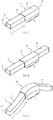
- a hydroforming (IHU) tool 20 includes a first mold half 21 and a second mold half 22, which are arranged to be displaceable relative to each other and are movable substantially perpendicular to a parting plane. Exemplary the dividing plane in the FIGS. 1a to 1e shown vertically, but also horizontal parting planes or a plurality of arbitrarily aligned parting lines is conceivable.
- the first mold half 21 and the second mold half 22 enclose a cavity 23 inside.
- FIG. 1b the hydroforming die 20 is shown in an open position, wherein in the area that later forms the cavity 23, a semi-finished product 11 'is introduced.
- the metallic hollow section 11 is created.
- This semifinished product 11 ' can be, for example, a pipe, a square profile or a profile with an arbitrary cross-sectional area.
- conically tapered ie tapered profiles are conceivable.
- a profile of aluminum or steel is to be used here as the material.
- the tool halves 21, 22 are moved together, so that the cavity 23 is formed, in the interior of which the semifinished product 11' lies, cf. Fig. 1 c.
- the semifinished product 11 'in this case has an inner cavity 18, which is then subjected to a forming pressure P IHU .
- the metallic hollow profile 11 is removed from the hydroforming die 20 by the first mold half 21 and the second mold half 22 are moved apart, as in Figure 1e shown.
- the metallic hollow profile 11 can then be removed from the hydroforming die 20.
- the invention should not be limited to the cross-sectional shape shown here, which is shown as a trapezoid with rounded corners, because according to the invention, any cross-sectional shape can be used, thus also round, triangular, polygonal or combined cross-sectional shapes.
- the metallic hollow section 11 after its production in the hydroforming process has a predetermined cross-sectional shape and a predetermined profile profile.
- the cross-sectional shape along the profile course also vary, so that tapered areas arise substantially in the longitudinal direction L of the profile profile.
- the profile profile can also form undercuts.
- fibers 16, 19 are applied in a predetermined section 13 to a surface 14 of the metallic hollow profile 11, cf. Figure 2a - c .
- fibers 16, 19 are braided, such as in FIG. 3 shown.
- the metallic hollow profile 11 is guided by a braiding device 40, wherein it is braided at the same time with fibers 16, 19.
- These fibers 16, 19 are discharged from fiber memories 41.
- only predetermined portions 13 may be braided or the surface 14 of the metallic hollow profile 11 may be completely braided with fibers 16, 19.
- the provided with fibers 16, 19 metallic hollow section 11 is then inserted according to a first embodiment of the invention in an RTM tool.
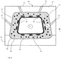
- RTM tool 30 is in FIG. 4 and comprises a lower mold half 31 and an upper mold half 32, which can be apart and moved back substantially perpendicular to the parting plane.
- the two tool halves 31, 32 form a cavity in the contracted state, in which the metallic hollow section 11 is inserted with fibers 16 arranged thereon.
- the upper mold half 32 has feed channels 33, which act as sprues and over which a plastic matrix, in particular resin, can be introduced into the cavity.
- the plastic matrix 17 is conducted in particular as a resin under pressure and temperature in the cavity and penetrates the braided fiber complex.
- the stay threads are shown as circular fibers 16 which extend in the axial direction L, ie substantially parallel to the profile profile.
- the braiding fibers 19 are shown elliptical in the sectional view, since their own longitudinal axis form an angle with the longitudinal direction L of the profile profile.
- the finished component 10 can be removed from the RTM tool 30. Subsequently, edge regions 50 of the casing 12 are finally cut. As in FIG. 4 is shown, an internal pressure P I is built up in the interior of the cavity 18 of the metallic hollow section 11, which counteracts the transfer molding pressure P A during the RTM process. As a result, on the one hand, a higher transfer molding pressure P A can be applied, so that the resin 17 can penetrate the fiber layer with the fibers 16 particularly well and, on the other hand, ensure that no unwanted deformations result on the component.
- the transfer molding pressure P A can be in a range from 1 to 100 bar, preferably about 80 bar.
- a second embodiment which differs from the first embodiment according to the invention differs in that no RTM method is used to form the plastic matrix of the sheath 12, but that it is manufactured in a press process.
- the production of the metallic hollow profile 11 takes place in the hydroforming process.
- at least one prepreg is applied in predetermined regions 13 of the surface 14 of the metallic hollow profile 11.
- These prepregs are fibers, in particular Carbon, aramid or glass fiber, which are pre-impregnated with a plastic matrix or resin or preimpregnated. By applying pressure and / or temperature, the plastic matrix or the resin cures and thus forms the sheath 12.
- the metallic hollow profile 11 is inserted with the arranged prepregs in a pressing tool. Due to the arrangement of the prepregs around the metallic hollow profile 11 around, this is an elastic, substantially tubular tool, which is at least over the area which is surrounded with prepregs slipped. Subsequently, the tubular pressing tool is geometrically contracted. For this purpose, it is optionally possible to generate a negative pressure up to a vacuum in the interior of the pressing tool and / or to apply an overpressure to the outside of the pressing tool. Due to the pressure and the additional application of temperature, the resin of the individual prepregs is melted together, bonded together and cured. Finally, then the finished component comprising a metallic hollow section 11 and a sheath 12, are removed from the press tool. As an alternative to the pressing tool, an autoclave can also be used to produce casing 12 from prepregs.
- thermoplastic to To produce a mesh with a high stability and high material properties.
- thermoplastics are later melted, ie converted into a liquid state, so that they merge together materially to a matrix to form after solidification, the plastic or resin matrix of the sheath 12.
- the metallic hollow section 11 is placed thereon with fiber braid in a pressing tool in which the Fibers with temperature and pressure can be applied.
- a pressing tool has already been explained above in relation to the second embodiment.
- hybrid yarn is used instead of the thermoplastic yarn.
- Such hybrid yarns comprise a monofilament, such as carbon, aramid and / or glass fiber, and a thermoplastic sheath disposed thereon.
- a braid is first produced here, which is then subjected to temperature and / or pressure in a pressing tool or an autoclave. The thermoplastic portions of the hybrid yarn melt, penetrate the mesh, bond cohesively and solidify to the plastic matrix, which forms the plastic matrix of the shell as in the first alternative.
- the metallic hollow profile 11 when it is introduced into the transfer molding tool 30 or each pressing tool, sealed against the tool so that a seal is formed, which prevents resin between the respective tool and the metallic hollow section 11 can swell out.
- openings must be provided in the pressing die, which allow a defined flow of the resin when the prepregs are pressurized.
- the inner cavity 18 of the metallic hollow profile 11 can be subjected to an internal pressure P I. This internal pressure can be in a range of 1300 to 2800 bar, wherein the edge areas are to be included.
Claims (5)
- Procédé d'obtention d'une pièce en matériau hybride (10) comprenant un profilé métallique creux (11) ainsi qu'une enveloppe (12) située sur celui-ci comprenant des étapes consistant à :- fabriquer le profilé métallique creux (11) avec une section de forme prédéfinie et un tracé prédéfini, le profilé métallique creux (11) étant obtenu par la mise en oeuvre d'un procédé de formage haute pression interne,- fabriquer une enveloppe (12) sur au moins un segment (13) de la surface externe (14) du profilé métallique creux (11), cette enveloppe (12) étant réalisée en un matériau synthétique renforcé par des fibres sans fin (16, 19), les fibres sans fin (16, 19) étant en particulier des fibres de carbone, des fibres d'aramide et/ou des fibres de verre, et, après la fabrication du profilé métallique creux (11), les fibres sans fin (16, 19) étant appliquées sur au moins un segment prédéfini (13) de la surface extérieure (14) de ce profilé métallique creux, et le profilé métallique creux (11) étant introduit avec les fibres sans fin (16, 19) appliquées sur celui-ci dans un outil de filage (30), en particulier dans un outil de moulage par transfert de résine, et, au moins dans le segment sur lequel sont situées les fibres (16, 19), une matrice en matériau synthétique (17) en particulier une résine étant appliquée puis la matrice en matériau synthétique (17) moulé étant durcie pour obtenir une pièce moulée,caractérisé en ce que
les fibres sans fin (16, 19) sont appliquées sur le segment prédéfini (13) du profilé métallique creux (11) sous la forme d'une tresse et/ou d'une bobine, et, au moins pendant l'application de la matrice en matériau synthétique (17) on engendre, dans une cavité interne (18) du profilé métallique creux (11), une pression interne (PI) qui s'oppose à la pression de filage externe (PA). - Procédé conforme à la revendication 1,
caractérisé en ce que
au moins l'une des fibres sans fin (16, 18) est réalisée sous la forme d'une fibre d'àme (16), et est essentiellement située dans la direction longitudinale (L) de la pièce métallique hybride (10). - Procédé conforme à l'une des revendications précédentes,
caractérisé en ce que
la pièce métallique hybride (10) est une pièce de structure sollicitée lors d'une collision en particulier pour des véhicules automobiles. - Procédé conforme à la revendication 1,
caractérisé en ce que
le profilé métallique creux (11) équipé de la matrice en matériau synthétique (17) est démoulé de l'outil de filage (30) et est découpé sur les zones de bord (50) de l'enveloppe (12). - Procédé conforme à la revendication 1,
caractérisé en ce qu'
un fluide en particulier à l'état liquide ou à l'état gazeux est introduit dans la cavité interne (18) et est soumis à la pression interne (PI).
Priority Applications (1)
| Application Number | Priority Date | Filing Date | Title |
|---|---|---|---|
| EP17153552.9A EP3178634B1 (fr) | 2010-12-15 | 2011-10-21 | Procédé de fabrication d'un composant en matériau hybride |
Applications Claiming Priority (1)
| Application Number | Priority Date | Filing Date | Title |
|---|---|---|---|
| DE102010063094A DE102010063094A1 (de) | 2010-12-15 | 2010-12-15 | Verfahren zur Herstellung eines materialhybriden Bauteils |
Related Child Applications (2)
| Application Number | Title | Priority Date | Filing Date |
|---|---|---|---|
| EP17153552.9A Division EP3178634B1 (fr) | 2010-12-15 | 2011-10-21 | Procédé de fabrication d'un composant en matériau hybride |
| EP17153552.9A Division-Into EP3178634B1 (fr) | 2010-12-15 | 2011-10-21 | Procédé de fabrication d'un composant en matériau hybride |
Publications (2)
| Publication Number | Publication Date |
|---|---|
| EP2465665A1 EP2465665A1 (fr) | 2012-06-20 |
| EP2465665B1 true EP2465665B1 (fr) | 2017-03-29 |
Family
ID=44946982
Family Applications (2)
| Application Number | Title | Priority Date | Filing Date |
|---|---|---|---|
| EP17153552.9A Active EP3178634B1 (fr) | 2010-12-15 | 2011-10-21 | Procédé de fabrication d'un composant en matériau hybride |
| EP11186121.7A Active EP2465665B1 (fr) | 2010-12-15 | 2011-10-21 | Procédé de fabrication d'un composant en matériau hybride |
Family Applications Before (1)
| Application Number | Title | Priority Date | Filing Date |
|---|---|---|---|
| EP17153552.9A Active EP3178634B1 (fr) | 2010-12-15 | 2011-10-21 | Procédé de fabrication d'un composant en matériau hybride |
Country Status (2)
| Country | Link |
|---|---|
| EP (2) | EP3178634B1 (fr) |
| DE (1) | DE102010063094A1 (fr) |
Families Citing this family (15)
| Publication number | Priority date | Publication date | Assignee | Title |
|---|---|---|---|---|
| DE102011056202B4 (de) * | 2011-12-09 | 2017-11-09 | Thyssenkrupp System Engineering Gmbh | Verfahren zur Herstellung eines Hohlkörperbauteils |
| DE102012021493A1 (de) * | 2012-10-31 | 2014-04-30 | Daimler Ag | Querträgeranordnung und Herstellungsverfahren |
| US9290212B2 (en) | 2013-05-24 | 2016-03-22 | Ford Global Technologies, Llc | Carbon fiber prepreg-wrapped beam structures |
| DE102013106070C5 (de) * | 2013-06-12 | 2019-10-24 | Leichtbau-Zentrum Sachsen Gmbh | Seitenwandgruppe für Personenkraftwagen |
| DE102013214788A1 (de) * | 2013-07-29 | 2015-01-29 | Bayerische Motoren Werke Aktiengesellschaft | Profilbauteil einer Fahrzeugkarosserie |
| DE102013220337A1 (de) | 2013-10-09 | 2015-04-09 | Bayerische Motoren Werke Aktiengesellschaft | Verfahren zum Herstellen eines verstärkten Faserverbundbauteils |
| DE102013221172A1 (de) * | 2013-10-18 | 2015-04-23 | Bayerische Motoren Werke Aktiengesellschaft | Verfahren zum Herstellen eines verstärkten Faserverbundbauteils |
| DE102013021876A1 (de) * | 2013-12-21 | 2015-06-25 | Audi Ag | Verfahren und Vorrichtung zur Herstellung flächiger Verbundstrukturen |
| DE102014217372A1 (de) * | 2014-09-01 | 2016-03-03 | Bayerische Motoren Werke Aktiengesellschaft | Verfahren zum Herstellen eines lokal verstärkten Profilbauteils |
| KR101866080B1 (ko) | 2016-10-31 | 2018-06-11 | 현대자동차주식회사 | 센터필라용 충격 흡수 레인프 구조 |
| DE102017116519A1 (de) * | 2017-07-21 | 2019-01-24 | Innovative Dragon Ltd. | Bauweise und Auslegung von Fahrzeugkarosserien, Chassis und Monocoques |
| DE102018212442A1 (de) * | 2018-07-25 | 2020-01-30 | Brose Fahrzeugteile Gmbh & Co. Kommanditgesellschaft, Coburg | Fahrzeugsitzgestell mit einem aus einem Faserverbundwerkstoff gefertigten Rohrelement |
| US10875265B2 (en) * | 2019-01-08 | 2020-12-29 | Goodrich Corporation | Hybrid metallic/composite arrangement for torque, bending, shear, and axial loading |
| DE102019005910A1 (de) * | 2019-08-22 | 2021-02-25 | Siempelkamp Maschinen- Und Anlagenbau Gmbh | Verfahren und Vorrichtung zum Erzeugen eines Bauelements |
| CN113119502A (zh) * | 2021-04-12 | 2021-07-16 | 长春长光宇航复合材料有限公司 | 一种复合材料曲管及制备方法 |
Citations (4)
| Publication number | Priority date | Publication date | Assignee | Title |
|---|---|---|---|---|
| DE3843488A1 (de) * | 1988-12-23 | 1990-07-05 | Ver Foerderung Inst Kunststoff | Wickelanlage sowie wickelverfahren |
| EP1262374A1 (fr) * | 2001-05-29 | 2002-12-04 | Inalfa Industries B.V. | Elément absorbant l'énergie de choc |
| EP1698410A1 (fr) * | 2005-03-04 | 2006-09-06 | Corus Staal BV | Tube adapté pour l'utilisation dans un procédé d'hydroformage et procédé d'hydroformage d'un tube |
| US20100083815A1 (en) * | 2007-08-10 | 2010-04-08 | Toyota Jidosha Kabushiki Kaisha | Fiber reinforced resin member and method of manufacturing the same, and apparatus manufacturing fiber fabric |
Family Cites Families (10)
| Publication number | Priority date | Publication date | Assignee | Title |
|---|---|---|---|---|
| US3028284A (en) * | 1953-11-24 | 1962-04-03 | John F Reeves | Molding method for plastic bodies |
| IT1205783B (it) * | 1986-04-30 | 1989-03-31 | Dana Corp | Elementi tubolari composti per albero motore di veicoli e metodi per la fabbricazione |
| GB2222653A (en) * | 1988-09-07 | 1990-03-14 | Ti Corporate Services | Hollow tubular structures of fibre reinforced plastics material and method for their production |
| CA2212244C (fr) * | 1995-12-04 | 2007-05-29 | Toray Industries, Inc. | Recipient de pression et procede pour le fabriquer |
| DE19803909A1 (de) * | 1998-02-02 | 1999-08-05 | Ver Foerderung Inst Kunststoff | Verfahren zur Herstellung von endlosfaserverstärkten Hohlkörpern im Harzinjektionsverfahren |
| DE10158627B4 (de) * | 2001-11-29 | 2005-08-25 | Fraunhofer-Gesellschaft zur Förderung der angewandten Forschung e.V. | Trägerstrukturen zur Aufnahme von Kräften und Verformungsenergie |
| EP1762773A1 (fr) * | 2005-09-09 | 2007-03-14 | H.P.O. Helderse Project Ontwikkeling B.V. | Méthode de fabrication d'un réservoir sous pression et réservoir sous pression |
| FR2890591B1 (fr) * | 2005-09-12 | 2012-10-19 | Eads | Procede de fabrication d'une piece composite rtm et piece composite obtenue selon ce procede |
| US7824171B2 (en) * | 2005-10-31 | 2010-11-02 | The Boeing Company | Corner-consolidating inflatable apparatus and method for manufacturing composite structures |
| DE102007027755B4 (de) * | 2007-06-16 | 2019-08-29 | Bayerische Motoren Werke Aktiengesellschaft | Verfahren zur Herstellung eines faserverstärkten Kunststoffbauteils |
-
2010
- 2010-12-15 DE DE102010063094A patent/DE102010063094A1/de not_active Withdrawn
-
2011
- 2011-10-21 EP EP17153552.9A patent/EP3178634B1/fr active Active
- 2011-10-21 EP EP11186121.7A patent/EP2465665B1/fr active Active
Patent Citations (4)
| Publication number | Priority date | Publication date | Assignee | Title |
|---|---|---|---|---|
| DE3843488A1 (de) * | 1988-12-23 | 1990-07-05 | Ver Foerderung Inst Kunststoff | Wickelanlage sowie wickelverfahren |
| EP1262374A1 (fr) * | 2001-05-29 | 2002-12-04 | Inalfa Industries B.V. | Elément absorbant l'énergie de choc |
| EP1698410A1 (fr) * | 2005-03-04 | 2006-09-06 | Corus Staal BV | Tube adapté pour l'utilisation dans un procédé d'hydroformage et procédé d'hydroformage d'un tube |
| US20100083815A1 (en) * | 2007-08-10 | 2010-04-08 | Toyota Jidosha Kabushiki Kaisha | Fiber reinforced resin member and method of manufacturing the same, and apparatus manufacturing fiber fabric |
Non-Patent Citations (2)
| Title |
|---|
| ANONYMOUS: "Innenhochdruckumformen - Wikipedia", WIKIPEDIA, 10 August 2011 (2011-08-10), XP055206338, Retrieved from the Internet <URL:https://de.wikipedia.org/w/index.php?title=Innenhochdruckumformen&oldid=92277367> [retrieved on 20150805] * |
| ANONYMOUS: "Spritzpressen - Wikipedia", WIKIPEDIA, 14 August 2011 (2011-08-14), pages 1 - 4, XP055206335, Retrieved from the Internet <URL:https://de.wikipedia.org/w/index.php?title=Spritzpressen&oldid=92428436> [retrieved on 20150805] * |
Also Published As
| Publication number | Publication date |
|---|---|
| EP3178634B1 (fr) | 2019-07-31 |
| EP3178634A1 (fr) | 2017-06-14 |
| DE102010063094A1 (de) | 2012-06-21 |
| EP2465665A1 (fr) | 2012-06-20 |
Similar Documents
| Publication | Publication Date | Title |
|---|---|---|
| EP2465665B1 (fr) | Procédé de fabrication d'un composant en matériau hybride | |
| EP0561151B1 (fr) | Procédé pour la fabrication de supports en matières synthétiques renforcées de fibres pour pare-choc de véhicules ainsi que supports similaires | |
| DE10210517B3 (de) | Verfahren zur Herstellung eines Bauteiles in Faserverbundbauweise | |
| DE102011120986B4 (de) | Spritzgussverfahren zur Fertigung eines Faserverbund-Hohlprofilbauteils | |
| DE102009060689B4 (de) | Verfahren zur Herstellung eines faserverstärkten Bauteils sowie Vorrichtung zur Durchführung des Verfahrens | |
| EP2524796B1 (fr) | Procédé et installation pour la fabrication d'un élément en matière synthétique essentiellement en forme de coque | |
| EP2227377B1 (fr) | Procédé pour produire un châssis de véhicule à cavités multiples et châssis de vehicule ainsi obtenu | |
| DE102008027429B4 (de) | Verfahren zur Herstellung einer Rohbaustruktur für einen Kraftwagen | |
| DE3113791A1 (de) | "rohrfoermiger hohlkoerper, verfahren zu seiner herstellung sowie vorrichtung zur durchfuehrung des verfahrens" | |
| DE102010056293B4 (de) | Verfahren zum Herstellen eines hohlen Faserverbundbauteils und Formkörper | |
| DE102010033627A1 (de) | Geformtes Kunststoff-Mehrschicht-Bauteil mit endlosverstärkten Faserlagen und Verfahren zu dessen Herstellung | |
| DE102011011577A1 (de) | Verfahren zum Herstellen einer Drehstabfeder oder eines Wankstabilisator | |
| DE102012018801B4 (de) | Beplankungsbauteil für einen Kraftwagen und Verfahren zum Herstellen eines Beplankungsbauteils | |
| EP2489499A1 (fr) | Composant composite en fibres formant une structure porteuse pour un véhicule automobile et procédé de fabrication du composant composite en fibres | |
| DE102012004168A1 (de) | Verfahren zum Spritzgießen von Hohlkörpern mit Endlosfaser-Verstärkungselementen | |
| EP2497624B1 (fr) | Demi-produit en fibre comprenant une âme et procédé de fabrication d'un composant en matière synthétique renforcé par des fibres | |
| DE102011009506B4 (de) | Vorrichtung zur Herstellung hohler Formbauteile aus einem Faserverbundwerkstoff | |
| EP2626218B1 (fr) | Procédé de fabrication d'une jante à base de matière première composite en fibres et jante pour un véhicule automobile | |
| DE102011087497A1 (de) | Verfahren zur Herstellung von Faserverbund-Hohlbauteilen | |
| EP3147112A1 (fr) | Fabrication d'objets ayant une zone renforcee par des fibres | |
| EP3332951B1 (fr) | Noyau éclatable destiné à la fabrication d'un élément structural composite en fibres, utilisation d'un noyau éclatable et procédé de fabrication d'un élément structural composite en fibres | |
| EP3347193B1 (fr) | Procédé de fabrication d'une pièce hybride composite fibre matrice et pièce hybride composite fibre matrice | |
| DE102014208835A1 (de) | Verfahren zur Herstellung eines Kunststoffbauteils | |
| DE102009053947A1 (de) | Verfahren zum Herstellen von Bauteilen | |
| EP3778179A1 (fr) | Procédé et dispositif de fabrication d'un composant |
Legal Events
| Date | Code | Title | Description |
|---|---|---|---|
| PUAI | Public reference made under article 153(3) epc to a published international application that has entered the european phase |
Free format text: ORIGINAL CODE: 0009012 |
|
| AK | Designated contracting states |
Kind code of ref document: A1 Designated state(s): AL AT BE BG CH CY CZ DE DK EE ES FI FR GB GR HR HU IE IS IT LI LT LU LV MC MK MT NL NO PL PT RO RS SE SI SK SM TR |
|
| AX | Request for extension of the european patent |
Extension state: BA ME |
|
| 17P | Request for examination filed |
Effective date: 20120809 |
|
| 17Q | First examination report despatched |
Effective date: 20130405 |
|
| RAP1 | Party data changed (applicant data changed or rights of an application transferred) |
Owner name: BAYERISCHE MOTOREN WERKE AKTIENGESELLSCHAFT |
|
| GRAP | Despatch of communication of intention to grant a patent |
Free format text: ORIGINAL CODE: EPIDOSNIGR1 |
|
| RIC1 | Information provided on ipc code assigned before grant |
Ipc: B29C 63/24 20060101AFI20161011BHEP Ipc: B62D 29/00 20060101ALI20161011BHEP Ipc: B29C 70/86 20060101ALI20161011BHEP Ipc: B29K 105/08 20060101ALN20161011BHEP Ipc: B29C 53/58 20060101ALN20161011BHEP Ipc: B29C 70/08 20060101ALI20161011BHEP |
|
| RIC1 | Information provided on ipc code assigned before grant |
Ipc: B29C 70/86 20060101ALI20161024BHEP Ipc: B62D 29/00 20060101ALI20161024BHEP Ipc: B29C 63/24 20060101AFI20161024BHEP Ipc: B29K 105/08 20060101ALN20161024BHEP Ipc: B29C 70/08 20060101ALI20161024BHEP Ipc: B29C 53/58 20060101ALN20161024BHEP |
|
| INTG | Intention to grant announced |
Effective date: 20161109 |
|
| GRAS | Grant fee paid |
Free format text: ORIGINAL CODE: EPIDOSNIGR3 |
|
| GRAA | (expected) grant |
Free format text: ORIGINAL CODE: 0009210 |
|
| AK | Designated contracting states |
Kind code of ref document: B1 Designated state(s): AL AT BE BG CH CY CZ DE DK EE ES FI FR GB GR HR HU IE IS IT LI LT LU LV MC MK MT NL NO PL PT RO RS SE SI SK SM TR |
|
| REG | Reference to a national code |
Ref country code: GB Ref legal event code: FG4D Free format text: NOT ENGLISH |
|
| REG | Reference to a national code |
Ref country code: CH Ref legal event code: EP |
|
| REG | Reference to a national code |
Ref country code: AT Ref legal event code: REF Ref document number: 879322 Country of ref document: AT Kind code of ref document: T Effective date: 20170415 |
|
| REG | Reference to a national code |
Ref country code: IE Ref legal event code: FG4D Free format text: LANGUAGE OF EP DOCUMENT: GERMAN |
|
| REG | Reference to a national code |
Ref country code: DE Ref legal event code: R096 Ref document number: 502011011932 Country of ref document: DE |
|
| PG25 | Lapsed in a contracting state [announced via postgrant information from national office to epo] |
Ref country code: GR Free format text: LAPSE BECAUSE OF FAILURE TO SUBMIT A TRANSLATION OF THE DESCRIPTION OR TO PAY THE FEE WITHIN THE PRESCRIBED TIME-LIMIT Effective date: 20170630 Ref country code: HR Free format text: LAPSE BECAUSE OF FAILURE TO SUBMIT A TRANSLATION OF THE DESCRIPTION OR TO PAY THE FEE WITHIN THE PRESCRIBED TIME-LIMIT Effective date: 20170329 Ref country code: FI Free format text: LAPSE BECAUSE OF FAILURE TO SUBMIT A TRANSLATION OF THE DESCRIPTION OR TO PAY THE FEE WITHIN THE PRESCRIBED TIME-LIMIT Effective date: 20170329 Ref country code: NO Free format text: LAPSE BECAUSE OF FAILURE TO SUBMIT A TRANSLATION OF THE DESCRIPTION OR TO PAY THE FEE WITHIN THE PRESCRIBED TIME-LIMIT Effective date: 20170629 Ref country code: LT Free format text: LAPSE BECAUSE OF FAILURE TO SUBMIT A TRANSLATION OF THE DESCRIPTION OR TO PAY THE FEE WITHIN THE PRESCRIBED TIME-LIMIT Effective date: 20170329 |
|
| REG | Reference to a national code |
Ref country code: NL Ref legal event code: MP Effective date: 20170329 |
|
| PG25 | Lapsed in a contracting state [announced via postgrant information from national office to epo] |
Ref country code: LV Free format text: LAPSE BECAUSE OF FAILURE TO SUBMIT A TRANSLATION OF THE DESCRIPTION OR TO PAY THE FEE WITHIN THE PRESCRIBED TIME-LIMIT Effective date: 20170329 Ref country code: BG Free format text: LAPSE BECAUSE OF FAILURE TO SUBMIT A TRANSLATION OF THE DESCRIPTION OR TO PAY THE FEE WITHIN THE PRESCRIBED TIME-LIMIT Effective date: 20170629 Ref country code: RS Free format text: LAPSE BECAUSE OF FAILURE TO SUBMIT A TRANSLATION OF THE DESCRIPTION OR TO PAY THE FEE WITHIN THE PRESCRIBED TIME-LIMIT Effective date: 20170329 Ref country code: SE Free format text: LAPSE BECAUSE OF FAILURE TO SUBMIT A TRANSLATION OF THE DESCRIPTION OR TO PAY THE FEE WITHIN THE PRESCRIBED TIME-LIMIT Effective date: 20170329 |
|
| PG25 | Lapsed in a contracting state [announced via postgrant information from national office to epo] |
Ref country code: NL Free format text: LAPSE BECAUSE OF FAILURE TO SUBMIT A TRANSLATION OF THE DESCRIPTION OR TO PAY THE FEE WITHIN THE PRESCRIBED TIME-LIMIT Effective date: 20170329 |
|
| REG | Reference to a national code |
Ref country code: FR Ref legal event code: PLFP Year of fee payment: 7 |
|
| PG25 | Lapsed in a contracting state [announced via postgrant information from national office to epo] |
Ref country code: SK Free format text: LAPSE BECAUSE OF FAILURE TO SUBMIT A TRANSLATION OF THE DESCRIPTION OR TO PAY THE FEE WITHIN THE PRESCRIBED TIME-LIMIT Effective date: 20170329 Ref country code: EE Free format text: LAPSE BECAUSE OF FAILURE TO SUBMIT A TRANSLATION OF THE DESCRIPTION OR TO PAY THE FEE WITHIN THE PRESCRIBED TIME-LIMIT Effective date: 20170329 Ref country code: RO Free format text: LAPSE BECAUSE OF FAILURE TO SUBMIT A TRANSLATION OF THE DESCRIPTION OR TO PAY THE FEE WITHIN THE PRESCRIBED TIME-LIMIT Effective date: 20170329 Ref country code: CZ Free format text: LAPSE BECAUSE OF FAILURE TO SUBMIT A TRANSLATION OF THE DESCRIPTION OR TO PAY THE FEE WITHIN THE PRESCRIBED TIME-LIMIT Effective date: 20170329 Ref country code: ES Free format text: LAPSE BECAUSE OF FAILURE TO SUBMIT A TRANSLATION OF THE DESCRIPTION OR TO PAY THE FEE WITHIN THE PRESCRIBED TIME-LIMIT Effective date: 20170329 |
|
| PG25 | Lapsed in a contracting state [announced via postgrant information from national office to epo] |
Ref country code: PL Free format text: LAPSE BECAUSE OF FAILURE TO SUBMIT A TRANSLATION OF THE DESCRIPTION OR TO PAY THE FEE WITHIN THE PRESCRIBED TIME-LIMIT Effective date: 20170329 Ref country code: SM Free format text: LAPSE BECAUSE OF FAILURE TO SUBMIT A TRANSLATION OF THE DESCRIPTION OR TO PAY THE FEE WITHIN THE PRESCRIBED TIME-LIMIT Effective date: 20170329 Ref country code: IS Free format text: LAPSE BECAUSE OF FAILURE TO SUBMIT A TRANSLATION OF THE DESCRIPTION OR TO PAY THE FEE WITHIN THE PRESCRIBED TIME-LIMIT Effective date: 20170729 Ref country code: PT Free format text: LAPSE BECAUSE OF FAILURE TO SUBMIT A TRANSLATION OF THE DESCRIPTION OR TO PAY THE FEE WITHIN THE PRESCRIBED TIME-LIMIT Effective date: 20170731 |
|
| REG | Reference to a national code |
Ref country code: DE Ref legal event code: R097 Ref document number: 502011011932 Country of ref document: DE |
|
| PG25 | Lapsed in a contracting state [announced via postgrant information from national office to epo] |
Ref country code: DK Free format text: LAPSE BECAUSE OF FAILURE TO SUBMIT A TRANSLATION OF THE DESCRIPTION OR TO PAY THE FEE WITHIN THE PRESCRIBED TIME-LIMIT Effective date: 20170329 |
|
| PLBE | No opposition filed within time limit |
Free format text: ORIGINAL CODE: 0009261 |
|
| STAA | Information on the status of an ep patent application or granted ep patent |
Free format text: STATUS: NO OPPOSITION FILED WITHIN TIME LIMIT |
|
| 26N | No opposition filed |
Effective date: 20180103 |
|
| PG25 | Lapsed in a contracting state [announced via postgrant information from national office to epo] |
Ref country code: SI Free format text: LAPSE BECAUSE OF FAILURE TO SUBMIT A TRANSLATION OF THE DESCRIPTION OR TO PAY THE FEE WITHIN THE PRESCRIBED TIME-LIMIT Effective date: 20170329 Ref country code: MC Free format text: LAPSE BECAUSE OF FAILURE TO SUBMIT A TRANSLATION OF THE DESCRIPTION OR TO PAY THE FEE WITHIN THE PRESCRIBED TIME-LIMIT Effective date: 20170329 |
|
| REG | Reference to a national code |
Ref country code: CH Ref legal event code: PL |
|
| REG | Reference to a national code |
Ref country code: IE Ref legal event code: MM4A |
|
| PG25 | Lapsed in a contracting state [announced via postgrant information from national office to epo] |
Ref country code: LU Free format text: LAPSE BECAUSE OF NON-PAYMENT OF DUE FEES Effective date: 20171021 Ref country code: LI Free format text: LAPSE BECAUSE OF NON-PAYMENT OF DUE FEES Effective date: 20171031 Ref country code: CH Free format text: LAPSE BECAUSE OF NON-PAYMENT OF DUE FEES Effective date: 20171031 |
|
| REG | Reference to a national code |
Ref country code: BE Ref legal event code: MM Effective date: 20171031 |
|
| PG25 | Lapsed in a contracting state [announced via postgrant information from national office to epo] |
Ref country code: BE Free format text: LAPSE BECAUSE OF NON-PAYMENT OF DUE FEES Effective date: 20171031 |
|
| PG25 | Lapsed in a contracting state [announced via postgrant information from national office to epo] |
Ref country code: MT Free format text: LAPSE BECAUSE OF FAILURE TO SUBMIT A TRANSLATION OF THE DESCRIPTION OR TO PAY THE FEE WITHIN THE PRESCRIBED TIME-LIMIT Effective date: 20170329 |
|
| REG | Reference to a national code |
Ref country code: FR Ref legal event code: PLFP Year of fee payment: 8 |
|
| PG25 | Lapsed in a contracting state [announced via postgrant information from national office to epo] |
Ref country code: IE Free format text: LAPSE BECAUSE OF NON-PAYMENT OF DUE FEES Effective date: 20171021 |
|
| REG | Reference to a national code |
Ref country code: AT Ref legal event code: MM01 Ref document number: 879322 Country of ref document: AT Kind code of ref document: T Effective date: 20171021 |
|
| PG25 | Lapsed in a contracting state [announced via postgrant information from national office to epo] |
Ref country code: AT Free format text: LAPSE BECAUSE OF NON-PAYMENT OF DUE FEES Effective date: 20171021 |
|
| PG25 | Lapsed in a contracting state [announced via postgrant information from national office to epo] |
Ref country code: HU Free format text: LAPSE BECAUSE OF FAILURE TO SUBMIT A TRANSLATION OF THE DESCRIPTION OR TO PAY THE FEE WITHIN THE PRESCRIBED TIME-LIMIT; INVALID AB INITIO Effective date: 20111021 |
|
| PG25 | Lapsed in a contracting state [announced via postgrant information from national office to epo] |
Ref country code: CY Free format text: LAPSE BECAUSE OF NON-PAYMENT OF DUE FEES Effective date: 20170329 |
|
| PG25 | Lapsed in a contracting state [announced via postgrant information from national office to epo] |
Ref country code: MK Free format text: LAPSE BECAUSE OF FAILURE TO SUBMIT A TRANSLATION OF THE DESCRIPTION OR TO PAY THE FEE WITHIN THE PRESCRIBED TIME-LIMIT Effective date: 20170329 |
|
| PG25 | Lapsed in a contracting state [announced via postgrant information from national office to epo] |
Ref country code: TR Free format text: LAPSE BECAUSE OF FAILURE TO SUBMIT A TRANSLATION OF THE DESCRIPTION OR TO PAY THE FEE WITHIN THE PRESCRIBED TIME-LIMIT Effective date: 20170329 |
|
| PG25 | Lapsed in a contracting state [announced via postgrant information from national office to epo] |
Ref country code: AL Free format text: LAPSE BECAUSE OF FAILURE TO SUBMIT A TRANSLATION OF THE DESCRIPTION OR TO PAY THE FEE WITHIN THE PRESCRIBED TIME-LIMIT Effective date: 20170329 |
|
| P01 | Opt-out of the competence of the unified patent court (upc) registered |
Effective date: 20230502 |
|
| PGFP | Annual fee paid to national office [announced via postgrant information from national office to epo] |
Ref country code: GB Payment date: 20231025 Year of fee payment: 13 |
|
| PGFP | Annual fee paid to national office [announced via postgrant information from national office to epo] |
Ref country code: IT Payment date: 20231031 Year of fee payment: 13 Ref country code: FR Payment date: 20231023 Year of fee payment: 13 Ref country code: DE Payment date: 20231017 Year of fee payment: 13 |