EP3218170B1 - Élément structural en matériau renforcé par des fibres et son procédé de fabrication - Google Patents
Élément structural en matériau renforcé par des fibres et son procédé de fabrication Download PDFInfo
- Publication number
- EP3218170B1 EP3218170B1 EP15775722.0A EP15775722A EP3218170B1 EP 3218170 B1 EP3218170 B1 EP 3218170B1 EP 15775722 A EP15775722 A EP 15775722A EP 3218170 B1 EP3218170 B1 EP 3218170B1
- Authority
- EP
- European Patent Office
- Prior art keywords
- fibre
- bundles
- composite material
- material component
- profile
- Prior art date
- Legal status (The legal status is an assumption and is not a legal conclusion. Google has not performed a legal analysis and makes no representation as to the accuracy of the status listed.)
- Active
Links
- 239000000835 fiber Substances 0.000 title claims description 262
- 239000002131 composite material Substances 0.000 title claims description 67
- 238000004519 manufacturing process Methods 0.000 title claims description 26
- 238000001746 injection moulding Methods 0.000 claims description 39
- 239000000463 material Substances 0.000 claims description 31
- 238000000034 method Methods 0.000 claims description 16
- 229920001169 thermoplastic Polymers 0.000 claims description 16
- 239000004416 thermosoftening plastic Substances 0.000 claims description 16
- 229920001187 thermosetting polymer Polymers 0.000 claims description 15
- 239000011159 matrix material Substances 0.000 claims description 12
- 238000002347 injection Methods 0.000 claims description 10
- 239000007924 injection Substances 0.000 claims description 10
- 239000012530 fluid Substances 0.000 claims description 9
- XLYOFNOQVPJJNP-UHFFFAOYSA-N water Substances O XLYOFNOQVPJJNP-UHFFFAOYSA-N 0.000 claims description 9
- 230000001788 irregular Effects 0.000 claims description 5
- 238000010276 construction Methods 0.000 description 11
- 239000007789 gas Substances 0.000 description 10
- 238000005452 bending Methods 0.000 description 8
- 239000000155 melt Substances 0.000 description 6
- 239000002699 waste material Substances 0.000 description 6
- 230000035508 accumulation Effects 0.000 description 5
- 238000009825 accumulation Methods 0.000 description 5
- 238000005516 engineering process Methods 0.000 description 4
- 239000012815 thermoplastic material Substances 0.000 description 4
- 230000015572 biosynthetic process Effects 0.000 description 3
- 239000004744 fabric Substances 0.000 description 3
- 238000000465 moulding Methods 0.000 description 3
- IJGRMHOSHXDMSA-UHFFFAOYSA-N Atomic nitrogen Chemical compound N#N IJGRMHOSHXDMSA-UHFFFAOYSA-N 0.000 description 2
- 229920000049 Carbon (fiber) Polymers 0.000 description 2
- 238000007664 blowing Methods 0.000 description 2
- 239000004917 carbon fiber Substances 0.000 description 2
- 238000007765 extrusion coating Methods 0.000 description 2
- 239000003365 glass fiber Substances 0.000 description 2
- 239000007788 liquid Substances 0.000 description 2
- 229920002430 Fibre-reinforced plastic Polymers 0.000 description 1
- 230000001154 acute effect Effects 0.000 description 1
- 238000004132 cross linking Methods 0.000 description 1
- 230000000694 effects Effects 0.000 description 1
- 239000011151 fibre-reinforced plastic Substances 0.000 description 1
- 239000002657 fibrous material Substances 0.000 description 1
- 239000000945 filler Substances 0.000 description 1
- 239000011261 inert gas Substances 0.000 description 1
- 238000003780 insertion Methods 0.000 description 1
- 230000037431 insertion Effects 0.000 description 1
- 229910052757 nitrogen Inorganic materials 0.000 description 1
- 239000002861 polymer material Substances 0.000 description 1
- 230000002787 reinforcement Effects 0.000 description 1
- 229920006395 saturated elastomer Polymers 0.000 description 1
- 238000007493 shaping process Methods 0.000 description 1
- 239000004753 textile Substances 0.000 description 1
Images


Classifications
-
- B—PERFORMING OPERATIONS; TRANSPORTING
- B29—WORKING OF PLASTICS; WORKING OF SUBSTANCES IN A PLASTIC STATE IN GENERAL
- B29C—SHAPING OR JOINING OF PLASTICS; SHAPING OF MATERIAL IN A PLASTIC STATE, NOT OTHERWISE PROVIDED FOR; AFTER-TREATMENT OF THE SHAPED PRODUCTS, e.g. REPAIRING
- B29C70/00—Shaping composites, i.e. plastics material comprising reinforcements, fillers or preformed parts, e.g. inserts
- B29C70/04—Shaping composites, i.e. plastics material comprising reinforcements, fillers or preformed parts, e.g. inserts comprising reinforcements only, e.g. self-reinforcing plastics
- B29C70/06—Fibrous reinforcements only
- B29C70/10—Fibrous reinforcements only characterised by the structure of fibrous reinforcements, e.g. hollow fibres
- B29C70/16—Fibrous reinforcements only characterised by the structure of fibrous reinforcements, e.g. hollow fibres using fibres of substantial or continuous length
- B29C70/20—Fibrous reinforcements only characterised by the structure of fibrous reinforcements, e.g. hollow fibres using fibres of substantial or continuous length oriented in a single direction, e.g. roofing or other parallel fibres
- B29C70/205—Fibrous reinforcements only characterised by the structure of fibrous reinforcements, e.g. hollow fibres using fibres of substantial or continuous length oriented in a single direction, e.g. roofing or other parallel fibres the structure being shaped to form a three-dimensional configuration
- B29C70/207—Fibrous reinforcements only characterised by the structure of fibrous reinforcements, e.g. hollow fibres using fibres of substantial or continuous length oriented in a single direction, e.g. roofing or other parallel fibres the structure being shaped to form a three-dimensional configuration arranged in parallel planes of fibres crossing at substantial angles
-
- B—PERFORMING OPERATIONS; TRANSPORTING
- B29—WORKING OF PLASTICS; WORKING OF SUBSTANCES IN A PLASTIC STATE IN GENERAL
- B29C—SHAPING OR JOINING OF PLASTICS; SHAPING OF MATERIAL IN A PLASTIC STATE, NOT OTHERWISE PROVIDED FOR; AFTER-TREATMENT OF THE SHAPED PRODUCTS, e.g. REPAIRING
- B29C45/00—Injection moulding, i.e. forcing the required volume of moulding material through a nozzle into a closed mould; Apparatus therefor
- B29C45/14—Injection moulding, i.e. forcing the required volume of moulding material through a nozzle into a closed mould; Apparatus therefor incorporating preformed parts or layers, e.g. injection moulding around inserts or for coating articles
- B29C45/14065—Positioning or centering articles in the mould
-
- B—PERFORMING OPERATIONS; TRANSPORTING
- B29—WORKING OF PLASTICS; WORKING OF SUBSTANCES IN A PLASTIC STATE IN GENERAL
- B29C—SHAPING OR JOINING OF PLASTICS; SHAPING OF MATERIAL IN A PLASTIC STATE, NOT OTHERWISE PROVIDED FOR; AFTER-TREATMENT OF THE SHAPED PRODUCTS, e.g. REPAIRING
- B29C45/00—Injection moulding, i.e. forcing the required volume of moulding material through a nozzle into a closed mould; Apparatus therefor
- B29C45/14—Injection moulding, i.e. forcing the required volume of moulding material through a nozzle into a closed mould; Apparatus therefor incorporating preformed parts or layers, e.g. injection moulding around inserts or for coating articles
- B29C45/14467—Joining articles or parts of a single article
-
- B—PERFORMING OPERATIONS; TRANSPORTING
- B29—WORKING OF PLASTICS; WORKING OF SUBSTANCES IN A PLASTIC STATE IN GENERAL
- B29C—SHAPING OR JOINING OF PLASTICS; SHAPING OF MATERIAL IN A PLASTIC STATE, NOT OTHERWISE PROVIDED FOR; AFTER-TREATMENT OF THE SHAPED PRODUCTS, e.g. REPAIRING
- B29C45/00—Injection moulding, i.e. forcing the required volume of moulding material through a nozzle into a closed mould; Apparatus therefor
- B29C45/14—Injection moulding, i.e. forcing the required volume of moulding material through a nozzle into a closed mould; Apparatus therefor incorporating preformed parts or layers, e.g. injection moulding around inserts or for coating articles
- B29C45/14778—Injection moulding, i.e. forcing the required volume of moulding material through a nozzle into a closed mould; Apparatus therefor incorporating preformed parts or layers, e.g. injection moulding around inserts or for coating articles the article consisting of a material with particular properties, e.g. porous, brittle
- B29C45/14786—Fibrous material or fibre containing material, e.g. fibre mats or fibre reinforced material
-
- B—PERFORMING OPERATIONS; TRANSPORTING
- B29—WORKING OF PLASTICS; WORKING OF SUBSTANCES IN A PLASTIC STATE IN GENERAL
- B29C—SHAPING OR JOINING OF PLASTICS; SHAPING OF MATERIAL IN A PLASTIC STATE, NOT OTHERWISE PROVIDED FOR; AFTER-TREATMENT OF THE SHAPED PRODUCTS, e.g. REPAIRING
- B29C45/00—Injection moulding, i.e. forcing the required volume of moulding material through a nozzle into a closed mould; Apparatus therefor
- B29C45/17—Component parts, details or accessories; Auxiliary operations
- B29C45/1703—Introducing an auxiliary fluid into the mould
- B29C45/1704—Introducing an auxiliary fluid into the mould the fluid being introduced into the interior of the injected material which is still in a molten state, e.g. for producing hollow articles
- B29C45/1706—Introducing an auxiliary fluid into the mould the fluid being introduced into the interior of the injected material which is still in a molten state, e.g. for producing hollow articles using particular fluids or fluid generating substances
-
- B—PERFORMING OPERATIONS; TRANSPORTING
- B29—WORKING OF PLASTICS; WORKING OF SUBSTANCES IN A PLASTIC STATE IN GENERAL
- B29C—SHAPING OR JOINING OF PLASTICS; SHAPING OF MATERIAL IN A PLASTIC STATE, NOT OTHERWISE PROVIDED FOR; AFTER-TREATMENT OF THE SHAPED PRODUCTS, e.g. REPAIRING
- B29C70/00—Shaping composites, i.e. plastics material comprising reinforcements, fillers or preformed parts, e.g. inserts
- B29C70/04—Shaping composites, i.e. plastics material comprising reinforcements, fillers or preformed parts, e.g. inserts comprising reinforcements only, e.g. self-reinforcing plastics
- B29C70/06—Fibrous reinforcements only
- B29C70/10—Fibrous reinforcements only characterised by the structure of fibrous reinforcements, e.g. hollow fibres
- B29C70/16—Fibrous reinforcements only characterised by the structure of fibrous reinforcements, e.g. hollow fibres using fibres of substantial or continuous length
- B29C70/24—Fibrous reinforcements only characterised by the structure of fibrous reinforcements, e.g. hollow fibres using fibres of substantial or continuous length oriented in at least three directions forming a three dimensional structure
-
- B—PERFORMING OPERATIONS; TRANSPORTING
- B29—WORKING OF PLASTICS; WORKING OF SUBSTANCES IN A PLASTIC STATE IN GENERAL
- B29C—SHAPING OR JOINING OF PLASTICS; SHAPING OF MATERIAL IN A PLASTIC STATE, NOT OTHERWISE PROVIDED FOR; AFTER-TREATMENT OF THE SHAPED PRODUCTS, e.g. REPAIRING
- B29C70/00—Shaping composites, i.e. plastics material comprising reinforcements, fillers or preformed parts, e.g. inserts
- B29C70/04—Shaping composites, i.e. plastics material comprising reinforcements, fillers or preformed parts, e.g. inserts comprising reinforcements only, e.g. self-reinforcing plastics
- B29C70/28—Shaping operations therefor
- B29C70/40—Shaping or impregnating by compression not applied
- B29C70/42—Shaping or impregnating by compression not applied for producing articles of definite length, i.e. discrete articles
- B29C70/46—Shaping or impregnating by compression not applied for producing articles of definite length, i.e. discrete articles using matched moulds, e.g. for deforming sheet moulding compounds [SMC] or prepregs
-
- B—PERFORMING OPERATIONS; TRANSPORTING
- B62—LAND VEHICLES FOR TRAVELLING OTHERWISE THAN ON RAILS
- B62D—MOTOR VEHICLES; TRAILERS
- B62D29/00—Superstructures, understructures, or sub-units thereof, characterised by the material thereof
- B62D29/04—Superstructures, understructures, or sub-units thereof, characterised by the material thereof predominantly of synthetic material
- B62D29/043—Superstructures
-
- B—PERFORMING OPERATIONS; TRANSPORTING
- B29—WORKING OF PLASTICS; WORKING OF SUBSTANCES IN A PLASTIC STATE IN GENERAL
- B29C—SHAPING OR JOINING OF PLASTICS; SHAPING OF MATERIAL IN A PLASTIC STATE, NOT OTHERWISE PROVIDED FOR; AFTER-TREATMENT OF THE SHAPED PRODUCTS, e.g. REPAIRING
- B29C45/00—Injection moulding, i.e. forcing the required volume of moulding material through a nozzle into a closed mould; Apparatus therefor
- B29C45/14—Injection moulding, i.e. forcing the required volume of moulding material through a nozzle into a closed mould; Apparatus therefor incorporating preformed parts or layers, e.g. injection moulding around inserts or for coating articles
- B29C45/14065—Positioning or centering articles in the mould
- B29C2045/14131—Positioning or centering articles in the mould using positioning or centering means forming part of the insert
-
- B—PERFORMING OPERATIONS; TRANSPORTING
- B29—WORKING OF PLASTICS; WORKING OF SUBSTANCES IN A PLASTIC STATE IN GENERAL
- B29C—SHAPING OR JOINING OF PLASTICS; SHAPING OF MATERIAL IN A PLASTIC STATE, NOT OTHERWISE PROVIDED FOR; AFTER-TREATMENT OF THE SHAPED PRODUCTS, e.g. REPAIRING
- B29C45/00—Injection moulding, i.e. forcing the required volume of moulding material through a nozzle into a closed mould; Apparatus therefor
- B29C45/17—Component parts, details or accessories; Auxiliary operations
- B29C45/1703—Introducing an auxiliary fluid into the mould
- B29C45/1704—Introducing an auxiliary fluid into the mould the fluid being introduced into the interior of the injected material which is still in a molten state, e.g. for producing hollow articles
- B29C45/1706—Introducing an auxiliary fluid into the mould the fluid being introduced into the interior of the injected material which is still in a molten state, e.g. for producing hollow articles using particular fluids or fluid generating substances
- B29C2045/1707—Introducing an auxiliary fluid into the mould the fluid being introduced into the interior of the injected material which is still in a molten state, e.g. for producing hollow articles using particular fluids or fluid generating substances using a liquid, e.g. water
-
- B—PERFORMING OPERATIONS; TRANSPORTING
- B29—WORKING OF PLASTICS; WORKING OF SUBSTANCES IN A PLASTIC STATE IN GENERAL
- B29L—INDEXING SCHEME ASSOCIATED WITH SUBCLASS B29C, RELATING TO PARTICULAR ARTICLES
- B29L2024/00—Articles with hollow walls
-
- B—PERFORMING OPERATIONS; TRANSPORTING
- B29—WORKING OF PLASTICS; WORKING OF SUBSTANCES IN A PLASTIC STATE IN GENERAL
- B29L—INDEXING SCHEME ASSOCIATED WITH SUBCLASS B29C, RELATING TO PARTICULAR ARTICLES
- B29L2031/00—Other particular articles
- B29L2031/001—Profiled members, e.g. beams, sections
-
- B—PERFORMING OPERATIONS; TRANSPORTING
- B29—WORKING OF PLASTICS; WORKING OF SUBSTANCES IN A PLASTIC STATE IN GENERAL
- B29L—INDEXING SCHEME ASSOCIATED WITH SUBCLASS B29C, RELATING TO PARTICULAR ARTICLES
- B29L2031/00—Other particular articles
- B29L2031/30—Vehicles, e.g. ships or aircraft, or body parts thereof
-
- B—PERFORMING OPERATIONS; TRANSPORTING
- B29—WORKING OF PLASTICS; WORKING OF SUBSTANCES IN A PLASTIC STATE IN GENERAL
- B29L—INDEXING SCHEME ASSOCIATED WITH SUBCLASS B29C, RELATING TO PARTICULAR ARTICLES
- B29L2031/00—Other particular articles
- B29L2031/737—Articles provided with holes, e.g. grids, sieves
-
- Y—GENERAL TAGGING OF NEW TECHNOLOGICAL DEVELOPMENTS; GENERAL TAGGING OF CROSS-SECTIONAL TECHNOLOGIES SPANNING OVER SEVERAL SECTIONS OF THE IPC; TECHNICAL SUBJECTS COVERED BY FORMER USPC CROSS-REFERENCE ART COLLECTIONS [XRACs] AND DIGESTS
- Y10—TECHNICAL SUBJECTS COVERED BY FORMER USPC
- Y10T—TECHNICAL SUBJECTS COVERED BY FORMER US CLASSIFICATION
- Y10T428/00—Stock material or miscellaneous articles
- Y10T428/24—Structurally defined web or sheet [e.g., overall dimension, etc.]
- Y10T428/24058—Structurally defined web or sheet [e.g., overall dimension, etc.] including grain, strips, or filamentary elements in respective layers or components in angular relation
Definitions
- the present invention relates to a fiber composite component and a method for producing a fiber composite component.
- thermoplastic material It is known from the prior art that fiber bundles and / or scrims and / or fabrics pre-soaked with thermoplastic material are arranged in a planar manner in order to build up components. It is also known that individual points of fiber-reinforced plastic are overmolded with thermoplastic material with and without fibers. These methods serve to reinforce places with higher loads, in particular places where force is introduced, and thus increase the stability of the component.
- a textile fiber material such as, for example, scrim, fabric, knitted fabric, bundle or the like
- thermoplastic material such as, for example, thermoplastic material with and without fibers.
- Shells or hollow components with a closed surface or the like are produced from the aforementioned method.
- the DE 10 2006 040 748 A1 discloses, for example, an injection molding process for fiber-reinforced motor vehicle parts made from fiber-reinforced thermoplastics by injection molding.
- a fiber composite material component is shown, which is formed from fiber-reinforced thermoplastic material with integrated components reinforced with continuous fibers.
- a fiber composite component with the features of claim 1.
- a fiber composite component has fiber bundles and a matrix of thermoplastic and / or thermosetting material, the fiber bundles being arranged in such a way that they form a profile, one fiber bundle each with the matrix in the profile forms a strut which is part of the profile, strut means being arranged between the fiber bundles, at least two fiber bundles being arranged skewed to each other, the course of at least two fiber bundles crossing, with at least the two crooked and crossing Fiber bundles are embedded in the matrix in the area of their intersection in such a way that the struts formed by the two skewed fiber bundles each have a widening in this area, with at least one opening being provided in the area of the widening and the opening ung is connected to a cavity which is formed in the widening.
- the invention is based on the basic idea, by means of at least one cavity in the area of the intersection of the two skewed fiber bundles To avoid accumulations of material.
- the use of skewed fiber bundles allows the structure of the fiber composite component to be provided with nodes or crossings. These nodes or crossings stiffen the profile of the fiber composite component. As a result, a very stiff fiber composite component can be produced with a comparatively low weight, which component can be used, for example, as a body component.
- the fiber composite material component according to the invention has the particular advantage that overall it can be built more easily than known from the prior art, moreover, a three-dimensional arrangement of continuous fibers is possible and a fiber layer that is more suitable for the load can be provided. This further achieves the fact that the use of material can advantageously be reduced and there is less waste.
- the opening is connected to the cavity, there is the advantage that the cavity becomes accessible through the opening and, for example, the opening and the cavity can be used for receiving a fastening element such as a bolt or a screw. It is conceivable that several openings are provided which are connected to the cavity. These openings can be used, for example, in connection with the formation of the cavity by internal pressure injection molding (see also below), to blow out melt from the cavity.
- struts advantageously makes it possible to direct the loads in the profile and to achieve a comparatively high level of stability despite the lightweight construction.
- the struts can in particular absorb tensile stresses and / or bending stresses.
- the fiber composite component can have at least two or more profiles, with at least two fiber bundles per profile being arranged skewed and crossing one another and with at least one cavity being formed in the area of the intersection of the skewed fiber bundles.
- the skewed and intersecting fiber bundles can be arranged perpendicular to one another. As a result, a stable, truss-like structure can easily be provided in the profile.
- At least one fiber bundle is a UD fiber bundle comprising several unidirectionally arranged fibers.
- UD fiber bundles are bundles comprising several unidirectional fibers, i.e. also fiber bundles that do not have any twisting of the fibers.
- the fibers can be, for example, carbon fibers. It is also conceivable that the fibers are glass fibers. In principle, however, fibers made from another suitable material can also be selected.
- At least one fiber bundle consists exclusively of unidirectionally arranged fibers in the direction of the course of the fiber bundles. This enables a simple construction of the fiber composite material component.
- At least one fiber bundle has first unidirectionally arranged fibers in the direction of the course of the fiber bundles and second unidirectionally arranged fibers with which the first fibers are braided. This can improve the stability of the fiber bundle.
- At least one fiber bundle is arranged on an edge of the profile of the fiber composite component and / or for the fiber bundles and the bracing means to form a three-dimensional profile.
- the fiber composite component can be a body component or the like. It is conceivable, for example, that the Fiber composite material component is a roof cross connection element such as the cowl (ie the roof cross connection in the area between the two A-pillars of the motor vehicle) of a vehicle.
- a roof cross connection element such as the cowl (ie the roof cross connection in the area between the two A-pillars of the motor vehicle) of a vehicle.
- Spatial arrangements can be provided by means of the fiber bundles with continuous fibers.
- rigid and stable profiles can be provided, so that construction can be carried out much more easily.
- a very high potential for lightweight construction is made available and made possible.
- any profile geometries can be generated, which is particularly advantageous for components with a high proportion of free-form surfaces.
- the fibers are arranged in such a way that they absorb or can absorb bending stresses and / or tensile stresses and / or compressive stresses. This results in the advantage that it can be built in accordance with the load, in particular fiber composite material components can be provided which are designed in such a way that they are designed in accordance with the design for the bending stresses and / or tensile stresses and / or compressive stresses applied to them.
- the strut means are arranged in such a way that they transmit and / or absorb or can absorb torsional forces and / or shear forces.
- At least one fiber bundle has at least one exposed section on which no bracing means are arranged are, wherein it is preferably provided that the fiber bundles have exposed sections at regular or irregular intervals and / or that the exposed section is at least partially curved or straight.
- the exposed sections allow the fiber bundles to be clamped directly in the tool during production. This prevents the fiber bundle from being able to shift when the thermoplastic and / or thermosetting material is injected, which is undesirable.
- the manufacturing accuracy of the fiber composite material component is increased as a result.
- weight is also saved because less thermoplastic and / or thermosetting material is used or only the amount of material that is necessary is used.
- the fact that the fiber bundles have exposed sections at regular or irregular intervals is also advantageous because this allows the fiber bundles to be well fixed in the tool at these points.
- the bracing means are formed from thrust surfaces and / or that the bracing means are formed by molding on thermoplastic and / or thermosetting material or by fiber bundles.
- This has the advantage that lightweight elements, which can also be easily produced, can be used as bracing means. This is inexpensive and at the same time allows a lightweight structure.
- the thermoplastic and / or thermosetting material can also be fiber-reinforced.
- the fiber bundles are arranged offset in the demolding direction in such a way that they can be removed from the injection molding tool without a slide. This simplifies the production and, moreover, leads to a reduction in the production times, since it is easier to remove the mold from the injection molding tool. By eliminating the slide, significant cost savings are possible because the required tool is less complex and can be manufactured more cost-effectively.
- the fiber bundle is provided with straight areas and / or curved areas. This has the advantage that the fiber bundles can thus approximately follow any curve. It is conceivable that the bundles are designed so that they are from straight areas and, for example, short curved areas. In the short curved areas, for example, the fiber bundles do not have to be encapsulated in order to be able to be fixed in the tool at this point. This allows a particularly simple production of the profile. In addition, production is simplified since no extrusion coating is required in the curved areas. In addition, it is advantageous that such a bundle design made up of straight and curved areas can approximately follow any curve, since this essentially allows any free-form surface to be generated.
- the present invention relates to a method for producing a fiber composite component according to claim 1.
- the procedure is such that the fiber bundles are arranged that they form a profile, with bracing means being arranged between the fiber bundles, with at least two fiber bundles being arranged skewed to each other and with at least one cavity being formed by internal pressure injection molding in the area of the intersection of the skewed fiber bundles.
- Internal pressure injection molding also known as fluid injection technology (FIT) is a specialized injection molding process for manufacturing hollow workpieces.
- a temporary filler water or inert gas, usually nitrogen
- a cavity grows and on the other hand the melt becomes pressed onto or into the outer mold.
- the fluid escapes again.
- the advantage of this procedure is that there is no need for an inner fitting.
- structures can be formed which are designed in such a way that, if necessary, it would only be possible to remove an inner molding or core with difficulty.
- the internal pressure injection molding can be a gas internal pressure injection molding.
- gas displaces the melt in the injection mold and takes over the remaining filling at pressures up to a maximum of 300 bar. Injection can take place, for example, through the machine nozzle and thus through the sprue system or through a separate injection needle directly into the molded part in the cavity.
- Another variant is the complete filling of the cavity with melt and subsequent blowing out of the melt into a secondary cavity or blowing back into the screw cylinder of the injection molding machine.
- Internal gas pressure injection molding can be used to advantage, in particular, when shrinkage is to be compensated for and mass accumulations are to be avoided. Very small duct cross-sections can also be implemented. Internal gas pressure injection molding is also preferred when water cannot be removed from the component or the size of the injector is crucial.
- the internal pressure injection molding can be internal pressure injection molding using fluid injection technology.
- it can be an injection molding of water under pressure.
- the melt located in the injection mold is displaced by the fluid and the fluid takes over the remaining filling.
- the advantages of using fluids such as water are the significant reduction in cycle times. This is due, among other things, to the greater heat capacity of fluids or liquids such as water compared to gases. In addition, it is also possible to improve the surface structure. Liquids such as water automatically come into play if the cross-sections and the channel length are too large for the gas injection technology, depending on the material, and if a smooth, closed surface is required in areas without fiber reinforcement. In general, however, in addition to the slight warpage, the lower one also plays a role achievable residual wall thickness plays a central role. From an economic point of view, the significantly shorter cycle times and the non-incurring gas costs are in the foreground when choosing water. In the case of large quantities, this can lead to a reduction in investment costs of up to 50% (halving of the production lines due to the increase in efficiency of each individual line).
- the fiber bundles used for the production process are UD fiber bundles comprising a plurality of unidirectionally arranged fibers.
- UD fiber bundles which can be used in the process are bundles comprising several unidirectionally arranged fibers, i.e. for example fiber bundles which also do not have any twisting of the fibers.
- the fibers can be, for example, carbon fibers. It is also conceivable that the fibers are glass fibers. In principle, however, fibers made from another suitable material can also be selected.
- At least one fiber bundle consists exclusively of unidirectionally arranged fibers in the direction of the course of the fiber bundles. This enables a simple construction of the fiber composite material component.
- At least one fiber bundle has first unidirectionally arranged fibers in the direction of the course of the fiber bundles and second unidirectionally arranged fibers with which the first fibers are braided. This can improve the stability of the fiber bundle.
- the fiber composite component can be a body component or the like.
- Spatial arrangements can be provided by means of the fiber bundles with continuous fibers.
- rigid and stable profiles can be provided, so that construction can be carried out much more easily.
- any profile geometries can be generated, which is particularly advantageous for components with a high proportion of free-form surfaces.
- At least one fiber bundle is or will be arranged on an edge of the profile of the fiber composite material component and / or the fiber bundles and the bracing means form a three-dimensional profile.
- the fibers are or are arranged in such a way that they absorb or can absorb bending stresses and / or tensile stresses and / or compressive stresses.
- the bracing means are or will be arranged in such a way that they transmit and / or absorb or transmit and / or absorb torsional forces and / or shear forces. As already described above, this facilitates a load-appropriate design of the fiber composite material component and supports the effort to build as lightly as possible.
- At least one fiber bundle has at least one exposed section on which no bracing means are arranged, whereby it is preferably provided that the fiber bundles have exposed sections at regular or irregular intervals and / or that the exposed section is at least partially curved or straight .
- this has the advantage that essentially any free-form surface can be generated.
- the accuracy of the shaping can be improved because the fiber bundles can be fixed directly in the tool through corresponding recesses in the tool, so that the fiber bundles can reliably be prevented from slipping.
- the fiber bundles are used dry. In this way it is achieved, for example, that the insertion into the tool can be made easier. Applications are also conceivable in which it is not desirable to use pre-soaked fiber bundles.
- the fiber bundles can be used in a pre-soaked state. In this way, for example, pre-crosslinking and a better hold and bond with the surrounding material can be achieved, if this is necessary.
- the fiber bundles are arranged offset in the demolding direction so that they can be demolded in the injection molding tool without a slide.
- the tool manufacture of the injection molding tool is simplified and can be implemented much more cost-effectively.
- the strut means are formed from struts and / or thrust surfaces and / or that the strut means are formed by injection molding of thermoplastic and / or thermosetting material or by fiber bundles. This has the advantage that lightweight elements, which can also be easily produced, can be used as bracing means. This is inexpensive and at the same time allows a lightweight structure.
- the fiber bundles can be provided with straight areas and / or curved areas. This has the advantage that the fiber bundles can thus approximately follow any curve. It is conceivable that the bundles are designed in such a way that they consist of straight areas and, for example, short curved areas. In the short, curved areas, the fiber bundles do not have to be encapsulated, for example, so that they can be fixed there in the tool. This allows a particularly simple production of the profile. In addition, production is simplified since no extrusion coating is required in the curved areas. In addition, it is advantageous that such a bundle design made up of straight and curved areas can approximately follow any curve, since this essentially allows any free-form surface to be generated.
- Figure 1 shows the basic structure of a fiber composite component 10 according to the invention without surrounding material, which is obtained by a method according to the invention for producing the fiber composite component 10.
- Fiber composite component 10 shown here are initially arranged spatially as a profile P fiber bundles 20.
- the profile P here has four fiber bundles 20 with fibers 25 arranged essentially in parallel. Several bracing means 30 are provided between the fiber bundles 20.
- the fiber bundles 20 and the bracing means 30 are connected to one another by means of a matrix M made of thermoplastic and / or thermosetting material.
- the bracing means 30 can be part of the matrix M.
- the finished fiber composite component 10 thus has fiber bundles 20 and a matrix M.
- the fiber bundles 20 are arranged in such a way that they form a profile P, strut means 30 being arranged between the fiber bundles 20.
- the fiber bundles 20 are UD fiber bundles here, which have several unidirectionally arranged fibers 25.
- the fiber bundles 20 can consist exclusively of fibers arranged unidirectionally in the direction of the course of the fiber bundles.
- the fiber bundles 20 have first unidirectionally arranged fibers in the direction of the course of the fiber bundles 20 and second unidirectionally arranged fibers with which the first fibers are braided.
- At least one fiber bundle consists exclusively of unidirectionally arranged fibers in the direction of the course of the fiber bundles 20 and at least one further fiber bundle consists of first unidirectionally arranged fibers in the direction of the course of the fiber bundles 20 and second unidirectionally arranged fibers with which the first fibers are braided, has.
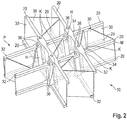
- Figure 2 shows the plan view of a fiber composite material component 10 according to the invention, which is obtained by a method according to the invention for producing the fiber composite material component 10 and has the structural and functional features described above.
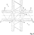
- Figure 3 shows a plan view of the fiber composite component 10 according to FIG Figure 2 .
- Figure 4 shows a sectional view through the in Figure 2 and Figure 3 fiber composite component 10 shown.
- the skewed fiber bundles 20 are arranged perpendicular to one another.
- Each one of these fiber bundles 20 forms, together with the matrix M in the profile P, a strut 32 which is part of the profile P.
- At least one cavity H is formed.
- the struts 32 each have a widening 34 in the area of their intersection K.
- At least one opening 36 is provided in the area of the widening 34.
- the opening 36 is, as in FIG Figure 4 shown connected to the cavity H.
- An opening 36 is provided at both longitudinal ends of the cavity H.
- Profile P shown can be part of a larger profile or already be a separate component.
- the profile P has two frame-like grids 38, each of which is formed from four crooked struts 32.
- the grids 38 are constructed essentially identically. They are located on two opposite sides of profile P and span profile P or serve as a skeleton for profile P.
- Two parallel struts 32 are provided in each grid 38 in a first plane and two further struts 32 parallel to one another are provided in a plane spaced apart from the plane.
- the parallel struts 32 of the first plane intersect and are arranged skewed and perpendicular to the parallel struts 32 of the second plane.
- a cavity H is formed in the area of each intersection K.
- the two grids 38 are connected to one another by means of several struts 30.
- the fiber composite component 10 shown can be described as follows:
- the fiber bundles 20 are here, as in Figure 1 , 2 and 3 shown, arranged at least on the outer edges of the profile P of the fiber composite component 10 and between the fiber bundles 20, bracing means 30, for example ribs and thrust surfaces, are provided and arranged so that a lattice-like profile structure can result.
- the fiber bundles 20 and the bracing means 30 are overmolded with thermoplastic or thermosetting material or the bracing means are produced by the injection molding onto the fiber bundles 20.
- the fibers 25 can be arranged in such a way that they absorb bending stresses and / or tensile stresses and / or compressive stresses.
- the bracing means 30 are arranged in such a way that they can transmit and / or absorb torsional forces and / or shear forces.
- the fiber bundles 20 are used dry. But it is also conceivable that they can be used pre-saturated.
- the strut means 30 can be formed from struts or thrust surfaces and it is also conceivable that the strut means are formed by injection molding of thermoplastic or thermosetting material or by fiber bundles 20.
- the fiber bundles 20 are arranged offset in the demolding direction so that they can be removed from the injection molding tool without a slide.
- the fiber bundles 20 are designed in such a way that they consist of straight areas and short curved areas and can thus approximately follow any curve.
- the cavity H is formed by internal pressure injection molding.
- Internal pressure injection molding can be internal gas pressure injection molding or internal pressure injection molding using fluid injection technology, in particular internal water pressure injection molding.
- the method according to the invention and the fiber composite material component 10 according to the invention make it possible to achieve spatial arrangements of the UD fiber bundles 20 with continuous fibers 25 which allow almost any shape.
- Stiff and stable profiles P can be achieved, which, moreover, can be significantly lighter than comparable, known profiles.
- a very high potential for lightweight construction is thus possible.
- any profile geometries or any component shapes can be generated and a lower material requirement is achieved. In particular, there is less waste or no waste.
- the cavities H are used to avoid accumulations of material.
- Internal pressure injection molding eliminates the need for slides or cores and simplifies production.
- the skeletal structure of the profile P advantageously enables a high torsional stiffness of the fiber composite material component 10.
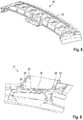
- Figure 5 shows a plan view of the tool W for the production according to the invention of a fiber composite material component 10 according to the invention, here a roof transverse element for a motor vehicle, namely a cowl.
- Figure 6 shows a representation of the section AA from Figure 5 and
- Figure 7 shows a representation of the section BB from Figure 5 .
- fiber composite component 10 has all of the foregoing in connection with Figure 1 features shown and described.
- fiber bundles 20 are spatially arranged as a profile P and bracing means 30 are arranged between the fiber bundles 20 and connect the fiber bundles 20 to one another.
- the fiber bundles 20 can as in connection with Figure 1 be described UD fiber bundle.
- exposed sections 22 are provided at regular intervals, on which no bracing means 30 are arranged.
- the fiber bundles 20 are placed directly in the tool W, as shown in particular in FIG Figure 6 and 7th is shown. Consequently, when thermoplastic or thermosetting material is injected, the fiber bundles 20 are fixed at this point in the tool and do not move out of the mold. A high degree of shape accuracy is therefore possible.
- the fiber bundles 20 can have exposed sections 22 at regular or irregular intervals.
- the exposed section 22 can be at least partially curved or straight.
- FIG. 11 shows a perspective illustration of the fiber composite material component 10 according to the invention according to FIG Figures 5 to 7 .
- Figures 9 and 10 is that broken in Figure 8 Fiber composite component 10 shown is shown.
- the fiber bundles 20 are each arranged in the edge regions of the fiber composite component 10. This ensures that the fibers of the fiber bundle 20 can absorb bending stresses and tensile stresses and compressive stresses.
- the strut means 30 are arranged in such a way that they transmit and / or absorb or absorb torsional forces and / or shear forces.
Claims (11)
- Composant en matériau composite de fibres (10) comprenant des faisceaux de fibres (20) et comprenant une matrice (M) en matière thermoplastique et/ou thermodurcissable, les faisceaux de fibres (20) étant agencés de telle sorte qu'ils forment un profilé (P), chaque faisceau de fibre (20) formant conjointement avec la matrice (M) dans le profilé (P) une entretoise (32), qui fait partie du profilé (P), des moyens d'entretoisement (30) étant agencés entre les faisceaux de fibres (20), au moins deux faisceaux de fibres (20) étant agencés en biais l'un par rapport à l'autre, et au moins les deux faisceaux de fibres (20) en biais et se croisant étant incorporés dans la matrice (M) dans la zone de leur croisement (K) de telle sorte que les entretoises (32) formées par les deux faisceaux de fibres en biais (20) présentent chacune un élargissement (34) dans cette zone, caractérisé en ce qu'au moins une ouverture (36) est prévue dans la zone de l'élargissement (34) et l'ouverture (36) est reliée à une cavité (H), qui est formée dans l'élargissement (34) .
- Composant en matériau composite de fibres (10) selon la revendication 1, caractérisé en ce que le composant en matériau composite de fibres (10) comprend au moins deux profilés (P) ou plus, au moins deux faisceaux de fibres (20) étant agencés en biais l'un par rapport à l'autre et se croisant par profilé (P), et au moins une cavité (H) étant formée dans la zone du croisement des faisceaux de fibres en biais (20).
- Composant en matériau composite de fibres (10) selon l'une quelconque des revendications précédentes, caractérisé en ce qu'au moins un faisceau de fibres (20) est un faisceau de fibres UD comprenant plusieurs fibres agencées unidirectionnellement.
- Composant en matériau composite de fibres (10) selon l'une quelconque des revendications précédentes, caractérisé en ce qu'au moins un faisceau de fibres (20) est constitué exclusivement de fibres agencées unidirectionnellement dans la direction de l'étendue du faisceau de fibres (20).
- Composant en matériau composite de fibres (10) selon l'une quelconque des revendications précédentes, caractérisé en ce qu'au moins un faisceau de fibres (20) comprend des premières fibres agencées unidirectionnellement dans la direction de l'étendue du faisceau de fibres (20) et des deuxièmes fibres agencées unidirectionnellement, avec lesquelles les premières fibres sont tressées.
- Composant en matériau composite de fibres (10) selon l'une quelconque des revendications précédentes, caractérisé en ce que les moyens d'entretoisement (30) sont ou comportent des nervures et/ou des surfaces de poussée et/ou en ce qu'au moins un faisceau de fibres (20) est agencé sur un bord du profilé du composant en matériau composite de fibres (10) et/ou en ce que les faisceaux de fibres (20) et les moyens d'entretoisement (30) forment un profilé spatial et/ou en ce que les faisceaux de fibres (20) sont agencés de telle sorte qu'ils absorbent ou peuvent absorber des contraintes de flexion et/ou des contraintes de traction et/ou des contraintes de compression, et/ou en ce que les moyens d'entretoisement (30) sont agencés de telle sorte qu'ils transmettent et/ou absorbent ou peuvent absorber des forces de torsion et/ou des forces de poussée.
- Composant en matériau composite de fibres (10) selon l'une quelconque des revendications précédentes, caractérisé en ce qu'au moins un faisceau de fibres (20) comprend au moins une section libre, sur laquelle aucun moyen d'entretoisement (30) n'est agencé, il étant de préférence prévu que les faisceaux de fibres (20) présentent des sections libres à des intervalles réguliers ou irréguliers, et/ou en ce que la section libre est au moins partiellement incurvée ou droite.
- Composant en matériau composite de fibres (10) selon l'une quelconque des revendications précédentes, caractérisé en ce que les moyens d'entretoisement (30) sont formés par des surfaces de poussée, et/ou en ce que les moyens d'entretoisement (30) sont formés par moulage par injection de matière thermoplastique et/ou thermodurcissable ou par des faisceaux de fibres (20), et/ou en ce que les faisceaux de fibres (20) sont agencés dans la direction de démoulage avec un décalage tel qu'ils peuvent être extraits sans coulisseau de l'outil de moulage par injection, et/ou en ce que le faisceau de fibres (20) est prévu avec des zones droites et/ou des zones incurvées.
- Procédé de fabrication d'un composant en matériau composite de fibres (10) selon la revendication 1 comprenant des faisceaux de fibres (20) et comprenant une matrice (M) en matière thermoplastique et/ou thermodurcissable, les faisceaux de fibres (20) étant agencés de telle sorte qu'ils forment un profilé (P), des moyens d'entretoisement (30) étant agencés entre les faisceaux de fibres (20), au moins deux faisceaux de fibres (20) étant agencés en biais l'un par rapport à l'autre, au moins une cavité (H) étant formée par moulage par injection à pression intérieure dans la zone du croisement (K) des faisceaux de fibres en biais (20) .
- Procédé selon la revendication 9, caractérisé en ce que le moulage par injection à pression intérieure est un moulage par injection à pression intérieure de gaz.
- Procédé selon la revendication 9, caractérisé en ce que le moulage par injection à pression intérieure est un moulage par injection à pression intérieure au moyen d'une technique d'injection de fluide, notamment un moulage par injection à pression intérieure d'eau.
Applications Claiming Priority (2)
| Application Number | Priority Date | Filing Date | Title |
|---|---|---|---|
| DE102014222933.2A DE102014222933B4 (de) | 2014-11-11 | 2014-11-11 | Faserverbundwerkstoffbauteil sowie Verfahren zur Herstellung eines Faserverbundwerkstoffbauteils |
| PCT/EP2015/073329 WO2016074863A1 (fr) | 2014-11-11 | 2015-10-09 | Élément structural en matériau renforcé par des fibres et son procédé de fabrication |
Publications (2)
| Publication Number | Publication Date |
|---|---|
| EP3218170A1 EP3218170A1 (fr) | 2017-09-20 |
| EP3218170B1 true EP3218170B1 (fr) | 2021-08-25 |
Family
ID=54260768
Family Applications (1)
| Application Number | Title | Priority Date | Filing Date |
|---|---|---|---|
| EP15775722.0A Active EP3218170B1 (fr) | 2014-11-11 | 2015-10-09 | Élément structural en matériau renforcé par des fibres et son procédé de fabrication |
Country Status (5)
| Country | Link |
|---|---|
| US (1) | US10220578B2 (fr) |
| EP (1) | EP3218170B1 (fr) |
| CN (1) | CN106794609B (fr) |
| DE (1) | DE102014222933B4 (fr) |
| WO (1) | WO2016074863A1 (fr) |
Families Citing this family (10)
| Publication number | Priority date | Publication date | Assignee | Title |
|---|---|---|---|---|
| DE102017200368A1 (de) * | 2017-01-11 | 2018-07-12 | Bayerische Motoren Werke Aktiengesellschaft | Spriegel eines Kraftfahrzeugs |
| US10584491B2 (en) * | 2017-03-06 | 2020-03-10 | Isotruss Industries Llc | Truss structure |
| US10180000B2 (en) * | 2017-03-06 | 2019-01-15 | Isotruss Industries Llc | Composite lattice beam |
| EP3470214B1 (fr) * | 2017-10-10 | 2021-06-16 | Groz-Beckert KG | Dispositif et procédé de fabrication d'un support comportant une pluralité de faisceaux de fibres |
| USD896401S1 (en) | 2018-03-06 | 2020-09-15 | Isotruss Industries Llc | Beam |
| USD895157S1 (en) | 2018-03-06 | 2020-09-01 | IsoTruss Indsutries LLC | Longitudinal beam |
| DE102018127011A1 (de) * | 2018-10-30 | 2020-04-30 | Bayerische Motoren Werke Aktiengesellschaft | Fahrzeugstrukturbauteil, Baukastensystem und Verfahren zur Herstellung von Fahrzeugstrukturbauteilen |
| USD967988S1 (en) * | 2020-06-03 | 2022-10-25 | Isotruss Industries Llc | Isogrid structure |
| CN114922095B (zh) * | 2022-03-18 | 2024-02-13 | 中国人民解放军陆军工程大学 | 一种装配式轻质高强纤维复合材料施工支架 |
| CN116001189B (zh) * | 2023-03-24 | 2023-10-20 | 达州增美玄武岩纤维科技有限公司 | 一种玄武岩纤维复合材料的注塑成型工艺 |
Family Cites Families (18)
| Publication number | Priority date | Publication date | Assignee | Title |
|---|---|---|---|---|
| CA1177459A (fr) | 1980-04-21 | 1984-11-06 | Lear Fan Corp. | Structure composite pour joindre les traverses entrecroisees d'un planeur ou d'une structure similaire |
| DE4003207A1 (de) | 1990-02-03 | 1991-08-08 | Heuer Michael Andree | Fachwerk aus fertigteilen |
| JP2745853B2 (ja) * | 1991-02-13 | 1998-04-28 | トヨタ自動車株式会社 | 中空frp成形体の製造方法 |
| CN1093031C (zh) * | 1996-10-08 | 2002-10-23 | 地方小型汽车公司 | 塑料模制件和结构构件以及其制造方法 |
| EP1581380B1 (fr) * | 2002-09-15 | 2007-03-07 | Weber Technology AG | Element structurel en matiere thermoplastique renforcee par des fibres |
| JP4993886B2 (ja) | 2005-09-07 | 2012-08-08 | 株式会社ディスコ | レーザー加工装置 |
| DE102006040748A1 (de) | 2006-08-31 | 2008-03-06 | Daimler Ag | Spritzgussverfahren für faserverstärkte Kraftfahrzeugteile |
| FR2931785B1 (fr) * | 2008-06-03 | 2010-12-31 | Peugeot Citroen Automobiles Sa | Capot de vehicule,dispositif et procede de fabrication par moulage d'un tel capot |
| WO2012105716A1 (fr) * | 2011-02-03 | 2012-08-09 | 帝人株式会社 | Élément de structure de véhicule |
| DE102011075688A1 (de) | 2011-05-11 | 2012-11-15 | SchäferRolls GmbH & Co. KG | Wellenanordnung und Verfahren zur Herstellung einer Wellenanordnung |
| KR20140030195A (ko) * | 2011-05-25 | 2014-03-11 | 데이진 가부시키가이샤 | 접합체 |
| RU2553299C1 (ru) * | 2011-05-31 | 2015-06-10 | Тейдзин Лимитед | Способ изготовления профилированного изделия с сохраняющейся изотропией |
| EP2752442A4 (fr) * | 2011-08-31 | 2015-01-28 | Teijin Ltd | Corps moulé comportant une surface surélevée et son procédé de production |
| US20140339036A1 (en) * | 2011-11-28 | 2014-11-20 | Teijin Limited | Shock Absorption Member |
| CN104011276A (zh) * | 2011-12-22 | 2014-08-27 | 帝人株式会社 | 无序毡和纤维增强复合材料 |
| US9415566B2 (en) * | 2012-08-21 | 2016-08-16 | Kabushiki Kaisha Toyota Jidoshokki | Three-dimensional fiber-reinforced composite material |
| US9539789B2 (en) * | 2012-08-21 | 2017-01-10 | Kabushiki Kaisha Toyota Jidoshokki | Three-dimensional fiber-reinforced composite and method for producing three-dimensional fiber-reinforced composite |
| DE102013219820A1 (de) | 2013-09-30 | 2015-04-02 | Bayerische Motoren Werke Aktiengesellschaft | Faserverbundwerkstoffbauteil, Verfahren zur Herstellung eines Faserverbundwerkstoffbauteils sowie Verwendung von Faserbündeln und Verstrebungsmitteln zur Herstellung eines Faserverbundwerkstoffbauteils |
-
2014
- 2014-11-11 DE DE102014222933.2A patent/DE102014222933B4/de active Active
-
2015
- 2015-10-09 CN CN201580045950.9A patent/CN106794609B/zh active Active
- 2015-10-09 WO PCT/EP2015/073329 patent/WO2016074863A1/fr active Application Filing
- 2015-10-09 EP EP15775722.0A patent/EP3218170B1/fr active Active
-
2017
- 2017-03-09 US US15/454,092 patent/US10220578B2/en active Active
Also Published As
| Publication number | Publication date |
|---|---|
| US10220578B2 (en) | 2019-03-05 |
| DE102014222933B4 (de) | 2021-09-09 |
| CN106794609A (zh) | 2017-05-31 |
| EP3218170A1 (fr) | 2017-09-20 |
| DE102014222933A1 (de) | 2016-05-12 |
| US20170173894A1 (en) | 2017-06-22 |
| WO2016074863A1 (fr) | 2016-05-19 |
| CN106794609B (zh) | 2019-03-01 |
Similar Documents
| Publication | Publication Date | Title |
|---|---|---|
| EP3218170B1 (fr) | Élément structural en matériau renforcé par des fibres et son procédé de fabrication | |
| EP3052306B1 (fr) | Élément en matériau composite renforcé par fibres et procédé de fabrication d'un élément en matériau composite renforcé par fibres | |
| DE102010003497B4 (de) | Verfahren zur Herstellung eines Aufprallschutzelementes | |
| EP2511084B1 (fr) | Elément de noeud en matière plastique renforcée de fibres et procédé de fabrication et d'utilisation associé | |
| EP0561151B1 (fr) | Procédé pour la fabrication de supports en matières synthétiques renforcées de fibres pour pare-choc de véhicules ainsi que supports similaires | |
| DE102010056293B4 (de) | Verfahren zum Herstellen eines hohlen Faserverbundbauteils und Formkörper | |
| EP2465665A1 (fr) | Procédé de fabrication d'un composant en matériau hybride | |
| DE102012109231B4 (de) | Integrale Verstärkungselemente | |
| DE4120133C2 (de) | Bauteil und Verfahren zur Herstellung eines solchen | |
| EP3165430B1 (fr) | Procédé de fabrication d'une structure de liaison comprenant au moins deux composants profilés, et structure de liaison et carrosserie | |
| DE102008011658A1 (de) | Verfahren zum Herstellen eines Faserverbund-Bauteils und Faserverbund-Bauteil | |
| EP2770096B1 (fr) | Barre en matériau synthétique pour des éléments de tricotage | |
| DE102008029518B4 (de) | Verfahren zur Herstellung von Faserverbundbauteilen und Faserverbundbauteile | |
| DE102008023208A1 (de) | Bauteil in Hybridbauweise | |
| WO2014095856A2 (fr) | Dispositif de moulage variable pour fabriquer une demi-coque pour une pale de rotor d'éolienne | |
| DE102006050823A1 (de) | Verbundbauteil sowie Verfahren zu dessen Herstellung | |
| DE102014017809B4 (de) | Verfahren zur Herstellung eines Strukturbauteils | |
| DE102021105792A1 (de) | Sandwichbauteil, Turbinen-Strahltriebwerk und Verfahren zu dessen Herstellung | |
| EP3599084B1 (fr) | Procédé de fabrication d'un composite en matière plastique fibreuse | |
| EP3710339B1 (fr) | Dispositif de renforcement, d'étanchéité ou d'amortissement d'un élément structurel | |
| DE102016117103A1 (de) | Verfahren zur Herstellung eines Faserverbundbauteils | |
| DE102011003747A1 (de) | Faserverstärktes Bauteil und Verfahren zur Herstellung eines faserverstärkten Bauteils | |
| DE102018125243A1 (de) | Kernbauteil für ein Aerodynamikbauteil eines Fahrzeugs | |
| EP2719521A1 (fr) | Gousset en élastomère | |
| EP0603812B1 (fr) | Panneau nervuré en matière plastique renforcé de fibres et procédé pour sa fabrication |
Legal Events
| Date | Code | Title | Description |
|---|---|---|---|
| STAA | Information on the status of an ep patent application or granted ep patent |
Free format text: STATUS: THE INTERNATIONAL PUBLICATION HAS BEEN MADE |
|
| PUAI | Public reference made under article 153(3) epc to a published international application that has entered the european phase |
Free format text: ORIGINAL CODE: 0009012 |
|
| STAA | Information on the status of an ep patent application or granted ep patent |
Free format text: STATUS: REQUEST FOR EXAMINATION WAS MADE |
|
| 17P | Request for examination filed |
Effective date: 20170403 |
|
| AK | Designated contracting states |
Kind code of ref document: A1 Designated state(s): AL AT BE BG CH CY CZ DE DK EE ES FI FR GB GR HR HU IE IS IT LI LT LU LV MC MK MT NL NO PL PT RO RS SE SI SK SM TR |
|
| AX | Request for extension of the european patent |
Extension state: BA ME |
|
| DAV | Request for validation of the european patent (deleted) | ||
| DAX | Request for extension of the european patent (deleted) | ||
| GRAP | Despatch of communication of intention to grant a patent |
Free format text: ORIGINAL CODE: EPIDOSNIGR1 |
|
| STAA | Information on the status of an ep patent application or granted ep patent |
Free format text: STATUS: GRANT OF PATENT IS INTENDED |
|
| INTG | Intention to grant announced |
Effective date: 20210519 |
|
| GRAS | Grant fee paid |
Free format text: ORIGINAL CODE: EPIDOSNIGR3 |
|
| GRAA | (expected) grant |
Free format text: ORIGINAL CODE: 0009210 |
|
| STAA | Information on the status of an ep patent application or granted ep patent |
Free format text: STATUS: THE PATENT HAS BEEN GRANTED |
|
| AK | Designated contracting states |
Kind code of ref document: B1 Designated state(s): AL AT BE BG CH CY CZ DE DK EE ES FI FR GB GR HR HU IE IS IT LI LT LU LV MC MK MT NL NO PL PT RO RS SE SI SK SM TR |
|
| REG | Reference to a national code |
Ref country code: CH Ref legal event code: EP |
|
| REG | Reference to a national code |
Ref country code: DE Ref legal event code: R096 Ref document number: 502015015113 Country of ref document: DE |
|
| REG | Reference to a national code |
Ref country code: IE Ref legal event code: FG4D Free format text: LANGUAGE OF EP DOCUMENT: GERMAN Ref country code: AT Ref legal event code: REF Ref document number: 1423354 Country of ref document: AT Kind code of ref document: T Effective date: 20210915 |
|
| REG | Reference to a national code |
Ref country code: LT Ref legal event code: MG9D |
|
| REG | Reference to a national code |
Ref country code: NL Ref legal event code: MP Effective date: 20210825 |
|
| PG25 | Lapsed in a contracting state [announced via postgrant information from national office to epo] |
Ref country code: RS Free format text: LAPSE BECAUSE OF FAILURE TO SUBMIT A TRANSLATION OF THE DESCRIPTION OR TO PAY THE FEE WITHIN THE PRESCRIBED TIME-LIMIT Effective date: 20210825 Ref country code: SE Free format text: LAPSE BECAUSE OF FAILURE TO SUBMIT A TRANSLATION OF THE DESCRIPTION OR TO PAY THE FEE WITHIN THE PRESCRIBED TIME-LIMIT Effective date: 20210825 Ref country code: HR Free format text: LAPSE BECAUSE OF FAILURE TO SUBMIT A TRANSLATION OF THE DESCRIPTION OR TO PAY THE FEE WITHIN THE PRESCRIBED TIME-LIMIT Effective date: 20210825 Ref country code: BG Free format text: LAPSE BECAUSE OF FAILURE TO SUBMIT A TRANSLATION OF THE DESCRIPTION OR TO PAY THE FEE WITHIN THE PRESCRIBED TIME-LIMIT Effective date: 20211125 Ref country code: LT Free format text: LAPSE BECAUSE OF FAILURE TO SUBMIT A TRANSLATION OF THE DESCRIPTION OR TO PAY THE FEE WITHIN THE PRESCRIBED TIME-LIMIT Effective date: 20210825 Ref country code: PT Free format text: LAPSE BECAUSE OF FAILURE TO SUBMIT A TRANSLATION OF THE DESCRIPTION OR TO PAY THE FEE WITHIN THE PRESCRIBED TIME-LIMIT Effective date: 20211227 Ref country code: NO Free format text: LAPSE BECAUSE OF FAILURE TO SUBMIT A TRANSLATION OF THE DESCRIPTION OR TO PAY THE FEE WITHIN THE PRESCRIBED TIME-LIMIT Effective date: 20211125 Ref country code: ES Free format text: LAPSE BECAUSE OF FAILURE TO SUBMIT A TRANSLATION OF THE DESCRIPTION OR TO PAY THE FEE WITHIN THE PRESCRIBED TIME-LIMIT Effective date: 20210825 Ref country code: FI Free format text: LAPSE BECAUSE OF FAILURE TO SUBMIT A TRANSLATION OF THE DESCRIPTION OR TO PAY THE FEE WITHIN THE PRESCRIBED TIME-LIMIT Effective date: 20210825 |
|
| PG25 | Lapsed in a contracting state [announced via postgrant information from national office to epo] |
Ref country code: PL Free format text: LAPSE BECAUSE OF FAILURE TO SUBMIT A TRANSLATION OF THE DESCRIPTION OR TO PAY THE FEE WITHIN THE PRESCRIBED TIME-LIMIT Effective date: 20210825 Ref country code: LV Free format text: LAPSE BECAUSE OF FAILURE TO SUBMIT A TRANSLATION OF THE DESCRIPTION OR TO PAY THE FEE WITHIN THE PRESCRIBED TIME-LIMIT Effective date: 20210825 Ref country code: GR Free format text: LAPSE BECAUSE OF FAILURE TO SUBMIT A TRANSLATION OF THE DESCRIPTION OR TO PAY THE FEE WITHIN THE PRESCRIBED TIME-LIMIT Effective date: 20211126 |
|
| PG25 | Lapsed in a contracting state [announced via postgrant information from national office to epo] |
Ref country code: NL Free format text: LAPSE BECAUSE OF FAILURE TO SUBMIT A TRANSLATION OF THE DESCRIPTION OR TO PAY THE FEE WITHIN THE PRESCRIBED TIME-LIMIT Effective date: 20210825 |
|
| PG25 | Lapsed in a contracting state [announced via postgrant information from national office to epo] |
Ref country code: DK Free format text: LAPSE BECAUSE OF FAILURE TO SUBMIT A TRANSLATION OF THE DESCRIPTION OR TO PAY THE FEE WITHIN THE PRESCRIBED TIME-LIMIT Effective date: 20210825 |
|
| REG | Reference to a national code |
Ref country code: DE Ref legal event code: R097 Ref document number: 502015015113 Country of ref document: DE |
|
| REG | Reference to a national code |
Ref country code: CH Ref legal event code: PL |
|
| PG25 | Lapsed in a contracting state [announced via postgrant information from national office to epo] |
Ref country code: SM Free format text: LAPSE BECAUSE OF FAILURE TO SUBMIT A TRANSLATION OF THE DESCRIPTION OR TO PAY THE FEE WITHIN THE PRESCRIBED TIME-LIMIT Effective date: 20210825 Ref country code: SK Free format text: LAPSE BECAUSE OF FAILURE TO SUBMIT A TRANSLATION OF THE DESCRIPTION OR TO PAY THE FEE WITHIN THE PRESCRIBED TIME-LIMIT Effective date: 20210825 Ref country code: RO Free format text: LAPSE BECAUSE OF FAILURE TO SUBMIT A TRANSLATION OF THE DESCRIPTION OR TO PAY THE FEE WITHIN THE PRESCRIBED TIME-LIMIT Effective date: 20210825 Ref country code: EE Free format text: LAPSE BECAUSE OF FAILURE TO SUBMIT A TRANSLATION OF THE DESCRIPTION OR TO PAY THE FEE WITHIN THE PRESCRIBED TIME-LIMIT Effective date: 20210825 Ref country code: CZ Free format text: LAPSE BECAUSE OF FAILURE TO SUBMIT A TRANSLATION OF THE DESCRIPTION OR TO PAY THE FEE WITHIN THE PRESCRIBED TIME-LIMIT Effective date: 20210825 Ref country code: AL Free format text: LAPSE BECAUSE OF FAILURE TO SUBMIT A TRANSLATION OF THE DESCRIPTION OR TO PAY THE FEE WITHIN THE PRESCRIBED TIME-LIMIT Effective date: 20210825 |
|
| REG | Reference to a national code |
Ref country code: BE Ref legal event code: MM Effective date: 20211031 |
|
| PG25 | Lapsed in a contracting state [announced via postgrant information from national office to epo] |
Ref country code: MC Free format text: LAPSE BECAUSE OF FAILURE TO SUBMIT A TRANSLATION OF THE DESCRIPTION OR TO PAY THE FEE WITHIN THE PRESCRIBED TIME-LIMIT Effective date: 20210825 |
|
| PLBE | No opposition filed within time limit |
Free format text: ORIGINAL CODE: 0009261 |
|
| STAA | Information on the status of an ep patent application or granted ep patent |
Free format text: STATUS: NO OPPOSITION FILED WITHIN TIME LIMIT |
|
| GBPC | Gb: european patent ceased through non-payment of renewal fee |
Effective date: 20211125 |
|
| PG25 | Lapsed in a contracting state [announced via postgrant information from national office to epo] |
Ref country code: LU Free format text: LAPSE BECAUSE OF NON-PAYMENT OF DUE FEES Effective date: 20211009 Ref country code: IT Free format text: LAPSE BECAUSE OF FAILURE TO SUBMIT A TRANSLATION OF THE DESCRIPTION OR TO PAY THE FEE WITHIN THE PRESCRIBED TIME-LIMIT Effective date: 20210825 Ref country code: BE Free format text: LAPSE BECAUSE OF NON-PAYMENT OF DUE FEES Effective date: 20211031 |
|
| 26N | No opposition filed |
Effective date: 20220527 |
|
| PG25 | Lapsed in a contracting state [announced via postgrant information from national office to epo] |
Ref country code: SI Free format text: LAPSE BECAUSE OF FAILURE TO SUBMIT A TRANSLATION OF THE DESCRIPTION OR TO PAY THE FEE WITHIN THE PRESCRIBED TIME-LIMIT Effective date: 20210825 Ref country code: LI Free format text: LAPSE BECAUSE OF NON-PAYMENT OF DUE FEES Effective date: 20211031 Ref country code: CH Free format text: LAPSE BECAUSE OF NON-PAYMENT OF DUE FEES Effective date: 20211031 |
|
| PG25 | Lapsed in a contracting state [announced via postgrant information from national office to epo] |
Ref country code: FR Free format text: LAPSE BECAUSE OF NON-PAYMENT OF DUE FEES Effective date: 20211025 |
|
| PG25 | Lapsed in a contracting state [announced via postgrant information from national office to epo] |
Ref country code: IE Free format text: LAPSE BECAUSE OF NON-PAYMENT OF DUE FEES Effective date: 20211009 Ref country code: GB Free format text: LAPSE BECAUSE OF NON-PAYMENT OF DUE FEES Effective date: 20211125 |
|
| REG | Reference to a national code |
Ref country code: AT Ref legal event code: MM01 Ref document number: 1423354 Country of ref document: AT Kind code of ref document: T Effective date: 20211009 |
|
| PG25 | Lapsed in a contracting state [announced via postgrant information from national office to epo] |
Ref country code: AT Free format text: LAPSE BECAUSE OF NON-PAYMENT OF DUE FEES Effective date: 20211009 |
|
| PG25 | Lapsed in a contracting state [announced via postgrant information from national office to epo] |
Ref country code: HU Free format text: LAPSE BECAUSE OF FAILURE TO SUBMIT A TRANSLATION OF THE DESCRIPTION OR TO PAY THE FEE WITHIN THE PRESCRIBED TIME-LIMIT; INVALID AB INITIO Effective date: 20151009 |
|
| P01 | Opt-out of the competence of the unified patent court (upc) registered |
Effective date: 20230503 |
|
| PG25 | Lapsed in a contracting state [announced via postgrant information from national office to epo] |
Ref country code: CY Free format text: LAPSE BECAUSE OF FAILURE TO SUBMIT A TRANSLATION OF THE DESCRIPTION OR TO PAY THE FEE WITHIN THE PRESCRIBED TIME-LIMIT Effective date: 20210825 |
|
| PGFP | Annual fee paid to national office [announced via postgrant information from national office to epo] |
Ref country code: DE Payment date: 20231017 Year of fee payment: 9 |
|
| PG25 | Lapsed in a contracting state [announced via postgrant information from national office to epo] |
Ref country code: MK Free format text: LAPSE BECAUSE OF FAILURE TO SUBMIT A TRANSLATION OF THE DESCRIPTION OR TO PAY THE FEE WITHIN THE PRESCRIBED TIME-LIMIT Effective date: 20210825 |