EP2371527B1 - Procédé et dispositif de fabrication de sachets (de tabac) - Google Patents
Procédé et dispositif de fabrication de sachets (de tabac) Download PDFInfo
- Publication number
- EP2371527B1 EP2371527B1 EP11002623.4A EP11002623A EP2371527B1 EP 2371527 B1 EP2371527 B1 EP 2371527B1 EP 11002623 A EP11002623 A EP 11002623A EP 2371527 B1 EP2371527 B1 EP 2371527B1
- Authority
- EP
- European Patent Office
- Prior art keywords
- bag
- hook
- loop
- strips
- strip
- Prior art date
- Legal status (The legal status is an assumption and is not a legal conclusion. Google has not performed a legal analysis and makes no representation as to the accuracy of the status listed.)
- Not-in-force
Links
Images


Classifications
-
- B—PERFORMING OPERATIONS; TRANSPORTING
- B65—CONVEYING; PACKING; STORING; HANDLING THIN OR FILAMENTARY MATERIAL
- B65D—CONTAINERS FOR STORAGE OR TRANSPORT OF ARTICLES OR MATERIALS, e.g. BAGS, BARRELS, BOTTLES, BOXES, CANS, CARTONS, CRATES, DRUMS, JARS, TANKS, HOPPERS, FORWARDING CONTAINERS; ACCESSORIES, CLOSURES, OR FITTINGS THEREFOR; PACKAGING ELEMENTS; PACKAGES
- B65D33/00—Details of, or accessories for, sacks or bags
- B65D33/16—End- or aperture-closing arrangements or devices
- B65D33/24—End- or aperture-closing arrangements or devices using self-locking integral or attached closure elements, e.g. flaps
-
- B—PERFORMING OPERATIONS; TRANSPORTING
- B31—MAKING ARTICLES OF PAPER, CARDBOARD OR MATERIAL WORKED IN A MANNER ANALOGOUS TO PAPER; WORKING PAPER, CARDBOARD OR MATERIAL WORKED IN A MANNER ANALOGOUS TO PAPER
- B31B—MAKING CONTAINERS OF PAPER, CARDBOARD OR MATERIAL WORKED IN A MANNER ANALOGOUS TO PAPER
- B31B70/00—Making flexible containers, e.g. envelopes or bags
- B31B70/74—Auxiliary operations
- B31B70/81—Forming or attaching accessories, e.g. opening devices, closures or tear strings
- B31B70/812—Applying patches, strips or strings on sheets or webs
- B31B70/8123—Applying strips
-
- B—PERFORMING OPERATIONS; TRANSPORTING
- B65—CONVEYING; PACKING; STORING; HANDLING THIN OR FILAMENTARY MATERIAL
- B65D—CONTAINERS FOR STORAGE OR TRANSPORT OF ARTICLES OR MATERIALS, e.g. BAGS, BARRELS, BOTTLES, BOXES, CANS, CARTONS, CRATES, DRUMS, JARS, TANKS, HOPPERS, FORWARDING CONTAINERS; ACCESSORIES, CLOSURES, OR FITTINGS THEREFOR; PACKAGING ELEMENTS; PACKAGES
- B65D2313/00—Connecting or fastening means
- B65D2313/02—Connecting or fastening means of hook-and-loop type
Definitions
- the invention relates to a method for producing (tobacco) bag packages with Velcro pieces for fixing a tab in the closed position and the other features in the preamble of claim 1. Furthermore, the invention relates to a device for carrying out the method.
- Pouches made of film are known with a tab, in particular tobacco pouches with a closure tab or winding tab designed as continuation of a pouch rear wall, and with hook and loop fasteners for fixing the tab in the closed position on a pouch front wall or on a pouch back wall (US Pat. EP 1 215 973 B1 ).
- the strip-shaped Velcro pieces are positioned in this known embodiment of a (tobacco) bag in transverse relative position to each other on the tab on the one hand and the bag wall on the other.
- a first hook and loop fastener on the inside of the flap and a second hook and loop piece are attached separately to a bag wall position corresponding to the closed position of the flap.
- the Velcro pieces are permanently fixed by gluing on the tab or on the bag wall. The production of the so-formed bag packages is complicated and often imprecise in terms of the positioning of the Velcro pieces.
- the invention has for its object to avoid the above problems in the production of packages with Velcro pieces for fixing a tab and in particular to improve the attachment of the Velcro pieces in an exact relative position.
- the inventive method is characterized by the features of claim 1.
- the particular rectangular or square Velcro pieces are therefore first connected with their adhesive coating, in particular with their Velcro coating into a unit of two pieces.
- This unit is then either applied to the (closure) tab or to the packing or bag wall and bonded thereto by gluing or otherwise.
- This process step is performed with the package open or the bag open. Thereafter, the tab is brought into the closed position, wherein, depending on the position of the unit from the connecting pieces, the free side of one of the connecting pieces of the unit is connected either to the tab or to a packing or bag wall.
- the Velcro pieces are preferably separated from a strip of material, wherein according to the invention two continuous Velcro strips in the region of the Velcro coating are adjacent to each other and are connected by pressing against each other. From this double strip then appropriate units of (two) Klett pieces are separated and fed to a pack.
- the double strips of two Velcro strips can be made from single, continuous Velcro strips by merging and pressing together directly in the processing area.
- a strip of material with at least two juxtaposed and parallel Velcro strips.
- This starting web is folded along a line between adjacent Velcro strips, such that the two Velcro strips can face each other and be joined together by compression.
- the material web or a carrier tape for the (two) Velcro strips is preferably provided with a weakening line, so that the material strip can be severed during the assembly of the Velcro strips.
- a separation of the unit after attachment to the package or the bag, wherein the relative position is selected so that the carrier is severed during the opening process and associated separation of the Velcro pieces.
- the invention relates to devices for producing the Klätinnism and for transmitting the same on (tobacco) bag.
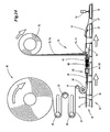
- the preferred field of application for the innovations are methods and apparatus for producing foil pouches, in particular in the form of tobacco pouches 10 for receiving a portion of tobacco.
- This consists of a pocket 11, which is formed by folding a corresponding (rectangular) foil blank, with bag front wall 12 and bag rear wall 13.
- the bag walls 12, 13 are connected to each other by side seams 14 due to thermal sealing.
- a removal opening 15 between the bag walls 12, 13 is closed by transverse sealing seam - after filling the bag 11.
- the closure seam 16 is designed such that it can be easily opened when the package is put into use.
- the tobacco bag 10 has a tab 17 which is formed as an extension of the bag rear wall 13 and thus as part of the one-piece foil blank.
- the tab 17 may be sized so that it is folded as a closure tab against the bag front wall 12 and connected thereto.
- the lug 17 is designed as a winding lug which, in the closed position, encloses the bag front wall 12 and is detachably fixed to the bag rear wall 13 by means of an edge-side connecting means ( Fig. 3 ).
- connecting pieces are provided, which are on the one hand on the (inside of) the tab 17 and on the other hand attached to the bag wall 12 or 13.
- the connecting pieces are designed so that they enter into a releasable connection due to pressing against each other.
- the connecting pieces are formed as Velcro pieces 18, 19.
- the Velcro pieces 18, 19, preferably in a matching embodiment, have on the mutually facing sides of a strip-shaped carrier 21 each have a hook and loop coating 20.
- a permanently acting adhesive 22 is arranged. By this adhesive 22, the Velcro pieces 18, 19 are attached to the tobacco bag 10 in the manner described.
- a special feature is that the Velcro pieces 18, 19 of the pack or the tobacco bag 10 are supplied as a prefabricated unit 23. Two Velcro pieces 18, 19 are joined together in the area of the Velcro coating 20 to form the unit 23. The free sides of the unit 23 and the Velcro pieces 18, 19 are preferably provided with the adhesive 22. This can alternatively be applied to the package or to the tobacco bag 10 in the region of the hook and loop pieces 18, 19 to be attached.
- Each tobacco pouch 10 is provided with at least one unit 23. This can be attached in a first step on the inside of the tab 17 packaged, namely by means of adhesive 22 of a hook and loop fastener 18 are attached. Thereafter, the tab 17 is brought into the closed position ( Fig. 3 ), whereby the free side of the unit 23 and the other Klett Cultures 19 receives investment on the bag front wall 12 or - preferably - on the bag rear wall 13. Again, the unit 23 is fixed by means of adhesive 22. Now, the tobacco bag 10 and the tab 17 can be opened and closed several times in the usual way, each with separation and rejoining the Velcro pieces 18, 19th
- the unit 23 may be attached to the bag wall, preferably the bag back wall 13, in a first step, preferably after filling and Closing the bag 11.
- the unit 23 is connected to the tab 17 also in this procedure.
- a respective hook and loop piece 18 is connected to the tab 17 and a hook and loop piece 19 to the bag rear wall 13.
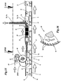
- the units 23 can be manufactured in the region of a packaging machine and fed to the tobacco bags 10 in a transfer station 24. Alternatively, otherwise manufactured units 23 may be conveniently transferred to the transfer station 24.
- the double strip 27 can be created in different ways.
- Fig. 4 such as 10 to FIG. 13 two separate Velcro strips 25, 26 are brought together, such that the Velcro coatings 20 are facing each other.
- Velcro strips 25, 26 are connected together to form a continuous double strip 27th
- the two Velcro tapes 25, 26 to be united are stored (above the transfer station 24) as adjacent strip robots 28, 29. Of these, the bands 25, 26 are withdrawn and fed to the transfer station 24 via first stationary deflection rollers 30 in horizontal loops. Above and below movable dancer rollers 31, 32 are arranged, which perform (in the horizontal plane) a compensating movement and a constant tension in the Velcro strips 25, 26 obtained. Lower stationary (second) guide rollers 33 guide the hook and loop fasteners 25, 26 in a converging downward direction to a connecting member. This has pressure rollers 34, 35 on both sides of the Velcro strips 25, 26. The rollers are driven according to the direction of movement of the Velcro strips 25, 26 (arrows). Of the Distance of the lateral surfaces is chosen so that the Velcro strips 25, 26 are brought together in the area of the Velcro coatings 20 and interconnected.
- the lateral surfaces of the pressure rollers 34, 35 are formed in a special way, according to the embodiment Fig. 13 with convergent projections, which are tooth-shaped in the present case. The tips of these projections receive contact with the adhesive side of the Velcro strips 25, 26. Additionally or alternatively, the lateral surface of the pressure rollers 34, 35 or the projections may be provided with a silicone coating to adhere the Velcro strips 25, 26 to the pressure rollers 34, 35 to avoid.
- a separating member for the production of the units 23.
- This consists of separating knives, in this case from a stationary cutting blade 36 with trapezoidal cross-section.
- a counter knife 37 arranged below the separating knife 36 is movable transversely to the plane of the double strip 27 and, in cooperation with the separating knife 36, separates a unit 23 from the double strip 27 at each working cycle. This is transmitted by the counter knife 37 to a holder 38.
- the counter knife 37 forms by trapezoidal cross-sectional shape an (upper) cutting edge 39.
- a compensating piece preferably made of silicone, on which the separated unit 23 rests in the separation process.
- suction holes 40 are arranged, which open at a (vertical) contact surface of the counter blade 37 and are connected to a suction channel 41 in the counter blade 37.
- the unit 23 abuts against the (coated with silicone) contact surface of the counter blade 37 and is held (in addition) by suction.
- the unit 23 In the end position of the transverse movement of the counter blade 37, the unit 23 receives contact with a holder 38, which takes over the unit 23.
- the holder 38 is provided with a pad 42 of silicone or other suitable material.
- the unit 23 is held on the pad 42, in particular by suction, which is generated via suction holes 43.
- suction When transferring the unit 23 from one carrier to the other, the suction air is blocked in the area of the counter blade 37, optionally reversed in compressed air. At the same time, the suction air on the suction holes 43 on the holder 38 is effective.
- the double strip 27 is assigned a support element arranged above the knives 36, 37.
- This consists of a rotationally driven support roller 68, which is arranged on the opposite side of the counter-blade 36 of the double strip 27.
- the support roller 85 is provided with measures that prevent sticking of the double strip 27, in particular with tooth-like projections and / or silicone coating.
- the holder 38 is used for further transport of the unit 23.
- the holder 38 serves for (direct) transmission of the unit 23 to a tobacco pouch 10.
- a plurality of, in the present case four holders 38 are arranged on a movable carrier, in particular on a cyclically rotating transfer roller 44, as a radially projecting, with the same Spaced apart stamps, at the outer end of the unit 23 is held.
- the relative position of the above a trajectory for the tobacco bag 10, in particular above a bag path 45 arranged transfer member 44 is selected so that during a standstill phase, a unit 23 in the region of the separation station 37, 38 taken over and at the same time - by a downwardly directed holder 38 - a Unit 23 is transferred to a tobacco bag 10.
- the tobacco pouches 10 are cyclically transported by a (horizontal) bag conveyor 45, the bag 11 filled with tobacco and closed in the region of the removal opening 15 lying on a belt 46 with drivers 47 on both sides (front and rear) of the tobacco pouch 10.
- Each tobacco pouch 10 is suitably positioned and aligned between the dogs 47.
- the (winding) tab 17 is already partially wrapped after closing the bag 11, so that the bag front wall 12 is directed with the voltage applied to this part of the tab 17 down and rests on the belt 46.
- the bag rear wall 13 facing part of the tab 17 is directed upwards as a free leg and receives investment - approximately in the vertical plane - on a stationary guide, here on a guide rail 48, against which the tab 17 and the free leg slidably.
- the units 23 are placed on the upwardly directed bag rear wall 13.
- the suction air in the region of the holder 38 is controlled away, optionally, compressed air is transmitted, so that the unit 23 reliably on the Tobacco bag 10 is transferred.
- the tab 17 is folded into the closed position or until it rests against the bag rear wall 13. At the same time the tab 17 is connected to the free, coated with adhesive 22 side of the unit 23.
- a ram 84 arranged above the pouch web 45 acts, which exerts pressure in the area of the velcro pieces 18, 19 on the outside of the pouch 10 or the flap 17 to stabilize the connection.
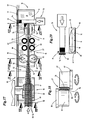
- the (Velcro) unit 23 is made of a special strip of material 49, which is supplied as an industrial precursor of the packaging machine.
- the material strip 49 consists of a strip-shaped carrier tape 50, in particular made of plastic.
- Each Velcro strip 51, 52 consists of erected Velcro structures, in particular of hook-shaped projections 53 (in detail in FIG Fig. 16 ). These can be applied to the carrier tape 50 or be formed by appropriate shaping of the material of the carrier tape.
- the mutually parallel Velcro strips 51, 52 are positioned at a distance from each other on the carrier tape 50. Between the adjacent Velcro strips 51, 52 a folding edge 54 is formed. This can be defined by a weakening line, in particular by a perforation line, preferably centrally between the Velcro strips 51, 52. Adjacent to the Velcro strips 51, 52, ie on the free side of the carrier tape 50, an adhesive is attached, here a continuous layer of adhesive 22. Furthermore, a cover of the free side of the adhesive 22 is provided in the present case, namely a cover strip of thin film , This is removed before separating the units 23. In the illustrated embodiment, a material strip 49 two cover strips 55, 56 assigned. These are shared or divisible. In the example of Fig.
- the cover strips 55, 56 associated with each Velcro strip 51, 52 are centered, namely in the region of the folded edge 54, separated from one another by a continuous gap 57 or are easily separable by a correspondingly attached perforation.
- the material strip 49 is deformed, namely folded in the longitudinal direction between the Velcro strips 51, 52, as a result, a double strip 27 is formed in which the adjacent Velcro strips 51, 52 due to the Velcro connection to each other ( Fig. 18 ).
- a double strip 27 is formed in which the adjacent Velcro strips 51, 52 due to the Velcro connection to each other ( Fig. 18 ).
- the cover strips 55, 56 are thereby separated, but initially still remain in the covering position. From the resulting double strip 27, the units 23 can be separated, in particular after prior removal of the cover strip 55, 56th
- a belt bobbin 58 is positioned as a supply for the material strip 49 in the region of the transfer station 24 above a movement path of the tobacco bag 10, in particular above the bag conveyor 45 in the embodiment described.
- the material strip 49 is preferably clocked withdrawn from the belt bobbin 58 and fed via movably mounted deflection rollers 59 a manufacturing section 62 for producing the units 23.
- the (unfolded) strip of material 49 is guided above the movement path of the tobacco bag 10 via a further deflection roller, which is also the drive or preferred roller 60 for the material strip 49. With the help of a guide roller, namely roughing roller 61, a wrap angle of at least 180 ° is created. Subsequent to the preferred roller 60, the material strip 49 is transported into the (horizontal) production section 62.
- the preferred roller 60 is designed in a special way ( Fig. 16 ), namely provided with particular sawtooth-like drivers 63 on the circumference. These are matched to the structure of the Velcro strips 51, 52 in terms of training, arrangement and dimension. Conveniently, the projections 53 and hook-shaped connecting members are arranged in ordered formation, in particular in transverse rows. The dogs 63 of the preferred roller 60 enter into areas between adjacent projections 53 and transverse rows of the same, in order to promote the material strip 49 or Velcro strips 25, 26 without slipping.
- the feed roller 60 is driven cyclically, namely according to the production of a unit 23 by separating from the web 49.
- the roughing roller 61 is synchronously with the (cyclic) conveying movement of the web 49 in the circumferential direction of the preferred roller 60 back and forth to compensate for movement without effect to effect on the balancing or deflection rollers 59.
- a folding station adjoining the preferred roller 60 in the conveying direction is formed.
- the V-shaped folding of the material strip 49 takes place in the region between the preferred roller 60 and members for compressing the legs of the folded strip of material 49 (FIGS. Fig. 18 ).
- rotatable pressure rollers 64, 65 about upright axes are arranged on both sides of the movement path of the material strip 49.
- the spread in a horizontal plane (running from the feed roller 60) strip of material 49 is folded on the way to the pressure rollers 64, 65, so that the legs formed, each with a Velcro strips 51, 52 in the region of the pressure rollers 64, 65 to each other ( Fig. 18 ).
- the pressure rollers 64, 65 have (mutually) edge-side guide discs 66, 67, which cause a guide of the (folded) material strip 46 in the vertical direction.
- the prepared, namely folded strip of material 49 is fed in a preferably vertical orientation of a separation station for separating the units 23 successively at the front end of the formed from the strip of material 49 double stripe 27.
- a separation station for separating the units 23 successively at the front end of the formed from the strip of material 49 double stripe 27.
- are in an area between the Pressure rollers 64, 65 and a separating member further preferred rollers 68, 69 arranged in pairs on both sides of the double strip 27.
- the preferred rollers 68, 69 are preferably provided with a peripheral coating made of plastic, rubber or other material with a high coefficient of friction and preferably geared so with the preferred roller 60 that a coordinated transport of the material strip 49 and the double strip 27 takes place.
- the cover strips 55, 56 are eliminated.
- the cover strips 55, 56 exposed on both sides of the double strip 27 are pulled off the respective layer of the adhesive 22 and led out of the region of the double strip 27 by deflection.
- the peeled cover strips 55, 56 are moved upwards and wound onto a collecting rack 72.
- a separator This consists in the present example of a combined separating and pressing member, in particular a cutting punch 73.
- a cutting punch 73 This is above the trajectory of the tobacco pouch 10 fixedly positioned and transversely movable, in height or in the plane of the transport path also above the bag 10 Double strip 27.
- the cutting punch 73 is transversely movable in a cutting station (arrow).
- a front end of the cutting punch 73 is provided with a separating knife 74 or designed as a separating knife (with trapezoidal cross-section). In a starting position, separating blades 74 and counter blades 75 are located on opposite sides of the double strip 27.
- a unit 23 is separated from the double strip 27 the cutting punch 73 detected and with continued movement of the cutting punch 73 until it rests against the bag 10, in this case at the upright positioned tab 17.
- the unit 23 is pressed by the cutting punch 73 against the inside of the tab 17.
- a counter-pressure member 76 plate is positioned on the opposite side of the tab 17 so that sufficient pressure for fixing the unit 23 can be transferred. The cutting punch 23 then returns to the starting position.
- transverse guide members or cylindrical guide rods 79 are arranged above and below the movement path of the double strip 27, in the conveying direction in front of the cutting punch 73 or in front of the deflecting rods 70, 71. As a result, the double strip 27 is aligned in height exactly.
- the tobacco bag 10 is folded after attaching the unit 23 with continued transport.
- the tab 17 is folded against the pocket 11 and against the bag rear wall 13 in the horizontal position.
- a Guide rail 77 effective, which runs above the path of movement of the tobacco bag 10 at the level of the tab 17 and due to arcuate design, the process of folding the flap 17 causes to rest on the bag 11.
- the connection with the (filled) pocket 11 stabilized by a pressure acting from above pressure element, in this case by a closing punch 78.
- This is effective with an extendable plunger in the region of the unit 23 to secure the (two-sided) connection with the tobacco bag 10. This can then be transported away for the packaging.
Claims (15)
- Procédé de fabrication de sachets d'emballage (de tabac) (10) en feuille avec une pochette (11) composée d'une paroi de sachet antérieure (12) et d'une paroi de sachet postérieure (13) pour le contenu du sachet et avec une patte (17), qui en position fermée sont fixées par des éléments velcro (18, 19) sur la paroi de sachet antérieure (12) ou sur la paroi de sachet postérieure (13), dans lequel un élément velcro (18) est fixé à la patte (17) et l'autre élément velcro (19) est fixé à la paroi de sachet antérieure (12) ou à la paroi de sachet postérieure (13) par collage, caractérisé par les caractéristiques suivantes:a) deux éléments velcro (18, 19) adhérant mutuellement l'un à l'autre avec leur recouvrement velcro (20) sont assemblés sous forme d'unité préfabriquée (23) avec la patte (17) dans la position ouverte de celle-ci ou avec la paroi de sachet antérieure (12) ou avec la paroi de sachet postérieure (13) d'une part et ensuite par fermeture de la patte (17) avec la paroi de sachet antérieure (12) ou avec la paroi de sachet postérieure (13) ou avec la patte (17) d'autre part, par des couches d'agent adhésif, en particulier de colle (22), appliquées sur les côtés extérieurs des éléments velcro (18, 19),b) l'unité (23) composée de deux éléments velcro (18, 19) est séparée comme partie d'une double bande (27) composée de deux bandes velcro (25, 26) assemblées l'une à l'autre par l'effet velcro,c) les unités (23) composées de deux éléments velcro (18, 19) sont appliquées, après la séparation de la double bande (27), de façon périodique ou continue sur un sachet associé (10).
- Procédé selon la revendication 1, caractérisé par les caractéristiques suivantes:a) une bande de matière (49) présente plusieurs bandes velcro (51, 52) disposées l'une à côté de l'autre et s'étendant de préférence parallèlement,b) les bandes velcro (51, 52) sont disposées sur une bande de support de préférence commune (50) ou sur une partie de la bande de support (50),c) les bandes velcro voisines (51, 52) sont pressées l'une contre l'autre par pliage en forme de U de la bande de support entre des bandes velcro voisines (51, 52) dans la direction longitudinale de la bande de matière (49) avec production de l'assemblage mutuel,d) des unités (23) avec des éléments velcro (18, 19) sont séparées de la double bande ainsi formée (27) et fixées à l'emballage ou au sachet de tabac (10).
- Procédé selon la revendication 1 ou 2, caractérisé en ce que la bande de matière (49) ou sa bande de support (50) présente pour le pliage en direction longitudinale une zone de matière affaiblie continue de la bande de support (50) entre les bandes velcro voisines (51, 52), en particulier une perforation continue, dans lequel les bandes velcro (51, 52) comme partie de la bande de matière (49) sont séparées l'une de l'autre avant l'assemblage ou sont appliquées, avec maintien de leur liaison, dans la région d'un bord de pliage (54) ou dans la région de la perforation comme unité (23) sur le sachet de tabac (10) avec le bord de pliage (54) orienté vers l'intérieur.
- Procédé selon la revendication 1 ou l'une quelconque des autres revendications, caractérisé par les caractéristiques suivantes:a) les bandes velcro (25, 26) ou la bande de matière (49) sont munies d'un agent adhésif, en particulier d'une couche de colle (22), sur le côté opposé aux bandes velcro (25, 26),b) la couche d'agent adhésif ou de colle (22) est munie sur son côté libre d'un recouvrement amovible, en particulier d'un ruban de recouvrement continu (55, 56),c) la bande de recouvrement ou le ruban de recouvrement (55, 56) est enlevé(e) des bandes velcro (25, 26) ou de la double bande (27) avant la production des unités (23) composées d'éléments velcro (18, 19), et de préférence enroulé(e) en formant une bobine de collecte (72).
- Procédé selon la revendication 2 ou l'une quelconque des autres revendications, caractérisé en ce que, dans le cas d'une bande de matière (49) comportant plusieurs bandes velcro parallèles (51, 52), une bande de recouvrement s'étendant sur toute la largeur de la bande de matière (49) au milieu avec une ligne de moindre résistance ou est séparée en formant une fente (57) ou en formant un chevauchement qui s'étend (sensiblement) avec, de telle manière qu'au moins lors du pliage de la bande de matière (49), la bande de recouvrement soit séparée ou divisée en formant deux rubans de recouvrement séparés (55, 56), de telle manière qu'un ruban de recouvrement (55, 56) soit associé à chaque bande velcro (25, 26) comme partie de la bande de matière (pliée) (49) dans la région de la colle (22).
- Procédé selon la revendication 2 ou l'une quelconque des autres revendications, caractérisé en ce que la bande de matière (49) est pliée en continu en forme de V pendant le transport en direction longitudinale, à partir d'une position initiale étendue, en particulier dans un plan horizontal, pendant le transport dans la région entre deux organes de guidage - des rouleaux de pression (64, 65) - disposés transversalement, en particulier verticalement et les bandes velcro (51, 52) sont pressées l'une contre l'autre dans la région comprise entre les organes de guidage.
- Procédé selon la revendication 1 ou l'une quelconque des autres revendications, caractérisé en ce que des unités (23) pliées en forme de U avec des éléments velcro (18, 19) avec le bord de pliage (54) présentant une ligne affaiblie ou une perforation sont disposées sur le sachet de tabac (10), de telle manière que la ligne affaiblie ou la perforation soit dirigée vers l'intérieur du sachet (10), de telle manière que, lors de la (première) ouverture du sachet (10) et la séparation des éléments velcro (18, 19), la ligne affaiblie soit séparée dans la région du bord de pliage (54) lors de la poursuite de l'opération d'ouverture.
- Procédé selon la revendication 1 ou l'une quelconque des autres revendications, caractérisé en ce que, après la séparation de la double bande (27), les unités (23) sont envoyées par un organe de transfert à un sachet de tabac (10) et elles sont assemblées au sachet (10) dans une direction de préférence horizontale sur la patte (17) positionnée verticalement du sachet (10) ou par application sur une paroi de sachet postérieure (13) dirigée de préférence vers le haut.
- Procédé selon la revendication 8, caractérisé en ce que l'unité (23) est envoyée en direction transversale au sachet (10) par l'organe de séparation - le poinçon de coupe (73) - par l'unité (23) séparée de la double bande (27) transportée en position verticale le long d'une section de transport horizontale et est appliquée en particulier sur le côté intérieur de la patte dressée (17).
- Procédé selon la revendication 1 ou l'une quelconque des autres revendications, caractérisé par les caractéristiques suivantes:a) dans la région d'une machine de fabrication ou de remplissage de sachets, la bande de matière (49) avec au moins deux bandes velcro (51, 52) est prélevée d'une bobine de bande et envoyée à un ensemble ou une partie de fabrication (62) pour la fabrication des unités (23),b) dans la région d'une section de transport de préférence horizontale, la bande de matière (49) est pliée en forme de V en formant la double bande continue (27) en position de préférence verticale,c) ensuite les rubans de recouvrement (55, 56) sur le côté extérieur libre de la double bande (27) sont retirés de celle-ci et envoyés à une bobine de collecte (72),d) l'unité (23) est ensuite séparée de la double bande (27), de préférence de façon périodique, dans la région d'une station de séparation et de transmission et envoyée à un sachet (10), de préférence par un mouvement orienté transversalement d'un organe de séparation et d'application, ete) ensuite le sachet (10) est finalement plié en poursuivant le mouvement de transport.
- Dispositif de fabrication ou d'achèvement de sachets d'emballage (de tabac) (10) en feuille avec une pochette (11) composée d'une paroi de sachet antérieure (12) et d'une paroi de sachet postérieure (13) pour le contenu du sachet et avec une patte (17), qui en position fermée est fixée par des éléments velcro (18, 19) sur la paroi de sachet antérieure (12) ou sur la paroi de sachet postérieure (13) par un agent adhésif, en particulier une colle (22), dans lequel des unités (23) composées d'éléments velcro (18, 19) adhérant l'un à l'autre avec leur recouvrement velcro (20) d'une double bande (27) composée de deux bandes velcro (51, 52) servent pour la séparation des unités (23), avec les caractéristiques suivantes:a) une station de transfert (24) présente des organes de séparation (36, 37; 74, 75) pour la séparation des unités (23) de la double bande (27),b) un organe de transfert (44, 47; 73) sert pour le transfert des unités séparées (23) sur un sachet (10),c) l'organe de transfert pour les unités (23) sur les sachets (10) est un rouleau de transfert (44) avec des entraîneurs (47) pour une unité (23) chacun,d) les sachets (10) peuvent être transportés par un transporteur de sachets (45) avec une paroi de sachet (12, 13) orientée vers le haut, de telle manière que les unités (23) puissent être transférées par le rouleau de transfert (44) ou par les entraîneurs (47) de celui-ci sur la paroi de sachet orientée vers le haut (12, 13),e) des organes de pliage (77) servent pour replier la patte (17) dans la position fermée à la suite de la station de transfert (24).
- Dispositif de fabrication ou d'achèvement de sachets d'emballage (de tabac) (10) en feuille avec une pochette (11) composée d'une paroi de sachet antérieure (12) et d'une paroi de sachet postérieure (13) pour le contenu du sachet et avec une patte (17), qui en position fermée est fixée par des éléments velcro (18, 19) sur la paroi de sachet antérieure (12) ou sur la paroi de sachet postérieure (13) par un agent adhésif, en particulier une colle (22), dans lequel des unités (23) composées d'éléments velcro (18, 19) adhérant l'un à l'autre avec leur recouvrement velcro (20) d'une double bande (27) composée de deux bandes velcro (51, 52) servent pour la séparation des unités (23), avec les caractéristiques suivantes:a) une station de transfert (24) présente des organes de séparation (36, 37; 74, 75) pour la séparation des unités (23) de la double bande (27),b) un organe de transfert (44, 47; 73) sert pour le transfert des unités séparées (23) sur un sachet (10),c) un poinçon mobile de façon périodique, à savoir un poinçon de coupe (73), sert pour la séparation des unités de la double bande (27) et pour le transfert d'une unité (23) sur le côté intérieur d'une patte (17) positionnée verticalement,d) des organes de pliage (77) servent pour replier la patte (17) dans la position fermée à la suite de la station de transfert (24).
- Dispositif selon la revendication 11, caractérisé par le positionnement des sachets (10) sur le brin horizontal (46) du transporteur de sachets (45) entre des entraîneurs (47), de telle manière que la paroi de sachet antérieure (12) ou - après un pliage partiel de la patte (17) - la paroi de sachet postérieure (13) orientée vers le haut et la patte (17) puisse être transportée par des organes de guidage (48, 77) dans un plan vertical.
- Dispositif selon la revendication 11 ou 12, caractérisé par les caractéristiques suivantes:a) une bande de matière (49) avec au moins deux bandes velcro parallèles (51, 52) peut être prélevée d'une bobine de bande (58) montée au-dessus du transporteur de sachets (45) s'étendant horizontalement et peut être déviée dans le plan horizontal du transporteur de sachets (45) par déviation au moyen d'un rouleau de traction vers l'avant (60),b) dans la région d'une section de transport (horizontale) succédant au rouleau de déviation ou de traction vers l'avant (60), la bande de matière (49) peut être pliée en forme de V, de telle manière qu'une double bande (27) ainsi formée puisse être transportée dans une direction de transport horizontale avec une orientation verticale,c) ensuite les bandes velcro (51, 52) peuvent être pressées l'une contre l'autre par des organes de pression, en particulier des rouleaux de pression (64, 65),d) dans une station qui suit, des rubans de recouvrement (55, 56) situés à l'extérieur sur les deux côtés de la double bande (27) peuvent être retirés de celle-ci et être évacués par des organes de déviation, en particulier en formant des bobines de collecte (72),e) dans une station de séparation et de transfert, il se trouve un poinçon de coupe et de pression (73) orienté transversalement ou mobile réciproquement en direction transversale qui, en coopération avec une lame opposée stationnaire (75), sépare une unité (23) de la double bande (27) lors d'un mouvement orienté transversalement et la transfère sur un sachet de tabac (10), en particulier sur la patte (17) positionnée dans un plan vertical, lors de la poursuite du mouvement de séparation.
- Dispositif selon la revendication 11 ou 12, caractérisé en ce qu'un organe de transport pour la bande de matière (49), en particulier le rouleau de traction vers l'avant (60), présente à sa périphérie des saillies, en particulier des entraîneurs (63), qui s'engagent par emboîtement dans les bandes velcro (51, 52), en particulier dans des espaces intermédiaires entre des saillies (53) disposées en rangées des bandes velcro (51, 52).
Priority Applications (1)
| Application Number | Priority Date | Filing Date | Title |
|---|---|---|---|
| PL11002623T PL2371527T3 (pl) | 2010-04-01 | 2011-03-30 | Sposób i urządzenie do produkcji torebek (na tytoń) |
Applications Claiming Priority (1)
| Application Number | Priority Date | Filing Date | Title |
|---|---|---|---|
| DE102010013851A DE102010013851A1 (de) | 2010-04-01 | 2010-04-01 | Verfahren und Vorrichtung zum Herstellen von (Tabak-)Beuteln |
Publications (2)
| Publication Number | Publication Date |
|---|---|
| EP2371527A1 EP2371527A1 (fr) | 2011-10-05 |
| EP2371527B1 true EP2371527B1 (fr) | 2015-08-12 |
Family
ID=44246607
Family Applications (1)
| Application Number | Title | Priority Date | Filing Date |
|---|---|---|---|
| EP11002623.4A Not-in-force EP2371527B1 (fr) | 2010-04-01 | 2011-03-30 | Procédé et dispositif de fabrication de sachets (de tabac) |
Country Status (3)
| Country | Link |
|---|---|
| EP (1) | EP2371527B1 (fr) |
| DE (1) | DE102010013851A1 (fr) |
| PL (1) | PL2371527T3 (fr) |
Families Citing this family (3)
| Publication number | Priority date | Publication date | Assignee | Title |
|---|---|---|---|---|
| DE102012003400A1 (de) * | 2012-02-23 | 2013-08-29 | Focke & Co. (Gmbh & Co. Kg) | Verfahren und Vorrichtung zum Handhaben von (Tabak-)Beuteln |
| US9713558B2 (en) | 2012-11-16 | 2017-07-25 | 3M Innovative Properties Company | Absorbent article including laminate and method of making the same |
| PL2871051T3 (pl) * | 2013-11-07 | 2018-06-29 | Ecolean Ab | Mechanizm i sposób mocowania urządzenia otwierającego na opakowaniu elastycznym |
Family Cites Families (5)
| Publication number | Priority date | Publication date | Assignee | Title |
|---|---|---|---|---|
| ES2082619T3 (es) * | 1992-02-21 | 1996-03-16 | Hr Ruegg Ag | Procedimiento para fijar una banda de cierre cerrable de nuevo en un embalaje, asi como un dispositivo de aplicacion para la puesta en practica del procedimiento. |
| CN1478035A (zh) * | 2000-09-29 | 2004-02-25 | ά����³��ҵ��˾ | 可重新封闭的包装和封口胶条 |
| AU2001296787A1 (en) * | 2000-10-13 | 2002-04-22 | Velcro Industries B.V. | Filling and using reclosable bags |
| DE102007053854A1 (de) | 2007-11-09 | 2009-05-14 | Focke & Co.(Gmbh & Co. Kg) | Verfahren und Vorrichtung zum Füllen und Verschließen von Tabakbeuteln |
| DE102008007754A1 (de) * | 2008-02-05 | 2009-08-06 | Focke & Co.(Gmbh & Co. Kg) | Verfahren und Vorrichtung zum Herstellen von Tabak-Beuteln |
-
2010
- 2010-04-01 DE DE102010013851A patent/DE102010013851A1/de not_active Withdrawn
-
2011
- 2011-03-30 EP EP11002623.4A patent/EP2371527B1/fr not_active Not-in-force
- 2011-03-30 PL PL11002623T patent/PL2371527T3/pl unknown
Also Published As
| Publication number | Publication date |
|---|---|
| PL2371527T3 (pl) | 2015-12-31 |
| EP2371527A1 (fr) | 2011-10-05 |
| DE102010013851A1 (de) | 2011-10-06 |
Similar Documents
| Publication | Publication Date | Title |
|---|---|---|
| EP1683736B1 (fr) | Procédé et dispositif pour la fabrication des sachets d'emballage | |
| EP2544958B1 (fr) | Paquet pour cigarettes | |
| AT507384B1 (de) | Verschliesseinrichtung zum verschliessen von vorzugsweise beutelförmigen verpackungseinheiten | |
| EP2087991B1 (fr) | Procédé et dispositif de fabrication de sachets de tabac | |
| EP2477907B1 (fr) | Emballages, en particulier de cigarettes, et procédé et dispositif pour leur fabrication | |
| EP0803446A2 (fr) | Ensemble d'emballage ainsi qu'un procédé et un dispositif pour le réaliser | |
| DE102004056043A1 (de) | Beutelpackung sowie Verfahren und Vorrichtung zum Herstellen derselben | |
| EP2532513B1 (fr) | Sachet pour tabac ainsi que procédé et dispositif de fabrication | |
| DE2533424A1 (de) | Verfahren und vorrichtung zur herstellung von packungen | |
| EP2371527B1 (fr) | Procédé et dispositif de fabrication de sachets (de tabac) | |
| DE19936469A1 (de) | Verfahren und Vorrichtung zum Verpacken länglicher Produkte und damit hergestellte Packungen | |
| EP0506645B1 (fr) | Dispositif pour la fabrication d'enveloppes pour plaques de batterie | |
| EP1539583B1 (fr) | Procede et dispositif pour produire un conditionnement individuel primaire d'un cachet | |
| EP3326804B1 (fr) | Feuille d'emballage ainsi que dispositif et son procédé de fabrication | |
| DE102012014951B3 (de) | Verfahren und Vorrichtung zum Verpacken von portionierten, im Verarbeitungszustand flüssigen oder pastösen Produkten | |
| DE60121492T2 (de) | Verfahren und Vorrichtung zum Anbringen von Siegelmarken an Zigarettenpackungen | |
| DE3102872A1 (de) | Verfahren und vorrichtung zum umhuellen von schokoladetafeln oder -riegeln mit einer verpackungsfolie, insbes. mit einer metallfolie | |
| DE10134508A1 (de) | Verfahren zum Zusammenfassen von Beuteln, Vorrichtung zur Durchführung des Verfahrens und Beutelkette, sowie Beutelstapelkette | |
| DE1786116C3 (fr) | ||
| DE202014105630U1 (de) | Verpackungsfolie sowie Vorrichtung zur Herstellung einer solchen | |
| EP3023242B1 (fr) | Feuille d'emballage ainsi que dispositif d'affichage et son procédé de fabrication | |
| DE2419072A1 (de) | Verfahren und vorrichtung zum schliessen von beuteln | |
| DE202016106565U1 (de) | Verpackungsfolie sowie Vorrichtung zur Herstellung einer solchen | |
| AT406253B (de) | Verfahren zur herstellung von mit perforationen versehenen banderolen und verbundkörper | |
| WO2017178087A1 (fr) | Assortiment de marchandises de détail comprenant un élément de support appliqué en forme de spirale et procédé de fabrication associé |
Legal Events
| Date | Code | Title | Description |
|---|---|---|---|
| PUAI | Public reference made under article 153(3) epc to a published international application that has entered the european phase |
Free format text: ORIGINAL CODE: 0009012 |
|
| AK | Designated contracting states |
Kind code of ref document: A1 Designated state(s): AL AT BE BG CH CY CZ DE DK EE ES FI FR GB GR HR HU IE IS IT LI LT LU LV MC MK MT NL NO PL PT RO RS SE SI SK SM TR |
|
| AX | Request for extension of the european patent |
Extension state: BA ME |
|
| 17P | Request for examination filed |
Effective date: 20120302 |
|
| 17Q | First examination report despatched |
Effective date: 20130301 |
|
| GRAP | Despatch of communication of intention to grant a patent |
Free format text: ORIGINAL CODE: EPIDOSNIGR1 |
|
| INTG | Intention to grant announced |
Effective date: 20150310 |
|
| GRAS | Grant fee paid |
Free format text: ORIGINAL CODE: EPIDOSNIGR3 |
|
| GRAA | (expected) grant |
Free format text: ORIGINAL CODE: 0009210 |
|
| AK | Designated contracting states |
Kind code of ref document: B1 Designated state(s): AL AT BE BG CH CY CZ DE DK EE ES FI FR GB GR HR HU IE IS IT LI LT LU LV MC MK MT NL NO PL PT RO RS SE SI SK SM TR |
|
| REG | Reference to a national code |
Ref country code: GB Ref legal event code: FG4D Free format text: NOT ENGLISH |
|
| REG | Reference to a national code |
Ref country code: CH Ref legal event code: EP |
|
| REG | Reference to a national code |
Ref country code: AT Ref legal event code: REF Ref document number: 741756 Country of ref document: AT Kind code of ref document: T Effective date: 20150815 |
|
| REG | Reference to a national code |
Ref country code: IE Ref legal event code: FG4D Free format text: LANGUAGE OF EP DOCUMENT: GERMAN |
|
| REG | Reference to a national code |
Ref country code: DE Ref legal event code: R096 Ref document number: 502011007531 Country of ref document: DE |
|
| REG | Reference to a national code |
Ref country code: NL Ref legal event code: FP |
|
| REG | Reference to a national code |
Ref country code: PL Ref legal event code: T3 |
|
| REG | Reference to a national code |
Ref country code: LT Ref legal event code: MG4D |
|
| PG25 | Lapsed in a contracting state [announced via postgrant information from national office to epo] |
Ref country code: GR Free format text: LAPSE BECAUSE OF FAILURE TO SUBMIT A TRANSLATION OF THE DESCRIPTION OR TO PAY THE FEE WITHIN THE PRESCRIBED TIME-LIMIT Effective date: 20151113 Ref country code: NO Free format text: LAPSE BECAUSE OF FAILURE TO SUBMIT A TRANSLATION OF THE DESCRIPTION OR TO PAY THE FEE WITHIN THE PRESCRIBED TIME-LIMIT Effective date: 20151112 Ref country code: LT Free format text: LAPSE BECAUSE OF FAILURE TO SUBMIT A TRANSLATION OF THE DESCRIPTION OR TO PAY THE FEE WITHIN THE PRESCRIBED TIME-LIMIT Effective date: 20150812 Ref country code: FI Free format text: LAPSE BECAUSE OF FAILURE TO SUBMIT A TRANSLATION OF THE DESCRIPTION OR TO PAY THE FEE WITHIN THE PRESCRIBED TIME-LIMIT Effective date: 20150812 Ref country code: LV Free format text: LAPSE BECAUSE OF FAILURE TO SUBMIT A TRANSLATION OF THE DESCRIPTION OR TO PAY THE FEE WITHIN THE PRESCRIBED TIME-LIMIT Effective date: 20150812 |
|
| PG25 | Lapsed in a contracting state [announced via postgrant information from national office to epo] |
Ref country code: ES Free format text: LAPSE BECAUSE OF FAILURE TO SUBMIT A TRANSLATION OF THE DESCRIPTION OR TO PAY THE FEE WITHIN THE PRESCRIBED TIME-LIMIT Effective date: 20150812 Ref country code: HR Free format text: LAPSE BECAUSE OF FAILURE TO SUBMIT A TRANSLATION OF THE DESCRIPTION OR TO PAY THE FEE WITHIN THE PRESCRIBED TIME-LIMIT Effective date: 20150812 Ref country code: RS Free format text: LAPSE BECAUSE OF FAILURE TO SUBMIT A TRANSLATION OF THE DESCRIPTION OR TO PAY THE FEE WITHIN THE PRESCRIBED TIME-LIMIT Effective date: 20150812 Ref country code: PT Free format text: LAPSE BECAUSE OF FAILURE TO SUBMIT A TRANSLATION OF THE DESCRIPTION OR TO PAY THE FEE WITHIN THE PRESCRIBED TIME-LIMIT Effective date: 20151214 Ref country code: SE Free format text: LAPSE BECAUSE OF FAILURE TO SUBMIT A TRANSLATION OF THE DESCRIPTION OR TO PAY THE FEE WITHIN THE PRESCRIBED TIME-LIMIT Effective date: 20150812 Ref country code: IS Free format text: LAPSE BECAUSE OF FAILURE TO SUBMIT A TRANSLATION OF THE DESCRIPTION OR TO PAY THE FEE WITHIN THE PRESCRIBED TIME-LIMIT Effective date: 20151212 |
|
| PG25 | Lapsed in a contracting state [announced via postgrant information from national office to epo] |
Ref country code: DK Free format text: LAPSE BECAUSE OF FAILURE TO SUBMIT A TRANSLATION OF THE DESCRIPTION OR TO PAY THE FEE WITHIN THE PRESCRIBED TIME-LIMIT Effective date: 20150812 Ref country code: EE Free format text: LAPSE BECAUSE OF FAILURE TO SUBMIT A TRANSLATION OF THE DESCRIPTION OR TO PAY THE FEE WITHIN THE PRESCRIBED TIME-LIMIT Effective date: 20150812 Ref country code: SK Free format text: LAPSE BECAUSE OF FAILURE TO SUBMIT A TRANSLATION OF THE DESCRIPTION OR TO PAY THE FEE WITHIN THE PRESCRIBED TIME-LIMIT Effective date: 20150812 Ref country code: CZ Free format text: LAPSE BECAUSE OF FAILURE TO SUBMIT A TRANSLATION OF THE DESCRIPTION OR TO PAY THE FEE WITHIN THE PRESCRIBED TIME-LIMIT Effective date: 20150812 Ref country code: IT Free format text: LAPSE BECAUSE OF FAILURE TO SUBMIT A TRANSLATION OF THE DESCRIPTION OR TO PAY THE FEE WITHIN THE PRESCRIBED TIME-LIMIT Effective date: 20150812 |
|
| REG | Reference to a national code |
Ref country code: DE Ref legal event code: R097 Ref document number: 502011007531 Country of ref document: DE |
|
| PG25 | Lapsed in a contracting state [announced via postgrant information from national office to epo] |
Ref country code: RO Free format text: LAPSE BECAUSE OF FAILURE TO SUBMIT A TRANSLATION OF THE DESCRIPTION OR TO PAY THE FEE WITHIN THE PRESCRIBED TIME-LIMIT Effective date: 20150812 |
|
| PLBE | No opposition filed within time limit |
Free format text: ORIGINAL CODE: 0009261 |
|
| STAA | Information on the status of an ep patent application or granted ep patent |
Free format text: STATUS: NO OPPOSITION FILED WITHIN TIME LIMIT |
|
| 26N | No opposition filed |
Effective date: 20160513 |
|
| PG25 | Lapsed in a contracting state [announced via postgrant information from national office to epo] |
Ref country code: SI Free format text: LAPSE BECAUSE OF FAILURE TO SUBMIT A TRANSLATION OF THE DESCRIPTION OR TO PAY THE FEE WITHIN THE PRESCRIBED TIME-LIMIT Effective date: 20150812 Ref country code: BE Free format text: LAPSE BECAUSE OF NON-PAYMENT OF DUE FEES Effective date: 20160331 |
|
| PG25 | Lapsed in a contracting state [announced via postgrant information from national office to epo] |
Ref country code: LU Free format text: LAPSE BECAUSE OF FAILURE TO SUBMIT A TRANSLATION OF THE DESCRIPTION OR TO PAY THE FEE WITHIN THE PRESCRIBED TIME-LIMIT Effective date: 20160330 Ref country code: MC Free format text: LAPSE BECAUSE OF FAILURE TO SUBMIT A TRANSLATION OF THE DESCRIPTION OR TO PAY THE FEE WITHIN THE PRESCRIBED TIME-LIMIT Effective date: 20150812 |
|
| REG | Reference to a national code |
Ref country code: CH Ref legal event code: PL |
|
| GBPC | Gb: european patent ceased through non-payment of renewal fee |
Effective date: 20160330 |
|
| REG | Reference to a national code |
Ref country code: DE Ref legal event code: R079 Ref document number: 502011007531 Country of ref document: DE Free format text: PREVIOUS MAIN CLASS: B31B0019900000 Ipc: B31B0070810000 |
|
| REG | Reference to a national code |
Ref country code: IE Ref legal event code: MM4A |
|
| REG | Reference to a national code |
Ref country code: FR Ref legal event code: ST Effective date: 20161130 |
|
| PG25 | Lapsed in a contracting state [announced via postgrant information from national office to epo] |
Ref country code: GB Free format text: LAPSE BECAUSE OF NON-PAYMENT OF DUE FEES Effective date: 20160330 Ref country code: LI Free format text: LAPSE BECAUSE OF NON-PAYMENT OF DUE FEES Effective date: 20160331 Ref country code: CH Free format text: LAPSE BECAUSE OF NON-PAYMENT OF DUE FEES Effective date: 20160331 Ref country code: FR Free format text: LAPSE BECAUSE OF NON-PAYMENT OF DUE FEES Effective date: 20160331 Ref country code: IE Free format text: LAPSE BECAUSE OF NON-PAYMENT OF DUE FEES Effective date: 20160330 |
|
| REG | Reference to a national code |
Ref country code: AT Ref legal event code: MM01 Ref document number: 741756 Country of ref document: AT Kind code of ref document: T Effective date: 20160330 |
|
| PG25 | Lapsed in a contracting state [announced via postgrant information from national office to epo] |
Ref country code: AT Free format text: LAPSE BECAUSE OF NON-PAYMENT OF DUE FEES Effective date: 20160330 Ref country code: MT Free format text: LAPSE BECAUSE OF FAILURE TO SUBMIT A TRANSLATION OF THE DESCRIPTION OR TO PAY THE FEE WITHIN THE PRESCRIBED TIME-LIMIT Effective date: 20150812 |
|
| PG25 | Lapsed in a contracting state [announced via postgrant information from national office to epo] |
Ref country code: HU Free format text: LAPSE BECAUSE OF FAILURE TO SUBMIT A TRANSLATION OF THE DESCRIPTION OR TO PAY THE FEE WITHIN THE PRESCRIBED TIME-LIMIT; INVALID AB INITIO Effective date: 20110330 Ref country code: CY Free format text: LAPSE BECAUSE OF FAILURE TO SUBMIT A TRANSLATION OF THE DESCRIPTION OR TO PAY THE FEE WITHIN THE PRESCRIBED TIME-LIMIT Effective date: 20150812 Ref country code: SM Free format text: LAPSE BECAUSE OF FAILURE TO SUBMIT A TRANSLATION OF THE DESCRIPTION OR TO PAY THE FEE WITHIN THE PRESCRIBED TIME-LIMIT Effective date: 20150812 |
|
| PG25 | Lapsed in a contracting state [announced via postgrant information from national office to epo] |
Ref country code: MK Free format text: LAPSE BECAUSE OF FAILURE TO SUBMIT A TRANSLATION OF THE DESCRIPTION OR TO PAY THE FEE WITHIN THE PRESCRIBED TIME-LIMIT Effective date: 20150812 Ref country code: TR Free format text: LAPSE BECAUSE OF FAILURE TO SUBMIT A TRANSLATION OF THE DESCRIPTION OR TO PAY THE FEE WITHIN THE PRESCRIBED TIME-LIMIT Effective date: 20150812 |
|
| PG25 | Lapsed in a contracting state [announced via postgrant information from national office to epo] |
Ref country code: BG Free format text: LAPSE BECAUSE OF FAILURE TO SUBMIT A TRANSLATION OF THE DESCRIPTION OR TO PAY THE FEE WITHIN THE PRESCRIBED TIME-LIMIT Effective date: 20150812 |
|
| PG25 | Lapsed in a contracting state [announced via postgrant information from national office to epo] |
Ref country code: AL Free format text: LAPSE BECAUSE OF FAILURE TO SUBMIT A TRANSLATION OF THE DESCRIPTION OR TO PAY THE FEE WITHIN THE PRESCRIBED TIME-LIMIT Effective date: 20150812 |
|
| PGFP | Annual fee paid to national office [announced via postgrant information from national office to epo] |
Ref country code: NL Payment date: 20200312 Year of fee payment: 10 Ref country code: PL Payment date: 20200224 Year of fee payment: 10 Ref country code: DE Payment date: 20200226 Year of fee payment: 10 |
|
| REG | Reference to a national code |
Ref country code: DE Ref legal event code: R119 Ref document number: 502011007531 Country of ref document: DE |
|
| REG | Reference to a national code |
Ref country code: NL Ref legal event code: MM Effective date: 20210401 |
|
| PG25 | Lapsed in a contracting state [announced via postgrant information from national office to epo] |
Ref country code: DE Free format text: LAPSE BECAUSE OF NON-PAYMENT OF DUE FEES Effective date: 20211001 Ref country code: NL Free format text: LAPSE BECAUSE OF NON-PAYMENT OF DUE FEES Effective date: 20210401 |
|
| PG25 | Lapsed in a contracting state [announced via postgrant information from national office to epo] |
Ref country code: PL Free format text: LAPSE BECAUSE OF NON-PAYMENT OF DUE FEES Effective date: 20210330 |