EP2369303B1 - Optical encoder - Google Patents
Optical encoder Download PDFInfo
- Publication number
- EP2369303B1 EP2369303B1 EP11157257.4A EP11157257A EP2369303B1 EP 2369303 B1 EP2369303 B1 EP 2369303B1 EP 11157257 A EP11157257 A EP 11157257A EP 2369303 B1 EP2369303 B1 EP 2369303B1
- Authority
- EP
- European Patent Office
- Prior art keywords
- light
- phase signals
- phase
- optical encoder
- grating scale
- Prior art date
- Legal status (The legal status is an assumption and is not a legal conclusion. Google has not performed a legal analysis and makes no representation as to the accuracy of the status listed.)
- Not-in-force
Links
- 230000003287 optical effect Effects 0.000 title claims description 46
- 238000005259 measurement Methods 0.000 claims description 13
- 238000000034 method Methods 0.000 claims description 12
- 230000027311 M phase Effects 0.000 claims description 7
- NCGICGYLBXGBGN-UHFFFAOYSA-N 3-morpholin-4-yl-1-oxa-3-azonia-2-azanidacyclopent-3-en-5-imine;hydrochloride Chemical compound Cl.[N-]1OC(=N)C=[N+]1N1CCOCC1 NCGICGYLBXGBGN-UHFFFAOYSA-N 0.000 claims description 6
- 101100042630 Caenorhabditis elegans sin-3 gene Proteins 0.000 claims description 6
- 238000006243 chemical reaction Methods 0.000 claims description 3
- 238000000691 measurement method Methods 0.000 claims description 3
- 230000014509 gene expression Effects 0.000 claims description 2
- 230000008569 process Effects 0.000 claims description 2
- 238000012545 processing Methods 0.000 claims description 2
- 238000010586 diagram Methods 0.000 description 24
- 230000000737 periodic effect Effects 0.000 description 19
- 230000010287 polarization Effects 0.000 description 12
- 230000003321 amplification Effects 0.000 description 11
- 238000003199 nucleic acid amplification method Methods 0.000 description 11
- 230000005540 biological transmission Effects 0.000 description 10
- 235000014676 Phragmites communis Nutrition 0.000 description 3
- 238000003491 array Methods 0.000 description 2
- 238000012937 correction Methods 0.000 description 2
- 101100001956 Arabidopsis thaliana APTG1 gene Proteins 0.000 description 1
- 101100224481 Dictyostelium discoideum pole gene Proteins 0.000 description 1
- 101100176068 Oryza sativa subsp. japonica GLUA3 gene Proteins 0.000 description 1
- 101150046160 POL1 gene Proteins 0.000 description 1
- 101150110488 POL2 gene Proteins 0.000 description 1
- 101100117436 Thermus aquaticus polA gene Proteins 0.000 description 1
- 230000008901 benefit Effects 0.000 description 1
- 230000008859 change Effects 0.000 description 1
- 230000007274 generation of a signal involved in cell-cell signaling Effects 0.000 description 1
- 230000002452 interceptive effect Effects 0.000 description 1
- LFEUVBZXUFMACD-UHFFFAOYSA-H lead(2+);trioxido(oxo)-$l^{5}-arsane Chemical compound [Pb+2].[Pb+2].[Pb+2].[O-][As]([O-])([O-])=O.[O-][As]([O-])([O-])=O LFEUVBZXUFMACD-UHFFFAOYSA-H 0.000 description 1
- 238000012986 modification Methods 0.000 description 1
- 230000004048 modification Effects 0.000 description 1
- 230000035945 sensitivity Effects 0.000 description 1
- 239000013598 vector Substances 0.000 description 1
Images


Classifications
-
- G—PHYSICS
- G01—MEASURING; TESTING
- G01D—MEASURING NOT SPECIALLY ADAPTED FOR A SPECIFIC VARIABLE; ARRANGEMENTS FOR MEASURING TWO OR MORE VARIABLES NOT COVERED IN A SINGLE OTHER SUBCLASS; TARIFF METERING APPARATUS; MEASURING OR TESTING NOT OTHERWISE PROVIDED FOR
- G01D5/00—Mechanical means for transferring the output of a sensing member; Means for converting the output of a sensing member to another variable where the form or nature of the sensing member does not constrain the means for converting; Transducers not specially adapted for a specific variable
- G01D5/26—Mechanical means for transferring the output of a sensing member; Means for converting the output of a sensing member to another variable where the form or nature of the sensing member does not constrain the means for converting; Transducers not specially adapted for a specific variable characterised by optical transfer means, i.e. using infrared, visible, or ultraviolet light
- G01D5/32—Mechanical means for transferring the output of a sensing member; Means for converting the output of a sensing member to another variable where the form or nature of the sensing member does not constrain the means for converting; Transducers not specially adapted for a specific variable characterised by optical transfer means, i.e. using infrared, visible, or ultraviolet light with attenuation or whole or partial obturation of beams of light
- G01D5/34—Mechanical means for transferring the output of a sensing member; Means for converting the output of a sensing member to another variable where the form or nature of the sensing member does not constrain the means for converting; Transducers not specially adapted for a specific variable characterised by optical transfer means, i.e. using infrared, visible, or ultraviolet light with attenuation or whole or partial obturation of beams of light the beams of light being detected by photocells
- G01D5/347—Mechanical means for transferring the output of a sensing member; Means for converting the output of a sensing member to another variable where the form or nature of the sensing member does not constrain the means for converting; Transducers not specially adapted for a specific variable characterised by optical transfer means, i.e. using infrared, visible, or ultraviolet light with attenuation or whole or partial obturation of beams of light the beams of light being detected by photocells using displacement encoding scales
- G01D5/34707—Scales; Discs, e.g. fixation, fabrication, compensation
Definitions
- the present invention relates to an optical encoder and an optical encoding method as well as an interference measurement apparatus and an interference measurement method using the same.
- JP 2005-207822 A discloses an optical encoder in which a light is illuminated from a light source onto a movable transmission slit to enter a light-receiving element array while being periodically cut off by the transmission slit.
- a light-and-dark distribution is generated at a pitch of slit on the light-receiving element array, it has a complicated waveform that contains a harmonic component such as a triangular wave shape or a trapezoidal shape by the influence of a diffraction of the slit.
- JP H03-128418 A discloses a configuration of correcting a shape of a light-emitting region using a mask to bring the waveform of the light-and-dark distribution illuminated on a light-receiving element array closer to a sine wave.
- the state of the light-and-dark distribution varies in accordance with parameters such as a spread of a wavelength, a method of illuminating a light from a light source, a state of an edge of a slit, a distance between the slit and the light-receiving element, and the like, as well as the size or the shape of the light-emitting region of the light source.
- US 6 528 783 B1 discloses an optical encoder and an optical encoding method having the features defined in the preambles of claims 1 and 7.
- the present invention provides an optical encoder that has an advantage in terms of high precision.
- the present invention in its first aspect provides an optical encoder as specified in claims 1 to 6 and an optical encoding method as specified in claim 8.
- the present invention in its second aspect provides an interference measurement apparatus as specified in claim 7 and an interference measurement method as specified in claim 9.
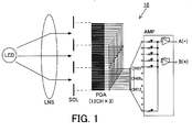
- FIG. 1 is a schematic configuration diagram of an optical encoder 10 (a transmission slit encoder) in the present embodiment.
- a divergent light emitted from a point light source LED (a point source) is converted into a parallel light by a collimater lens LNS, and the parallel light illuminates a scale SCL (a grating scale) having a movable transmission slit.
- a transmitted light that transmits through the scale SCL is received by a light-receiving element array PDA (a plurality of light-receiving elements).
- the light-receiving element PDA is a light-receiving element array that collects electric power of an output of each light-receiving element for every N light-receiving elements (N is an integer equal to or greater than 6, and N is equal to 12 in the present embodiment), and one pitch of the light-receiving element array PDA corresponds to one cycle of the light-and-dark distribution light.
- the light-receiving element array PDA is divided into N light-receiving elements (N is equal to 12 in the present embodiment) for the transmitted light (that does not have a sine wave shape) of one light-and-dark cycle. Furthermore, the light-receiving element array PDA is configured so that a phase of a periodic signal outputted from each light-receiving element is different by 360 degrees/N from each other (30 degrees in Fig. 1 ). Although the transmitted light of three light-and-dark cycles are received by the light-receiving element array PDA in Fig. 1 , the present embodiment is not limited to this and it may also be configured so that the transmitted light of two cycles or four cycles or more is received.
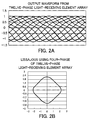
- Figs. 2A and 2B are waveform diagrams of the light-receiving element array PDA.
- Fig. 2A is an output waveform diagram (twelve-phase output waveforms) of the light-receiving element array PDA
- Fig. 2B is a Lissajous waveform diagram that is generated by using only four-phase output waveforms of the twelve-phase output waveforms of the light-receiving element array PDA.
- the output waveform of the light-receiving element array PDA does not exactly have a sine wave shape. Therefore, the Lissajous waveform generated by using only four-phase output waveforms does not exactly become a circular shape.
- An amplifier AMP of the present embodiment multiplies a first coefficient set (a first amplification factor set) whose phases are different from each other by N-phase periodic signals (N is an integer equal to or greater than 6, and N is equal to 12 in the present embodiment) obtained from the light-receiving element array PDA (multiplied by the first amplification factor set). Then, the amplifier AMP generates a first phase (A phase) periodic signal having a sine waveform based on a sum of values obtained by multiplying the first coefficient set.
- the first coefficient set with respect to the N-phase periodic signals is for example represented as follows.
- G 1 1 1 + sin 1 / N ⁇ 2 ⁇ / 2
- G 2 1 1 + sin 2 / N ⁇ 2 ⁇ / 2
- G 3 1 1 + sin 3 / N ⁇ 2 ⁇ / 2
- GN 1 1 + sin N / N ⁇ 2 ⁇ / 2
- the amplifier AMP multiplies a second coefficient set (a second amplification factor set) whose phases are different from each other by the N-phase periodic signals (multiplied by the second amplification factor set). Then, the amplifier AMP generates a second phase (B phase) periodic signal having a sine waveform based on a sum of values obtained by multiplying the second coefficient set.
- the second coefficient set with respect to the N-phase periodic signals is for example represented as follows.
- G 1 2 1 + sin 1 / N ⁇ 2 ⁇ + ⁇ / 2 / 2
- G 2 2 1 + sin 2 / N ⁇ 2 ⁇ + ⁇ / 2 / 2
- G 3 2 1 + sin 3 / N ⁇ 2 ⁇ + ⁇ / 2 / 2
- GN 2 1 + sin N / N ⁇ 2 ⁇ + ⁇ / 2 / 2
- Figs. 3A and 3B are waveform diagrams in the present embodiment.
- Fig. 3A is a waveform diagram of an A-phase and B-phase signals
- Fig. 3B is a Lissajous waveform diagram that is generated from the A-phase and B-phase signals.
- the output waveform of the amplifier AMP has a sine waveform (substantially a sine waveform)
- the Lissajous waveform that is generated based on the output waveform of the amplifier AMP has a circular shape (substantially a circular shape).
- M-phase signals (M is an integer equal to or greater than 2)
- M coefficient sets (a k-th coefficient set) are for example represented as the following general expressions.
- G 1 k 1 + sin 1 / N ⁇ 2 ⁇ + ⁇ ⁇ k ⁇ 1 / M / 2
- G 2 k 1 + sin 2 / N ⁇ 2 ⁇ + ⁇ ⁇ k ⁇ 1 / M / 2
- G 3 k 1 + sin 3 / N ⁇ 2 ⁇ + ⁇ ⁇ k ⁇ 1 / M / 2
- the amplifier AMP multiplies the M coefficient sets (the k-th coefficient set) whose phases are different from each other by N-phase periodic signals (multiplied by the k-th amplification factor set). Then, the amplifier AMP generates M-phase (k-th phase) periodic signals having sine waveforms based on a sum of values obtained by multiplying the M coefficient sets (the k-th coefficient set).
- the optical encoder 10 may include an interpolation device that performs an electric interpolation process using the M-phase periodic signals having sine waveforms.
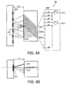
- FIGs. 4A and 4B are schematic configuration diagrams of an optical encoder 20 (a reflective slit encoder) in the present embodiment
- Fig. 4A is a front view
- Fig. 4B is a bottom view.
- the optical encoder 20 of the present embodiment obliquely illuminates a divergent light emitted from a point light source LED onto a scale SCL having a relatively-movable reflective slit that is disposed at a distance d. Then, it projects a doubled size of a light-and-dark pattern onto the light-receiving element array PDA while enlarging the reflected light.
- the light-receiving element array PDA is divided into twelve light-receiving elements with respect to one light-and-dark cycle (pitch P2, and it does not have a sine waveform), and each light-receiving element is disposed so that phases of output signals are different by 30 degrees from each other.
- a distortion component having 0.5th order of the light-and-dark signal can be effectively removed.
- the light-receiving element array PDA is configured so as to receive the reflected light of six cycles or twelve cycles that are even cycles.
- the signal outputted from the light-receiving element array PDA is similar to the waveform illustrated in Fig. 2A .
- Each of the output signals (twelve-phase signals CH01, CH02, CH03, ..., CH12) is added by two pairs of amplifiers AMP with a weight of the amplification factor of the sine wave or the cosine wave to be outputted as the A-phase signal and the B-phase signal.
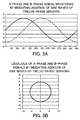
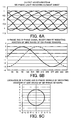
- FIG. 5 is a schematic configuration diagram of an optical encoder 30 (a transmission slit encoder) in the present embodiment.
- the optical encoder 30 of the present embodiment converts a divergent light emitted from a point light source LED into a parallel light using a collimater lens LNS, and illuminates the parallel light onto a scale SCL having a relatively-movable transmission slit to receive a transmitted light of the scale using the light-receiving element array PDA.
- N is equal to 6 in the present embodiment
- 360 degrees/6 60 degrees
- Fig. 6A is an output waveform diagram (six-phase output waveform) of the light-receiving element array PDA.
- the output waveform of the light-receiving element array PDA is not exactly a sine wave shape. Therefore, the amplifier AMP of the present embodiment multiplies a first coefficient set (a first amplification factor set) whose phases are different from each other by N-phase periodic signals (N is equal to 6 in the present embodiment) obtained from the light-receiving element array PDA (multiplied by the first amplification factor set). Then, the amplifier AMP generates a first phase (A phase) periodic signal having a sine wave shape based on a sum of values obtained by multiplying the first coefficient set.
- a first coefficient set a first amplification factor set
- N is equal to 6 in the present embodiment
- the first coefficient set with respect to the N-phase periodic signals is for example represented as follows.
- G 1 1 1 + sin 1 / 6 ⁇ 2 ⁇ / 2
- G 2 1 1 + sin 2 / 6 ⁇ 2 ⁇ / 2
- G 3 1 1 + sin 3 / 6 ⁇ 2 ⁇ / 2
- G 6 1 1 + sin 6 / 6 ⁇ 2 ⁇ / 2
- the amplifier AMP multiplies a second coefficient set (a second amplification factor set) whose phases are different from each other by the N-phase periodic signals (multiplied by the second amplification factor set). Then, the amplifier AMP generates a second phase (B phase) periodic signal having a sine wave shape based on a sum of values obtained by multiplying the second coefficient set.
- the second coefficient set with respect to the N-phase periodic signals is for example represented as follows.
- G 1 2 1 + sin 1 / 6 ⁇ 2 ⁇ + ⁇ / 2 / 2
- G 2 2 1 + sin 2 / 6 ⁇ 2 ⁇ + ⁇ / 2 / 2
- G 3 2 1 + sin 3 / 6 ⁇ 2 ⁇ + ⁇ / 2 / 2
- G 6 2 1 + sin 6 / 6 ⁇ 2 ⁇ + ⁇ / 2 / 2
- Fig. 6B is a waveform diagram of A-phase and B-phase signals
- Fig. 6C is a diagram of a Lissajous waveform that is generated from the A-phase and B-phase signals.
- the output waveform of the amplifier AMP has a sine wave shape (substantially a sine wave shape)
- the Lissajous waveform that is generated based on the output waveform of the amplifier AMP has a circular shape (substantially a circular shape).
- the present embodiment uses two-phase signals of the A-phase signal and the B-phase signal, it is not limited to this and may also use three-phase signals or more as described in the first embodiment.
- FIG. 7 is a schematic configuration diagram of an optical encoder 40 (an interference fringe projection encoder) in the present embodiment.
- the principle of this optical system is disclosed in Japanese Patent Laid-Open No. H08-226804 .
- the optical system adopts a method of generating a light-and-dark pattern having a pitch that is half of a pitch of a concavo-convex grating in a specific space by a light transmitting through a scale having the concavo-convex grating to detect it using a light-receiving element array.
- the optical encoder 40 of the present embodiment is provided with six six-phase light-receiving element arrays PDA, each of which is positioned at 1/2 pitch of the light-and-dark pattern, and adds output signals of the six light-receiving element arrays PDA.
- the six-phase signals CH1, CH2, CH3, ..., CH6 are added after being weighted by a gain (an amplification factor) of a sine wave shape or a cosine wave shape using respective two pairs of amplifiers AMP in accordance with the same method as that of the above embodiment, and then they are outputted as A-phase and B-phase signals.
- the configuration of the present embodiment is particularly effective. Furthermore, the present embodiment can be widely applied to a Talbot interference fringe projection type encoder or an encoder optical system adopting a method of projecting a deformed light-and-dark pattern onto a light-receiving element array, instead of the concavo-convex grating.
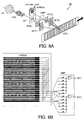
- Figs. 8A and 8B are configuration diagrams of an optical encoder 50 (a diffraction interference encoder) in the present embodiment, and specifically, Fig. 8A is an overall configuration diagram of the optical encoder and Fig. 8B is a diagram of a detail of a light-receiving element array AMP along with an explanation of the weight addition of signals.
- the optical encoder 50 generates two-phase or four-phase phase difference signal lights by the interference of ⁇ 1st-order diffracted lights generated by a scale diffraction grating using an optical unit and by providing a polarization difference in realizing uniform interference light of so-called one color (a mono color). Then, the generated phase difference signal light is received by the two-phase or four-phase light-receiving element array PDA.
- the lights combined at the same axis having linear polarizing axes different by 90 degrees from each other they are circular polarized lights whose polarization planes rotate in opposite directions different from each other after transmitting through a quarter-wave plate QWP, and they are converted into a single linear polarized light by performing a composition of vectors.
- the single linear polarized light has a characteristic that its linear polarization plane rotates by half while the diffraction grating GT3 on the relatively-movable scale moves by one pitch.
- the light-receiving element array PDA has 660 light-receiving surfaces each having a reed shape of a width of 12 ⁇ m and a length of 2000 ⁇ m at 15 ⁇ m intervals, and is configured to be electrically connected with electrodes each of which is common for the six light-receiving surfaces so as to output six channel photocurrents.
- 660 polarization element patterns such as wire grid polarization elements are arrayed in a region of a reed shape having a width of 12 ⁇ m and a length of 2000 ⁇ m at 15 ⁇ m intervals. Furthermore, a six-channel polarization element array plate that is formed by changing grating directions of the wire grid polarization plate into 0, 30, 60, 90, 120, and 150 degrees for every six patterns is inserted, and it is combined so as to overlap with each region having the reed shape of the light-receiving element array. In the present embodiment, it is referred to as a "six-channel polarization light-receiving unit 6PPDA".
- the linear polarized light that changes the direction of the polarization plane in accordance with the movement of the scale is obtained by the grating interference encoder optical system described above to enter the six-channel polarization light-receiving unit 6PPDA, it is illuminated as a substantially-uniform linear polarized light in which a direction of the linear polarization rotates along with the movement of the scale. Therefore, six-phase sine wave signals (in which a distortion has been slightly added) are obtained from output terminals.
- These six-phase signals ch1, ch2, ch3, ..., ch6 are added after being weighted by a gain of a sine wave shape or a cosine wave shape using respective two pairs of amplifiers AMP, and they are outputted as A-phase and B-phase signals. In the configuration, the distortion contained in the original signal is removed.
- the 6-phase signals can also be configured by arranging a plurality of light-receiving elements instead of the light-receiving element array PDA.
- the light-receiving element array PDA can also be configured so as to output eight-phase signals instead of the six-phase signals.
- adjacent polarizing transmission axes of the polarization element array in front of the light-receiving element array PDA may be different by 22.5 degrees from each other and electric power may be collected to electrodes for every eight channels.
- These eight-phase channels ch1, ch2, ch3, ..., ch8 are added after being weighted by a gain of a sine wave shape or a cosine wave shape using respective two pairs of amplifiers AMP, and they are outputted as A-phase and B-phase signals. It is particularly effective because distortions of 0.5th, 2th, and 4th order components easily appear in the grating interference method.
- the configuration of a slit transmission/reflection encoder having a system of detecting a plurality of phase difference signals to combine the two phases in each embodiment can realize a high-precision encoder that does not generate a distortion of a sine wave signal even if for example the position of the scale changes and the gap varies. If it is applied to a laser interferometer or a grating interference encoder, the generation of the measurement error caused by the variation of the sine wave distortion in accordance with the variation of a stray light state caused by a position change of a mirror or a scale is prevented, and therefore a high-precision interference measurement apparatus can be provided.
- the interference measurement apparatus includes a light-receiving element array PDA that performs a photoelectric conversion of an interference signal obtained by the interference of a reflected light or a transmitted light of a light illuminated onto movable reflecting surface or transmissive object and another light to generate N-phase periodic signals whose phase differences are different from each other.
- a light-receiving element array PDA that performs a photoelectric conversion of an interference signal obtained by the interference of a reflected light or a transmitted light of a light illuminated onto movable reflecting surface or transmissive object and another light to generate N-phase periodic signals whose phase differences are different from each other.
- a unit that performs an addition along with weighting the gain of the sine wave shape or the cosine wave shape may also be realized by a digital processing circuit having the same function instead of an operational amplifier.
- the present invention can also be applied to a two-phase signal generation unit with a low distortion in a Michelson laser interference measurement apparatus or a common interference optical apparatus. the generated N-phase signals by M coefficient sets that are different from each other (M is an integer not smaller than 2), respectively, and to obtain a sum of the multiplied values with respect to each of the M coefficient sets to generate M-phase signals.
Landscapes
- Physics & Mathematics (AREA)
- General Physics & Mathematics (AREA)
- Optical Transform (AREA)
- Instruments For Measurement Of Length By Optical Means (AREA)
- Length Measuring Devices By Optical Means (AREA)
Applications Claiming Priority (1)
| Application Number | Priority Date | Filing Date | Title |
|---|---|---|---|
| JP2010052652A JP5562077B2 (ja) | 2010-03-10 | 2010-03-10 | 光学式エンコーダ、エンコーダ、干渉計測装置、計測方法 |
Publications (2)
| Publication Number | Publication Date |
|---|---|
| EP2369303A1 EP2369303A1 (en) | 2011-09-28 |
| EP2369303B1 true EP2369303B1 (en) | 2016-11-23 |
Family
ID=44276111
Family Applications (1)
| Application Number | Title | Priority Date | Filing Date |
|---|---|---|---|
| EP11157257.4A Not-in-force EP2369303B1 (en) | 2010-03-10 | 2011-03-08 | Optical encoder |
Country Status (3)
| Country | Link |
|---|---|
| US (1) | US8742322B2 (enExample) |
| EP (1) | EP2369303B1 (enExample) |
| JP (1) | JP5562077B2 (enExample) |
Families Citing this family (10)
| Publication number | Priority date | Publication date | Assignee | Title |
|---|---|---|---|---|
| JP5984364B2 (ja) * | 2011-11-22 | 2016-09-06 | キヤノン株式会社 | 光学式エンコーダおよびこれを備えた装置 |
| KR101361625B1 (ko) * | 2012-06-11 | 2014-02-12 | 한국표준과학연구원 | 위치 측정 장치 및 위치 측정 방법 |
| JP5964162B2 (ja) * | 2012-07-18 | 2016-08-03 | 株式会社ミツトヨ | エンコーダ |
| JP6003372B2 (ja) * | 2012-08-07 | 2016-10-05 | 富士通株式会社 | 光学式ロータリーエンコーダ及びその補正方法 |
| JP2015041648A (ja) * | 2013-08-20 | 2015-03-02 | 株式会社東芝 | パターン形成方法、パターン形成用マスク及びパターン形成装置 |
| JP6247050B2 (ja) * | 2013-08-28 | 2017-12-13 | Necプラットフォームズ株式会社 | 情報処理装置、及び、位置検出方法 |
| JP6138664B2 (ja) * | 2013-10-30 | 2017-05-31 | オークマ株式会社 | 光学式エンコーダ |
| JP6369042B2 (ja) | 2013-11-05 | 2018-08-08 | 日本精工株式会社 | 光学式エンコーダユニット及び光学式エンコーダ |
| US10312837B2 (en) * | 2016-05-02 | 2019-06-04 | Canon Kabushiki Kaisha | Information processing apparatus, and recording medium storing computer program |
| JP7203556B2 (ja) | 2018-10-11 | 2023-01-13 | オルガノ株式会社 | 非水電解液の製造装置および非水電解液の製造方法 |
Citations (2)
| Publication number | Priority date | Publication date | Assignee | Title |
|---|---|---|---|---|
| EP0455983A1 (en) * | 1990-05-08 | 1991-11-13 | THE WARNER & SWASEY COMPANY | Position measuring device with a phase adjust circuit and process for phase adjustment |
| US6528783B1 (en) * | 1998-12-17 | 2003-03-04 | Bishop Innovation Limited | Position sensor and circuit for optical encoder |
Family Cites Families (10)
| Publication number | Priority date | Publication date | Assignee | Title |
|---|---|---|---|---|
| DE3239108A1 (de) * | 1982-10-22 | 1984-04-26 | Dr. Johannes Heidenhain Gmbh, 8225 Traunreut | Positionsmessverfahren und einrichtungen zur durchfuehrung des verfahrens |
| JPS63157016A (ja) * | 1986-12-22 | 1988-06-30 | Yokogawa Electric Corp | 光学式変位測定装置 |
| JPH03128418A (ja) * | 1989-07-20 | 1991-05-31 | Yokogawa Electric Corp | 光学式エンコーダ |
| US5572019A (en) * | 1991-03-12 | 1996-11-05 | Canon Kabushiki Kaisha | Encoder with varying width light receiver and apparatus having the encoder |
| DE4338680C1 (de) * | 1993-11-12 | 1995-03-23 | Heidenhain Gmbh Dr Johannes | Längen- oder Winkelmeßeinrichtung |
| JPH08226804A (ja) | 1995-02-21 | 1996-09-03 | Canon Inc | 変位情報検出装置及びこれを用いたドライブ制御装置 |
| US6803560B1 (en) * | 1999-06-10 | 2004-10-12 | Canon Kabushiki Kaisha | Optical encoder |
| WO2003021197A1 (en) * | 2001-08-30 | 2003-03-13 | Microe Systems Corporation | Harmonic suppressing photodetector array |
| JP2003279382A (ja) * | 2002-03-20 | 2003-10-02 | Mitsutoyo Corp | 光電式エンコーダ |
| JP4291168B2 (ja) * | 2004-01-21 | 2009-07-08 | オリンパス株式会社 | 光学式エンコーダ用光検出器 |
-
2010
- 2010-03-10 JP JP2010052652A patent/JP5562077B2/ja not_active Expired - Fee Related
-
2011
- 2011-03-02 US US13/038,597 patent/US8742322B2/en not_active Expired - Fee Related
- 2011-03-08 EP EP11157257.4A patent/EP2369303B1/en not_active Not-in-force
Patent Citations (2)
| Publication number | Priority date | Publication date | Assignee | Title |
|---|---|---|---|---|
| EP0455983A1 (en) * | 1990-05-08 | 1991-11-13 | THE WARNER & SWASEY COMPANY | Position measuring device with a phase adjust circuit and process for phase adjustment |
| US6528783B1 (en) * | 1998-12-17 | 2003-03-04 | Bishop Innovation Limited | Position sensor and circuit for optical encoder |
Also Published As
| Publication number | Publication date |
|---|---|
| EP2369303A1 (en) | 2011-09-28 |
| US8742322B2 (en) | 2014-06-03 |
| JP5562077B2 (ja) | 2014-07-30 |
| JP2011185810A (ja) | 2011-09-22 |
| US20110220780A1 (en) | 2011-09-15 |
Similar Documents
| Publication | Publication Date | Title |
|---|---|---|
| EP2369303B1 (en) | Optical encoder | |
| KR101184129B1 (ko) | 광학식 인코더 | |
| US5889280A (en) | Apparatus for measuring displacement | |
| JP3209914B2 (ja) | 光学式エンコーダ | |
| JP5887064B2 (ja) | 光学式エンコーダ | |
| KR101240413B1 (ko) | 원점 검출 장치, 변위 측정 장치 및 광학 장치 | |
| US8860949B2 (en) | Interferometer | |
| JP5479255B2 (ja) | 光学式エンコーダ | |
| JPH0131127B2 (enExample) | ||
| EP2511669B1 (en) | Encoder | |
| US20070024865A1 (en) | Optical encoder having slanted optical detector elements for harmonic suppression | |
| JP2015078861A (ja) | 干渉縞走査受光モジュール、干渉計測装置、エンコーダ、および干渉型変位計測装置 | |
| JP2016085055A (ja) | 光学式エンコーダ | |
| EP2778626B1 (en) | Position detection apparatus, lens apparatus, image pickup system, machine tool apparatus, position detection method, program, and storage medium | |
| US6094307A (en) | Optical grating and encoder | |
| JP2012181098A (ja) | 光強度スペクトル測定方法および装置 | |
| JPS6363916A (ja) | 光学式変位検出器 | |
| US10274344B2 (en) | Displacement encoder | |
| JP5154072B2 (ja) | 光電式エンコーダ | |
| JP3199549B2 (ja) | エンコーダ装置 | |
| CN119958428B (zh) | 一种高精度光栅尺系统以及测量设备 | |
| JP7532176B2 (ja) | 光学式エンコーダ及び制御装置 | |
| US20240110816A1 (en) | Optical encoder | |
| JPH02304313A (ja) | 光学式変位計 | |
| JPH068736B2 (ja) | 光学式変位検出器 |
Legal Events
| Date | Code | Title | Description |
|---|---|---|---|
| PUAI | Public reference made under article 153(3) epc to a published international application that has entered the european phase |
Free format text: ORIGINAL CODE: 0009012 |
|
| AK | Designated contracting states |
Kind code of ref document: A1 Designated state(s): AL AT BE BG CH CY CZ DE DK EE ES FI FR GB GR HR HU IE IS IT LI LT LU LV MC MK MT NL NO PL PT RO RS SE SI SK SM TR |
|
| AX | Request for extension of the european patent |
Extension state: BA ME |
|
| TPAC | Observations filed by third parties |
Free format text: ORIGINAL CODE: EPIDOSNTIPA |
|
| 17P | Request for examination filed |
Effective date: 20120328 |
|
| 17Q | First examination report despatched |
Effective date: 20140708 |
|
| GRAP | Despatch of communication of intention to grant a patent |
Free format text: ORIGINAL CODE: EPIDOSNIGR1 |
|
| INTG | Intention to grant announced |
Effective date: 20160608 |
|
| RIN1 | Information on inventor provided before grant (corrected) |
Inventor name: ISHIZUKA, KO |
|
| GRAS | Grant fee paid |
Free format text: ORIGINAL CODE: EPIDOSNIGR3 |
|
| GRAA | (expected) grant |
Free format text: ORIGINAL CODE: 0009210 |
|
| AK | Designated contracting states |
Kind code of ref document: B1 Designated state(s): AL AT BE BG CH CY CZ DE DK EE ES FI FR GB GR HR HU IE IS IT LI LT LU LV MC MK MT NL NO PL PT RO RS SE SI SK SM TR |
|
| REG | Reference to a national code |
Ref country code: GB Ref legal event code: FG4D |
|
| REG | Reference to a national code |
Ref country code: CH Ref legal event code: EP |
|
| REG | Reference to a national code |
Ref country code: IE Ref legal event code: FG4D |
|
| REG | Reference to a national code |
Ref country code: AT Ref legal event code: REF Ref document number: 848335 Country of ref document: AT Kind code of ref document: T Effective date: 20161215 |
|
| REG | Reference to a national code |
Ref country code: DE Ref legal event code: R096 Ref document number: 602011032620 Country of ref document: DE |
|
| PG25 | Lapsed in a contracting state [announced via postgrant information from national office to epo] |
Ref country code: LV Free format text: LAPSE BECAUSE OF FAILURE TO SUBMIT A TRANSLATION OF THE DESCRIPTION OR TO PAY THE FEE WITHIN THE PRESCRIBED TIME-LIMIT Effective date: 20161123 |
|
| REG | Reference to a national code |
Ref country code: LT Ref legal event code: MG4D |
|
| REG | Reference to a national code |
Ref country code: NL Ref legal event code: MP Effective date: 20161123 |
|
| REG | Reference to a national code |
Ref country code: AT Ref legal event code: MK05 Ref document number: 848335 Country of ref document: AT Kind code of ref document: T Effective date: 20161123 |
|
| PG25 | Lapsed in a contracting state [announced via postgrant information from national office to epo] |
Ref country code: NL Free format text: LAPSE BECAUSE OF FAILURE TO SUBMIT A TRANSLATION OF THE DESCRIPTION OR TO PAY THE FEE WITHIN THE PRESCRIBED TIME-LIMIT Effective date: 20161123 Ref country code: SE Free format text: LAPSE BECAUSE OF FAILURE TO SUBMIT A TRANSLATION OF THE DESCRIPTION OR TO PAY THE FEE WITHIN THE PRESCRIBED TIME-LIMIT Effective date: 20161123 Ref country code: NO Free format text: LAPSE BECAUSE OF FAILURE TO SUBMIT A TRANSLATION OF THE DESCRIPTION OR TO PAY THE FEE WITHIN THE PRESCRIBED TIME-LIMIT Effective date: 20170223 Ref country code: LT Free format text: LAPSE BECAUSE OF FAILURE TO SUBMIT A TRANSLATION OF THE DESCRIPTION OR TO PAY THE FEE WITHIN THE PRESCRIBED TIME-LIMIT Effective date: 20161123 Ref country code: GR Free format text: LAPSE BECAUSE OF FAILURE TO SUBMIT A TRANSLATION OF THE DESCRIPTION OR TO PAY THE FEE WITHIN THE PRESCRIBED TIME-LIMIT Effective date: 20170224 |
|
| PG25 | Lapsed in a contracting state [announced via postgrant information from national office to epo] |
Ref country code: RS Free format text: LAPSE BECAUSE OF FAILURE TO SUBMIT A TRANSLATION OF THE DESCRIPTION OR TO PAY THE FEE WITHIN THE PRESCRIBED TIME-LIMIT Effective date: 20161123 Ref country code: AT Free format text: LAPSE BECAUSE OF FAILURE TO SUBMIT A TRANSLATION OF THE DESCRIPTION OR TO PAY THE FEE WITHIN THE PRESCRIBED TIME-LIMIT Effective date: 20161123 Ref country code: PT Free format text: LAPSE BECAUSE OF FAILURE TO SUBMIT A TRANSLATION OF THE DESCRIPTION OR TO PAY THE FEE WITHIN THE PRESCRIBED TIME-LIMIT Effective date: 20170323 Ref country code: HR Free format text: LAPSE BECAUSE OF FAILURE TO SUBMIT A TRANSLATION OF THE DESCRIPTION OR TO PAY THE FEE WITHIN THE PRESCRIBED TIME-LIMIT Effective date: 20161123 Ref country code: ES Free format text: LAPSE BECAUSE OF FAILURE TO SUBMIT A TRANSLATION OF THE DESCRIPTION OR TO PAY THE FEE WITHIN THE PRESCRIBED TIME-LIMIT Effective date: 20161123 Ref country code: PL Free format text: LAPSE BECAUSE OF FAILURE TO SUBMIT A TRANSLATION OF THE DESCRIPTION OR TO PAY THE FEE WITHIN THE PRESCRIBED TIME-LIMIT Effective date: 20161123 Ref country code: FI Free format text: LAPSE BECAUSE OF FAILURE TO SUBMIT A TRANSLATION OF THE DESCRIPTION OR TO PAY THE FEE WITHIN THE PRESCRIBED TIME-LIMIT Effective date: 20161123 |
|
| PG25 | Lapsed in a contracting state [announced via postgrant information from national office to epo] |
Ref country code: CZ Free format text: LAPSE BECAUSE OF FAILURE TO SUBMIT A TRANSLATION OF THE DESCRIPTION OR TO PAY THE FEE WITHIN THE PRESCRIBED TIME-LIMIT Effective date: 20161123 Ref country code: DK Free format text: LAPSE BECAUSE OF FAILURE TO SUBMIT A TRANSLATION OF THE DESCRIPTION OR TO PAY THE FEE WITHIN THE PRESCRIBED TIME-LIMIT Effective date: 20161123 Ref country code: RO Free format text: LAPSE BECAUSE OF FAILURE TO SUBMIT A TRANSLATION OF THE DESCRIPTION OR TO PAY THE FEE WITHIN THE PRESCRIBED TIME-LIMIT Effective date: 20161123 Ref country code: EE Free format text: LAPSE BECAUSE OF FAILURE TO SUBMIT A TRANSLATION OF THE DESCRIPTION OR TO PAY THE FEE WITHIN THE PRESCRIBED TIME-LIMIT Effective date: 20161123 Ref country code: SK Free format text: LAPSE BECAUSE OF FAILURE TO SUBMIT A TRANSLATION OF THE DESCRIPTION OR TO PAY THE FEE WITHIN THE PRESCRIBED TIME-LIMIT Effective date: 20161123 |
|
| REG | Reference to a national code |
Ref country code: DE Ref legal event code: R097 Ref document number: 602011032620 Country of ref document: DE |
|
| PG25 | Lapsed in a contracting state [announced via postgrant information from national office to epo] |
Ref country code: SM Free format text: LAPSE BECAUSE OF FAILURE TO SUBMIT A TRANSLATION OF THE DESCRIPTION OR TO PAY THE FEE WITHIN THE PRESCRIBED TIME-LIMIT Effective date: 20161123 Ref country code: BE Free format text: LAPSE BECAUSE OF FAILURE TO SUBMIT A TRANSLATION OF THE DESCRIPTION OR TO PAY THE FEE WITHIN THE PRESCRIBED TIME-LIMIT Effective date: 20161123 Ref country code: IT Free format text: LAPSE BECAUSE OF FAILURE TO SUBMIT A TRANSLATION OF THE DESCRIPTION OR TO PAY THE FEE WITHIN THE PRESCRIBED TIME-LIMIT Effective date: 20161123 Ref country code: BG Free format text: LAPSE BECAUSE OF FAILURE TO SUBMIT A TRANSLATION OF THE DESCRIPTION OR TO PAY THE FEE WITHIN THE PRESCRIBED TIME-LIMIT Effective date: 20170223 |
|
| PLBE | No opposition filed within time limit |
Free format text: ORIGINAL CODE: 0009261 |
|
| STAA | Information on the status of an ep patent application or granted ep patent |
Free format text: STATUS: NO OPPOSITION FILED WITHIN TIME LIMIT |
|
| REG | Reference to a national code |
Ref country code: CH Ref legal event code: PL |
|
| 26N | No opposition filed |
Effective date: 20170824 |
|
| GBPC | Gb: european patent ceased through non-payment of renewal fee |
Effective date: 20170308 |
|
| PG25 | Lapsed in a contracting state [announced via postgrant information from national office to epo] |
Ref country code: SI Free format text: LAPSE BECAUSE OF FAILURE TO SUBMIT A TRANSLATION OF THE DESCRIPTION OR TO PAY THE FEE WITHIN THE PRESCRIBED TIME-LIMIT Effective date: 20161123 Ref country code: MC Free format text: LAPSE BECAUSE OF FAILURE TO SUBMIT A TRANSLATION OF THE DESCRIPTION OR TO PAY THE FEE WITHIN THE PRESCRIBED TIME-LIMIT Effective date: 20161123 |
|
| REG | Reference to a national code |
Ref country code: IE Ref legal event code: MM4A |
|
| REG | Reference to a national code |
Ref country code: FR Ref legal event code: ST Effective date: 20171130 |
|
| PG25 | Lapsed in a contracting state [announced via postgrant information from national office to epo] |
Ref country code: FR Free format text: LAPSE BECAUSE OF NON-PAYMENT OF DUE FEES Effective date: 20170331 Ref country code: LU Free format text: LAPSE BECAUSE OF NON-PAYMENT OF DUE FEES Effective date: 20170308 |
|
| PG25 | Lapsed in a contracting state [announced via postgrant information from national office to epo] |
Ref country code: IE Free format text: LAPSE BECAUSE OF NON-PAYMENT OF DUE FEES Effective date: 20170308 Ref country code: LI Free format text: LAPSE BECAUSE OF NON-PAYMENT OF DUE FEES Effective date: 20170331 Ref country code: GB Free format text: LAPSE BECAUSE OF NON-PAYMENT OF DUE FEES Effective date: 20170308 Ref country code: CH Free format text: LAPSE BECAUSE OF NON-PAYMENT OF DUE FEES Effective date: 20170331 |
|
| PG25 | Lapsed in a contracting state [announced via postgrant information from national office to epo] |
Ref country code: MT Free format text: LAPSE BECAUSE OF NON-PAYMENT OF DUE FEES Effective date: 20170308 |
|
| PG25 | Lapsed in a contracting state [announced via postgrant information from national office to epo] |
Ref country code: HU Free format text: LAPSE BECAUSE OF FAILURE TO SUBMIT A TRANSLATION OF THE DESCRIPTION OR TO PAY THE FEE WITHIN THE PRESCRIBED TIME-LIMIT; INVALID AB INITIO Effective date: 20110308 |
|
| PG25 | Lapsed in a contracting state [announced via postgrant information from national office to epo] |
Ref country code: CY Free format text: LAPSE BECAUSE OF NON-PAYMENT OF DUE FEES Effective date: 20161123 |
|
| PG25 | Lapsed in a contracting state [announced via postgrant information from national office to epo] |
Ref country code: MK Free format text: LAPSE BECAUSE OF FAILURE TO SUBMIT A TRANSLATION OF THE DESCRIPTION OR TO PAY THE FEE WITHIN THE PRESCRIBED TIME-LIMIT Effective date: 20161123 |
|
| PG25 | Lapsed in a contracting state [announced via postgrant information from national office to epo] |
Ref country code: TR Free format text: LAPSE BECAUSE OF FAILURE TO SUBMIT A TRANSLATION OF THE DESCRIPTION OR TO PAY THE FEE WITHIN THE PRESCRIBED TIME-LIMIT Effective date: 20161123 |
|
| PG25 | Lapsed in a contracting state [announced via postgrant information from national office to epo] |
Ref country code: AL Free format text: LAPSE BECAUSE OF FAILURE TO SUBMIT A TRANSLATION OF THE DESCRIPTION OR TO PAY THE FEE WITHIN THE PRESCRIBED TIME-LIMIT Effective date: 20161123 Ref country code: IS Free format text: LAPSE BECAUSE OF FAILURE TO SUBMIT A TRANSLATION OF THE DESCRIPTION OR TO PAY THE FEE WITHIN THE PRESCRIBED TIME-LIMIT Effective date: 20170323 |
|
| PGFP | Annual fee paid to national office [announced via postgrant information from national office to epo] |
Ref country code: DE Payment date: 20200528 Year of fee payment: 10 |
|
| REG | Reference to a national code |
Ref country code: DE Ref legal event code: R119 Ref document number: 602011032620 Country of ref document: DE |
|
| PG25 | Lapsed in a contracting state [announced via postgrant information from national office to epo] |
Ref country code: DE Free format text: LAPSE BECAUSE OF NON-PAYMENT OF DUE FEES Effective date: 20211001 |