EP2368474B1 - Vorrichtung zur Anordnung und Halterung eines Filterbeutels - Google Patents
Vorrichtung zur Anordnung und Halterung eines Filterbeutels Download PDFInfo
- Publication number
- EP2368474B1 EP2368474B1 EP11400005.2A EP11400005A EP2368474B1 EP 2368474 B1 EP2368474 B1 EP 2368474B1 EP 11400005 A EP11400005 A EP 11400005A EP 2368474 B1 EP2368474 B1 EP 2368474B1
- Authority
- EP
- European Patent Office
- Prior art keywords
- filter
- filter housing
- holding
- holding plate
- receptacles
- Prior art date
- Legal status (The legal status is an assumption and is not a legal conclusion. Google has not performed a legal analysis and makes no representation as to the accuracy of the status listed.)
- Active
Links
- 239000000945 filler Substances 0.000 description 7
- 238000003780 insertion Methods 0.000 description 3
- 230000037431 insertion Effects 0.000 description 3
- 230000000903 blocking effect Effects 0.000 description 1
- 230000007547 defect Effects 0.000 description 1
- 238000010586 diagram Methods 0.000 description 1
- 239000000428 dust Substances 0.000 description 1
- 238000000034 method Methods 0.000 description 1
Images

Classifications
-
- A—HUMAN NECESSITIES
- A47—FURNITURE; DOMESTIC ARTICLES OR APPLIANCES; COFFEE MILLS; SPICE MILLS; SUCTION CLEANERS IN GENERAL
- A47L—DOMESTIC WASHING OR CLEANING; SUCTION CLEANERS IN GENERAL
- A47L9/00—Details or accessories of suction cleaners, e.g. mechanical means for controlling the suction or for effecting pulsating action; Storing devices specially adapted to suction cleaners or parts thereof; Carrying-vehicles specially adapted for suction cleaners
- A47L9/10—Filters; Dust separators; Dust removal; Automatic exchange of filters
- A47L9/14—Bags or the like; Rigid filtering receptacles; Attachment of, or closures for, bags or receptacles
- A47L9/1427—Means for mounting or attaching bags or filtering receptacles in suction cleaners; Adapters
- A47L9/1436—Connecting plates, e.g. collars, end closures
Definitions
- the invention relates to a vacuum cleaner with a holder of a filter bag in a filter housing, wherein the filter bag is provided with a stiffening element in the form of a filter plate having a filling opening and the filter plate is insertable into corresponding receptacles of the filter housing and a filler neck on the lid of the filter housing engages in the filling opening with a seal when closing, wherein the filter retaining plate is approximately vertically inserted into a fastening element for fixing in the filter housing.
- Arrangements of this type are known in different configurations, wherein a filter retaining plate of a filter bag is received in a defined holding position.
- the object of the invention is to provide a simple holder of the filter plate in the filter housing, which ensures a user-friendly handling and ensures a dust-insensitive storage.
- a lug-shaped fastener in the end has holding elements in corresponding receptacles on the filter housing by pivoting the filter plate for inserting the filter bag in the filter housing as a use position an outer edge region of the fastener by an overlapping abutment in the position of use before intervention of the filler neck is fixed to the filter housing.
- the holding elements are designed as approximately semicircular shaped guide members which are insertable and pivotable in corresponding trough-shaped receptacles on the filter housing, wherein the outer edge region of the fastening element engages under a projecting abutment on the filter housing.
- the holding element has two parallel spaced guide members, which are associated with corresponding receptacles and webs form the outer edge region, which serve for mounting on the abutment of the filter housing.
- a pivotable projecting locking element for the attachable lid is arranged, which cooperates with a protruding element on the lockable lid and the blocking element via a assigned edge on the fastening element of the filter retaining plate in a position of use of the filter bag used a pivoted position outside the element on the lid is adjustable.
- the retaining element has slots which engage in the pivoted position of the fastening element of the filter retaining plate in associated receiving elements on the filter housing.
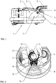
- the illustrated vacuum cleaner 1 shows a filter housing 2 with a filter bag 3 inserted, which can be inserted into the filter housing 2 via a filter holding plate 4.
- the filter housing 2 can be closed by a hinged lid 5, which has a filler neck 8 for a hose connection 9.
- the inserted filter holding plate 4 of the filter bag 3 has a filling opening 10 and a seal 21, wherein in the filling opening 10 of the filler neck 8 engages when closing the lid 5.
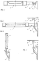
- the filter holding plate 4 has a lug-shaped fastening element 11, which has two parallel holding elements 12 in the end region.
- the holding elements 12 are formed by formed below the filter plate 4 semi-circular bulges.
- the holding elements 12 are used as semicircular bulges in corresponding trough-shaped receptacles 13 on the filter housing 2 and the filter plate 4 in a position of use pivoted.
- arranged in the outer region of the holding elements 12 webs 14 are held below a formed abutment 15 on the filter housing 2.
- the filter holder plate 4 is operatively disposed in the filter housing 2 and the lid 5 is closed in a known manner.
- a pivotable securing element 16 As a backup for the lid 5 without inserted filter bag 3 is provided to arrange a pivotable securing element 16 as a bracket, which is arranged vertically in the normal position and prevents the closing of the lid 5 by an associated protruding element 17.
- the securing element 16 When inserting the filter retaining plate 4 into the filter housing 2, the securing element 16 is pivoted by an edge 18 on the retaining element 12 and assumes a position next to the element 17 when the cover 5 is closed.
- the holding element 12 has slots 19, which are assigned after pivoting the filter holding plate 4 in associated receiving elements 20 on the filter housing 2.
Landscapes
- Engineering & Computer Science (AREA)
- Mechanical Engineering (AREA)
- Filters For Electric Vacuum Cleaners (AREA)
Description
- Die Erfindung bezieht sich auf einen Staubsauger mit einer Halterung eines Filterbeutels in einem Filtergehäuse, wobei der Filterbeutel mit einem Versteifungselement in Form einer Filterhalteplatte versehen ist, die eine Einfüllöffnung aufweist und die Filterhalteplatte in korrespondierende Aufnahmen des Filtergehäuses einsetzbar ist sowie ein Einfüllstutzen am Deckel des Filtergehäuses in die Einfüllöffnung mit einer Dichtung beim Verschliessen eingreift, wobei die Filterhalteplatte etwa vertikal in ein Befestigungselement zur Festlegung im Filtergehäuse einsetzbar ist.
- Anordnungen dieser Art sind in unterschiedlichen Ausbildungen bekannt, wobei eine Filterhalteplatte einer Filtertüte in einer definierten Halteposition aufgenommen wird. Insbesondere ist es bekannt, die Filterhalteplatte in Schiebeführungen anzuordnen, die aber eine relativ genaue Einfädelung erfordern und auch staubanfällig sind.
- Eine Anordnung dieser Art ist nach der
DE 88 03 516 U1 bekannt geworden. Hierbei besteht der Mangel, dass die Filterhalteplatte des Filterbeutels sich nach dem Einsetzen nicht in einer festgelegten Gebrauchsposition als Arbeitsposition befindet. Es wird vielmehr eine Position durch einen verschwenkbaren Deckel mit dem Einfüllstutzen vorgenommen. - Weiterhin ist nach der
DE 10 2008 041 227 A1 eine weitere Anordnung mit einer verschwenkbaren Filterhalteplatte des Filterbeutels über eine Gelenkanordnung bekannt. Hierbei ist eine definierte Gebrauchsposition der Filterhalteplatte nicht gegeben und die Zuordnung des Einfüllstutzens über den verschwenkbaren Deckel ist nicht definiert. - Die Aufgabe der Erfindung ist es, eine einfache Halterung der Filterhalteplatte im Filtergehäuse zu schaffen, die eine bedienerfreundliche Handhabung gewährleistet und eine staubunempfindliche Lagerung gewährleistet.
- Die Lösung dieser Aufgabe erfolgt erfindungsgemäss dadurch, dass ein laschenförmiges Befestigungselement im Endbereich Halteelemente besitzt, die in korrespondierende Aufnahmen am Filtergehäuse durch Verschwenken der Filterhalteplatte zum Einlegen des Filterbeutels in das Filtergehäuse als Gebrauchsposition ein aussenliegender Randbereich des Befestigungselementes durch ein übergreifendes Gegenlager in der Gebrauchsposition vor Eingreifen des Einfüllstutzens am Filtergehäuse festgelegt ist.
- Hierdurch wird eine einfache problemlose Auswechselung der Filtertüte ermöglicht, wobei eine Ausrichtung und Halterung der Filtertüte ausschliesslich über das Befestigungselement erfolgt. Dabei werden die ansonsten üblichen Bauteile nicht benötigt und es sind relativ grosse Toleranzen für die zugeordneten Elemente möglich.
- Eine vorteilhafte Ausgestaltung wird dadurch geschaffen, dass die Halteelemente als etwa halbkreisförmig ausgeformte Führungsglieder ausgebildet sind, die in korrespondierende muldenförmige Aufnahmen am Filtergehäuse einsetzbar und verschwenkbar sind, wobei der aussenliegende Randbereich des Befestigungselementes unter ein vorstehendes Gegenlager am Filtergehäuse greift.
- Ferner ist vorgesehen, dass das Halteelement zwei parallele im Abstand angeordnete Führungsglieder aufweist, die korrespondierenden Aufnahmen zugeordnet sind und Stege den äusseren Randbereich bilden, die zur Halterung am Gegenlager des Filtergehäuses dienen.
- Zur Vermeidung eines Verschlusses des Deckels ohne eingesetzte Filtertüte wird vorgeschlagen, dass im Bereich der Aufnahmen im Filtergehäuse zum Einsetzen der Halteelemente des Befestigungselementes ein verschwenkbares vorstehendes Sperrelement für den aufsetzbaren Deckel angeordnet ist, das mit einem vorstehenden Element am verschliessbaren Deckel zusammenwirkt und das Sperrelement über eine zugeordnete Kante am Befestigungselement der Filterhalteplatte in einer Gebrauchsposition des eingesetzten Filterbeutels eine verschwenkte Position ausserhalb des Elementes am Deckel einstellbar ist.
- Zur Verbesserung einer Fixierung der Filterhalteplatte wird vorgeschlagen, dass das Halteelement Schlitze aufweist, die in der verschwenkten Lage des Befestigungselementes der Filterhalteplatte in zugeordnete Aufnahmeelemente am Filtergehäuse eingreifen.
- In der Zeichnung ist ein Ausführungsbeispiel der Erfindung schematisch dargestellt. Es zeigen:
- Fig. 1
- eine Prinzipdarstellung eines Staubsaugers mit eingesetztem Filterbeutel;
- Fig. 2
- eine Darstellung eines Filtergehäuses mit einem Filterbeutel und einer Filterhalteplatte beim Einsetzvorgang;
- Fig. 3
- eine weitere Ansicht auf das Filtergehäuse mit Aufnahmen für Halteelemente des Befestigungselementes;
- Fig. 4
- eine Darstellung wie
Fig. 2 mit eingesetzter Filterhalteplatte; - Fig. 5
- eine Filterhalteplatte ohne Filterbeutel in einer Einsetzposition in Aufnahmen des Filtergehäuses;
- Fig. 6
- eine verschwenkte Filterhalteplatte in Gebrauchsposition mit einem Schnitt im Bereich der Aufnahme im Filtergehäuse und
- Fig. 7
- eine Darstellung gemäss
Fig. 6 mit einer anderen Schnittebene und einem zugeordneten geschlossenen Deckel mit Einfüllstutzen und - Fig. 8
- eine Aufnahme des Filtergehäuses ohne eingesetzter Filterhalteplatte mit blockiertem Deckel
- Der dargestellte Staubsauger 1 zeigt ein Filtergehäuse 2 mit einem eingesetzten Filterbeutel 3, der über eine Filterhalteplatte 4 in das Filtergehäuse 2 einsetzbar ist. Das Filtergehäuse 2 ist durch einen abklappbaren Deckel 5 verschliessbar, der einen Einfüllstutzen 8 für einen Schlauchanschluss 9 aufweist. Die eingesetzte Filterhalteplatte 4 des Filterbeutels 3 besitzt eine Einfüllöffnung 10 und eine Dichtung 21, wobei in die Einfüllöffnung 10 der Einfüllstutzen 8 beim Verschliessen des Deckels 5 eingreift.
- Zum Festsetzen der Filterhalteplatte 4 in das Filtergehäuse 2 besitzt die Filterhalteplatte 4 ein laschenförmiges Befestigungselement 11, das im Endbereich zwei parallel angeordnete Halteelemente 12 aufweist. In dieser Ausbildung sind die Halteelemente 12 durch unterhalb der Filterhalteplatte 4 ausgeformte halbkreisförmige Ausbuchtungen gebildet. Beim Einsetzen der Filterplatte 4 in etwa vertikaler Richtung werden die Halteelemente 12 als halbkreisförmige Ausbuchtungen in korrespondierende muldenförmige Aufnahmen 13 am Filtergehäuse 2 eingesetzt und die Filterhalteplatte 4 in eine Gebrauchsposition verschwenkt. Dabei werden im Aussenbereich der Halteelemente 12 angeordnete Stege 14 unterhalb eines gebildeten Gegenlagers 15 am Filtergehäuse 2 gehalten. Hierdurch ist die Filterhalteplatte 4 im Filtergehäuse 2 funktionsfähig angeordnet und der Deckel 5 in bekannter Weise geschlossen.
- Als Sicherung für den Deckel 5 ohne eingesetzten Filterbeutel 3 ist vorgesehen, ein verschwenkbares Sicherungselement 16 als Bügel anzuordnen, das in der Normallage vertikal angeordnet ist und das Schliessen des Deckels 5 durch ein zugeordnetes vorstehendes Element 17 verhindert. Beim Einsetzen der Filterhalteplatte 4 in das Filtergehäuse 2 wird durch eine Kante 18 am Halteelement 12 das Sicherungselement 16 verschwenkt und nimmt beim Schliessen des Deckels 5 eine Lage neben dem Element 17 ein.
- Zweckmässig ist es, dass das Halteelement 12 Schlitze 19 aufweist, die nach Verschwenken der Filterhalteplatte 4 in zugeordnete Aufnahmeelemente 20 am Filtergehäuse 2 zugeordnet sind.
Claims (5)
- Staubsauger mit einer Halterung eines Filterbeutels (3) in einem Filtergehäuse (2), wobei der Filterbeutel (3) mit einem Versteifungselement in Form einer Filterhalteplatte (4) versehen ist, die eine Einfüllöffnung (10) aufweist und die Filterhalteplatte (4) in korrespondierende Aufnahmen des Filtergehäuses (2) einsetzbar ist sowie ein Einfüllstutzen (8) am Deckel (5) des Filtergehäuses (2) in die Einfüllöffnung (10) mit einer Dichtung (21) beim Verschliessen eingreift, wobei die Filterhalteplatte (4) etwa vertikal in Aufnahmen (13) zur Festlegung im Filtergehäuse (2) einsetzbar ist, dadurch gekennzeichnet, dass die Filterhalteplatte (4) ein laschenförmiges Befestigungselement (11) aufweist, welches im Endbereich Halteelemente (12) besitzt, die in die korrespondierenden Aufnahmen (13) am Filtergehäuse (2) einsetzbar sind und dass durch Verschwenken der Filterhalteplatte (4) zum Einlegen des Filterbeutels (3) in das Filtergehäuse (2) als Gebrauchsposition ein aussenliegender Randbereich (14) des Befestigungselementes (11) durch ein übergreifendes Gegenlager (15) am Filtergehäuse (2) in der Gebrauchsposition vor Eingreifen des Einfüllstutzens (8) am Filtergehäuse (2) festgelegt ist.
- Vorrichtung nach Anspruch 1, dadurch gekennzeichnet, dass die Halteelemente (12) als etwa halbkreisförmig ausgeformte Führungsglieder ausgebildet sind, die in korrespondierende muldenförmige Aufnahmen (13) am Filtergehäuse (2) einsetzbar und verschwenkbar sind, wobei der aussenliegende Randbereich des Befestigungselementes (11) unter ein vorstehendes Gegenlager (15) am Filtergehäuse (2) greift.
- Vorrichtung nach Anspruch 1 oder 2, dadurch gekennzeichnet, dass das Halteelement (12) zwei parallele im Abstand angeordnete Führungsglieder aufweist, die korrespondierenden Aufnahmen (13) zugeordnet sind und Stege (14) den äusseren Randbereich bilden, die zur Halterung am Gegenlager (15) des Filtergehäuses (2) dienen.
- Vorrichtung nach einem der Ansprüche 1 bis 3, dadurch gekennzeichnet, dass im Bereich der Aufnahmen (13) im Filtergehäuse (2) zum Einsetzen der Halteelemente (12) des Befestigungselementes (11) ein verschwenkbares vorstehendes Sperrelement (16) für den aufsetzbaren Deckel (5) angeordnet ist, das mit einem vorstehenden Element (17) am verschliessbaren Deckel (5) zusammenwirkt und das Sperrelement (16) über eine zugeordnete Kante (18) des Befestigungselementes (11) der Filterhalteplatte (4) in einer Gebrauchsposition des eingesetzten Filterbeutels (3) eine verschwenkte Position ausserhalb des Elementes (17) am Deckel (5) einstellbar ist.
- Vorrichtung nach einem der Ansprüche 1 bis 4, dadurch gekennzeichnet, dass das Halteelement (14) Schlitze (19) aufweist, die in der verschwenkten Lage des Befestigungselementes (11) der Filterhalteplatte (4) in zugeordnete Aufnahmeelemente (20) am Filtergehäuse (2) eingreifen.
Applications Claiming Priority (1)
| Application Number | Priority Date | Filing Date | Title |
|---|---|---|---|
| DE102010012637A DE102010012637B8 (de) | 2010-03-23 | 2010-03-23 | Vorrichtung zur Anordnung und Halterung eines Filterbeutels |
Publications (3)
| Publication Number | Publication Date |
|---|---|
| EP2368474A2 EP2368474A2 (de) | 2011-09-28 |
| EP2368474A3 EP2368474A3 (de) | 2013-04-17 |
| EP2368474B1 true EP2368474B1 (de) | 2017-01-04 |
Family
ID=44170377
Family Applications (1)
| Application Number | Title | Priority Date | Filing Date |
|---|---|---|---|
| EP11400005.2A Active EP2368474B1 (de) | 2010-03-23 | 2011-01-07 | Vorrichtung zur Anordnung und Halterung eines Filterbeutels |
Country Status (4)
| Country | Link |
|---|---|
| US (1) | US8640302B2 (de) |
| EP (1) | EP2368474B1 (de) |
| CA (1) | CA2734653C (de) |
| DE (1) | DE102010012637B8 (de) |
Family Cites Families (9)
| Publication number | Priority date | Publication date | Assignee | Title |
|---|---|---|---|---|
| DE2649239C2 (de) * | 1976-10-29 | 1986-11-06 | Miele & Cie GmbH & Co, 4830 Gütersloh | Einrichtung zum Befestigen eines Filterbeutels an einer Staubförderleitung eines Staubsaugers |
| DE3518346A1 (de) * | 1985-05-22 | 1986-11-27 | Miele & Cie GmbH & Co, 4830 Gütersloh | Halteplatte aus kunststoff oder dergl. fuer staubsaugerfilterbeutel |
| DE8803516U1 (de) * | 1988-03-15 | 1989-07-13 | Siemens Ag, 1000 Berlin Und 8000 Muenchen | Staubsauger mit einem am Staubsaugergehäuse verschwenkbar angelenkten Deckel zum Verschließen des Staubraumes |
| JPH0584187A (ja) * | 1991-09-30 | 1993-04-06 | Matsushita Electric Ind Co Ltd | 電気掃除機 |
| DE102004046384B4 (de) * | 2004-09-24 | 2009-06-18 | Stein & Co Gmbh | Vorrichtung für Filterbeutel von Staubsaugern |
| JP5084187B2 (ja) | 2006-06-29 | 2012-11-28 | パナソニックヘルスケア株式会社 | インキュベータ及びインキュベータ用加湿皿 |
| DE202008001391U1 (de) * | 2008-01-31 | 2009-06-04 | Wolf Pvg Gmbh & Co. Kg | Halteplatte für Staubsaugerbeutel |
| DE102008041227A1 (de) * | 2008-08-13 | 2010-02-18 | BSH Bosch und Siemens Hausgeräte GmbH | Staubsaugerbeutel |
| DE102009028571A1 (de) * | 2009-08-17 | 2011-04-07 | BSH Bosch und Siemens Hausgeräte GmbH | Staubsauger mit Filterträger |
-
2010
- 2010-03-23 DE DE102010012637A patent/DE102010012637B8/de not_active Expired - Fee Related
-
2011
- 2011-01-07 EP EP11400005.2A patent/EP2368474B1/de active Active
- 2011-03-21 US US13/052,191 patent/US8640302B2/en active Active
- 2011-03-22 CA CA2734653A patent/CA2734653C/en active Active
Non-Patent Citations (1)
| Title |
|---|
| None * |
Also Published As
| Publication number | Publication date |
|---|---|
| DE102010012637A1 (de) | 2011-09-29 |
| EP2368474A2 (de) | 2011-09-28 |
| CA2734653C (en) | 2020-04-21 |
| CA2734653A1 (en) | 2011-09-23 |
| US8640302B2 (en) | 2014-02-04 |
| US20110232025A1 (en) | 2011-09-29 |
| DE102010012637B4 (de) | 2013-04-25 |
| DE102010012637B8 (de) | 2013-05-29 |
| EP2368474A3 (de) | 2013-04-17 |
Similar Documents
| Publication | Publication Date | Title |
|---|---|---|
| DE10115124C2 (de) | Sicherungseinrichtung für eine Türscheibe eines Kraftfahrzeugs | |
| EP3535822B1 (de) | Schaltschrank mit einer montageplattenanordnung | |
| DE202012000999U1 (de) | Einrichtung zum Verschließen einer Öffnung | |
| DE102017108518A1 (de) | Montageplattenanordnung und ein entsprechendes Verfahren | |
| DE102004046384B4 (de) | Vorrichtung für Filterbeutel von Staubsaugern | |
| EP2368474B1 (de) | Vorrichtung zur Anordnung und Halterung eines Filterbeutels | |
| WO2019101260A1 (de) | Schliesseinrichtung für einen schaltschrank und ein entsprechender schaltschrank | |
| DE4418238A1 (de) | Mehrgelenkiges Scharnier | |
| DE102009028777A1 (de) | Kältegerät | |
| DE202012102803U1 (de) | Sterilcontainer | |
| DE102009000643A1 (de) | Profilsystem für einen Kunststoff-Rollladenkasten | |
| DE102019102411A1 (de) | Wohn- und/oder Küchenmöbel mit eingebautem Küchengerät | |
| DE10210754B4 (de) | Schaltschrank mit einem Rahmengestell und einer Kabeleinführung in der Deckwand | |
| EP3100640B1 (de) | Küchenmöbel | |
| DE3427417C2 (de) | ||
| DE102021105541B3 (de) | Befestigungssystem | |
| EP2578135B1 (de) | Geschirrspülmaschine | |
| EP1817979B1 (de) | Beschlag für einen Eckschrank, insbesondere Kücheneckschrank | |
| EP2653023B1 (de) | Behälter landwirtschaftlicher Verteilmaschinen | |
| DE102004055544B4 (de) | Betankungsvorrichtung | |
| DE102011052460B4 (de) | Vorratsbehälter | |
| DE102010031203B4 (de) | Unterbaukonstruktion für ein Aquarium | |
| EP2014959B1 (de) | Verschluss, vorzugsweise für einen Kühlschrank | |
| DE202012102258U1 (de) | Kühlgerät | |
| DE102014010366A1 (de) | Führungsschienenanordnung und Sektionaltor |
Legal Events
| Date | Code | Title | Description |
|---|---|---|---|
| PUAI | Public reference made under article 153(3) epc to a published international application that has entered the european phase |
Free format text: ORIGINAL CODE: 0009012 |
|
| AK | Designated contracting states |
Kind code of ref document: A2 Designated state(s): AL AT BE BG CH CY CZ DE DK EE ES FI FR GB GR HR HU IE IS IT LI LT LU LV MC MK MT NL NO PL PT RO RS SE SI SK SM TR |
|
| AX | Request for extension of the european patent |
Extension state: BA ME |
|
| PUAL | Search report despatched |
Free format text: ORIGINAL CODE: 0009013 |
|
| AK | Designated contracting states |
Kind code of ref document: A3 Designated state(s): AL AT BE BG CH CY CZ DE DK EE ES FI FR GB GR HR HU IE IS IT LI LT LU LV MC MK MT NL NO PL PT RO RS SE SI SK SM TR |
|
| AX | Request for extension of the european patent |
Extension state: BA ME |
|
| RIC1 | Information provided on ipc code assigned before grant |
Ipc: A47L 9/14 20060101AFI20130308BHEP |
|
| 17P | Request for examination filed |
Effective date: 20131211 |
|
| GRAP | Despatch of communication of intention to grant a patent |
Free format text: ORIGINAL CODE: EPIDOSNIGR1 |
|
| INTG | Intention to grant announced |
Effective date: 20160719 |
|
| STAA | Information on the status of an ep patent application or granted ep patent |
Free format text: STATUS: GRANT OF PATENT IS INTENDED |
|
| GRAS | Grant fee paid |
Free format text: ORIGINAL CODE: EPIDOSNIGR3 |
|
| GRAA | (expected) grant |
Free format text: ORIGINAL CODE: 0009210 |
|
| STAA | Information on the status of an ep patent application or granted ep patent |
Free format text: STATUS: THE PATENT HAS BEEN GRANTED |
|
| AK | Designated contracting states |
Kind code of ref document: B1 Designated state(s): AL AT BE BG CH CY CZ DE DK EE ES FI FR GB GR HR HU IE IS IT LI LT LU LV MC MK MT NL NO PL PT RO RS SE SI SK SM TR |
|
| REG | Reference to a national code |
Ref country code: GB Ref legal event code: FG4D Free format text: NOT ENGLISH |
|
| REG | Reference to a national code |
Ref country code: CH Ref legal event code: EP |
|
| REG | Reference to a national code |
Ref country code: AT Ref legal event code: REF Ref document number: 858390 Country of ref document: AT Kind code of ref document: T Effective date: 20170115 |
|
| REG | Reference to a national code |
Ref country code: IE Ref legal event code: FG4D Free format text: LANGUAGE OF EP DOCUMENT: GERMAN |
|
| REG | Reference to a national code |
Ref country code: FR Ref legal event code: PLFP Year of fee payment: 7 |
|
| REG | Reference to a national code |
Ref country code: DE Ref legal event code: R096 Ref document number: 502011011456 Country of ref document: DE |
|
| REG | Reference to a national code |
Ref country code: NL Ref legal event code: FP |
|
| REG | Reference to a national code |
Ref country code: LT Ref legal event code: MG4D |
|
| PG25 | Lapsed in a contracting state [announced via postgrant information from national office to epo] |
Ref country code: BE Free format text: LAPSE BECAUSE OF NON-PAYMENT OF DUE FEES Effective date: 20170131 |
|
| PG25 | Lapsed in a contracting state [announced via postgrant information from national office to epo] |
Ref country code: NO Free format text: LAPSE BECAUSE OF FAILURE TO SUBMIT A TRANSLATION OF THE DESCRIPTION OR TO PAY THE FEE WITHIN THE PRESCRIBED TIME-LIMIT Effective date: 20170404 Ref country code: FI Free format text: LAPSE BECAUSE OF FAILURE TO SUBMIT A TRANSLATION OF THE DESCRIPTION OR TO PAY THE FEE WITHIN THE PRESCRIBED TIME-LIMIT Effective date: 20170104 Ref country code: IS Free format text: LAPSE BECAUSE OF FAILURE TO SUBMIT A TRANSLATION OF THE DESCRIPTION OR TO PAY THE FEE WITHIN THE PRESCRIBED TIME-LIMIT Effective date: 20170504 Ref country code: HR Free format text: LAPSE BECAUSE OF FAILURE TO SUBMIT A TRANSLATION OF THE DESCRIPTION OR TO PAY THE FEE WITHIN THE PRESCRIBED TIME-LIMIT Effective date: 20170104 Ref country code: LT Free format text: LAPSE BECAUSE OF FAILURE TO SUBMIT A TRANSLATION OF THE DESCRIPTION OR TO PAY THE FEE WITHIN THE PRESCRIBED TIME-LIMIT Effective date: 20170104 Ref country code: GR Free format text: LAPSE BECAUSE OF FAILURE TO SUBMIT A TRANSLATION OF THE DESCRIPTION OR TO PAY THE FEE WITHIN THE PRESCRIBED TIME-LIMIT Effective date: 20170405 |
|
| PG25 | Lapsed in a contracting state [announced via postgrant information from national office to epo] |
Ref country code: PT Free format text: LAPSE BECAUSE OF FAILURE TO SUBMIT A TRANSLATION OF THE DESCRIPTION OR TO PAY THE FEE WITHIN THE PRESCRIBED TIME-LIMIT Effective date: 20170504 Ref country code: ES Free format text: LAPSE BECAUSE OF FAILURE TO SUBMIT A TRANSLATION OF THE DESCRIPTION OR TO PAY THE FEE WITHIN THE PRESCRIBED TIME-LIMIT Effective date: 20170104 Ref country code: LV Free format text: LAPSE BECAUSE OF FAILURE TO SUBMIT A TRANSLATION OF THE DESCRIPTION OR TO PAY THE FEE WITHIN THE PRESCRIBED TIME-LIMIT Effective date: 20170104 Ref country code: SE Free format text: LAPSE BECAUSE OF FAILURE TO SUBMIT A TRANSLATION OF THE DESCRIPTION OR TO PAY THE FEE WITHIN THE PRESCRIBED TIME-LIMIT Effective date: 20170104 Ref country code: PL Free format text: LAPSE BECAUSE OF FAILURE TO SUBMIT A TRANSLATION OF THE DESCRIPTION OR TO PAY THE FEE WITHIN THE PRESCRIBED TIME-LIMIT Effective date: 20170104 Ref country code: RS Free format text: LAPSE BECAUSE OF FAILURE TO SUBMIT A TRANSLATION OF THE DESCRIPTION OR TO PAY THE FEE WITHIN THE PRESCRIBED TIME-LIMIT Effective date: 20170104 Ref country code: BG Free format text: LAPSE BECAUSE OF FAILURE TO SUBMIT A TRANSLATION OF THE DESCRIPTION OR TO PAY THE FEE WITHIN THE PRESCRIBED TIME-LIMIT Effective date: 20170404 |
|
| REG | Reference to a national code |
Ref country code: CH Ref legal event code: PL |
|
| REG | Reference to a national code |
Ref country code: DE Ref legal event code: R097 Ref document number: 502011011456 Country of ref document: DE |
|
| PG25 | Lapsed in a contracting state [announced via postgrant information from national office to epo] |
Ref country code: CZ Free format text: LAPSE BECAUSE OF FAILURE TO SUBMIT A TRANSLATION OF THE DESCRIPTION OR TO PAY THE FEE WITHIN THE PRESCRIBED TIME-LIMIT Effective date: 20170104 Ref country code: RO Free format text: LAPSE BECAUSE OF FAILURE TO SUBMIT A TRANSLATION OF THE DESCRIPTION OR TO PAY THE FEE WITHIN THE PRESCRIBED TIME-LIMIT Effective date: 20170104 Ref country code: SK Free format text: LAPSE BECAUSE OF FAILURE TO SUBMIT A TRANSLATION OF THE DESCRIPTION OR TO PAY THE FEE WITHIN THE PRESCRIBED TIME-LIMIT Effective date: 20170104 Ref country code: EE Free format text: LAPSE BECAUSE OF FAILURE TO SUBMIT A TRANSLATION OF THE DESCRIPTION OR TO PAY THE FEE WITHIN THE PRESCRIBED TIME-LIMIT Effective date: 20170104 Ref country code: LI Free format text: LAPSE BECAUSE OF NON-PAYMENT OF DUE FEES Effective date: 20170131 Ref country code: CH Free format text: LAPSE BECAUSE OF NON-PAYMENT OF DUE FEES Effective date: 20170131 |
|
| REG | Reference to a national code |
Ref country code: IE Ref legal event code: MM4A |
|
| PLBE | No opposition filed within time limit |
Free format text: ORIGINAL CODE: 0009261 |
|
| STAA | Information on the status of an ep patent application or granted ep patent |
Free format text: STATUS: NO OPPOSITION FILED WITHIN TIME LIMIT |
|
| PG25 | Lapsed in a contracting state [announced via postgrant information from national office to epo] |
Ref country code: MC Free format text: LAPSE BECAUSE OF FAILURE TO SUBMIT A TRANSLATION OF THE DESCRIPTION OR TO PAY THE FEE WITHIN THE PRESCRIBED TIME-LIMIT Effective date: 20170104 Ref country code: SM Free format text: LAPSE BECAUSE OF FAILURE TO SUBMIT A TRANSLATION OF THE DESCRIPTION OR TO PAY THE FEE WITHIN THE PRESCRIBED TIME-LIMIT Effective date: 20170104 Ref country code: DK Free format text: LAPSE BECAUSE OF FAILURE TO SUBMIT A TRANSLATION OF THE DESCRIPTION OR TO PAY THE FEE WITHIN THE PRESCRIBED TIME-LIMIT Effective date: 20170104 Ref country code: LU Free format text: LAPSE BECAUSE OF NON-PAYMENT OF DUE FEES Effective date: 20170107 |
|
| 26N | No opposition filed |
Effective date: 20171005 |
|
| REG | Reference to a national code |
Ref country code: FR Ref legal event code: PLFP Year of fee payment: 8 |
|
| REG | Reference to a national code |
Ref country code: BE Ref legal event code: MM Effective date: 20170131 |
|
| PG25 | Lapsed in a contracting state [announced via postgrant information from national office to epo] |
Ref country code: IE Free format text: LAPSE BECAUSE OF NON-PAYMENT OF DUE FEES Effective date: 20170107 Ref country code: SI Free format text: LAPSE BECAUSE OF FAILURE TO SUBMIT A TRANSLATION OF THE DESCRIPTION OR TO PAY THE FEE WITHIN THE PRESCRIBED TIME-LIMIT Effective date: 20170104 |
|
| REG | Reference to a national code |
Ref country code: AT Ref legal event code: MM01 Ref document number: 858390 Country of ref document: AT Kind code of ref document: T Effective date: 20170107 |
|
| PG25 | Lapsed in a contracting state [announced via postgrant information from national office to epo] |
Ref country code: AT Free format text: LAPSE BECAUSE OF NON-PAYMENT OF DUE FEES Effective date: 20170107 |
|
| PG25 | Lapsed in a contracting state [announced via postgrant information from national office to epo] |
Ref country code: MT Free format text: LAPSE BECAUSE OF FAILURE TO SUBMIT A TRANSLATION OF THE DESCRIPTION OR TO PAY THE FEE WITHIN THE PRESCRIBED TIME-LIMIT Effective date: 20170104 |
|
| PG25 | Lapsed in a contracting state [announced via postgrant information from national office to epo] |
Ref country code: HU Free format text: LAPSE BECAUSE OF FAILURE TO SUBMIT A TRANSLATION OF THE DESCRIPTION OR TO PAY THE FEE WITHIN THE PRESCRIBED TIME-LIMIT; INVALID AB INITIO Effective date: 20110107 |
|
| PG25 | Lapsed in a contracting state [announced via postgrant information from national office to epo] |
Ref country code: CY Free format text: LAPSE BECAUSE OF NON-PAYMENT OF DUE FEES Effective date: 20170104 |
|
| PG25 | Lapsed in a contracting state [announced via postgrant information from national office to epo] |
Ref country code: MK Free format text: LAPSE BECAUSE OF FAILURE TO SUBMIT A TRANSLATION OF THE DESCRIPTION OR TO PAY THE FEE WITHIN THE PRESCRIBED TIME-LIMIT Effective date: 20170104 |
|
| PG25 | Lapsed in a contracting state [announced via postgrant information from national office to epo] |
Ref country code: TR Free format text: LAPSE BECAUSE OF FAILURE TO SUBMIT A TRANSLATION OF THE DESCRIPTION OR TO PAY THE FEE WITHIN THE PRESCRIBED TIME-LIMIT Effective date: 20170104 |
|
| PGFP | Annual fee paid to national office [announced via postgrant information from national office to epo] |
Ref country code: IT Payment date: 20200122 Year of fee payment: 10 Ref country code: NL Payment date: 20200122 Year of fee payment: 10 |
|
| PGFP | Annual fee paid to national office [announced via postgrant information from national office to epo] |
Ref country code: FR Payment date: 20200123 Year of fee payment: 10 |
|
| PG25 | Lapsed in a contracting state [announced via postgrant information from national office to epo] |
Ref country code: AL Free format text: LAPSE BECAUSE OF FAILURE TO SUBMIT A TRANSLATION OF THE DESCRIPTION OR TO PAY THE FEE WITHIN THE PRESCRIBED TIME-LIMIT Effective date: 20170104 |
|
| REG | Reference to a national code |
Ref country code: NL Ref legal event code: MM Effective date: 20210201 |
|
| PG25 | Lapsed in a contracting state [announced via postgrant information from national office to epo] |
Ref country code: NL Free format text: LAPSE BECAUSE OF NON-PAYMENT OF DUE FEES Effective date: 20210201 Ref country code: FR Free format text: LAPSE BECAUSE OF NON-PAYMENT OF DUE FEES Effective date: 20210131 |
|
| PG25 | Lapsed in a contracting state [announced via postgrant information from national office to epo] |
Ref country code: IT Free format text: LAPSE BECAUSE OF NON-PAYMENT OF DUE FEES Effective date: 20210107 |
|
| P01 | Opt-out of the competence of the unified patent court (upc) registered |
Effective date: 20230527 |
|
| PGFP | Annual fee paid to national office [announced via postgrant information from national office to epo] |
Ref country code: DE Payment date: 20250115 Year of fee payment: 15 |
|
| PGFP | Annual fee paid to national office [announced via postgrant information from national office to epo] |
Ref country code: GB Payment date: 20250123 Year of fee payment: 15 |