EP2367583B1 - Nadelloser einmalinjektor mit einem biegeelastischen gehäuse - Google Patents
Nadelloser einmalinjektor mit einem biegeelastischen gehäuse Download PDFInfo
- Publication number
- EP2367583B1 EP2367583B1 EP09765036.0A EP09765036A EP2367583B1 EP 2367583 B1 EP2367583 B1 EP 2367583B1 EP 09765036 A EP09765036 A EP 09765036A EP 2367583 B1 EP2367583 B1 EP 2367583B1
- Authority
- EP
- European Patent Office
- Prior art keywords
- piston
- cylinder
- disposable injector
- trigger
- sheet
- Prior art date
- Legal status (The legal status is an assumption and is not a legal conclusion. Google has not performed a legal analysis and makes no representation as to the accuracy of the status listed.)
- Not-in-force
Links
Images


Classifications
-
- A—HUMAN NECESSITIES
- A61—MEDICAL OR VETERINARY SCIENCE; HYGIENE
- A61M—DEVICES FOR INTRODUCING MEDIA INTO, OR ONTO, THE BODY; DEVICES FOR TRANSDUCING BODY MEDIA OR FOR TAKING MEDIA FROM THE BODY; DEVICES FOR PRODUCING OR ENDING SLEEP OR STUPOR
- A61M5/00—Devices for bringing media into the body in a subcutaneous, intra-vascular or intramuscular way; Accessories therefor, e.g. filling or cleaning devices, arm-rests
- A61M5/178—Syringes
- A61M5/30—Syringes for injection by jet action, without needle, e.g. for use with replaceable ampoules or carpules
-
- A—HUMAN NECESSITIES
- A61—MEDICAL OR VETERINARY SCIENCE; HYGIENE
- A61M—DEVICES FOR INTRODUCING MEDIA INTO, OR ONTO, THE BODY; DEVICES FOR TRANSDUCING BODY MEDIA OR FOR TAKING MEDIA FROM THE BODY; DEVICES FOR PRODUCING OR ENDING SLEEP OR STUPOR
- A61M5/00—Devices for bringing media into the body in a subcutaneous, intra-vascular or intramuscular way; Accessories therefor, e.g. filling or cleaning devices, arm-rests
- A61M5/178—Syringes
- A61M5/20—Automatic syringes, e.g. with automatically actuated piston rod, with automatic needle injection, filling automatically
- A61M5/2033—Spring-loaded one-shot injectors with or without automatic needle insertion
-
- A—HUMAN NECESSITIES
- A61—MEDICAL OR VETERINARY SCIENCE; HYGIENE
- A61M—DEVICES FOR INTRODUCING MEDIA INTO, OR ONTO, THE BODY; DEVICES FOR TRANSDUCING BODY MEDIA OR FOR TAKING MEDIA FROM THE BODY; DEVICES FOR PRODUCING OR ENDING SLEEP OR STUPOR
- A61M5/00—Devices for bringing media into the body in a subcutaneous, intra-vascular or intramuscular way; Accessories therefor, e.g. filling or cleaning devices, arm-rests
- A61M5/178—Syringes
- A61M5/31—Details
- A61M5/3129—Syringe barrels
-
- A—HUMAN NECESSITIES
- A61—MEDICAL OR VETERINARY SCIENCE; HYGIENE
- A61M—DEVICES FOR INTRODUCING MEDIA INTO, OR ONTO, THE BODY; DEVICES FOR TRANSDUCING BODY MEDIA OR FOR TAKING MEDIA FROM THE BODY; DEVICES FOR PRODUCING OR ENDING SLEEP OR STUPOR
- A61M5/00—Devices for bringing media into the body in a subcutaneous, intra-vascular or intramuscular way; Accessories therefor, e.g. filling or cleaning devices, arm-rests
- A61M5/50—Devices for bringing media into the body in a subcutaneous, intra-vascular or intramuscular way; Accessories therefor, e.g. filling or cleaning devices, arm-rests having means for preventing re-use, or for indicating if defective, used, tampered with or unsterile
-
- A—HUMAN NECESSITIES
- A61—MEDICAL OR VETERINARY SCIENCE; HYGIENE
- A61M—DEVICES FOR INTRODUCING MEDIA INTO, OR ONTO, THE BODY; DEVICES FOR TRANSDUCING BODY MEDIA OR FOR TAKING MEDIA FROM THE BODY; DEVICES FOR PRODUCING OR ENDING SLEEP OR STUPOR
- A61M5/00—Devices for bringing media into the body in a subcutaneous, intra-vascular or intramuscular way; Accessories therefor, e.g. filling or cleaning devices, arm-rests
- A61M5/178—Syringes
- A61M5/20—Automatic syringes, e.g. with automatically actuated piston rod, with automatic needle injection, filling automatically
- A61M2005/2006—Having specific accessories
- A61M2005/2013—Having specific accessories triggering of discharging means by contact of injector with patient body
-
- A—HUMAN NECESSITIES
- A61—MEDICAL OR VETERINARY SCIENCE; HYGIENE
- A61M—DEVICES FOR INTRODUCING MEDIA INTO, OR ONTO, THE BODY; DEVICES FOR TRANSDUCING BODY MEDIA OR FOR TAKING MEDIA FROM THE BODY; DEVICES FOR PRODUCING OR ENDING SLEEP OR STUPOR
- A61M5/00—Devices for bringing media into the body in a subcutaneous, intra-vascular or intramuscular way; Accessories therefor, e.g. filling or cleaning devices, arm-rests
- A61M5/178—Syringes
- A61M5/20—Automatic syringes, e.g. with automatically actuated piston rod, with automatic needle injection, filling automatically
- A61M2005/2073—Automatic syringes, e.g. with automatically actuated piston rod, with automatic needle injection, filling automatically preventing premature release, e.g. by making use of a safety lock
-
- A—HUMAN NECESSITIES
- A61—MEDICAL OR VETERINARY SCIENCE; HYGIENE
- A61M—DEVICES FOR INTRODUCING MEDIA INTO, OR ONTO, THE BODY; DEVICES FOR TRANSDUCING BODY MEDIA OR FOR TAKING MEDIA FROM THE BODY; DEVICES FOR PRODUCING OR ENDING SLEEP OR STUPOR
- A61M5/00—Devices for bringing media into the body in a subcutaneous, intra-vascular or intramuscular way; Accessories therefor, e.g. filling or cleaning devices, arm-rests
- A61M5/178—Syringes
- A61M5/31—Details
- A61M2005/3117—Means preventing contamination of the medicament compartment of a syringe
- A61M2005/3118—Means preventing contamination of the medicament compartment of a syringe via the distal end of a syringe, i.e. syringe end for mounting a needle cannula
- A61M2005/312—Means preventing contamination of the medicament compartment of a syringe via the distal end of a syringe, i.e. syringe end for mounting a needle cannula comprising sealing means, e.g. severable caps, to be removed prior to injection by, e.g. tearing or twisting
Definitions
- the invention relates to a needleless disposable injector with a housing in which or on which - at least partially - at least one mechanical spring energy storage, at least one - at least temporarily Wirkstoffbe colllbare - cylinder-piston unit, at least one piston actuation plunger and at least one trip unit are arranged, wherein the Piston actuation plunger is positioned between the spring energy storage and the piston of the cylinder-piston unit, wherein the spring energy storage comprises at least one biased spring element, wherein the spring-loaded piston actuation plunger is releasably supported on the housing.
- the DE 10 2007 008 369 A1 discloses a disposable injector with a housing in which or on which - at least partially - a mechanical spring energy storage, at least one - at least temporarily Wirkstoffbe colllbare - cylinder-piston unit, at least one piston actuation plunger and at least one trip unit is arranged, wherein the spring energy storage at least one biased Includes spring element and wherein at least a part of the piston actuating punch between the spring energy storage and the piston of the cylinder-piston unit is positioned.
- the spring-loaded piston actuating punch has at least one tie rod, which has at least one support surface in the region of its rear end. At the or the support surfaces are supported on the housing locking elements, the locking position is secured by a positioned in a blocking position triggering element and that the triggering element has a release position, which causes a release of the locking elements.
- the EP 0 518 416 A1 discloses an injection device comprising a glass ampoule with an injection cannula and a plunger which is slowly pressed into the glass ampoule by a preloaded spring to push out the injection liquid contained in the glass ampoule.
- the present invention is therefore based on the problem of developing a modular disposable injector, which has only a few components with a small size and ensures safe storage and function with simple handling and cost-effective production.
- the housing of the injector consists of a thin-walled sheet metal part.
- the sheet metal part has at least two legs. Each leg has at its free end - as a receptacle of the cylinder of the cylinder-piston unit - each an angled holding element or a recess.
- the legs are elastic bending beams, which are bent in the middle region to form a support portion for the piston actuation plunger each z- or s-shaped.
- the contact zone located between a single support section and the piston actuation plunger constitutes a pair of wedge gear urging the respective leg outward.
- the release unit comprises at least one sliding element on the sheet metal part arranged trigger element, wherein the support sections or the bearing sections jump outward in longitudinal grooves.
- a needle-free disposable injector is presented here, whose piston actuating plunger is released during a triggering operation of the disposable injector.
- the piston actuating ram is fixed in a form-fitting manner via the housing-side limbs for pretensioning and holding the spring energy store.
- the legs are at least partially surrounded by a trigger element and kept releasable until the disposable injector in a locked position.
- the at least partially flexurally elastic legs are released transversely to the triggering direction, so that the piston actuating plunger - under the action of the spring energy storage - at least approximately parallel to the center line of the disposable injector, move to the existing in the cylinder cylinder-piston unit injection solution via at least one nozzle eject.
- the housing is a simple, thin-walled sheet metal part, usually even only a metal strip, which stores the mechanical or pneumatic spring of the spring energy storage together with a piston actuating punch and a cylinder-piston unit in cooperation with the trigger element.
- the stamped or cut, repeatedly bent metal strip is extremely inexpensive to produce from a ferrous material or a non-ferrous metal. Ideal materials are those which have a high elastic limit, a high tensile strength and a high yield ratio.
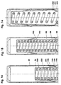
- the FIG. 1 shows a disposable or disposable injector with a permanently loaded spring energy storage.
- the disposable injector consists of a housing (200) surrounded by a triggering element (82) and a protective cap (120), a cylinder-piston unit (100) prefilled with, for example, an injection solution, a piston-actuating ram (60) and a helical compression spring (50) spring energy storage.
- the cylinder-piston unit (100) sits mostly in the protective cap (120).
- the housing (200) is a bent to a "U" sheet metal strip (201).
- the unwound, eg 18 millimeters wide, sheet metal strip (201) is about 240 millimeters long.
- the possibly made of spring steel sheet metal strip (201) has a wall thickness of eg 0.5 millimeters.
- the bent sheet-metal strip (201) consists of a central end plate (210) and two of them at least approximately vertically protruding bending-elastic legs (220).
- the at least partially aligned approximately parallel legs (220) are angled at their free ends in each case by 90 degrees inwardly to form there each a holding element (221).
- the holding elements (221) for example, 1.5 to 3 millimeters long, project towards each other. They form a plane that is aligned parallel to the end plate (210).
- each leg (220) has a recess into which the cylinder of the cylinder-piston unit (100) can be hooked by means of a respective pin.
- stiffening beads (211) protrude into the front plate (210) so far that they also center the last turn of the helical compression spring (50) on the front plate (210).
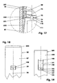
- each leg (220) is bent in a Z-shaped or S-shaped manner, wherein the double-angle bend is mirror-symmetrical to the center line (5), cf.
- FIG. 4 In this figure, the metal strip (201) is shown in the relaxed state.
- the middle area is a zone that follows FIG. 4 extends above and below the center of the housing (200) by approximately one quarter of the housing overall length.
- Each leg (220) consists of a front holding portion (233), a middle support portion (231) and a rear abutment portion (232).
- the holding section (233) is mostly straight running and runs after FIG. 4 parallel to the midline (5). It is followed by the relatively short support section (231).
- FIG. 17, includes, for example, an angle of 112 to 118 degrees with the holding section (233). Compared to the vertical, it is tilted by 65 degrees.
- the contact section (232) adjoins the support section (231). It extends to the face plate (210).
- the contact section (232) closes with the support section (231) - after FIG. 4 - an angle of 113 ⁇ 3 degrees. He lies after the FIGS. 1 and 6 over a large area on the trigger element (82).
- FIGS. 1 . 10 . 11 and 17 is located on the support portions (231) of the legs (220) of the piston-actuating rams (60).
- the latter is here a U-shaped bent metal strip, which consists of a central part, the stamp plate (73) and two guide legs (78).
- the stamping plate (73) is oriented parallel to the end plate (210).
- the guide legs (78) are at right angles from above. Between the guide legs (78) sits the helical compression spring (50). Possibly. are the guide legs (78) opposite the punch plate (73) equipped with stiffening beads, see.
- the stiffening beads (211) of the sheet metal part (201) FIG. 5 the stiffening beads (211) of the sheet metal part (201) FIG. 5 ,
- FIG. 17 has the stamp plate (73) in the area in which it rests against the respective support portion (231) of the leg (220), for example, a 25 ° bevel (75) to ensure a large-scale system.
- the piston actuating ram (60) has a width which is slightly smaller, ie approximately 0.1 to 0.3 millimeters, than the regular distance between the two legs (220). Accordingly, the piston-actuating ram (60) is guided laterally on the legs (220).
- FIG. 2 It can be seen that the guide legs (78) of the piston actuating punch (60) on the inner wall (89) of the trigger element (82) rest with play.
- the stamping plate (73) has, inter alia, the FIGS. 1 to 3 and 17 a central bore (76) for additionally guiding the piston (111) of the cylinder-piston unit (100) rearwardly.
- the two loaded on train legs (220) hold the piston actuating ram (60) on the stamp plate (73) in its biased position, see. FIG. 1 and 17 ,
- the legs (220) are supported with their support portions (231) on the lower 25 ° bevel (75) of the punch plate (73).
- the size of the respective contact surface between the individual support portion (231) and the corresponding 25 ° bevel (75) is in the range of 10 to 30 mm 2 .
- the made of sheet metal housing (200) is largely surrounded by a trigger element (82) in which it sits slidably.
- the triggering element (82) is here a square-edged tube which is closed at the rear with a cover (285) and forms part of a triggering unit (80).
- the made of plastic, such as a polyamide Pipe (82) has a front (21) and a rear portion (22).
- the front portion (21), which relates approximately to the front third of the trigger element (82), has the shape of a square tube with a square ring cross-section.
- the rear region (22) has a rectangular ring cross section, cf. FIG. 3 wherein the side wall (88) is about 5 percent wider than the side wall (87).
- a longitudinal groove (83) is partially arranged, which extends to the rear end of the trigger tube (82).
- the wall thickness of the side wall (87) is reduced to eg 0.5 millimeters.
- the longitudinal groove (83) terminates at the front in, for example, a recessed ramp (84), which is inclined relative to the inner wall (89) by approximately 75 degrees, cf. also FIG. 15 ,
- the inclination has the same orientation as the inclination of the support portions (231) of the legs (220) of the sheet metal strip (201).
- the longitudinal grooves (83) take in the case of a triggered injector in each case the contact portion (232) and the support portion (231) of the single leg (220) largely on, see.
- Figures 9 13 , and 16
- the locking tabs (181-183) protruding inwardly a few tenths of a millimeter are arranged, cf. also FIGS. 6 to 8 .
- the column (185) has a width of, for example, 0.5 millimeters. The width corresponds to the wall thickness of the front plate (210). At the places where two columns (185) abut each other at right angles, the locking tabs (181-183) are rounded.
- the first location (186) is the gap between the front (181) and middle latch tabs (182). In the horizontal gap there, the front plate (210) is locked, cf. FIG. 6 when the sheet metal strip (201) is mounted with the between the piston actuating punch (60) and the end plate (210) clamped helical compression spring (50) for further intermediate storage.
- the second location (187) is the gap between the middle (182) and rear latch tabs (183).
- the face plate (210) After the Figures 1 and 2 here sits the face plate (210) at a ready mounted, not triggered disposable injector. By locking the end plate (210) in this gap, a withdrawal of the housing (200) from the trigger tube (82) - after removing the protective cap (120) - prevented.
- the third digit (188) is the gap above the rear locking tab (183). In this position, the metal strip (201) remains after the triggering of the injector, see. FIG. 9 , There he is secured against unwanted disassembly of the then used or used injector.
- all locking elements (181-183) on the trigger element (82) are arranged. They fix partly temporarily, partially permanently the position of the end plate (210) relative to the trigger element (82). It is also conceivable to replace the latching elements (181-183) by at least one latching element arranged on the housing (200). The latter then engages eg in corresponding recesses of the triggering element (82) in order to realize comparable latching positions. In the FIGS. 10 to 16 . 18 and 19 such a variant is shown.
- each leg (220 for example, a 6 millimeter wide latching tongue (190) is arranged, see. FIG. 19 .
- the latching tongue (190) is created by working out a U-shaped, for example, 0.2 to 0.5 millimeters wide gap (197).
- the gap (197) ends in the respective rear region of the legs (220), ie in the vicinity of the end plate (210) in holes (198) to minimize the notch stresses there.
- the latching tongue (190) is bent several times, cf. also FIGS. 14 to 16 ,
- the latching tongue (190) consists of an outwardly resilient bending section (191) and a support section (192). The latter has a catch nub (193) approximately in the center.
- the latching tongue (190) serves as a transport lock. This corresponds to the first location (186) of the Rastgesperres (180) from the FIGS. 6 and 7 ,
- FIGS. 15 and 11 show the injector in the commercial state.
- the latching nubs (193) of the latching tongue (190) are latched into the latching bores (26) of the triggering element (82).
- the latching tongue (190) engages with its support section (192) in the window (25) of the triggering element (82).
- the bending section (191) rests against the rear edge of the window (25), while the support end face (194) rests against the front edge of the window (25). From this latching position, the sheet metal strip (201) can no longer be pulled out of the release tube (82) to the front.
- the locking recesses (25, 26) and the gaps (185, 197) are in the ready-mounted disposable injector, e.g. by a permanently glued or shrunk, e.g. Labeled possibly elastic film covered dust-tight.
- the lid (285) for example, glued to the trigger element (82), welded, latched or sprained. Possibly. the lid on the trigger element (82) is also formed.
- the lid (285) has two opposing cover tabs (286) each filling the cross-section of the longitudinal grooves (83) of the side walls (87) in the rear trigger tube area.
- the cover tabs (286) which are chamfered at their free ends to the interior (29), so far into the release tube (82) into that they after FIG. 1 the metal strip (201) in the region of the front plate (210) can be supported laterally with little play, provided that the injector is in the commercial state.
- the cylinder-piston unit (100) consists in the embodiment of a, with an injection solution (1) or a solvent, eg water for injection, filled, transparent cylinder (101), in the after FIG. 1 a piston (111) is seated in its rearward position.
- an injection solution (1) or a solvent, eg water for injection, filled, transparent cylinder (101) in the after FIG. 1 a piston (111) is seated in its rearward position.
- the cylinder (101) is eg a thick-walled pot.
- the cylinder bore is designed, for example, cylindrical or truncated cone-shaped.
- Its diameter is about 0.1 to 0.5 millimeters.
- This bore (106) is one to five times as long as its diameter. It ends in a cylindrical recess (107) of the bottom-side, outer end face (103) of the cylinder (101), cf. FIG. 9 , Possibly. can in the bottom of the cylinder (101) and two or more nozzle-like bores (106) may be arranged.
- An adhesive ring (108) adheres firmly to the end face (103) around the recess (107). The latter covers almost the entire end face (103).
- the spatial outer contour of the cylinder (101) is in the embodiment e.g. cuboid shaped. However, it can also be cylindrical.
- the cross section of the outer contour - it is oriented transversely to the center line (5) - is in the middle cylinder area a square area with a central bore. The cross-section is dimensioned so that the cylinder (101) with little play in the interior (29) of the trigger tube (82) slides.
- the cylinder (101) has in its outer contour in the upper, the release tube (82) facing quarter, for example, a circumferential retaining notch (104) with an example rectangular notched cross-section.
- a circumferential retaining notch (104) engage - for fixing the cylinder (101) in the injector - the hook-shaped holding elements (221) of the legs (220).
- the cylinder (101) tapers in the shape of a truncated pyramid. The angle enclosed by opposing pyramidal surfaces is for example 20 to 30 degrees. If necessary, the retaining notch (104) may also consist of only two mutually opposite individual notches.
- the cylinder (101) has a cylinder inner wall (109) which ends in the region of the rear cylinder end face in an annular groove (105) for receiving a sealing element (116).
- the cylinder (101) seated piston (111) has at its front, at least approximately conically shaped end face an axial annular groove (112) for receiving a sealing ring (114) or a permanently elastic sealant.
- the piston (111) has a waist in its central region and at its rear, e.g. a central, frusto-conical pin (118) which projects into the bore (76) of the stamping plate (73) with play.
- the piston (111) and the sealing element (116) close the filled cylinder interior (110) sterile.
- the cylindrical recess (107) of the bottom end face (103) of the cylinder (101) is after FIG. 11 For example, closed with a protective film (128).
- the protective film (128) adheres to the end face (103) via an adhesive ring (108). It has a pull tab on the side (129).
- an elastic plug In the middle region of the protective film (128) there is an elastic plug firmly adhering to the protective film (128) which sealingly fills the cavity of the recess (107).
- the one-piece protective cap (120) which consists geometrically in principle of five flat walls, enclosing the cylinder (101) laterally with little play. It has in the embodiment of the Figures 1-9 the same square tube cross section as the front portion (21) of the trigger tube (82).
- the upper, for example, planar end face of the protective cap (120) contacts the front end face of the square-shaped triggering element (82).
- the outer wall of the protective cap (120) has a profiling or structure to facilitate removal from the cylinder (101). In the exemplary embodiment, a groove profile (122) is used as profiling.
- the bottom of the protective cap (120) has a plug (121) which projects in a sealing manner into the recess (107) of the cylinder (101).
- the protective cap (120) adheres to the cylinder (101) via the adhesive ring (108).
- the latter has a considerably higher adhesive force relative to the cylinder (101) than relative to the bottom of the protective cap (120).
- the base is optionally provided with a profile or shoulder, so that the contact surface with respect to the adhesive ring (108) is smaller than the contact surface between the adhesive ring (108) and the cylinder-side end face (103).
- the helical compression spring (50) is transmitted via the stamp plate (73) on the legs (220). Due to the inclination of the chamfer (75) of the punching plate (73), the legs (220) are urged radially outward in the manner of a wedge gear, cf. FIG. 17 , The chamfers (75) contact the inclined support portions (231) of the legs (220). The contact portions (232) are at least almost flat against the inner wall of the trigger tube (82). The Trigger tube (82) thus supports the wedge gear-related transverse force permanently.
- the square-shaped release element (82) and the protective cap (120) touch at their end faces.
- this area is additionally surrounded by a banderole (90) as a security element.
- the tear-off or separable band (90) is, for example, a paper or film strip coated on one side with an adhesive.
- the film strip for example, once in a single layer surrounds the composite of triggering element (82) and protective cap (120). He glued the parts (82) and (120) temporarily.
- the band (90) is removed or separated so that the adhesive bond between the trigger element (82) and the protective cap (120) is released .
- the tear-off lug (96) lying in the region of the triggering element (82) is gripped and, thus, the band (90) is unwound, for example, in regions.
- the band (90) ruptures at a defined, eg rectilinear predetermined breaking point (93), which lies exactly in the region of the end faces.
- a defined, eg rectilinear predetermined breaking point (93) which lies exactly in the region of the end faces.
- FIGS. 6 and 7 show the injector at a mounting intermediate step.
- the helical compression spring (50) is plugged together with the piston actuating punch (60) and the sheet metal strip (201).
- the helical compression spring (50) in the finished formed sheet metal strip (201) is inserted so that a spring end on the end plate (210) comes to rest.
- the bow-shaped piston actuating punch (60) postponed is the bow-shaped piston actuating punch (60) postponed.
- the trigger tube (82) is pushed further over the metal strip (201) until the end plate (210) engages in the gap (185) located between the latching tabs (182) and (183).
- the holding elements (221) firmly engage in the retaining notch (104) and thus fix the cylinder-piston unit (100) in the trigger tube (82).
- the in FIG. 1 installation step is missing only the attachment of the tamper-evident closure (90) and pasting the longitudinal grooves (83) and the gaps (185) by means of a labeled foil.
- FIGS. 10 to 16 . 18 and 19 show one opposite the FIGS. 1 to 9 partly different variant. It differs among other things in seven points.
- the metal strip (201) for lateral centering between the side walls (87) of the trigger tube (82) per leg (220) at least one latching tongue (190).
- the piston actuating punch (60) is only a square plate without a bore, which has two or four chamfers (75) on its lower end face (74). Possibly. is at the upper end face of the square plate, a guide pin (62) - here shown in dashed lines - attached or molded.
- the piston (111) has no guide pin at its rear end.
- the trigger element (82) instead of the latching tabs (181-183), see.
- the trigger member (82) has a lid (285) without the lid tabs (286) after FIG. 1 ,
- the cylinder (101) instead of the protective cap (120), see. FIG. 1 , only a protective film (128), cf. FIGS. 10 and 11 ,
- the band (90) is wrapped only around the cylinder (101).
- the foil of the band (90) has such a large wall thickness that it reliably blocks a displacement of the triggering element (82) in the release direction (6).
- FIGS. 20 and 21 show an injector whose sheet metal strip (201) with a Rasteinsülpung (234) and a guide protuberance (235) is equipped.
- This sheet metal strip (201) belongs to a release tube (82), which has a rear (83) and a front longitudinal groove (23) per side wall (87).
- the longitudinal grooves (83, 23) are through a several millimeters wide Bridge (81), which is arranged approximately centrally in the trigger tube, separated from each other.
- the Rasteinstülpung (234) of the metal strip (201), the rear portion of which is the support portion (231) is shaped so that it surrounds the web (81) with a triggered injector with clearance, see. FIG. 21 ,
- the wave-shaped guide protuberance (235) is located in the vicinity of the holding elements (221). It has the task of supporting the front ends of the legs (220) with their holding elements (221) so that the holding elements (221) securely engage in the holding notches (104) of the cylinder (101) in each operating state of the injector.
- the single injector is first unlocked by the detachment of the tear-off tab (96). Subsequently, the protective cap (120) or the protective film (128) is removed from the cylinder-piston unit (100). Now position the injector with the adhesive ring (108) in front of the disinfected injection site.
- the disposable injector on the trigger tube (82) is held in the fist. For example, the thumb of the holding hand rests on the lid (285), e.g. like holding a pen.
- the trigger tube (82) is moved in the direction of the cylinder-piston unit (100).
- the trigger element (82) slides on the metal strip (201) linearly downwards, ie in the direction of the injection site.
- the abutment portions (232) of the legs (220) slip over the edge (85) and snap under the force of the spring element (50) in the transverse direction outwardly into the longitudinal grooves (83).
- the support sections (231) release the piston actuating punch (60). This rockets unhindered down.
- the end face (74) of the stamping plate (73) strikes the end face of the piston (111), which was previously located a few tenths of a millimeter or a few millimeters away.
- the piston (111) pushes the injection solution or the medicament (1), for example initially with 300 x 10 5 Pa through the nozzle (106) until the cylinder (101) is emptied, see. FIG. 9. With the delivery of the injection solution (1), the injection process is ended.
- the exemplary embodiments show injectors whose housing-side limbs (220) are aligned in pairs at least approximately parallel to one another - an angular deviation of ⁇ 2 angular degrees is permissible.
- the legs (220) lie in parallel planes, wherein the planes-seen in the injector cross-section-form the opposite sides of a rectangle.
- the plane of the injector cross section is normal - that is perpendicular - to the center line (5).
- These sides may also belong to a rhombus, a parallelogram, a trapezoid or an oblique square.
- the legs (220) in each case in pairs the same length and the support sections (231) are located opposite to the same height, see. FIGS. 1, 4 . 9 etc. This is not absolutely necessary.
- the support sections (231) can be at different heights if, accordingly, the contact surfaces of the piston actuating punch (60) and the return surfaces (84) are positioned offset.
Landscapes
- Health & Medical Sciences (AREA)
- Vascular Medicine (AREA)
- Engineering & Computer Science (AREA)
- Anesthesiology (AREA)
- Biomedical Technology (AREA)
- Heart & Thoracic Surgery (AREA)
- Hematology (AREA)
- Life Sciences & Earth Sciences (AREA)
- Animal Behavior & Ethology (AREA)
- General Health & Medical Sciences (AREA)
- Public Health (AREA)
- Veterinary Medicine (AREA)
- Infusion, Injection, And Reservoir Apparatuses (AREA)
- Portable Nailing Machines And Staplers (AREA)
Applications Claiming Priority (2)
| Application Number | Priority Date | Filing Date | Title |
|---|---|---|---|
| DE102008063517A DE102008063517A1 (de) | 2008-12-18 | 2008-12-18 | Einmalinjektor mit einem biegeelastischen Gehäuse II |
| PCT/EP2009/008613 WO2010069469A1 (de) | 2008-12-18 | 2009-12-03 | Einmalinjektor mit einem biegeelastischen gehäuse |
Publications (2)
| Publication Number | Publication Date |
|---|---|
| EP2367583A1 EP2367583A1 (de) | 2011-09-28 |
| EP2367583B1 true EP2367583B1 (de) | 2016-04-13 |
Family
ID=42028092
Family Applications (1)
| Application Number | Title | Priority Date | Filing Date |
|---|---|---|---|
| EP09765036.0A Not-in-force EP2367583B1 (de) | 2008-12-18 | 2009-12-03 | Nadelloser einmalinjektor mit einem biegeelastischen gehäuse |
Country Status (17)
| Country | Link |
|---|---|
| US (1) | US8105271B2 (pt) |
| EP (1) | EP2367583B1 (pt) |
| JP (1) | JP5748667B2 (pt) |
| KR (1) | KR101630894B1 (pt) |
| CN (1) | CN102245232B (pt) |
| AR (1) | AR074693A1 (pt) |
| AU (1) | AU2009328679B2 (pt) |
| BR (1) | BRPI0923071B8 (pt) |
| CA (1) | CA2746869C (pt) |
| DE (1) | DE102008063517A1 (pt) |
| ES (1) | ES2582230T3 (pt) |
| IL (1) | IL213554A0 (pt) |
| MX (1) | MX2011006557A (pt) |
| RU (1) | RU2530771C2 (pt) |
| TW (1) | TW201032853A (pt) |
| WO (1) | WO2010069469A1 (pt) |
| ZA (1) | ZA201103229B (pt) |
Families Citing this family (16)
| Publication number | Priority date | Publication date | Assignee | Title |
|---|---|---|---|---|
| US8052645B2 (en) | 2008-07-23 | 2011-11-08 | Avant Medical Corp. | System and method for an injection using a syringe needle |
| US8177749B2 (en) | 2008-05-20 | 2012-05-15 | Avant Medical Corp. | Cassette for a hidden injection needle |
| US9974904B2 (en) | 2008-05-20 | 2018-05-22 | Avant Medical Corp. | Autoinjector system |
| DE102010018529A1 (de) | 2010-04-27 | 2011-10-27 | Lts Lohmann Therapie-Systeme Ag | Einmalinjektor mit biegeelastischem Kolbenbetätigungsstempel |
| CA3021845C (en) | 2011-04-20 | 2022-03-29 | Amgen Inc. | Autoinjector apparatus |
| USD898908S1 (en) | 2012-04-20 | 2020-10-13 | Amgen Inc. | Pharmaceutical product cassette for an injection device |
| GB201212238D0 (en) * | 2012-07-10 | 2012-08-22 | Oval Medical Technologies Ltd | Drug delivery device with stressed plunger rod |
| TWI580451B (zh) | 2013-03-15 | 2017-05-01 | 安美基公司 | 用於注射器之匣盒及使用具有自動注射器及匣盒之自動注射器設備之方法 |
| CA2904661C (en) | 2013-03-15 | 2022-03-15 | Amgen Inc. | Drug cassette, autoinjector, and autoinjector system |
| MX2016011173A (es) | 2014-02-26 | 2016-12-16 | Allergan Inc | Aparato de suministro de implantes intraoculares y metodos para su uso. |
| CN106659854B (zh) * | 2014-06-04 | 2020-07-10 | 大成化工株式会社 | 注射器盖、带针注射器、及预充式注射器制剂 |
| JP6617158B2 (ja) * | 2015-05-04 | 2019-12-11 | エルテーエス ローマン テラピー−ジステーメ アーゲー | トリガの信頼性を高めた使い捨ての注射器 |
| CN109310338B (zh) * | 2016-06-29 | 2021-11-19 | 皮科洛医疗公司 | 用于血管导航、评估和/或诊断的装置和方法 |
| GB201819059D0 (en) * | 2018-11-22 | 2019-01-09 | Enesi Pharma Ltd | Single-use cassette assembly |
| KR102221358B1 (ko) | 2018-12-26 | 2021-03-02 | 주식회사피앤씨 | 성능이 향상된 스팀 인젝터 및 이를 이용한 수 처리 시스템 |
| CN110975124B (zh) * | 2019-12-26 | 2021-08-24 | 修红梅 | 一种耳鼻喉护理用便携式喷药器 |
Family Cites Families (22)
| Publication number | Priority date | Publication date | Assignee | Title |
|---|---|---|---|---|
| DE84901C (pt) | 1900-01-01 | |||
| DE831756C (de) | 1950-07-19 | 1952-02-18 | Dr Med Paul Schneller | Behaelter fuer Injektionsspritzen |
| GB805184A (en) * | 1957-01-29 | 1958-12-03 | Becton Dickinson Co | Hypodermic assembly |
| FR1172205A (fr) | 1957-02-05 | 1959-02-06 | Becton Dickinson Co | Seringue à injections sous-cutanées |
| NL265346A (pt) | 1960-06-10 | |||
| US3557784A (en) * | 1968-12-24 | 1971-01-26 | Walter A Shields | Syringe |
| EP0518416A1 (en) * | 1991-06-13 | 1992-12-16 | Duphar International Research B.V | Injection device |
| JPH08505543A (ja) | 1992-11-19 | 1996-06-18 | テブロ ソシエテ アノニム | 予充填注射器用の使い捨て自動注射装置 |
| JP3487856B2 (ja) * | 1993-07-31 | 2004-01-19 | ウェストン メディカル リミテッド | 無針注射器 |
| WO1996024398A1 (en) | 1995-02-06 | 1996-08-15 | Weston Medical Limited | Needle-less injector |
| GB9504878D0 (en) * | 1995-03-10 | 1995-04-26 | Weston Medical Ltd | Viscously coupled actuator |
| GB9607549D0 (en) * | 1996-04-11 | 1996-06-12 | Weston Medical Ltd | Spring-powered dispensing device |
| JP2003529392A (ja) | 1999-04-16 | 2003-10-07 | パウダージェクト リサーチ リミテッド | 無針注射器 |
| US6793646B1 (en) * | 1999-04-16 | 2004-09-21 | Becton Dickinson And Company | Pen style injector with automated substance combining feature |
| US6558348B2 (en) | 2000-04-07 | 2003-05-06 | Equidyne Systems, Inc. | Low cost disposable needleless injector system for variable and fixed dose applications |
| WO2003070296A2 (en) | 2002-02-15 | 2003-08-28 | Antares Pharma, Inc. | Injector with bypass channel |
| DE10351594A1 (de) * | 2003-11-05 | 2005-06-16 | Tecpharma Licensing Ag | Vorrichtung für die Verabreichung eines injizierbaren Produkts |
| DE602005003009T2 (de) | 2004-01-23 | 2008-08-14 | The Medical House Plc, Attercliffe | Injektionsvorrichtung |
| DE102005007614A1 (de) * | 2005-02-18 | 2006-08-24 | Tecpharma Licensing Ag | Autoinjektor mit einer Auslöseverriegelung |
| DE102007008369A1 (de) * | 2007-02-16 | 2008-08-21 | Lts Lohmann Therapie-Systeme Ag | Einweginjektor mit mindestens einem zentralen Zugstab |
| DE102007031630B3 (de) | 2007-07-06 | 2008-12-24 | Lts Lohmann Therapie-Systeme Ag | Einweginjektor mit mindestens einem Stützstab |
| DE102007034871A1 (de) | 2007-07-24 | 2009-01-29 | Lts Lohmann Therapie-Systeme Ag | Einweginjektor mit handbetätigbarem Kolben |
-
2008
- 2008-12-18 DE DE102008063517A patent/DE102008063517A1/de not_active Withdrawn
-
2009
- 2009-12-03 WO PCT/EP2009/008613 patent/WO2010069469A1/de active Application Filing
- 2009-12-03 CN CN2009801502356A patent/CN102245232B/zh not_active Expired - Fee Related
- 2009-12-03 KR KR1020117014085A patent/KR101630894B1/ko active IP Right Grant
- 2009-12-03 AU AU2009328679A patent/AU2009328679B2/en not_active Ceased
- 2009-12-03 JP JP2011541145A patent/JP5748667B2/ja not_active Expired - Fee Related
- 2009-12-03 ES ES09765036.0T patent/ES2582230T3/es active Active
- 2009-12-03 BR BRPI0923071A patent/BRPI0923071B8/pt not_active IP Right Cessation
- 2009-12-03 EP EP09765036.0A patent/EP2367583B1/de not_active Not-in-force
- 2009-12-03 CA CA2746869A patent/CA2746869C/en not_active Expired - Fee Related
- 2009-12-03 RU RU2011124310/14A patent/RU2530771C2/ru not_active IP Right Cessation
- 2009-12-03 MX MX2011006557A patent/MX2011006557A/es active IP Right Grant
- 2009-12-16 TW TW098143145A patent/TW201032853A/zh unknown
- 2009-12-16 AR ARP090104916A patent/AR074693A1/es unknown
-
2011
- 2011-05-03 ZA ZA2011/03229A patent/ZA201103229B/en unknown
- 2011-06-14 IL IL213554A patent/IL213554A0/en unknown
- 2011-06-15 US US13/134,721 patent/US8105271B2/en not_active Expired - Fee Related
Also Published As
| Publication number | Publication date |
|---|---|
| BRPI0923071A2 (pt) | 2010-06-24 |
| WO2010069469A1 (de) | 2010-06-24 |
| CA2746869C (en) | 2017-11-07 |
| JP5748667B2 (ja) | 2015-07-15 |
| IL213554A0 (en) | 2011-07-31 |
| AU2009328679A1 (en) | 2011-07-07 |
| EP2367583A1 (de) | 2011-09-28 |
| CA2746869A1 (en) | 2010-06-24 |
| AR074693A1 (es) | 2011-02-02 |
| BRPI0923071B8 (pt) | 2021-06-22 |
| JP2012511977A (ja) | 2012-05-31 |
| US8105271B2 (en) | 2012-01-31 |
| TW201032853A (en) | 2010-09-16 |
| ES2582230T3 (es) | 2016-09-09 |
| KR20110102348A (ko) | 2011-09-16 |
| RU2530771C2 (ru) | 2014-10-10 |
| MX2011006557A (es) | 2011-07-20 |
| CN102245232A (zh) | 2011-11-16 |
| RU2011124310A (ru) | 2012-12-27 |
| ZA201103229B (en) | 2012-04-25 |
| CN102245232B (zh) | 2013-11-06 |
| KR101630894B1 (ko) | 2016-06-15 |
| BRPI0923071B1 (pt) | 2020-04-22 |
| DE102008063517A1 (de) | 2010-07-01 |
| US20110251549A1 (en) | 2011-10-13 |
| AU2009328679B2 (en) | 2014-05-29 |
Similar Documents
| Publication | Publication Date | Title |
|---|---|---|
| EP2367583B1 (de) | Nadelloser einmalinjektor mit einem biegeelastischen gehäuse | |
| EP2121082B1 (de) | Einweginjektor mit mindestens einem zughaken | |
| EP3490647B1 (de) | Injektionsvorrichtung mit äusserer kappe mit nadelschutzkappenentfernerelement und verfahren zum montieren einer injektionsvorrichtung | |
| EP2164546B1 (de) | Einweginjektor mit mindestens einem stützstab | |
| EP2229202B1 (de) | Einweginjektor mit zweikolbigem zweikammersystem | |
| EP1962929B1 (de) | Einweginjektor mit dauergeladenem federenergiespeicher | |
| EP2224978B1 (de) | Einweginjektor mit handbetätigbarem kolben und einem zweikammersystem | |
| EP1684830A1 (de) | Vorrichtung für die verabreichung eines injizierbaren produkts | |
| DE102007008369A1 (de) | Einweginjektor mit mindestens einem zentralen Zugstab | |
| EP2162172A1 (de) | Einweginjektor mit mindestens einem druckstab und einer verschlusskappe | |
| DE102007034871A1 (de) | Einweginjektor mit handbetätigbarem Kolben | |
| DE10036594A1 (de) | Austragvorrichtung für Medien | |
| EP2367582B1 (de) | Einmalinjektor mit einem biegeelastischen metallgehäuse | |
| WO2021197804A1 (de) | Autoinjektor mit einem mehrkammerproduktbehälter | |
| EP2361106A1 (de) | Injektor mit zylinder-kolben-einheit und dauerhaft sterilem aktiven kolbenhemd | |
| WO2022184388A1 (de) | Autoinjektor mit einer nadelschutzhülse | |
| WO2010034381A1 (de) | Injektor und zwei-kammer-system mit sterilen komponenten | |
| EP2563428B1 (de) | Einmalinjektor mit biegeelastischem kolbenbetätigungsstempel | |
| DE102008063518A1 (de) | Pumpfähiger Einmalinjektor mit einem biegeelastischen Gehäuse |
Legal Events
| Date | Code | Title | Description |
|---|---|---|---|
| PUAI | Public reference made under article 153(3) epc to a published international application that has entered the european phase |
Free format text: ORIGINAL CODE: 0009012 |
|
| 17P | Request for examination filed |
Effective date: 20110525 |
|
| AK | Designated contracting states |
Kind code of ref document: A1 Designated state(s): AT BE BG CH CY CZ DE DK EE ES FI FR GB GR HR HU IE IS IT LI LT LU LV MC MK MT NL NO PL PT RO SE SI SK SM TR |
|
| DAX | Request for extension of the european patent (deleted) | ||
| GRAP | Despatch of communication of intention to grant a patent |
Free format text: ORIGINAL CODE: EPIDOSNIGR1 |
|
| INTG | Intention to grant announced |
Effective date: 20151111 |
|
| GRAS | Grant fee paid |
Free format text: ORIGINAL CODE: EPIDOSNIGR3 |
|
| GRAA | (expected) grant |
Free format text: ORIGINAL CODE: 0009210 |
|
| AK | Designated contracting states |
Kind code of ref document: B1 Designated state(s): AT BE BG CH CY CZ DE DK EE ES FI FR GB GR HR HU IE IS IT LI LT LU LV MC MK MT NL NO PL PT RO SE SI SK SM TR |
|
| REG | Reference to a national code |
Ref country code: GB Ref legal event code: FG4D Free format text: NOT ENGLISH |
|
| REG | Reference to a national code |
Ref country code: AT Ref legal event code: REF Ref document number: 789427 Country of ref document: AT Kind code of ref document: T Effective date: 20160415 Ref country code: CH Ref legal event code: EP |
|
| REG | Reference to a national code |
Ref country code: IE Ref legal event code: FG4D Free format text: LANGUAGE OF EP DOCUMENT: GERMAN |
|
| REG | Reference to a national code |
Ref country code: DE Ref legal event code: R096 Ref document number: 502009012432 Country of ref document: DE |
|
| REG | Reference to a national code |
Ref country code: LT Ref legal event code: MG4D |
|
| REG | Reference to a national code |
Ref country code: ES Ref legal event code: FG2A Ref document number: 2582230 Country of ref document: ES Kind code of ref document: T3 Effective date: 20160909 |
|
| REG | Reference to a national code |
Ref country code: NL Ref legal event code: MP Effective date: 20160413 |
|
| PG25 | Lapsed in a contracting state [announced via postgrant information from national office to epo] |
Ref country code: PL Free format text: LAPSE BECAUSE OF FAILURE TO SUBMIT A TRANSLATION OF THE DESCRIPTION OR TO PAY THE FEE WITHIN THE PRESCRIBED TIME-LIMIT Effective date: 20160413 Ref country code: LT Free format text: LAPSE BECAUSE OF FAILURE TO SUBMIT A TRANSLATION OF THE DESCRIPTION OR TO PAY THE FEE WITHIN THE PRESCRIBED TIME-LIMIT Effective date: 20160413 Ref country code: NO Free format text: LAPSE BECAUSE OF FAILURE TO SUBMIT A TRANSLATION OF THE DESCRIPTION OR TO PAY THE FEE WITHIN THE PRESCRIBED TIME-LIMIT Effective date: 20160713 Ref country code: NL Free format text: LAPSE BECAUSE OF FAILURE TO SUBMIT A TRANSLATION OF THE DESCRIPTION OR TO PAY THE FEE WITHIN THE PRESCRIBED TIME-LIMIT Effective date: 20160413 Ref country code: FI Free format text: LAPSE BECAUSE OF FAILURE TO SUBMIT A TRANSLATION OF THE DESCRIPTION OR TO PAY THE FEE WITHIN THE PRESCRIBED TIME-LIMIT Effective date: 20160413 |
|
| PG25 | Lapsed in a contracting state [announced via postgrant information from national office to epo] |
Ref country code: LV Free format text: LAPSE BECAUSE OF FAILURE TO SUBMIT A TRANSLATION OF THE DESCRIPTION OR TO PAY THE FEE WITHIN THE PRESCRIBED TIME-LIMIT Effective date: 20160413 Ref country code: SE Free format text: LAPSE BECAUSE OF FAILURE TO SUBMIT A TRANSLATION OF THE DESCRIPTION OR TO PAY THE FEE WITHIN THE PRESCRIBED TIME-LIMIT Effective date: 20160413 Ref country code: PT Free format text: LAPSE BECAUSE OF FAILURE TO SUBMIT A TRANSLATION OF THE DESCRIPTION OR TO PAY THE FEE WITHIN THE PRESCRIBED TIME-LIMIT Effective date: 20160816 Ref country code: GR Free format text: LAPSE BECAUSE OF FAILURE TO SUBMIT A TRANSLATION OF THE DESCRIPTION OR TO PAY THE FEE WITHIN THE PRESCRIBED TIME-LIMIT Effective date: 20160714 Ref country code: HR Free format text: LAPSE BECAUSE OF FAILURE TO SUBMIT A TRANSLATION OF THE DESCRIPTION OR TO PAY THE FEE WITHIN THE PRESCRIBED TIME-LIMIT Effective date: 20160413 |
|
| REG | Reference to a national code |
Ref country code: FR Ref legal event code: PLFP Year of fee payment: 8 |
|
| REG | Reference to a national code |
Ref country code: DE Ref legal event code: R097 Ref document number: 502009012432 Country of ref document: DE |
|
| PG25 | Lapsed in a contracting state [announced via postgrant information from national office to epo] |
Ref country code: DK Free format text: LAPSE BECAUSE OF FAILURE TO SUBMIT A TRANSLATION OF THE DESCRIPTION OR TO PAY THE FEE WITHIN THE PRESCRIBED TIME-LIMIT Effective date: 20160413 Ref country code: RO Free format text: LAPSE BECAUSE OF FAILURE TO SUBMIT A TRANSLATION OF THE DESCRIPTION OR TO PAY THE FEE WITHIN THE PRESCRIBED TIME-LIMIT Effective date: 20160413 Ref country code: SK Free format text: LAPSE BECAUSE OF FAILURE TO SUBMIT A TRANSLATION OF THE DESCRIPTION OR TO PAY THE FEE WITHIN THE PRESCRIBED TIME-LIMIT Effective date: 20160413 Ref country code: EE Free format text: LAPSE BECAUSE OF FAILURE TO SUBMIT A TRANSLATION OF THE DESCRIPTION OR TO PAY THE FEE WITHIN THE PRESCRIBED TIME-LIMIT Effective date: 20160413 Ref country code: CZ Free format text: LAPSE BECAUSE OF FAILURE TO SUBMIT A TRANSLATION OF THE DESCRIPTION OR TO PAY THE FEE WITHIN THE PRESCRIBED TIME-LIMIT Effective date: 20160413 |
|
| PLBE | No opposition filed within time limit |
Free format text: ORIGINAL CODE: 0009261 |
|
| STAA | Information on the status of an ep patent application or granted ep patent |
Free format text: STATUS: NO OPPOSITION FILED WITHIN TIME LIMIT |
|
| PG25 | Lapsed in a contracting state [announced via postgrant information from national office to epo] |
Ref country code: SM Free format text: LAPSE BECAUSE OF FAILURE TO SUBMIT A TRANSLATION OF THE DESCRIPTION OR TO PAY THE FEE WITHIN THE PRESCRIBED TIME-LIMIT Effective date: 20160413 |
|
| 26N | No opposition filed |
Effective date: 20170116 |
|
| PG25 | Lapsed in a contracting state [announced via postgrant information from national office to epo] |
Ref country code: BE Free format text: LAPSE BECAUSE OF NON-PAYMENT OF DUE FEES Effective date: 20161231 Ref country code: SI Free format text: LAPSE BECAUSE OF FAILURE TO SUBMIT A TRANSLATION OF THE DESCRIPTION OR TO PAY THE FEE WITHIN THE PRESCRIBED TIME-LIMIT Effective date: 20160413 |
|
| REG | Reference to a national code |
Ref country code: CH Ref legal event code: PL |
|
| PG25 | Lapsed in a contracting state [announced via postgrant information from national office to epo] |
Ref country code: MC Free format text: LAPSE BECAUSE OF FAILURE TO SUBMIT A TRANSLATION OF THE DESCRIPTION OR TO PAY THE FEE WITHIN THE PRESCRIBED TIME-LIMIT Effective date: 20160413 |
|
| REG | Reference to a national code |
Ref country code: IE Ref legal event code: MM4A |
|
| PG25 | Lapsed in a contracting state [announced via postgrant information from national office to epo] |
Ref country code: LI Free format text: LAPSE BECAUSE OF NON-PAYMENT OF DUE FEES Effective date: 20161231 Ref country code: LU Free format text: LAPSE BECAUSE OF NON-PAYMENT OF DUE FEES Effective date: 20161203 Ref country code: CH Free format text: LAPSE BECAUSE OF NON-PAYMENT OF DUE FEES Effective date: 20161231 |
|
| PG25 | Lapsed in a contracting state [announced via postgrant information from national office to epo] |
Ref country code: IE Free format text: LAPSE BECAUSE OF NON-PAYMENT OF DUE FEES Effective date: 20161203 |
|
| REG | Reference to a national code |
Ref country code: FR Ref legal event code: PLFP Year of fee payment: 9 |
|
| REG | Reference to a national code |
Ref country code: BE Ref legal event code: MM Effective date: 20161231 |
|
| REG | Reference to a national code |
Ref country code: AT Ref legal event code: MM01 Ref document number: 789427 Country of ref document: AT Kind code of ref document: T Effective date: 20161203 |
|
| PG25 | Lapsed in a contracting state [announced via postgrant information from national office to epo] |
Ref country code: HU Free format text: LAPSE BECAUSE OF FAILURE TO SUBMIT A TRANSLATION OF THE DESCRIPTION OR TO PAY THE FEE WITHIN THE PRESCRIBED TIME-LIMIT; INVALID AB INITIO Effective date: 20091203 Ref country code: AT Free format text: LAPSE BECAUSE OF NON-PAYMENT OF DUE FEES Effective date: 20161203 Ref country code: CY Free format text: LAPSE BECAUSE OF FAILURE TO SUBMIT A TRANSLATION OF THE DESCRIPTION OR TO PAY THE FEE WITHIN THE PRESCRIBED TIME-LIMIT Effective date: 20160413 |
|
| PG25 | Lapsed in a contracting state [announced via postgrant information from national office to epo] |
Ref country code: TR Free format text: LAPSE BECAUSE OF FAILURE TO SUBMIT A TRANSLATION OF THE DESCRIPTION OR TO PAY THE FEE WITHIN THE PRESCRIBED TIME-LIMIT Effective date: 20160413 Ref country code: MK Free format text: LAPSE BECAUSE OF FAILURE TO SUBMIT A TRANSLATION OF THE DESCRIPTION OR TO PAY THE FEE WITHIN THE PRESCRIBED TIME-LIMIT Effective date: 20160413 Ref country code: IS Free format text: LAPSE BECAUSE OF FAILURE TO SUBMIT A TRANSLATION OF THE DESCRIPTION OR TO PAY THE FEE WITHIN THE PRESCRIBED TIME-LIMIT Effective date: 20160413 |
|
| PG25 | Lapsed in a contracting state [announced via postgrant information from national office to epo] |
Ref country code: BG Free format text: LAPSE BECAUSE OF FAILURE TO SUBMIT A TRANSLATION OF THE DESCRIPTION OR TO PAY THE FEE WITHIN THE PRESCRIBED TIME-LIMIT Effective date: 20160413 |
|
| PG25 | Lapsed in a contracting state [announced via postgrant information from national office to epo] |
Ref country code: MT Free format text: LAPSE BECAUSE OF FAILURE TO SUBMIT A TRANSLATION OF THE DESCRIPTION OR TO PAY THE FEE WITHIN THE PRESCRIBED TIME-LIMIT Effective date: 20160413 |
|
| PGFP | Annual fee paid to national office [announced via postgrant information from national office to epo] |
Ref country code: DE Payment date: 20191210 Year of fee payment: 11 |
|
| PGFP | Annual fee paid to national office [announced via postgrant information from national office to epo] |
Ref country code: IT Payment date: 20191230 Year of fee payment: 11 Ref country code: FR Payment date: 20191220 Year of fee payment: 11 |
|
| PGFP | Annual fee paid to national office [announced via postgrant information from national office to epo] |
Ref country code: GB Payment date: 20191220 Year of fee payment: 11 Ref country code: ES Payment date: 20200121 Year of fee payment: 11 |
|
| REG | Reference to a national code |
Ref country code: DE Ref legal event code: R119 Ref document number: 502009012432 Country of ref document: DE |
|
| GBPC | Gb: european patent ceased through non-payment of renewal fee |
Effective date: 20201203 |
|
| PG25 | Lapsed in a contracting state [announced via postgrant information from national office to epo] |
Ref country code: FR Free format text: LAPSE BECAUSE OF NON-PAYMENT OF DUE FEES Effective date: 20201231 Ref country code: IT Free format text: LAPSE BECAUSE OF NON-PAYMENT OF DUE FEES Effective date: 20201203 |
|
| PG25 | Lapsed in a contracting state [announced via postgrant information from national office to epo] |
Ref country code: DE Free format text: LAPSE BECAUSE OF NON-PAYMENT OF DUE FEES Effective date: 20210701 Ref country code: GB Free format text: LAPSE BECAUSE OF NON-PAYMENT OF DUE FEES Effective date: 20201203 |
|
| REG | Reference to a national code |
Ref country code: ES Ref legal event code: FD2A Effective date: 20220207 |
|
| PG25 | Lapsed in a contracting state [announced via postgrant information from national office to epo] |
Ref country code: ES Free format text: LAPSE BECAUSE OF NON-PAYMENT OF DUE FEES Effective date: 20201204 |