EP2365176B1 - Dispositif de déverrouillage d'une fenêtre, d'un battant ou analogue - Google Patents
Dispositif de déverrouillage d'une fenêtre, d'un battant ou analogue Download PDFInfo
- Publication number
- EP2365176B1 EP2365176B1 EP11157133.7A EP11157133A EP2365176B1 EP 2365176 B1 EP2365176 B1 EP 2365176B1 EP 11157133 A EP11157133 A EP 11157133A EP 2365176 B1 EP2365176 B1 EP 2365176B1
- Authority
- EP
- European Patent Office
- Prior art keywords
- window
- bracket
- drive unit
- console
- frame
- Prior art date
- Legal status (The legal status is an assumption and is not a legal conclusion. Google has not performed a legal analysis and makes no representation as to the accuracy of the status listed.)
- Active
Links
- 238000006073 displacement reaction Methods 0.000 claims description 5
- 230000008878 coupling Effects 0.000 claims description 3
- 238000010168 coupling process Methods 0.000 claims description 3
- 238000005859 coupling reaction Methods 0.000 claims description 3
- 230000001066 destructive effect Effects 0.000 description 2
- 239000000463 material Substances 0.000 description 2
- 239000002184 metal Substances 0.000 description 2
- 230000005540 biological transmission Effects 0.000 description 1
- 238000004891 communication Methods 0.000 description 1
- 238000013461 design Methods 0.000 description 1
- 238000003780 insertion Methods 0.000 description 1
- 230000037431 insertion Effects 0.000 description 1
- 238000009413 insulation Methods 0.000 description 1
- 230000007257 malfunction Effects 0.000 description 1
- 238000000034 method Methods 0.000 description 1
- 238000012545 processing Methods 0.000 description 1
Images


Classifications
-
- E—FIXED CONSTRUCTIONS
- E05—LOCKS; KEYS; WINDOW OR DOOR FITTINGS; SAFES
- E05F—DEVICES FOR MOVING WINGS INTO OPEN OR CLOSED POSITION; CHECKS FOR WINGS; WING FITTINGS NOT OTHERWISE PROVIDED FOR, CONCERNED WITH THE FUNCTIONING OF THE WING
- E05F15/00—Power-operated mechanisms for wings
- E05F15/60—Power-operated mechanisms for wings using electrical actuators
- E05F15/603—Power-operated mechanisms for wings using electrical actuators using rotary electromotors
- E05F15/611—Power-operated mechanisms for wings using electrical actuators using rotary electromotors for swinging wings
- E05F15/616—Power-operated mechanisms for wings using electrical actuators using rotary electromotors for swinging wings operated by push-pull mechanisms
- E05F15/619—Power-operated mechanisms for wings using electrical actuators using rotary electromotors for swinging wings operated by push-pull mechanisms using flexible or rigid rack-and-pinion arrangements
-
- E—FIXED CONSTRUCTIONS
- E05—LOCKS; KEYS; WINDOW OR DOOR FITTINGS; SAFES
- E05Y—INDEXING SCHEME RELATING TO HINGES OR OTHER SUSPENSION DEVICES FOR DOORS, WINDOWS OR WINGS AND DEVICES FOR MOVING WINGS INTO OPEN OR CLOSED POSITION, CHECKS FOR WINGS AND WING FITTINGS NOT OTHERWISE PROVIDED FOR, CONCERNED WITH THE FUNCTIONING OF THE WING
- E05Y2201/00—Constructional elements; Accessories therefore
- E05Y2201/20—Brakes; Disengaging means, e.g. clutches; Holders, e.g. locks; Stops; Accessories therefore
- E05Y2201/23—Actuation thereof
- E05Y2201/244—Actuation thereof by manual operation
-
- E—FIXED CONSTRUCTIONS
- E05—LOCKS; KEYS; WINDOW OR DOOR FITTINGS; SAFES
- E05Y—INDEXING SCHEME RELATING TO HINGES OR OTHER SUSPENSION DEVICES FOR DOORS, WINDOWS OR WINGS AND DEVICES FOR MOVING WINGS INTO OPEN OR CLOSED POSITION, CHECKS FOR WINGS AND WING FITTINGS NOT OTHERWISE PROVIDED FOR, CONCERNED WITH THE FUNCTIONING OF THE WING
- E05Y2201/00—Constructional elements; Accessories therefore
- E05Y2201/40—Motors; Magnets; Springs; Weights; Accessories therefore
- E05Y2201/43—Motors
- E05Y2201/434—Electromotors; Details thereof
-
- E—FIXED CONSTRUCTIONS
- E05—LOCKS; KEYS; WINDOW OR DOOR FITTINGS; SAFES
- E05Y—INDEXING SCHEME RELATING TO HINGES OR OTHER SUSPENSION DEVICES FOR DOORS, WINDOWS OR WINGS AND DEVICES FOR MOVING WINGS INTO OPEN OR CLOSED POSITION, CHECKS FOR WINGS AND WING FITTINGS NOT OTHERWISE PROVIDED FOR, CONCERNED WITH THE FUNCTIONING OF THE WING
- E05Y2201/00—Constructional elements; Accessories therefore
- E05Y2201/60—Suspension or transmission members; Accessories therefore
- E05Y2201/622—Suspension or transmission members elements
- E05Y2201/644—Flexible elongated pulling elements; Members cooperating with flexible elongated pulling elements
- E05Y2201/656—Chains
-
- E—FIXED CONSTRUCTIONS
- E05—LOCKS; KEYS; WINDOW OR DOOR FITTINGS; SAFES
- E05Y—INDEXING SCHEME RELATING TO HINGES OR OTHER SUSPENSION DEVICES FOR DOORS, WINDOWS OR WINGS AND DEVICES FOR MOVING WINGS INTO OPEN OR CLOSED POSITION, CHECKS FOR WINGS AND WING FITTINGS NOT OTHERWISE PROVIDED FOR, CONCERNED WITH THE FUNCTIONING OF THE WING
- E05Y2201/00—Constructional elements; Accessories therefore
- E05Y2201/60—Suspension or transmission members; Accessories therefore
- E05Y2201/622—Suspension or transmission members elements
- E05Y2201/71—Toothed gearing
- E05Y2201/722—Racks
- E05Y2201/724—Flexible
-
- E05Y2400/3013—
-
- E—FIXED CONSTRUCTIONS
- E05—LOCKS; KEYS; WINDOW OR DOOR FITTINGS; SAFES
- E05Y—INDEXING SCHEME RELATING TO HINGES OR OTHER SUSPENSION DEVICES FOR DOORS, WINDOWS OR WINGS AND DEVICES FOR MOVING WINGS INTO OPEN OR CLOSED POSITION, CHECKS FOR WINGS AND WING FITTINGS NOT OTHERWISE PROVIDED FOR, CONCERNED WITH THE FUNCTIONING OF THE WING
- E05Y2600/00—Mounting or coupling arrangements for elements provided for in this subclass
- E05Y2600/10—Adjustable or movable
-
- E—FIXED CONSTRUCTIONS
- E05—LOCKS; KEYS; WINDOW OR DOOR FITTINGS; SAFES
- E05Y—INDEXING SCHEME RELATING TO HINGES OR OTHER SUSPENSION DEVICES FOR DOORS, WINDOWS OR WINGS AND DEVICES FOR MOVING WINGS INTO OPEN OR CLOSED POSITION, CHECKS FOR WINGS AND WING FITTINGS NOT OTHERWISE PROVIDED FOR, CONCERNED WITH THE FUNCTIONING OF THE WING
- E05Y2600/00—Mounting or coupling arrangements for elements provided for in this subclass
- E05Y2600/40—Mounting location; Visibility of the elements
- E05Y2600/41—Concealed
- E05Y2600/412—Concealed in the rabbet
-
- E—FIXED CONSTRUCTIONS
- E05—LOCKS; KEYS; WINDOW OR DOOR FITTINGS; SAFES
- E05Y—INDEXING SCHEME RELATING TO HINGES OR OTHER SUSPENSION DEVICES FOR DOORS, WINDOWS OR WINGS AND DEVICES FOR MOVING WINGS INTO OPEN OR CLOSED POSITION, CHECKS FOR WINGS AND WING FITTINGS NOT OTHERWISE PROVIDED FOR, CONCERNED WITH THE FUNCTIONING OF THE WING
- E05Y2800/00—Details, accessories and auxiliary operations not otherwise provided for
- E05Y2800/20—Combinations of elements
- E05Y2800/23—Combinations of elements of elements of different categories
- E05Y2800/232—Combinations of elements of elements of different categories of motors and transmissions
-
- E—FIXED CONSTRUCTIONS
- E05—LOCKS; KEYS; WINDOW OR DOOR FITTINGS; SAFES
- E05Y—INDEXING SCHEME RELATING TO HINGES OR OTHER SUSPENSION DEVICES FOR DOORS, WINDOWS OR WINGS AND DEVICES FOR MOVING WINGS INTO OPEN OR CLOSED POSITION, CHECKS FOR WINGS AND WING FITTINGS NOT OTHERWISE PROVIDED FOR, CONCERNED WITH THE FUNCTIONING OF THE WING
- E05Y2900/00—Application of doors, windows, wings or fittings thereof
- E05Y2900/10—Application of doors, windows, wings or fittings thereof for buildings or parts thereof
- E05Y2900/13—Application of doors, windows, wings or fittings thereof for buildings or parts thereof characterised by the type of wing
- E05Y2900/148—Windows
Definitions
- the invention relates to a device for unlocking a window, a flap or the like according to claim 1.
- the invention has for its object to provide an improved release for emergency opening of the window, the flap or the like, which does not require visible damage to the window.
- one or more drives for opening and closing the window can be arranged visually advantageously between the frame and the wing.
- a drive unit of the drive in the wing and a console, which is connected to an actuating element of the drive be arranged on the frame.
- the drive on the frame and the console are arranged on the wing, possible.
- the drive unit has a drive motor, a gearbox, a receiving area for an actuating element and an electrical connection unit, which may also include a controller.
- the actuating element of the drive extends between the drive unit and a console arranged on the frame or on the wing, which serves to articulate the drive.
- the drive unit is designed to push out the actuating element for opening the window out of the drive unit or to retract it into the drive unit for closing.
- the console is formed as an elongated flat material, which may be made of metal or plastic, for example, and has one or more recesses for attachment of the console to the frame, which may be formed as a slot.
- a fastening element for example a screw, which engages in a thread or threaded piece in the frame or in the wing, the console is slidably arranged along its extension.
- console area possibly existing webs in the profile of the frame or the wing can be removed, for example, be milled.
- the arrangement of the console in the profile of the receiving space between the frame and sash is available for the arrangement of the drive unit.
- the console may have to guide the longitudinal displacement guide recesses into which parts of the web of the profile of the frame or the Can engage wing, the web or the webs are then removed only in sections.
- the projecting from the drive unit end of the actuating element has an end member with which the actuating element for unlocking is releasably connected to the console, to which it is provided with a receiving element.
- the console is displaceable between two positions, wherein in a first position, the actuating element is not connected to the console and the end member and the receiving element are spaced from each other. In the second position, the console is moved with the receiving element in the direction of the actuating element, whereby a coupling of the drive unit is given to the console.
- the drive unit is to be positioned on the window frame or the wing so that in this second position of the console, the end element and the receiving element are at least almost together.
- the connecting element may be a pin which may be received in a bore of the end member or the receiving element.
- the connecting element may be a pin which may be received in a bore of the end member or the receiving element.
- a desired fixation of the connecting element in the bore for example by a spring ring or an O-ring which is received in a groove of the pin and braced in the bore, is achieved, so that the connecting element with a certain force is held in the bore.
- the actuating element can be detached from its connection to the window frame in a non-destructive manner by using a any flat means, such as a flat tool, such as the blade of a screwdriver or the like, is engaged in the gap between the frame and the wing and the console is moved to the sliding element attacking, so that the connecting element out of engagement with the end element or reaches the receiving element.
- a any flat means such as a flat tool, such as the blade of a screwdriver or the like
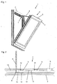
- a window 1 is shown with a hinged to a frame 2 wings 3.
- a drive 4 is arranged, wherein the drive unit 5 is arranged on the wing 3.
- the drive unit 5 has a drive motor, a transmission, a receiving area for an actuating element 6, for example a chain, and an electrical connection unit, which may also include a controller.
- the actuator 6 of the drive 4 extends between the drive unit 5 and arranged on the frame 2 console 7, which for the articulation of the drive 4 to the Frame 2 is used.
- the drive unit 5 is designed to push out the actuating element 6 for opening the window 1 from the drive unit 5 or to pull it into the drive unit 5 for closing.
- the bracket 7 is formed as an elongated flat material, which may be made of metal or plastic, for example.
- the console 7 has one or more recesses 9 for mounting the console 7 on the frame 2.
- the recesses 9 are each formed as a slot in which a fastener 10, for example, a screw is arranged, which engages in a thread in the frame 2 or in a frame 2 fixed threaded piece 11, to the longitudinal extent of their displacement sliding down the console 7th
- a possibly present web 13 in the profile of the window frame 2 is removed, for example milled off, whereby the bracket 7, at least with its flat longitudinal extent, outside between the profile of the window frame 2 and the profile of the sash 3 for the arrangement the drive unit 5 available receiving space is arranged.
- the console 7 can also have guide recesses 12 for guiding the longitudinal displacement, in which parts of the web 13 of the profile of the window frame 2 engage.
- the web 13 is removed only in sections.
- the actuating element 6 has an end element 8, with which the actuating element 6 is releasably connected to the console 7 for emergency release.
- the console 7 has a receiving element 14 which is arranged at one end of the console 7 facing the end element 8 of the actuating element 6.
- the console 7 is displaceable between two positions, with a first position in Fig. 2 is shown, in which the actuating element 6 is not connected to the console 7.
- the Fig. 3 shows the second position, wherein the bracket 7 is displaced along its extent or the extent of the profile of the frame 2 in the direction of the actuating element 6 and the end member 8 and the receiving element 14 are at least almost to each other.
- the positioning the console 7 on the frame 2 is carried out in dependence on the position of the drive unit 5 on the wing 3, so that the end element 8 is located next to the receiving element 14.
- a connecting element 15 is selectively inserted into a bore in the end element 8 or in the receiving element 14.
- a connecting element 15 may already be fixed on one side to the end element 8 or on the receiving element 14 or be formed in one piece with the respective element.
- the end element 8 and the receiving element 14 will be correspondingly Fig. 2 facing each other so that engages by moving the console 7 in its second position, the connecting element 15 in the corresponding bore of end member 8 and receiving element 14.
- the connecting element is first inserted into the end element 8.
- the connecting element 15 engages in the displacement of the console 7 in the receiving element 14, whereby the actuating element 6 is coupled to the console 7.
- the position after the shift to the second position is in Fig. 3 shown, wherein the connecting pin 15 is disposed both in the end piece 8 and in the receiving piece 14.
- the connecting pin 15 may have for securing in the bore of the end member 8 or the receiving element 14 in an annular groove into which a spring ring or an O-ring can be used.
- the spring ring is received during insertion of the connecting element 15 in one of the holes in the initial region of the holes. This ensures that the connecting pin 15 is held with a certain, determined by the bias of the spring ring force in the bore.
- a sliding element 16 is further arranged, by means of which the console 7 is displaceable along its extension.
- the sliding element 16 is arranged so that it is accessible from outside the window 1 with the window closed 1, wherein the wing 3 rests on the frame 2.
- Fig. 4 is a section through the window 1 in the upper region of the frame 2 and the wing 3, in which the drive 4 is arranged, shown.
- the console 7 has a flat longitudinal extent, which extends between the actuating element 6 and the sliding member 16.
- the sliding element 16 itself is structurally arranged in the end region or integrally formed, and is located outside the arrangement region of the drive unit 5.
- the console 7 is arranged with its flat longitudinal extent within the profile of the frame 2, wherein a possibly existing web 13 at least partially is removed.
- the longitudinal extent of the console 7 is selected so that the constructively arranged sliding element 16 outside the arrangement region of the drive unit 5, in Fig. 4 behind it, is located.
- the actuating element 6 can be detached from its connection to the window frame 2 in a non-destructive manner by using any flat means, for example a flat tool, as the blade of a screwdriver is engaged in the gap 17 between the frame 2 and the wing 3 and the console 7 on the sliding element 16 engaging in the in Fig. 2 moved position is shown.
- any flat means for example a flat tool
- the connecting element 15 depending on the design, pulled out of the end member 8 or the receiving element 14, whereby the actuator 6 is released and the wing 3 manually released from the frame 2 and that window can be opened.
Claims (7)
- Dispositif de déverrouillage d'une fenêtre (1), d'un volet ou analogue, comprenant un battant (3) supporté de manière pivotante sur un châssis dormant (2), le dispositif présentant un entraînement (4), avec une unité d'entraînement (5) et un élément d'actionnement (6) qui s'étend entre l'unité d'entraînement (5) et une console (7), l'unité d'entraînement (5) étant disposée au niveau du châssis dormant (2) ou du battant (3) et la console (7) étant disposée au niveau du battant (3) ou du châssis dormant (2), la console (7) présentant une étendue longitudinale essentiellement plane et pouvant être déplacée le long de cette étendue entre une première position et une deuxième position pour l'accouplement libérable de l'élément d'actionnement (6) de l'unité d'entraînement (5) avec la console (7), caractérisé en ce
qu'un élément coulissant (16) disposé en appui est disposé au niveau de l'étendue longitudinale plate de la console (7), au moyen duquel élément coulissant la console (7) peut être déplacée le long de son étendue, l'élément coulissant (16), lorsque la fenêtre (1) est fermée, faisant saillie dans une région en dessous d'une fente (17) entre le châssis dormant (2) et le battant (3), et, lorsque la fenêtre (1) est fermée, pouvant être déplacé longitudinalement à travers la fente (17) entre le châssis dormant (2) et le battant (3), de sorte que pour le déverrouillage de la fenêtre (1), l'élément d'actionnement (6) puisse être libéré de la console (7) depuis l'extérieur de la fenêtre (1). - Dispositif selon la revendication 1, caractérisé en ce que l'étendue longitudinale plate de la console (7) est disposée à l'intérieur du profilé du châssis dormant (2) ou du battant (3) et se trouve à l'extérieur de la région d'agencement de l'unité d'entraînement (5).
- Dispositif selon la revendication 1, caractérisé en ce que l'élément coulissant (16) est disposé latéralement à l'extérieur de la région d'agencement de l'unité d'entraînement (5) à côté de l'unité d'entraînement (5).
- Dispositif selon la revendication 1, caractérisé en ce qu'un élément d'extrémité (8) est disposé au niveau de l'élément d'actionnement (6).
- Dispositif selon la revendication 1, caractérisé en ce qu'un élément de réception (14) est disposé au niveau de la console (7).
- Dispositif selon les revendications 4 et 5, caractérisé en ce que pour la connexion libérable de l'élément d'actionnement (6) avec la console (7), l'élément d'extrémité (8) et l'élément de réception (14) peuvent être accouplés au moyen d'un élément de connexion (15).
- Dispositif selon la revendication 6, caractérisé en ce que l'accouplement de l'élément d'extrémité (8) avec l'élément de réception (14) s'effectue au moyen de l'élément de connexion (15) par le mouvement de déplacement de la console (7).
Priority Applications (1)
| Application Number | Priority Date | Filing Date | Title |
|---|---|---|---|
| PL11157133T PL2365176T3 (pl) | 2010-03-12 | 2011-03-07 | Urządzenie do odblokowywania okna, pokrywy lub tym podobnych |
Applications Claiming Priority (1)
| Application Number | Priority Date | Filing Date | Title |
|---|---|---|---|
| DE102010002815A DE102010002815B4 (de) | 2010-03-12 | 2010-03-12 | Vorrichtung zur Entriegelung eines Fensters, einer Klappe oder dergleichen |
Publications (3)
| Publication Number | Publication Date |
|---|---|
| EP2365176A2 EP2365176A2 (fr) | 2011-09-14 |
| EP2365176A3 EP2365176A3 (fr) | 2014-08-06 |
| EP2365176B1 true EP2365176B1 (fr) | 2016-08-17 |
Family
ID=44121698
Family Applications (1)
| Application Number | Title | Priority Date | Filing Date |
|---|---|---|---|
| EP11157133.7A Active EP2365176B1 (fr) | 2010-03-12 | 2011-03-07 | Dispositif de déverrouillage d'une fenêtre, d'un battant ou analogue |
Country Status (3)
| Country | Link |
|---|---|
| EP (1) | EP2365176B1 (fr) |
| DE (1) | DE102010002815B4 (fr) |
| PL (1) | PL2365176T3 (fr) |
Families Citing this family (3)
| Publication number | Priority date | Publication date | Assignee | Title |
|---|---|---|---|---|
| DE102011053767A1 (de) * | 2011-09-20 | 2013-03-21 | SCHÜCO International KG | Fenster oder Tür |
| DE102017220244A1 (de) * | 2017-11-14 | 2019-05-16 | Geze Gmbh | Modulare Antriebsvorrichtung |
| DE102019007008A1 (de) * | 2019-10-09 | 2021-04-15 | Siegenia-Aubi Kg | Ausstellvorrichtung für ein Dreh-Kipp-Flügel eines Fensters oder einer Tür |
Family Cites Families (5)
| Publication number | Priority date | Publication date | Assignee | Title |
|---|---|---|---|---|
| DE4304108C2 (de) * | 1993-02-11 | 1997-06-19 | Klemens Schlachter | Vorrichtung zum mechanischen Öffnen und Schließen von Fenstern mit verdecktem Beschlag |
| DE10162972A1 (de) * | 2001-12-20 | 2003-07-10 | Esco Metallbaubeschlag Handel Gmbh | Motorische Stellvorrichtung für Fenster, Türen oder dergleichen mit zumindest einem Dreh/Kipp-Flügel |
| DE102004031212B3 (de) | 2004-06-28 | 2005-06-30 | Geze Gmbh | Flügel in einem Blendrahmen mit einem Antrieb |
| DE102004038869A1 (de) * | 2004-08-10 | 2006-02-23 | Hydro Building Systems Gmbh | Kipp- und/oder Drehvorrichtung für ein Fenster, eine Tür, eine Fenstertür oder dergleichen |
| ITMI20072365A1 (it) * | 2007-12-18 | 2009-06-19 | Master Srl | "sistema di aggancio/sgancio di un elemento attuatore ad un'anta di un infisso" |
-
2010
- 2010-03-12 DE DE102010002815A patent/DE102010002815B4/de not_active Withdrawn - After Issue
-
2011
- 2011-03-07 PL PL11157133T patent/PL2365176T3/pl unknown
- 2011-03-07 EP EP11157133.7A patent/EP2365176B1/fr active Active
Also Published As
| Publication number | Publication date |
|---|---|
| DE102010002815B4 (de) | 2013-09-12 |
| EP2365176A3 (fr) | 2014-08-06 |
| DE102010002815A1 (de) | 2011-09-15 |
| PL2365176T3 (pl) | 2017-07-31 |
| EP2365176A2 (fr) | 2011-09-14 |
Similar Documents
| Publication | Publication Date | Title |
|---|---|---|
| EP3620602B1 (fr) | Dispositif d'ouverture et / ou de fermeture, ainsi que de verrouillage d'un état fermé d'un agencement de fermeture, de fermeture d'une ouverture de chambre, ainsi qu'agencement de fermeture doté d'un tel dispositif | |
| DE102008048994A1 (de) | Feststellvorrichtung für einen Flügel einer Tür | |
| DE202012101391U1 (de) | Flügelseitiger Drehflügeltürantriebsanschluss, soweit damit versehene Drehflügeltürantriebsvorrichtung und Drehflügel | |
| EP2365176B1 (fr) | Dispositif de déverrouillage d'une fenêtre, d'un battant ou analogue | |
| EP2146032B1 (fr) | Dispositif destiné à ouvrir et/ou fermer ainsi qu'à verrouiller un état fermé d'un dispositif de fermeture destiné à fermer une ouverture de salle ainsi que dispositif de fermeture doté d'un tel dispositif | |
| EP2009215B1 (fr) | Dispositif de détection pour un dispositif d'entraînement des portes ou fenêtres | |
| EP1746235B1 (fr) | Ensemble de ferrure | |
| EP1813754B1 (fr) | Ferme-porte | |
| DE102009050549B4 (de) | Betätigungsvorrichtung zum Öffnen und Schließen eines Fensters, einer Klappe oder dergleichen | |
| EP2505744A2 (fr) | Plaque de fermeture pour un battant de porte ou de fenêtre déposé d'un dormant | |
| DE10252884A1 (de) | Treibstangenbeschlag für einen unterschlagenden Flügel eines zweiflügeligen, setzholzlosen Fensters oder Tür mit einem Treibstangenantrieb | |
| EP2343422B1 (fr) | Bloc d'armature pour une fenêtre, une porte, un clapet ou analogue | |
| DE102014111131A1 (de) | Vorrichtung zur Ver- und Entriegelung eines Fensterflügels, einer Lüftungsklappe oder dergleichen an einem Blendrahmen | |
| DE102007010209B4 (de) | Antriebsvorrichtung | |
| DE102014117419A1 (de) | Beschlag für Fenster, Türen und dergleichen und Getriebeeinheit für einen solchen Beschlag | |
| EP1936085B1 (fr) | Armatures pour fenêtres, portes ou analogues | |
| DE10015095A1 (de) | Verriegelungsvorrichtung für einen Türflügel | |
| EP2532816B1 (fr) | Dispositif d'entraînement pour une armature de bielle | |
| EP1580371B1 (fr) | Ensemble ferrure | |
| DE102004060501B4 (de) | Vorrichtung zur Positionierung eines Teiles | |
| EP4219870A1 (fr) | Crochet d'arrêt et dispositif de retenue comprenant un tel crochet d'arrêt | |
| EP2835487A1 (fr) | Dispositif de battant d'un bâtiment | |
| DE19702004C2 (de) | Handbetätigungsvorrichtung für die zu einer Horizontalschiebewand gehörenden Teilelemente und Verfahren zur Handbetätigung dieser Teilelemente | |
| WO2001071134A1 (fr) | Ferrure de vasistas, notamment sur caravanes, camping-cars et vehicules similaires | |
| DE10360036A1 (de) | Vorrichtung zur Schließfolgeregelung |
Legal Events
| Date | Code | Title | Description |
|---|---|---|---|
| PUAI | Public reference made under article 153(3) epc to a published international application that has entered the european phase |
Free format text: ORIGINAL CODE: 0009012 |
|
| AK | Designated contracting states |
Kind code of ref document: A2 Designated state(s): AL AT BE BG CH CY CZ DE DK EE ES FI FR GB GR HR HU IE IS IT LI LT LU LV MC MK MT NL NO PL PT RO RS SE SI SK SM TR |
|
| AX | Request for extension of the european patent |
Extension state: BA ME |
|
| PUAL | Search report despatched |
Free format text: ORIGINAL CODE: 0009013 |
|
| AK | Designated contracting states |
Kind code of ref document: A3 Designated state(s): AL AT BE BG CH CY CZ DE DK EE ES FI FR GB GR HR HU IE IS IT LI LT LU LV MC MK MT NL NO PL PT RO RS SE SI SK SM TR |
|
| AX | Request for extension of the european patent |
Extension state: BA ME |
|
| RIC1 | Information provided on ipc code assigned before grant |
Ipc: E05F 15/12 20060101AFI20140629BHEP |
|
| 17P | Request for examination filed |
Effective date: 20150203 |
|
| RBV | Designated contracting states (corrected) |
Designated state(s): AL AT BE BG CH CY CZ DE DK EE ES FI FR GB GR HR HU IE IS IT LI LT LU LV MC MK MT NL NO PL PT RO RS SE SI SK SM TR |
|
| REG | Reference to a national code |
Ref country code: DE Ref legal event code: R079 Ref document number: 502011010406 Country of ref document: DE Free format text: PREVIOUS MAIN CLASS: E05F0015120000 Ipc: E05F0015619000 |
|
| RIC1 | Information provided on ipc code assigned before grant |
Ipc: E05F 15/619 20150101AFI20160317BHEP |
|
| GRAP | Despatch of communication of intention to grant a patent |
Free format text: ORIGINAL CODE: EPIDOSNIGR1 |
|
| INTG | Intention to grant announced |
Effective date: 20160502 |
|
| GRAS | Grant fee paid |
Free format text: ORIGINAL CODE: EPIDOSNIGR3 |
|
| GRAA | (expected) grant |
Free format text: ORIGINAL CODE: 0009210 |
|
| AK | Designated contracting states |
Kind code of ref document: B1 Designated state(s): AL AT BE BG CH CY CZ DE DK EE ES FI FR GB GR HR HU IE IS IT LI LT LU LV MC MK MT NL NO PL PT RO RS SE SI SK SM TR |
|
| REG | Reference to a national code |
Ref country code: GB Ref legal event code: FG4D Free format text: NOT ENGLISH |
|
| REG | Reference to a national code |
Ref country code: CH Ref legal event code: EP |
|
| REG | Reference to a national code |
Ref country code: IE Ref legal event code: FG4D Free format text: LANGUAGE OF EP DOCUMENT: GERMAN |
|
| REG | Reference to a national code |
Ref country code: AT Ref legal event code: REF Ref document number: 821279 Country of ref document: AT Kind code of ref document: T Effective date: 20160915 |
|
| REG | Reference to a national code |
Ref country code: DE Ref legal event code: R096 Ref document number: 502011010406 Country of ref document: DE |
|
| REG | Reference to a national code |
Ref country code: SE Ref legal event code: TRGR |
|
| REG | Reference to a national code |
Ref country code: NL Ref legal event code: MP Effective date: 20160817 |
|
| REG | Reference to a national code |
Ref country code: LT Ref legal event code: MG4D |
|
| REG | Reference to a national code |
Ref country code: NO Ref legal event code: T2 Effective date: 20160817 |
|
| PG25 | Lapsed in a contracting state [announced via postgrant information from national office to epo] |
Ref country code: IT Free format text: LAPSE BECAUSE OF FAILURE TO SUBMIT A TRANSLATION OF THE DESCRIPTION OR TO PAY THE FEE WITHIN THE PRESCRIBED TIME-LIMIT Effective date: 20160817 Ref country code: NL Free format text: LAPSE BECAUSE OF FAILURE TO SUBMIT A TRANSLATION OF THE DESCRIPTION OR TO PAY THE FEE WITHIN THE PRESCRIBED TIME-LIMIT Effective date: 20160817 Ref country code: RS Free format text: LAPSE BECAUSE OF FAILURE TO SUBMIT A TRANSLATION OF THE DESCRIPTION OR TO PAY THE FEE WITHIN THE PRESCRIBED TIME-LIMIT Effective date: 20160817 Ref country code: FI Free format text: LAPSE BECAUSE OF FAILURE TO SUBMIT A TRANSLATION OF THE DESCRIPTION OR TO PAY THE FEE WITHIN THE PRESCRIBED TIME-LIMIT Effective date: 20160817 Ref country code: HR Free format text: LAPSE BECAUSE OF FAILURE TO SUBMIT A TRANSLATION OF THE DESCRIPTION OR TO PAY THE FEE WITHIN THE PRESCRIBED TIME-LIMIT Effective date: 20160817 Ref country code: LT Free format text: LAPSE BECAUSE OF FAILURE TO SUBMIT A TRANSLATION OF THE DESCRIPTION OR TO PAY THE FEE WITHIN THE PRESCRIBED TIME-LIMIT Effective date: 20160817 |
|
| PG25 | Lapsed in a contracting state [announced via postgrant information from national office to epo] |
Ref country code: PT Free format text: LAPSE BECAUSE OF FAILURE TO SUBMIT A TRANSLATION OF THE DESCRIPTION OR TO PAY THE FEE WITHIN THE PRESCRIBED TIME-LIMIT Effective date: 20161219 Ref country code: ES Free format text: LAPSE BECAUSE OF FAILURE TO SUBMIT A TRANSLATION OF THE DESCRIPTION OR TO PAY THE FEE WITHIN THE PRESCRIBED TIME-LIMIT Effective date: 20160817 Ref country code: GR Free format text: LAPSE BECAUSE OF FAILURE TO SUBMIT A TRANSLATION OF THE DESCRIPTION OR TO PAY THE FEE WITHIN THE PRESCRIBED TIME-LIMIT Effective date: 20161118 Ref country code: LV Free format text: LAPSE BECAUSE OF FAILURE TO SUBMIT A TRANSLATION OF THE DESCRIPTION OR TO PAY THE FEE WITHIN THE PRESCRIBED TIME-LIMIT Effective date: 20160817 |
|
| REG | Reference to a national code |
Ref country code: FR Ref legal event code: PLFP Year of fee payment: 7 |
|
| PG25 | Lapsed in a contracting state [announced via postgrant information from national office to epo] |
Ref country code: EE Free format text: LAPSE BECAUSE OF FAILURE TO SUBMIT A TRANSLATION OF THE DESCRIPTION OR TO PAY THE FEE WITHIN THE PRESCRIBED TIME-LIMIT Effective date: 20160817 Ref country code: RO Free format text: LAPSE BECAUSE OF FAILURE TO SUBMIT A TRANSLATION OF THE DESCRIPTION OR TO PAY THE FEE WITHIN THE PRESCRIBED TIME-LIMIT Effective date: 20160817 |
|
| REG | Reference to a national code |
Ref country code: DE Ref legal event code: R097 Ref document number: 502011010406 Country of ref document: DE |
|
| PG25 | Lapsed in a contracting state [announced via postgrant information from national office to epo] |
Ref country code: SK Free format text: LAPSE BECAUSE OF FAILURE TO SUBMIT A TRANSLATION OF THE DESCRIPTION OR TO PAY THE FEE WITHIN THE PRESCRIBED TIME-LIMIT Effective date: 20160817 Ref country code: CZ Free format text: LAPSE BECAUSE OF FAILURE TO SUBMIT A TRANSLATION OF THE DESCRIPTION OR TO PAY THE FEE WITHIN THE PRESCRIBED TIME-LIMIT Effective date: 20160817 Ref country code: SM Free format text: LAPSE BECAUSE OF FAILURE TO SUBMIT A TRANSLATION OF THE DESCRIPTION OR TO PAY THE FEE WITHIN THE PRESCRIBED TIME-LIMIT Effective date: 20160817 Ref country code: BG Free format text: LAPSE BECAUSE OF FAILURE TO SUBMIT A TRANSLATION OF THE DESCRIPTION OR TO PAY THE FEE WITHIN THE PRESCRIBED TIME-LIMIT Effective date: 20161117 Ref country code: DK Free format text: LAPSE BECAUSE OF FAILURE TO SUBMIT A TRANSLATION OF THE DESCRIPTION OR TO PAY THE FEE WITHIN THE PRESCRIBED TIME-LIMIT Effective date: 20160817 |
|
| PLBE | No opposition filed within time limit |
Free format text: ORIGINAL CODE: 0009261 |
|
| STAA | Information on the status of an ep patent application or granted ep patent |
Free format text: STATUS: NO OPPOSITION FILED WITHIN TIME LIMIT |
|
| 26N | No opposition filed |
Effective date: 20170518 |
|
| PG25 | Lapsed in a contracting state [announced via postgrant information from national office to epo] |
Ref country code: SI Free format text: LAPSE BECAUSE OF FAILURE TO SUBMIT A TRANSLATION OF THE DESCRIPTION OR TO PAY THE FEE WITHIN THE PRESCRIBED TIME-LIMIT Effective date: 20160817 |
|
| REG | Reference to a national code |
Ref country code: CH Ref legal event code: PL |
|
| PG25 | Lapsed in a contracting state [announced via postgrant information from national office to epo] |
Ref country code: MC Free format text: LAPSE BECAUSE OF FAILURE TO SUBMIT A TRANSLATION OF THE DESCRIPTION OR TO PAY THE FEE WITHIN THE PRESCRIBED TIME-LIMIT Effective date: 20160817 |
|
| REG | Reference to a national code |
Ref country code: IE Ref legal event code: MM4A |
|
| PG25 | Lapsed in a contracting state [announced via postgrant information from national office to epo] |
Ref country code: LU Free format text: LAPSE BECAUSE OF NON-PAYMENT OF DUE FEES Effective date: 20170307 |
|
| PG25 | Lapsed in a contracting state [announced via postgrant information from national office to epo] |
Ref country code: CH Free format text: LAPSE BECAUSE OF NON-PAYMENT OF DUE FEES Effective date: 20170331 Ref country code: LI Free format text: LAPSE BECAUSE OF NON-PAYMENT OF DUE FEES Effective date: 20170331 Ref country code: IE Free format text: LAPSE BECAUSE OF NON-PAYMENT OF DUE FEES Effective date: 20170307 |
|
| REG | Reference to a national code |
Ref country code: BE Ref legal event code: MM Effective date: 20170331 |
|
| REG | Reference to a national code |
Ref country code: FR Ref legal event code: PLFP Year of fee payment: 8 |
|
| PG25 | Lapsed in a contracting state [announced via postgrant information from national office to epo] |
Ref country code: BE Free format text: LAPSE BECAUSE OF NON-PAYMENT OF DUE FEES Effective date: 20170331 |
|
| PG25 | Lapsed in a contracting state [announced via postgrant information from national office to epo] |
Ref country code: MT Free format text: LAPSE BECAUSE OF FAILURE TO SUBMIT A TRANSLATION OF THE DESCRIPTION OR TO PAY THE FEE WITHIN THE PRESCRIBED TIME-LIMIT Effective date: 20160817 |
|
| PG25 | Lapsed in a contracting state [announced via postgrant information from national office to epo] |
Ref country code: AL Free format text: LAPSE BECAUSE OF FAILURE TO SUBMIT A TRANSLATION OF THE DESCRIPTION OR TO PAY THE FEE WITHIN THE PRESCRIBED TIME-LIMIT Effective date: 20160817 |
|
| PG25 | Lapsed in a contracting state [announced via postgrant information from national office to epo] |
Ref country code: HU Free format text: LAPSE BECAUSE OF FAILURE TO SUBMIT A TRANSLATION OF THE DESCRIPTION OR TO PAY THE FEE WITHIN THE PRESCRIBED TIME-LIMIT; INVALID AB INITIO Effective date: 20110307 |
|
| PG25 | Lapsed in a contracting state [announced via postgrant information from national office to epo] |
Ref country code: CY Free format text: LAPSE BECAUSE OF NON-PAYMENT OF DUE FEES Effective date: 20160817 |
|
| PG25 | Lapsed in a contracting state [announced via postgrant information from national office to epo] |
Ref country code: MK Free format text: LAPSE BECAUSE OF FAILURE TO SUBMIT A TRANSLATION OF THE DESCRIPTION OR TO PAY THE FEE WITHIN THE PRESCRIBED TIME-LIMIT Effective date: 20160817 |
|
| PG25 | Lapsed in a contracting state [announced via postgrant information from national office to epo] |
Ref country code: TR Free format text: LAPSE BECAUSE OF FAILURE TO SUBMIT A TRANSLATION OF THE DESCRIPTION OR TO PAY THE FEE WITHIN THE PRESCRIBED TIME-LIMIT Effective date: 20160817 |
|
| PG25 | Lapsed in a contracting state [announced via postgrant information from national office to epo] |
Ref country code: IS Free format text: LAPSE BECAUSE OF FAILURE TO SUBMIT A TRANSLATION OF THE DESCRIPTION OR TO PAY THE FEE WITHIN THE PRESCRIBED TIME-LIMIT Effective date: 20161217 |
|
| PGFP | Annual fee paid to national office [announced via postgrant information from national office to epo] |
Ref country code: NO Payment date: 20230324 Year of fee payment: 13 Ref country code: FR Payment date: 20230322 Year of fee payment: 13 Ref country code: AT Payment date: 20230322 Year of fee payment: 13 |
|
| PGFP | Annual fee paid to national office [announced via postgrant information from national office to epo] |
Ref country code: SE Payment date: 20230314 Year of fee payment: 13 Ref country code: PL Payment date: 20230228 Year of fee payment: 13 Ref country code: GB Payment date: 20230321 Year of fee payment: 13 |
|
| PGFP | Annual fee paid to national office [announced via postgrant information from national office to epo] |
Ref country code: AT Payment date: 20240321 Year of fee payment: 14 |
|
| PGFP | Annual fee paid to national office [announced via postgrant information from national office to epo] |
Ref country code: DE Payment date: 20240331 Year of fee payment: 14 |