EP1936085B1 - Armatures pour fenêtres, portes ou analogues - Google Patents
Armatures pour fenêtres, portes ou analogues Download PDFInfo
- Publication number
- EP1936085B1 EP1936085B1 EP06026862A EP06026862A EP1936085B1 EP 1936085 B1 EP1936085 B1 EP 1936085B1 EP 06026862 A EP06026862 A EP 06026862A EP 06026862 A EP06026862 A EP 06026862A EP 1936085 B1 EP1936085 B1 EP 1936085B1
- Authority
- EP
- European Patent Office
- Prior art keywords
- guide
- plate
- fitting
- sliding
- fitting according
- Prior art date
- Legal status (The legal status is an assumption and is not a legal conclusion. Google has not performed a legal analysis and makes no representation as to the accuracy of the status listed.)
- Not-in-force
Links
- 238000005452 bending Methods 0.000 description 8
- 230000008901 benefit Effects 0.000 description 3
- 238000009434 installation Methods 0.000 description 2
- 238000010276 construction Methods 0.000 description 1
- 230000001747 exhibiting effect Effects 0.000 description 1
- 230000005484 gravity Effects 0.000 description 1
- 238000004519 manufacturing process Methods 0.000 description 1
Images


Classifications
-
- E—FIXED CONSTRUCTIONS
- E05—LOCKS; KEYS; WINDOW OR DOOR FITTINGS; SAFES
- E05D—HINGES OR SUSPENSION DEVICES FOR DOORS, WINDOWS OR WINGS
- E05D15/00—Suspension arrangements for wings
- E05D15/28—Suspension arrangements for wings supported on arms movable in horizontal plane
- E05D15/30—Suspension arrangements for wings supported on arms movable in horizontal plane with pivoted arms and sliding guides
-
- E—FIXED CONSTRUCTIONS
- E05—LOCKS; KEYS; WINDOW OR DOOR FITTINGS; SAFES
- E05D—HINGES OR SUSPENSION DEVICES FOR DOORS, WINDOWS OR WINGS
- E05D15/00—Suspension arrangements for wings
- E05D15/48—Suspension arrangements for wings allowing alternative movements
- E05D15/52—Suspension arrangements for wings allowing alternative movements for opening about a vertical as well as a horizontal axis
- E05D15/5211—Concealed suspension fittings
-
- E—FIXED CONSTRUCTIONS
- E05—LOCKS; KEYS; WINDOW OR DOOR FITTINGS; SAFES
- E05D—HINGES OR SUSPENSION DEVICES FOR DOORS, WINDOWS OR WINGS
- E05D15/00—Suspension arrangements for wings
- E05D15/48—Suspension arrangements for wings allowing alternative movements
- E05D15/52—Suspension arrangements for wings allowing alternative movements for opening about a vertical as well as a horizontal axis
- E05D15/5214—Corner supports
-
- E—FIXED CONSTRUCTIONS
- E05—LOCKS; KEYS; WINDOW OR DOOR FITTINGS; SAFES
- E05Y—INDEXING SCHEME ASSOCIATED WITH SUBCLASSES E05D AND E05F, RELATING TO CONSTRUCTION ELEMENTS, ELECTRIC CONTROL, POWER SUPPLY, POWER SIGNAL OR TRANSMISSION, USER INTERFACES, MOUNTING OR COUPLING, DETAILS, ACCESSORIES, AUXILIARY OPERATIONS NOT OTHERWISE PROVIDED FOR, APPLICATION THEREOF
- E05Y2600/00—Mounting or coupling arrangements for elements provided for in this subclass
- E05Y2600/40—Mounting location; Visibility of the elements
- E05Y2600/41—Concealed
-
- E—FIXED CONSTRUCTIONS
- E05—LOCKS; KEYS; WINDOW OR DOOR FITTINGS; SAFES
- E05Y—INDEXING SCHEME ASSOCIATED WITH SUBCLASSES E05D AND E05F, RELATING TO CONSTRUCTION ELEMENTS, ELECTRIC CONTROL, POWER SUPPLY, POWER SIGNAL OR TRANSMISSION, USER INTERFACES, MOUNTING OR COUPLING, DETAILS, ACCESSORIES, AUXILIARY OPERATIONS NOT OTHERWISE PROVIDED FOR, APPLICATION THEREOF
- E05Y2900/00—Application of doors, windows, wings or fittings thereof
- E05Y2900/10—Application of doors, windows, wings or fittings thereof for buildings or parts thereof
- E05Y2900/13—Type of wing
- E05Y2900/132—Doors
Definitions
- the invention relates to a fitting for a window, a door or the like.
- a fitting part which has a guide, and a first tab, which is connected to a slider which is guided in the guide, wherein the guide has at least one lateral effetsgleit Chemistry along which the slider slides during a movement of the tab (see DE 20 2006 003 177 U1 and EP 1 612 356 A2 ).
- the sash weight must be absorbed by the concealed fitting.
- the wing must first be opened for opening from the fixed frame so that there is no collision between the rollover and the frame when the wing is opened.
- a scissors geometry must be provided so that a parking of the wing is even possible.
- Object of the present invention is to develop a fitting such that it can be made small on a small building, low Has wear and can accommodate the other wing loads with a small size.
- the fitting can be designed as a so-called Axerlager or corner bearing.
- An axle bearing serves to connect the frame and sash in an upper area and the corner bearing serves to connect the frame and the sash in a lower area of the frame.
- the guide has two guide sliding surfaces and that the slider has two sliding surfaces, which are each tuned to a mecanicsgleit phenomenon.
- the slider is guided on two opposite surfaces. This increases the stability of the fitting.
- An embodiment is characterized in that the slider is rotatably connected to the first tab.
- a particularly compact embodiment of the fitting results when the guide is formed bent and / or is aligned obliquely to a longitudinal direction of the fitting part. This is advantageous in particular for a concealed fitting.
- the guide has an undercut and the slider has a head portion with which it engages behind the guide in the region of the undercut.
- the guide may be T-shaped in cross-section. Because the slider with its head portion engages behind the guide in the region of the undercut, the slider is securely held on the guide. Forces generated by a wing acting on the slider can be absorbed without the slider becoming detached from the guide.
- the slider may be formed as Gleitniet.
- a Gleitniet consists of only one part and is therefore cheaper to manufacture and in the assembly as a two-piece glider.
- a two-piece slider sliding element and Befest Trentsniet
- the disadvantage lies in the fact that the two-piece glider is more expensive, since it consists of two parts and are mounted and joined in an additional operation got to.
- the sliding element breaks when the lateral forces are too great or the fastening rivet can be pulled out of the sliding element if the axial force is too great.
- the problem of the two-piece slider becomes greater the smaller the components (slider and fastener) become and the larger the forces that act.
- the slide rivet has at its end to be fastened to the tab an alignment aid which is adapted to an alignment aid of the tab.
- the slider has an alignment surface that cooperates with a corresponding surface or line of the tab.
- the contour of the slide rivet can be matched to the contour of a passage opening of the tab, so that the slider can be introduced into the tab only in the position predetermined by the contours. This can be avoided that wedges the slider in the guide and it comes to failure of the assembly.
- the slide rivet has an assembly aid, via which the slide rivet can be aligned in a riveting tool.
- the mounting aid is advantageously designed as a notch.
- the slide rivet can be aligned in the riveting tool. This ensures that the Gleitniet sits properly in the rivet and the joining of the components is simplified.
- a particularly good connection of the slider with the tab results when the slider is materially connected to the tab. This ensures a particularly good and secure mounting of the slider the tab secured. In this case, the slider can be expressed from the tab, pronounced or molded on it.
- a second tab may be provided, which is pivotally connected to the first tab and the fitting part. Through the two tabs a scissor geometry can be realized, which allows exhibiting a wing.
- one of the tabs can be used to remove at least a portion, preferably the entire weight of a wing.
- the second tab may be made smaller in thickness if used exclusively or predominantly as a control tab. The fact that one tab is thinner than the other, the total height of folded tabs can be reduced, which is particularly advantageous for concealed fittings.
- the first tab has a Eckbandability, in particular a support pin has. This allows the weight of the wing to be transferred to the first tab.
- the first tab in turn rests on the second tab formed as a support tab and thus transfers the load to the support tab.
- the scissors geometry formed by the tabs is preferably chosen so that there is the greatest possible overlap of the control tab and the support tab. Thus, a resulting bending moment is kept low. This in turn spares the connection formed by the slider and the guide.
- a compact construction of the fitting is made possible when a downwardly directed load-receiving device is provided.
- Such a load-bearing device is therefore advantageous because it does not have to be accommodated in the rabbet area between the frame and wing.
- the second tab is designed as a support tab and the fitting part as a base plate fastened to a frame, wherein the base plate has at least a portion of the load receiving device.
- the base plate has a downwardly directed sleeve in which a downwardly directed support pin of the support lug is rotatably arranged.
- the support tab can initiate the resulting bending moment on the support pin in the sleeve.
- the support bracket is firmly connected to the support bolt.
- the sleeve which is fixedly connected to the base plate, serves as an abutment to the occurring bending moment, which is introduced via the support bracket and the support bolt.
- the sleeve and the support bolt form a hinge.
- the pivotal connection of the fitting part and the second tab is realized.
- the distances between the support bolt, control tab and support pin significantly influence the resulting bending moment. Therefore, these are to be kept as small as possible in order to minimize the bending moment.
- the forces are transmitted to the base plate via the sleeve. This directs the forces on the screw in the frame.
- the forces in the base plate are influenced by the length of the sleeve and the support pin. These must therefore be selected accordingly for a sufficient load bearing.
- the scope of the invention also includes a window, a door or the like, with a fixed frame and / or at least one wing, comprising at least one fitting described above.
- FIG. 1 and 2 is designed as a corner bearing fitting 2 shown.
- This comprises a base part designed as a fitting part 5.
- a first tab 6 is pivotally connected to a second tab 7.
- the end 8 of the first tab 6 is displaceable along a guide 9 relative to the fitting part 5.
- the first tab 6 and the second tab 7 form a scissors geometry.
- the scissors geometry is designed so that the wing is turned off as little as possible and still creates the largest possible clear width.
- With the fitting part 5 designed as a support tab second tab 7 is pivotally connected.
- the fitting 2 as Axerlager the pivotal connection of the fitting part 5 can be solved. To open the wing of this is just turned off so far from the frame, that there is no collision hiss the flashover and the frame.
- the fitting 5 can be bolted to a frame.
- a corner band 10 is provided, with which the wing is supported on the first tab 6.
- a support pin 15 is from the first tab 6 from. On this support pin 15, the corner band sits 10. The support pin 15 forms a Eckbandage.
- the second tab 7 also has at its free end a bolt 16, which engages from below into the corner band 10. The weight of the wing is transmitted via the corner band 10 on the support pin 15. This then transmits the weight on the first tab 6.
- the first tab 6 rests on the second tab 7 and thus transmits the load on the second tab 7.
- the scissor geometry was chosen so that the greatest possible overlap of the first flap 6 and the second flap 7 is present with the wing open. Thus, a resulting bending moment is kept small.
- the second tab 7 must absorb a larger load than the first tab 6. Therefore, the second tab 7 is formed thicker than the first tab. 6
- the guide 9 is executed bent. Through the ends of the guide 9, the movement of the first tab 6 is limited relative to the fitting part 5.
- the fitting part 5 and the second tab 7 together form a load-receiving device 20.
- the fitting 5 has a downwardly extending sleeve 21, in which a support pin 22 which is fixedly connected to one end of the second tab 7 protrudes.
- the second tab 7 initiates the bending moment arising under the weight of the flared wing via the support bolt 22 into the sleeve 21.
- the sleeve 21 serves as an abutment to the occurring bending moment, which is introduced via the second tab 7 and the support pin 22.
- the sleeve 21 and the support pin 22 form a hinge.
- the forces occurring are transmitted to the fitting part 5 via the sleeve 21.
- This introduces the forces on the screw in the frame 1.
- the load-receiving device 20 projects downwards, in particular into the frame, the fitting 2 occupies only a small amount of space in the rebate air area.
- the first tab 6 endeavors to tip over the second tab 7.
- This force endeavors to pull the slider 25 out of the guide 9. Due to the gravity of the wing, a force component in the horizontal direction is also exerted on the slider 25 via the first tab 6.
- the slider 25 at the end, with which it protrudes into the first tab has an alignment aid 26 formed as an alignment surface.
- the breakthrough opening 27 of the first tab 6 also has an alignment aid.
- the breakthrough opening 27 is not circular, but has a contour which is adapted to the slider 25, which is formed in the exemplary embodiment as Geleitniet.
- the slider 25 is shown. It can be seen that the slider 25 has a head portion 30 which is formed larger than the neck 31 of the slider 25.
- the head portion 30 has a substantially square basic shape. However, the Gleit Korean moral 32,33 rounded, and thus matched to the guide 9. Furthermore, the slider 25 has a trained as a notch mounting aid 34. At the end of the neck 31, the alignment aid 26 can be seen.
- FIG. 4 is a plan view from below of the slider 27 is shown. In particular, the alignment aid 26 becomes clear again here.
- FIG. 5 The sectional view of FIG. 5 according to the line IV - IV of FIG. 4 it can be seen that the slider 25 is constructed stepwise.
- the step shape 37 corresponds to an inner contour of the guide.
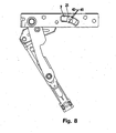
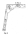
- FIGS. 6 to 9 the fitting 2 is shown with different opening positions.
- the FIG. 6 shows the position of the fitting 2 with the wing closed. In this position, the slider 25 is almost in an end position in the guide 9.
- the arrows 40,41 point to points of contact of Gleit Korean moral monax 32,33 with the chiefsgleit lake 42, 43.
- the guide 9 has an undercut 44, which is engaged behind by the head portion 30 of the slider 25. This ensures that the first tab 6 does not lift off the fitting part 5.
- FIG. 7 a first opening position of the wing is shown. This means that the second tab 7 is folded away from the fitting part 5. During this small opening movement is a shutdown of the wing.
- the arrows 40, 41 point again to points of contact of the surfaces 32, 33 with the surfaces 42, 43. It can be seen that now there are other points of contact than in the FIG. 6 , This means that the sliding surfaces 32, 33 of the slider 25 are adapted to the guide sliding surfaces 42, 43 such that the points of contact between the surfaces 32, 33, 42, 43 constantly change as the slider 25 moves in the guide 9.
Landscapes
- Engineering & Computer Science (AREA)
- Mechanical Engineering (AREA)
- Pens And Brushes (AREA)
- Curtains And Furnishings For Windows Or Doors (AREA)
- Liquid Crystal (AREA)
- Wing Frames And Configurations (AREA)
- Connection Of Plates (AREA)
- Hinges (AREA)
- Mechanical Pencils And Projecting And Retracting Systems Therefor, And Multi-System Writing Instruments (AREA)
- Support Devices For Sliding Doors (AREA)
Claims (17)
- Armature (2) pour une fenêtre, une porte ou objets analogues, comprenant une ferrure (5) munie d'un guide (9), et une première patte (6) reliée à un coulisseau (25) guidé dans le guide (9), ledit guide (9) présentant au moins une surface latérale (42, 43) de guidage par glissement, le long de laquelle ledit coulisseau (25) glisse lors d'un mouvement de la patte (6), caractérisée par le fait que la surface latérale (42, 43) de guidage par glissement, prévue au minimum, et une surface (32, 33) du coulisseau, glissant le long de ladite surface (42, 43) de guidage par glissement lors d'un mouvement de la patte (6), sont mutuellement coordonnées de telle sorte que, lors du mouvement le long de la surface (42, 43) de guidage par glissement, ladite surface (32, 33) du coulisseau porte dans différentes zones contre ladite surface (42, 43) de guidage par glissement.
- Armature selon la revendication 1, caractérisée par le fait que le guide (9) comprend deux surfaces (42, 43) de guidage par glissement, et le coulisseau (25) comprend deux surfaces (32, 33) respectivement coordonnées avec une surface (42, 43) de guidage par glissement.
- Armature selon la revendication 1 ou 2, caractérisée par le fait que le coulisseau (25) est relié à la patte (6) avec verrouillage rotatif.
- Armature selon l'une des revendications précédentes, caractérisée par le fait que le guide (9) est de réalisation curviligne, et/ou est orienté à l'oblique par rapport à une direction longitudinale de la ferrure (5).
- Armature selon l'une des revendications précédentes, caractérisée par le fait que le guide (9) présente une contre-dépouille, et le coulisseau (25) comporte une zone frontale (30) par laquelle il emprisonne ledit guide par-derrière dans la région de ladite contre-dépouille.
- Armature selon l'une des revendications précédentes, caractérisée par le fait que le coulisseau (25) est réalisé sous la forme d'un rivet de glissement.
- Armature selon l'une des revendications précédentes, caractérisée par le fait que le rivet de glissement présente, à son extrémité devant être fixée à la patte (6), un auxiliaire d'orientation (26) adapté à un auxiliaire d'orientation de ladite patte (6).
- Armature selon l'une des revendications précédentes, caractérisée par le fait que le rivet de glissement offre un auxiliaire de montage (34), par l'intermédiaire duquel ledit rivet de glissement peut être orienté dans un outil de rivetage.
- Armature selon l'une des revendications précédentes 1 à 5, caractérisée par le fait que le coulisseau (25) est relié matériellement à la patte (6).
- Armature selon la revendication 9, caractérisée par le fait que le coulisseau (25) est empreint ou embouti hors de la patte (6), ou fait corps avec cette dernière par moulage.
- Armature selon l'une des revendications précédentes, caractérisée par le fait qu'il est prévu une seconde patte (7) reliée, avec faculté de pivotement, à la première patte (6) et à la ferrure (5).
- Armature selon l'une des revendications précédentes, caractérisée par le fait qu'une patte (6, 7) est réalisée plus épaisse que l'autre.
- Armature selon l'une des revendications précédentes, caractérisée par le fait que la première patte (6) comporte un logement dédié à une réglette d'angle, en particulier un tenon de support (15).
- Armature selon l'une des revendications précédentes, caractérisée par la présence d'un système (20) d'absorption de charges, dirigé vers le bas.
- Armature selon l'une des revendications précédentes 11-14, caractérisée par le fait que la seconde patte (7) est réalisée sous la forme d'une patte de support, et la ferrure (5) est réalisée sous la forme d'une platine de base pouvant être fixée à un cadre, ladite platine de base présentant au moins une partie du système (20) d'absorption de charges.
- Armature selon l'une des revendications précédentes, caractérisée par le fait que la platine de base offre une douille (21) dirigée vers le bas et dans laquelle est logé, de manière rotative, un tenon d'appui (22) de la patte de support qui est dirigé vers le bas.
- Fenêtre, porte ou objet analogue comprenant un cadre fixe et/ou au moins un battant, comportant une armature (2) selon l'une des revendications précédentes.
Priority Applications (6)
| Application Number | Priority Date | Filing Date | Title |
|---|---|---|---|
| ES06026862T ES2322288T3 (es) | 2006-12-23 | 2006-12-23 | Herraje para ventanas, puertas o similares. |
| SI200630278T SI1936085T1 (sl) | 2006-12-23 | 2006-12-23 | Okov za okna, vrata in podobno |
| DE502006003211T DE502006003211D1 (de) | 2006-12-23 | 2006-12-23 | Beschlag für Fenster, Türen oder dgl. |
| PL06026862T PL1936085T3 (pl) | 2006-12-23 | 2006-12-23 | Okucie dla okien, drzwi lub tym podobnych |
| EP06026862A EP1936085B1 (fr) | 2006-12-23 | 2006-12-23 | Armatures pour fenêtres, portes ou analogues |
| AT06026862T ATE426078T1 (de) | 2006-12-23 | 2006-12-23 | Beschlag fur fenster, turen oder dgl. |
Applications Claiming Priority (1)
| Application Number | Priority Date | Filing Date | Title |
|---|---|---|---|
| EP06026862A EP1936085B1 (fr) | 2006-12-23 | 2006-12-23 | Armatures pour fenêtres, portes ou analogues |
Publications (2)
| Publication Number | Publication Date |
|---|---|
| EP1936085A1 EP1936085A1 (fr) | 2008-06-25 |
| EP1936085B1 true EP1936085B1 (fr) | 2009-03-18 |
Family
ID=37944878
Family Applications (1)
| Application Number | Title | Priority Date | Filing Date |
|---|---|---|---|
| EP06026862A Not-in-force EP1936085B1 (fr) | 2006-12-23 | 2006-12-23 | Armatures pour fenêtres, portes ou analogues |
Country Status (6)
| Country | Link |
|---|---|
| EP (1) | EP1936085B1 (fr) |
| AT (1) | ATE426078T1 (fr) |
| DE (1) | DE502006003211D1 (fr) |
| ES (1) | ES2322288T3 (fr) |
| PL (1) | PL1936085T3 (fr) |
| SI (1) | SI1936085T1 (fr) |
Families Citing this family (1)
| Publication number | Priority date | Publication date | Assignee | Title |
|---|---|---|---|---|
| CN107288458A (zh) * | 2017-07-07 | 2017-10-24 | 亚萨合莱国强(山东)五金科技有限公司 | 建筑门窗用隐形铰链 |
Family Cites Families (6)
| Publication number | Priority date | Publication date | Assignee | Title |
|---|---|---|---|---|
| DE3843680C2 (de) * | 1988-12-23 | 1996-05-15 | Bayerwald Fensterfabrik Altenb | Verdeckt angeordneter Beschlag für Schwenklager von Türen, Fenstern oder dergleichen |
| ITBO20010049A1 (it) * | 2001-01-31 | 2002-07-31 | Gsg Int Spa | Gruppo di manovra per infissi a ribalta |
| DE10159687B4 (de) * | 2001-11-28 | 2010-03-11 | Roto Frank Ag | Ausstellvorrichtung für einen Drehflügel eines Fensters, einer Tür oder dergleichen |
| DE10228624B4 (de) * | 2002-06-26 | 2006-08-10 | Geze Gmbh | Beschlag für einen Flügel |
| ITTO20040437A1 (it) * | 2004-06-28 | 2004-09-28 | Savio Spa | Dispositivo di incernieramento per serramenti |
| DE202006003177U1 (de) * | 2006-03-01 | 2006-04-20 | SCHÜCO International KG | Beschlag für Fenster oder Türen |
-
2006
- 2006-12-23 SI SI200630278T patent/SI1936085T1/sl unknown
- 2006-12-23 EP EP06026862A patent/EP1936085B1/fr not_active Not-in-force
- 2006-12-23 DE DE502006003211T patent/DE502006003211D1/de active Active
- 2006-12-23 AT AT06026862T patent/ATE426078T1/de active
- 2006-12-23 PL PL06026862T patent/PL1936085T3/pl unknown
- 2006-12-23 ES ES06026862T patent/ES2322288T3/es active Active
Also Published As
| Publication number | Publication date |
|---|---|
| PL1936085T3 (pl) | 2009-08-31 |
| EP1936085A1 (fr) | 2008-06-25 |
| SI1936085T1 (sl) | 2009-06-30 |
| DE502006003211D1 (de) | 2009-04-30 |
| ES2322288T3 (es) | 2009-06-18 |
| ATE426078T1 (de) | 2009-04-15 |
Similar Documents
| Publication | Publication Date | Title |
|---|---|---|
| EP2673442B1 (fr) | Charnière de meuble | |
| EP1788178B1 (fr) | Palier pour fenêtres, portes ou similaires | |
| EP2085553B1 (fr) | Ferrure pour palier d'angle | |
| EP2682545B1 (fr) | Dispositif de fermeture pour une porte coulissante ou une fenêtre coulissante, et porte coulissante ou fenêtre coulissante | |
| EP1936086B1 (fr) | Palier d'angle pour fenêtres, portes ou analogues | |
| AT511249B1 (de) | Schiebetür für ein fahrzeug | |
| EP3175068B1 (fr) | Système de ferrure | |
| EP2546438B1 (fr) | Dispositif prévu pour montage mobile dans une partie de ferrure prévue avec une gorge de ferrure dotée d'une contre-dépouille | |
| DE202008004292U1 (de) | Beschlag für eine Ausstell- und Kippbewegung eines Flügels eines Gebäudefensters oder einer Gebäudetür | |
| EP1411201B1 (fr) | Ferrure | |
| EP1788175B1 (fr) | Assemblage de pattes pour fenêtres, portes et similaires | |
| EP1790813B1 (fr) | Support d'angle pour fenêtres, portes ou similaires | |
| EP3060736B1 (fr) | Ferrure pour fenêtres, portes ou similaires | |
| EP1936085B1 (fr) | Armatures pour fenêtres, portes ou analogues | |
| EP1863990B1 (fr) | Mecanisme de commande de bielle | |
| EP1746235B1 (fr) | Ensemble de ferrure | |
| EP2365176B1 (fr) | Dispositif de déverrouillage d'une fenêtre, d'un battant ou analogue | |
| EP2233039B1 (fr) | Guidage pour tiroirs | |
| EP4041975B1 (fr) | Dispositif d'ouverture pour un châssis oscillo-battant d'une fenêtre ou d'une porte | |
| EP1759081B1 (fr) | Dispositif orientable | |
| EP2754815A2 (fr) | Ferrure de basculement pour un vantail de fenêtre ou de porte | |
| EP3348761A1 (fr) | Dispositif de fixation pivotante d'un vantail de porte sur un dormant | |
| EP2685040B1 (fr) | Composant précontraint et procédé de fonctionnement pour une fenêtre ou une porte-fenêtre | |
| EP2045426B1 (fr) | Dispositif de fixation d'un pivot pour battant de fenêtre | |
| EP3339544B1 (fr) | Armature basculante pour un vantail de fenêtre ou de porte |
Legal Events
| Date | Code | Title | Description |
|---|---|---|---|
| PUAI | Public reference made under article 153(3) epc to a published international application that has entered the european phase |
Free format text: ORIGINAL CODE: 0009012 |
|
| AK | Designated contracting states |
Kind code of ref document: A1 Designated state(s): AT BE BG CH CY CZ DE DK EE ES FI FR GB GR HU IE IS IT LI LT LU LV MC NL PL PT RO SE SI SK TR |
|
| AX | Request for extension of the european patent |
Extension state: AL BA HR MK RS |
|
| 17P | Request for examination filed |
Effective date: 20080625 |
|
| GRAP | Despatch of communication of intention to grant a patent |
Free format text: ORIGINAL CODE: EPIDOSNIGR1 |
|
| GRAS | Grant fee paid |
Free format text: ORIGINAL CODE: EPIDOSNIGR3 |
|
| GRAA | (expected) grant |
Free format text: ORIGINAL CODE: 0009210 |
|
| AKX | Designation fees paid |
Designated state(s): AT BE BG CH CY CZ DE DK EE ES FI FR GB GR HU IE IS IT LI LT LU LV MC NL PL PT RO SE SI SK TR |
|
| AK | Designated contracting states |
Kind code of ref document: B1 Designated state(s): AT BE BG CH CY CZ DE DK EE ES FI FR GB GR HU IE IS IT LI LT LU LV MC NL PL PT RO SE SI SK TR |
|
| REG | Reference to a national code |
Ref country code: GB Ref legal event code: FG4D Free format text: NOT ENGLISH |
|
| REG | Reference to a national code |
Ref country code: CH Ref legal event code: EP |
|
| REG | Reference to a national code |
Ref country code: IE Ref legal event code: FG4D Free format text: LANGUAGE OF EP DOCUMENT: GERMAN |
|
| REF | Corresponds to: |
Ref document number: 502006003211 Country of ref document: DE Date of ref document: 20090430 Kind code of ref document: P |
|
| REG | Reference to a national code |
Ref country code: ES Ref legal event code: FG2A Ref document number: 2322288 Country of ref document: ES Kind code of ref document: T3 |
|
| PG25 | Lapsed in a contracting state [announced via postgrant information from national office to epo] |
Ref country code: NL Free format text: LAPSE BECAUSE OF FAILURE TO SUBMIT A TRANSLATION OF THE DESCRIPTION OR TO PAY THE FEE WITHIN THE PRESCRIBED TIME-LIMIT Effective date: 20090318 Ref country code: LT Free format text: LAPSE BECAUSE OF FAILURE TO SUBMIT A TRANSLATION OF THE DESCRIPTION OR TO PAY THE FEE WITHIN THE PRESCRIBED TIME-LIMIT Effective date: 20090318 Ref country code: FI Free format text: LAPSE BECAUSE OF FAILURE TO SUBMIT A TRANSLATION OF THE DESCRIPTION OR TO PAY THE FEE WITHIN THE PRESCRIBED TIME-LIMIT Effective date: 20090318 |
|
| PG25 | Lapsed in a contracting state [announced via postgrant information from national office to epo] |
Ref country code: LV Free format text: LAPSE BECAUSE OF FAILURE TO SUBMIT A TRANSLATION OF THE DESCRIPTION OR TO PAY THE FEE WITHIN THE PRESCRIBED TIME-LIMIT Effective date: 20090318 Ref country code: SE Free format text: LAPSE BECAUSE OF FAILURE TO SUBMIT A TRANSLATION OF THE DESCRIPTION OR TO PAY THE FEE WITHIN THE PRESCRIBED TIME-LIMIT Effective date: 20090618 |
|
| REG | Reference to a national code |
Ref country code: PL Ref legal event code: T3 |
|
| NLV1 | Nl: lapsed or annulled due to failure to fulfill the requirements of art. 29p and 29m of the patents act | ||
| REG | Reference to a national code |
Ref country code: IE Ref legal event code: FD4D |
|
| REG | Reference to a national code |
Ref country code: HU Ref legal event code: AG4A Ref document number: E005856 Country of ref document: HU |
|
| PG25 | Lapsed in a contracting state [announced via postgrant information from national office to epo] |
Ref country code: PT Free format text: LAPSE BECAUSE OF FAILURE TO SUBMIT A TRANSLATION OF THE DESCRIPTION OR TO PAY THE FEE WITHIN THE PRESCRIBED TIME-LIMIT Effective date: 20090827 Ref country code: IE Free format text: LAPSE BECAUSE OF FAILURE TO SUBMIT A TRANSLATION OF THE DESCRIPTION OR TO PAY THE FEE WITHIN THE PRESCRIBED TIME-LIMIT Effective date: 20090318 Ref country code: EE Free format text: LAPSE BECAUSE OF FAILURE TO SUBMIT A TRANSLATION OF THE DESCRIPTION OR TO PAY THE FEE WITHIN THE PRESCRIBED TIME-LIMIT Effective date: 20090318 |
|
| PG25 | Lapsed in a contracting state [announced via postgrant information from national office to epo] |
Ref country code: IS Free format text: LAPSE BECAUSE OF FAILURE TO SUBMIT A TRANSLATION OF THE DESCRIPTION OR TO PAY THE FEE WITHIN THE PRESCRIBED TIME-LIMIT Effective date: 20090718 Ref country code: RO Free format text: LAPSE BECAUSE OF FAILURE TO SUBMIT A TRANSLATION OF THE DESCRIPTION OR TO PAY THE FEE WITHIN THE PRESCRIBED TIME-LIMIT Effective date: 20090318 Ref country code: SK Free format text: LAPSE BECAUSE OF FAILURE TO SUBMIT A TRANSLATION OF THE DESCRIPTION OR TO PAY THE FEE WITHIN THE PRESCRIBED TIME-LIMIT Effective date: 20090318 |
|
| PLBE | No opposition filed within time limit |
Free format text: ORIGINAL CODE: 0009261 |
|
| STAA | Information on the status of an ep patent application or granted ep patent |
Free format text: STATUS: NO OPPOSITION FILED WITHIN TIME LIMIT |
|
| PG25 | Lapsed in a contracting state [announced via postgrant information from national office to epo] |
Ref country code: DK Free format text: LAPSE BECAUSE OF FAILURE TO SUBMIT A TRANSLATION OF THE DESCRIPTION OR TO PAY THE FEE WITHIN THE PRESCRIBED TIME-LIMIT Effective date: 20090318 Ref country code: BG Free format text: LAPSE BECAUSE OF FAILURE TO SUBMIT A TRANSLATION OF THE DESCRIPTION OR TO PAY THE FEE WITHIN THE PRESCRIBED TIME-LIMIT Effective date: 20090618 |
|
| 26N | No opposition filed |
Effective date: 20091221 |
|
| PG25 | Lapsed in a contracting state [announced via postgrant information from national office to epo] |
Ref country code: MC Free format text: LAPSE BECAUSE OF NON-PAYMENT OF DUE FEES Effective date: 20100701 |
|
| PG25 | Lapsed in a contracting state [announced via postgrant information from national office to epo] |
Ref country code: GR Free format text: LAPSE BECAUSE OF FAILURE TO SUBMIT A TRANSLATION OF THE DESCRIPTION OR TO PAY THE FEE WITHIN THE PRESCRIBED TIME-LIMIT Effective date: 20090619 |
|
| PG25 | Lapsed in a contracting state [announced via postgrant information from national office to epo] |
Ref country code: LU Free format text: LAPSE BECAUSE OF NON-PAYMENT OF DUE FEES Effective date: 20091223 |
|
| PGRI | Patent reinstated in contracting state [announced from national office to epo] |
Ref country code: IT Effective date: 20110501 |
|
| PG25 | Lapsed in a contracting state [announced via postgrant information from national office to epo] |
Ref country code: TR Free format text: LAPSE BECAUSE OF FAILURE TO SUBMIT A TRANSLATION OF THE DESCRIPTION OR TO PAY THE FEE WITHIN THE PRESCRIBED TIME-LIMIT Effective date: 20090318 |
|
| PG25 | Lapsed in a contracting state [announced via postgrant information from national office to epo] |
Ref country code: CY Free format text: LAPSE BECAUSE OF FAILURE TO SUBMIT A TRANSLATION OF THE DESCRIPTION OR TO PAY THE FEE WITHIN THE PRESCRIBED TIME-LIMIT Effective date: 20090318 |
|
| REG | Reference to a national code |
Ref country code: FR Ref legal event code: PLFP Year of fee payment: 10 |
|
| REG | Reference to a national code |
Ref country code: FR Ref legal event code: PLFP Year of fee payment: 11 |
|
| PGFP | Annual fee paid to national office [announced via postgrant information from national office to epo] |
Ref country code: HU Payment date: 20161213 Year of fee payment: 11 Ref country code: CZ Payment date: 20161213 Year of fee payment: 11 |
|
| PGFP | Annual fee paid to national office [announced via postgrant information from national office to epo] |
Ref country code: BE Payment date: 20161221 Year of fee payment: 11 Ref country code: PL Payment date: 20161125 Year of fee payment: 11 Ref country code: SI Payment date: 20161214 Year of fee payment: 11 |
|
| REG | Reference to a national code |
Ref country code: FR Ref legal event code: PLFP Year of fee payment: 12 |
|
| PG25 | Lapsed in a contracting state [announced via postgrant information from national office to epo] |
Ref country code: CZ Free format text: LAPSE BECAUSE OF NON-PAYMENT OF DUE FEES Effective date: 20171223 |
|
| REG | Reference to a national code |
Ref country code: SI Ref legal event code: KO00 Effective date: 20180806 |
|
| REG | Reference to a national code |
Ref country code: BE Ref legal event code: MM Effective date: 20171231 |
|
| PG25 | Lapsed in a contracting state [announced via postgrant information from national office to epo] |
Ref country code: HU Free format text: LAPSE BECAUSE OF NON-PAYMENT OF DUE FEES Effective date: 20171224 |
|
| PG25 | Lapsed in a contracting state [announced via postgrant information from national office to epo] |
Ref country code: SI Free format text: LAPSE BECAUSE OF NON-PAYMENT OF DUE FEES Effective date: 20171224 Ref country code: BE Free format text: LAPSE BECAUSE OF NON-PAYMENT OF DUE FEES Effective date: 20171231 |
|
| PGFP | Annual fee paid to national office [announced via postgrant information from national office to epo] |
Ref country code: IT Payment date: 20181018 Year of fee payment: 15 Ref country code: FR Payment date: 20181218 Year of fee payment: 13 |
|
| PG25 | Lapsed in a contracting state [announced via postgrant information from national office to epo] |
Ref country code: PL Free format text: LAPSE BECAUSE OF NON-PAYMENT OF DUE FEES Effective date: 20171223 |
|
| PGFP | Annual fee paid to national office [announced via postgrant information from national office to epo] |
Ref country code: AT Payment date: 20191213 Year of fee payment: 14 |
|
| PGFP | Annual fee paid to national office [announced via postgrant information from national office to epo] |
Ref country code: DE Payment date: 20191221 Year of fee payment: 14 Ref country code: ES Payment date: 20200122 Year of fee payment: 14 Ref country code: GB Payment date: 20191220 Year of fee payment: 14 |
|
| REG | Reference to a national code |
Ref country code: CH Ref legal event code: PL |
|
| PG25 | Lapsed in a contracting state [announced via postgrant information from national office to epo] |
Ref country code: FR Free format text: LAPSE BECAUSE OF NON-PAYMENT OF DUE FEES Effective date: 20191231 |
|
| PG25 | Lapsed in a contracting state [announced via postgrant information from national office to epo] |
Ref country code: LI Free format text: LAPSE BECAUSE OF NON-PAYMENT OF DUE FEES Effective date: 20191231 Ref country code: CH Free format text: LAPSE BECAUSE OF NON-PAYMENT OF DUE FEES Effective date: 20191231 |
|
| REG | Reference to a national code |
Ref country code: DE Ref legal event code: R119 Ref document number: 502006003211 Country of ref document: DE |
|
| REG | Reference to a national code |
Ref country code: AT Ref legal event code: MM01 Ref document number: 426078 Country of ref document: AT Kind code of ref document: T Effective date: 20201223 |
|
| GBPC | Gb: european patent ceased through non-payment of renewal fee |
Effective date: 20201223 |
|
| PG25 | Lapsed in a contracting state [announced via postgrant information from national office to epo] |
Ref country code: AT Free format text: LAPSE BECAUSE OF NON-PAYMENT OF DUE FEES Effective date: 20201223 |
|
| PG25 | Lapsed in a contracting state [announced via postgrant information from national office to epo] |
Ref country code: GB Free format text: LAPSE BECAUSE OF NON-PAYMENT OF DUE FEES Effective date: 20201223 Ref country code: DE Free format text: LAPSE BECAUSE OF NON-PAYMENT OF DUE FEES Effective date: 20210701 |
|
| REG | Reference to a national code |
Ref country code: ES Ref legal event code: FD2A Effective date: 20220222 |
|
| PG25 | Lapsed in a contracting state [announced via postgrant information from national office to epo] |
Ref country code: ES Free format text: LAPSE BECAUSE OF NON-PAYMENT OF DUE FEES Effective date: 20201224 |
|
| PG25 | Lapsed in a contracting state [announced via postgrant information from national office to epo] |
Ref country code: IT Free format text: LAPSE BECAUSE OF NON-PAYMENT OF DUE FEES Effective date: 20201223 |