EP1936085B1 - Fitting for windows, doors or similar - Google Patents
Fitting for windows, doors or similar Download PDFInfo
- Publication number
- EP1936085B1 EP1936085B1 EP06026862A EP06026862A EP1936085B1 EP 1936085 B1 EP1936085 B1 EP 1936085B1 EP 06026862 A EP06026862 A EP 06026862A EP 06026862 A EP06026862 A EP 06026862A EP 1936085 B1 EP1936085 B1 EP 1936085B1
- Authority
- EP
- European Patent Office
- Prior art keywords
- guide
- plate
- fitting
- sliding
- fitting according
- Prior art date
- Legal status (The legal status is an assumption and is not a legal conclusion. Google has not performed a legal analysis and makes no representation as to the accuracy of the status listed.)
- Not-in-force
Links
Images


Classifications
-
- E—FIXED CONSTRUCTIONS
- E05—LOCKS; KEYS; WINDOW OR DOOR FITTINGS; SAFES
- E05D—HINGES OR SUSPENSION DEVICES FOR DOORS, WINDOWS OR WINGS
- E05D15/00—Suspension arrangements for wings
- E05D15/28—Suspension arrangements for wings supported on arms movable in horizontal plane
- E05D15/30—Suspension arrangements for wings supported on arms movable in horizontal plane with pivoted arms and sliding guides
-
- E—FIXED CONSTRUCTIONS
- E05—LOCKS; KEYS; WINDOW OR DOOR FITTINGS; SAFES
- E05D—HINGES OR SUSPENSION DEVICES FOR DOORS, WINDOWS OR WINGS
- E05D15/00—Suspension arrangements for wings
- E05D15/48—Suspension arrangements for wings allowing alternative movements
- E05D15/52—Suspension arrangements for wings allowing alternative movements for opening about a vertical as well as a horizontal axis
- E05D15/5211—Concealed suspension fittings
-
- E—FIXED CONSTRUCTIONS
- E05—LOCKS; KEYS; WINDOW OR DOOR FITTINGS; SAFES
- E05D—HINGES OR SUSPENSION DEVICES FOR DOORS, WINDOWS OR WINGS
- E05D15/00—Suspension arrangements for wings
- E05D15/48—Suspension arrangements for wings allowing alternative movements
- E05D15/52—Suspension arrangements for wings allowing alternative movements for opening about a vertical as well as a horizontal axis
- E05D15/5214—Corner supports
-
- E—FIXED CONSTRUCTIONS
- E05—LOCKS; KEYS; WINDOW OR DOOR FITTINGS; SAFES
- E05Y—INDEXING SCHEME RELATING TO HINGES OR OTHER SUSPENSION DEVICES FOR DOORS, WINDOWS OR WINGS AND DEVICES FOR MOVING WINGS INTO OPEN OR CLOSED POSITION, CHECKS FOR WINGS AND WING FITTINGS NOT OTHERWISE PROVIDED FOR, CONCERNED WITH THE FUNCTIONING OF THE WING
- E05Y2600/00—Mounting or coupling arrangements for elements provided for in this subclass
- E05Y2600/40—Mounting location; Visibility of the elements
- E05Y2600/41—Concealed
-
- E—FIXED CONSTRUCTIONS
- E05—LOCKS; KEYS; WINDOW OR DOOR FITTINGS; SAFES
- E05Y—INDEXING SCHEME RELATING TO HINGES OR OTHER SUSPENSION DEVICES FOR DOORS, WINDOWS OR WINGS AND DEVICES FOR MOVING WINGS INTO OPEN OR CLOSED POSITION, CHECKS FOR WINGS AND WING FITTINGS NOT OTHERWISE PROVIDED FOR, CONCERNED WITH THE FUNCTIONING OF THE WING
- E05Y2900/00—Application of doors, windows, wings or fittings thereof
- E05Y2900/10—Application of doors, windows, wings or fittings thereof for buildings or parts thereof
- E05Y2900/13—Application of doors, windows, wings or fittings thereof for buildings or parts thereof characterised by the type of wing
- E05Y2900/132—Doors
Definitions
- the invention relates to a fitting for a window, a door or the like.
- a fitting part which has a guide, and a first tab, which is connected to a slider which is guided in the guide, wherein the guide has at least one lateral effetsgleit Chemistry along which the slider slides during a movement of the tab (see DE 20 2006 003 177 U1 and EP 1 612 356 A2 ).
- the sash weight must be absorbed by the concealed fitting.
- the wing must first be opened for opening from the fixed frame so that there is no collision between the rollover and the frame when the wing is opened.
- a scissors geometry must be provided so that a parking of the wing is even possible.
- Object of the present invention is to develop a fitting such that it can be made small on a small building, low Has wear and can accommodate the other wing loads with a small size.
- the fitting can be designed as a so-called Axerlager or corner bearing.
- An axle bearing serves to connect the frame and sash in an upper area and the corner bearing serves to connect the frame and the sash in a lower area of the frame.
- the guide has two guide sliding surfaces and that the slider has two sliding surfaces, which are each tuned to a mecanicsgleit phenomenon.
- the slider is guided on two opposite surfaces. This increases the stability of the fitting.
- An embodiment is characterized in that the slider is rotatably connected to the first tab.
- a particularly compact embodiment of the fitting results when the guide is formed bent and / or is aligned obliquely to a longitudinal direction of the fitting part. This is advantageous in particular for a concealed fitting.
- the guide has an undercut and the slider has a head portion with which it engages behind the guide in the region of the undercut.
- the guide may be T-shaped in cross-section. Because the slider with its head portion engages behind the guide in the region of the undercut, the slider is securely held on the guide. Forces generated by a wing acting on the slider can be absorbed without the slider becoming detached from the guide.
- the slider may be formed as Gleitniet.
- a Gleitniet consists of only one part and is therefore cheaper to manufacture and in the assembly as a two-piece glider.
- a two-piece slider sliding element and Befest Trentsniet
- the disadvantage lies in the fact that the two-piece glider is more expensive, since it consists of two parts and are mounted and joined in an additional operation got to.
- the sliding element breaks when the lateral forces are too great or the fastening rivet can be pulled out of the sliding element if the axial force is too great.
- the problem of the two-piece slider becomes greater the smaller the components (slider and fastener) become and the larger the forces that act.
- the slide rivet has at its end to be fastened to the tab an alignment aid which is adapted to an alignment aid of the tab.
- the slider has an alignment surface that cooperates with a corresponding surface or line of the tab.
- the contour of the slide rivet can be matched to the contour of a passage opening of the tab, so that the slider can be introduced into the tab only in the position predetermined by the contours. This can be avoided that wedges the slider in the guide and it comes to failure of the assembly.
- the slide rivet has an assembly aid, via which the slide rivet can be aligned in a riveting tool.
- the mounting aid is advantageously designed as a notch.
- the slide rivet can be aligned in the riveting tool. This ensures that the Gleitniet sits properly in the rivet and the joining of the components is simplified.
- a particularly good connection of the slider with the tab results when the slider is materially connected to the tab. This ensures a particularly good and secure mounting of the slider the tab secured. In this case, the slider can be expressed from the tab, pronounced or molded on it.
- a second tab may be provided, which is pivotally connected to the first tab and the fitting part. Through the two tabs a scissor geometry can be realized, which allows exhibiting a wing.
- one of the tabs can be used to remove at least a portion, preferably the entire weight of a wing.
- the second tab may be made smaller in thickness if used exclusively or predominantly as a control tab. The fact that one tab is thinner than the other, the total height of folded tabs can be reduced, which is particularly advantageous for concealed fittings.
- the first tab has a Eckbandability, in particular a support pin has. This allows the weight of the wing to be transferred to the first tab.
- the first tab in turn rests on the second tab formed as a support tab and thus transfers the load to the support tab.
- the scissors geometry formed by the tabs is preferably chosen so that there is the greatest possible overlap of the control tab and the support tab. Thus, a resulting bending moment is kept low. This in turn spares the connection formed by the slider and the guide.
- a compact construction of the fitting is made possible when a downwardly directed load-receiving device is provided.
- Such a load-bearing device is therefore advantageous because it does not have to be accommodated in the rabbet area between the frame and wing.
- the second tab is designed as a support tab and the fitting part as a base plate fastened to a frame, wherein the base plate has at least a portion of the load receiving device.
- the base plate has a downwardly directed sleeve in which a downwardly directed support pin of the support lug is rotatably arranged.
- the support tab can initiate the resulting bending moment on the support pin in the sleeve.
- the support bracket is firmly connected to the support bolt.
- the sleeve which is fixedly connected to the base plate, serves as an abutment to the occurring bending moment, which is introduced via the support bracket and the support bolt.
- the sleeve and the support bolt form a hinge.
- the pivotal connection of the fitting part and the second tab is realized.
- the distances between the support bolt, control tab and support pin significantly influence the resulting bending moment. Therefore, these are to be kept as small as possible in order to minimize the bending moment.
- the forces are transmitted to the base plate via the sleeve. This directs the forces on the screw in the frame.
- the forces in the base plate are influenced by the length of the sleeve and the support pin. These must therefore be selected accordingly for a sufficient load bearing.
- the scope of the invention also includes a window, a door or the like, with a fixed frame and / or at least one wing, comprising at least one fitting described above.
- FIG. 1 and 2 is designed as a corner bearing fitting 2 shown.
- This comprises a base part designed as a fitting part 5.
- a first tab 6 is pivotally connected to a second tab 7.
- the end 8 of the first tab 6 is displaceable along a guide 9 relative to the fitting part 5.
- the first tab 6 and the second tab 7 form a scissors geometry.
- the scissors geometry is designed so that the wing is turned off as little as possible and still creates the largest possible clear width.
- With the fitting part 5 designed as a support tab second tab 7 is pivotally connected.
- the fitting 2 as Axerlager the pivotal connection of the fitting part 5 can be solved. To open the wing of this is just turned off so far from the frame, that there is no collision hiss the flashover and the frame.
- the fitting 5 can be bolted to a frame.
- a corner band 10 is provided, with which the wing is supported on the first tab 6.
- a support pin 15 is from the first tab 6 from. On this support pin 15, the corner band sits 10. The support pin 15 forms a Eckbandage.
- the second tab 7 also has at its free end a bolt 16, which engages from below into the corner band 10. The weight of the wing is transmitted via the corner band 10 on the support pin 15. This then transmits the weight on the first tab 6.
- the first tab 6 rests on the second tab 7 and thus transmits the load on the second tab 7.
- the scissor geometry was chosen so that the greatest possible overlap of the first flap 6 and the second flap 7 is present with the wing open. Thus, a resulting bending moment is kept small.
- the second tab 7 must absorb a larger load than the first tab 6. Therefore, the second tab 7 is formed thicker than the first tab. 6
- the guide 9 is executed bent. Through the ends of the guide 9, the movement of the first tab 6 is limited relative to the fitting part 5.
- the fitting part 5 and the second tab 7 together form a load-receiving device 20.
- the fitting 5 has a downwardly extending sleeve 21, in which a support pin 22 which is fixedly connected to one end of the second tab 7 protrudes.
- the second tab 7 initiates the bending moment arising under the weight of the flared wing via the support bolt 22 into the sleeve 21.
- the sleeve 21 serves as an abutment to the occurring bending moment, which is introduced via the second tab 7 and the support pin 22.
- the sleeve 21 and the support pin 22 form a hinge.
- the forces occurring are transmitted to the fitting part 5 via the sleeve 21.
- This introduces the forces on the screw in the frame 1.
- the load-receiving device 20 projects downwards, in particular into the frame, the fitting 2 occupies only a small amount of space in the rebate air area.
- the first tab 6 endeavors to tip over the second tab 7.
- This force endeavors to pull the slider 25 out of the guide 9. Due to the gravity of the wing, a force component in the horizontal direction is also exerted on the slider 25 via the first tab 6.
- the slider 25 at the end, with which it protrudes into the first tab has an alignment aid 26 formed as an alignment surface.
- the breakthrough opening 27 of the first tab 6 also has an alignment aid.
- the breakthrough opening 27 is not circular, but has a contour which is adapted to the slider 25, which is formed in the exemplary embodiment as Geleitniet.
- the slider 25 is shown. It can be seen that the slider 25 has a head portion 30 which is formed larger than the neck 31 of the slider 25.
- the head portion 30 has a substantially square basic shape. However, the Gleit Korean moral 32,33 rounded, and thus matched to the guide 9. Furthermore, the slider 25 has a trained as a notch mounting aid 34. At the end of the neck 31, the alignment aid 26 can be seen.
- FIG. 4 is a plan view from below of the slider 27 is shown. In particular, the alignment aid 26 becomes clear again here.
- FIG. 5 The sectional view of FIG. 5 according to the line IV - IV of FIG. 4 it can be seen that the slider 25 is constructed stepwise.
- the step shape 37 corresponds to an inner contour of the guide.
- FIGS. 6 to 9 the fitting 2 is shown with different opening positions.
- the FIG. 6 shows the position of the fitting 2 with the wing closed. In this position, the slider 25 is almost in an end position in the guide 9.
- the arrows 40,41 point to points of contact of Gleit Korean moral monax 32,33 with the chiefsgleit lake 42, 43.
- the guide 9 has an undercut 44, which is engaged behind by the head portion 30 of the slider 25. This ensures that the first tab 6 does not lift off the fitting part 5.
- FIG. 7 a first opening position of the wing is shown. This means that the second tab 7 is folded away from the fitting part 5. During this small opening movement is a shutdown of the wing.
- the arrows 40, 41 point again to points of contact of the surfaces 32, 33 with the surfaces 42, 43. It can be seen that now there are other points of contact than in the FIG. 6 , This means that the sliding surfaces 32, 33 of the slider 25 are adapted to the guide sliding surfaces 42, 43 such that the points of contact between the surfaces 32, 33, 42, 43 constantly change as the slider 25 moves in the guide 9.
Abstract
Description
Die Erfindung betrifft einen Beschlag für ein Fenster, eine Tür oder dgl. mit einem Beschlagteil, das eine Führung aufweist, und einer ersten Lasche, die mit einem Gleitstück verbunden ist, das in der Führung geführt ist, wobei die Führung zumindest eine seitliche Führungsgleitfläche aufweist, entlang der das Gleitstücke bei einer Bewegung der Lasche gleitet, (siehe
Bei verdeckt liegenden Beschlägen von Fenstern, Türen oder dergleichen, mit und ohne Überschlag, muss das Flügelgewicht durch den verdeckt liegenden Beschlag aufgenommen werden. Weiterhin muss, insbesondere bei Fenstern, Türen oder dergleichen mit Überschlag, der Flügel zum Öffnen zunächst vom festen Rahmen abgestellt werden, damit es nicht zu einer Kollision zwischen Überschlag und Blendrahmen beim Öffnen des Flügels kommt. Für den verdeckt liegenden Beschlag steht nur ein begrenzter Einbauraum zu Verfügung. Auf diesem engen Einbauraum muss eine Scherengeometrie vorgesehen werden, damit ein Abstellen des Flügels überhaupt ermöglicht wird.For concealed fittings of windows, doors or the like, with and without rollover, the sash weight must be absorbed by the concealed fitting. Furthermore, in particular in the case of windows, doors or the like with rollover, the wing must first be opened for opening from the fixed frame so that there is no collision between the rollover and the frame when the wing is opened. For the concealed fitting only a limited installation space is available. In this narrow installation space, a scissors geometry must be provided so that a parking of the wing is even possible.
Zum Abstellen des Flügels sind Scherengeometrien bekannt, wobei eine Lasche bezüglich eines Beschlagteils zumindest mit einem Ende verschieblich angeordnet ist. Wenn eine solche Scherengeometrie die Last des Flügels abtragen soll, ist die Verbindung der Lasche mit dem Beschlagteil großen Kräften unterworfen.To stop the wing scissor geometries are known, wherein a tab with respect to a fitting part is slidably disposed at least one end. If such a scissor geometry to remove the load of the wing, the connection of the tab is subject to the fitting part of large forces.
Aufgabe der vorliegenden Erfindung ist es, einen Beschlag derart weiterzubilden, dass er zum einen klein bauend hergestellt werden kann, geringen Verschleiß aufweist und zum anderen Flügellasten bei geringer Baugröße aufnehmen kann.Object of the present invention is to develop a fitting such that it can be made small on a small building, low Has wear and can accommodate the other wing loads with a small size.
Diese Aufgabe wird erfindungsgemäß durch einen Beschlag der eingangs genannten gelöst, bei dem die zumindest eine seitliche Führungsgleitfläche und eine an der Führungsgleitfläche während einer Bewegung der Lasche entlang gleitende Gleitstückfläche derart aufeinander abgestimmt sind, dass die Gleitstückfläche bei der Bewegung entlang der Führungsgleitfläche mit unterschiedlichen Stellen, vorzugsweise stets mit einer anderen Stelle, an der Führungsgleitfläche anliegt. Durch diese Maßnahme wird der entstehende Verschleiß am Gleitstück über eine größere Fläche verteilt, so dass dieser nicht ins Gewicht fällt. Im Gegensatz dazu hätte ein völlig zylindrisches Gleitstück die Berührungslinie immer an der fast gleichen Stelle, was zu einem höheren Verschleiß führt. Vorzugsweise sind die Anlageflächen so aufeinander angepasst, dass stets nur eine linienförmige Berührung stattfindet. Diese Berührungslinie wandert jedoch mit der Bewegung der Lasche relativ zum Beschlagteil entlang der Gleitstückfläche. Vorzugsweise handelt es sich bei dem erfindungsgemäßen Beschlag um einen verdeckt liegenden Beschlag.This object is achieved by a fitting of the aforementioned, in which the at least one lateral Gleitgleitfläche and on the Führungsgleitfläche during movement of the tab along sliding Gleitstückfläche are coordinated such that the Gleitstückfläche in the movement along the Führungsgleitfläche with different locations, preferably always with another location, abuts the Führungsgleitfläche. By this measure, the resulting wear on the slider is distributed over a larger area, so that it does not fall into the weight. In contrast, a fully cylindrical slider would always have the nip at almost the same location, resulting in greater wear. Preferably, the contact surfaces are adapted to each other, that always takes place only a linear contact. However, this contact line moves with the movement of the tab relative to the fitting part along the Gleitstückfläche. Preferably, the fitting according to the invention is a concealed fitting.
Der Beschlag kann als so genanntes Axerlager oder Ecklager ausgebildet sein. Ein Axerlager dient der Verbindung des Rahmens und Flügels in einem oberen Bereich und das Ecklager dient zur Verbindung des Rahmens und des Flügels in einem unteren Bereich des Rahmens.The fitting can be designed as a so-called Axerlager or corner bearing. An axle bearing serves to connect the frame and sash in an upper area and the corner bearing serves to connect the frame and the sash in a lower area of the frame.
Bei einer besonders bevorzugten Ausführungsform kann vorgesehen sein, dass die Führung zwei Führungsgleitflächen und das das Gleitstück zwei Gleitstückflächen aufweist, die jeweils auf eine Führungsgleitfläche abgestimmt sind. Durch diese Maßnahme ist das Gleitstück an zwei gegenüberliegenden Flächen geführt. Dadurch wird die Stabilität des Beschlags erhöht.In a particularly preferred embodiment it can be provided that the guide has two guide sliding surfaces and that the slider has two sliding surfaces, which are each tuned to a Führungsgleitfläche. By this measure, the slider is guided on two opposite surfaces. This increases the stability of the fitting.
Eine Ausführungsform zeichnet sich dadurch aus, dass das Gleitstück drehfest mit der ersten Lasche verbunden ist. Durch diese Maßnahme kann sichergestellt werden, dass die Anlagelinie des Gleitstücks an den Führungsgleitflächen während der Relativbewegung der Lasche zum Beschlagteil wandert. Dadurch kann der Verschleiß minimiert werden.An embodiment is characterized in that the slider is rotatably connected to the first tab. By this measure, it can be ensured that the contact line of the slider moves on the guide sliding surfaces during the relative movement of the tab to the fitting part. As a result, the wear can be minimized.
Eine besonders kompakte Ausgestaltung des Beschlags ergibt sich, wenn die Führung gebogen ausgebildet ist und/oder schräg zu einer Längsrichtung des Beschlagteils ausgerichtet ist. Insbesondere für einen verdeckt liegenden Beschlag ist dies vorteilhaft.A particularly compact embodiment of the fitting results when the guide is formed bent and / or is aligned obliquely to a longitudinal direction of the fitting part. This is advantageous in particular for a concealed fitting.
Bei einer Ausgestaltung der Erfindung kann vorgesehen sein, dass die Führung einen Hinterschnitt aufweist und das Gleitstück einen Kopfabschnitt aufweist, mit dem es die Führung im Bereich des Hinterschnitts hintergreift. Insbesondere kann die Führung im Querschnitt T-förmig ausgebildet sein. Dadurch, dass das Gleitstück mit seinem Kopfabschnitt die Führung im Bereich des Hinterschnitts hintergreift, ist das Gleitstück sicher an der Führung gehalten. Durch einen Flügel verursachte Kräfte, die auf das Gleitstück wirken, können aufgenommen werden, ohne dass sich das Gleitstück aus der Führung löst.In one embodiment of the invention can be provided that the guide has an undercut and the slider has a head portion with which it engages behind the guide in the region of the undercut. In particular, the guide may be T-shaped in cross-section. Because the slider with its head portion engages behind the guide in the region of the undercut, the slider is securely held on the guide. Forces generated by a wing acting on the slider can be absorbed without the slider becoming detached from the guide.
Bei einer Ausführungsform kann das Gleitstück als Gleitniet ausgebildet sein. Ein Gleitniet besteht nur aus einem Teil und ist somit kostengünstiger in der Herstellung und in der Montage als ein zweiteiliger Gleiter. Ein zweiteiliger Gleiter (Gleitelement und Befestigungsniet) hätte zwar den Vorteil, dass das Gleitelement flächig an der Führung anliegen könnte und dadurch seitliche Kräfte besser in die Führung einleiten könnte. Der Nachteiliegt aber darin, dass der zweiteilige Gleiter teurer ist, da er aus zwei Teilen besteht und in einem zusätzlichen Arbeitsgang montiert und gefügt werden muss. Des Weiteren besteht die Gefahr, dass das Gleitelement bei zu gro-ßen seitlichen Kräften bricht oder der Befestigungsniet bei zu großer axialer Kraft aus dem Gleitelement gezogen werden kann. Das Problem des zweiteiligen Gleiters wird umso größer, je kleiner die Bauteile (Gleitelement und Befestigungsmittel) werden und je größer die Kräfte sind, die wirken.In one embodiment, the slider may be formed as Gleitniet. A Gleitniet consists of only one part and is therefore cheaper to manufacture and in the assembly as a two-piece glider. Although a two-piece slider (sliding element and Befestigungsniet) would have the advantage that the slider could lie flat against the guide and thereby lateral forces could initiate better in the leadership. The disadvantage lies in the fact that the two-piece glider is more expensive, since it consists of two parts and are mounted and joined in an additional operation got to. Furthermore, there is a risk that the sliding element breaks when the lateral forces are too great or the fastening rivet can be pulled out of the sliding element if the axial force is too great. The problem of the two-piece slider becomes greater the smaller the components (slider and fastener) become and the larger the forces that act.
Wenn die Führungsgleitfläche und die Gleitstückfläche aufeinander abgestimmt sind, muss das Gleitstück auch in einer geeigneten Position montiert werden. Deshalb ist es vorteilhaft, wenn der Gleitniet an seinem an der Lasche zu befestigenden Ende eine Ausrichthilfe aufweist, die an eine Ausrichthilfe der Lasche angepasst ist. Vorzugsweise weist das Gleitstück eine Ausrichtfläche auf, die mit einer entsprechenden Fläche oder Geraden der Lasche zusammenwirkt. Insbesondere kann die Kontur des Gleitniets auf die Kontur einer Durchgangsöffnung der Lasche abgestimmt sein, so dass das Gleitstück nur in der durch die Konturen vorgegebenen Position in die Lasche eingebracht werden kann. Dadurch kann vermieden werden, dass sich das Gleitstück in der Führung verkeilt und es zum Versagen der Baugruppe kommt.When the guide sliding surface and the slider surface are matched, the slider must also be mounted in an appropriate position. Therefore, it is advantageous if the slide rivet has at its end to be fastened to the tab an alignment aid which is adapted to an alignment aid of the tab. Preferably, the slider has an alignment surface that cooperates with a corresponding surface or line of the tab. In particular, the contour of the slide rivet can be matched to the contour of a passage opening of the tab, so that the slider can be introduced into the tab only in the position predetermined by the contours. This can be avoided that wedges the slider in the guide and it comes to failure of the assembly.
Bei einer bevorzugten Ausführungsform kann vorgesehen sein, dass der Gleitniet eine Montagehilfe aufweist, über die der Gleitniet in einem Nietwerkzeug ausrichtbar ist. Die Montagehilfe ist vorteilhafterweise als Kerbe ausgebildet. Über die Kerbe kann der Gleitniet im Nietwerkzeug ausgerichtet werden. Somit ist sichergestellt, dass der Gleitniet richtig im Nietstock sitzt und das Fügen der Bauteile vereinfacht ist.In a preferred embodiment it can be provided that the slide rivet has an assembly aid, via which the slide rivet can be aligned in a riveting tool. The mounting aid is advantageously designed as a notch. About the notch, the slide rivet can be aligned in the riveting tool. This ensures that the Gleitniet sits properly in the rivet and the joining of the components is simplified.
Eine besonders gute Verbindung des Gleitstücks mit der Lasche ergibt sich, wenn das Gleitstück materialschlüssig mit der Lasche verbunden ist. Dadurch wird eine besonders gute und sichere Halterung des Gleitstücks an der Lasche sichergestellt. Dabei kann das Gleitstück aus der Lasche ausgedrückt, ausgeprägt oder daran angeformt sein.A particularly good connection of the slider with the tab results when the slider is materially connected to the tab. This ensures a particularly good and secure mounting of the slider the tab secured. In this case, the slider can be expressed from the tab, pronounced or molded on it.
Gemäß einer Ausführungsform kann eine zweite Lasche vorgesehen sein, die mit der ersten Lasche und dem Beschlagteil schwenkbar verbunden ist. Durch die zwei Laschen kann eine Scherengeometrie realisiert werden, die ein Ausstellen eines Flügels erlaubt.According to one embodiment, a second tab may be provided, which is pivotally connected to the first tab and the fitting part. Through the two tabs a scissor geometry can be realized, which allows exhibiting a wing.
Besondere. Vorteile ergeben sich, wenn eine Lasche dicker ausgebildet ist als die andere. Somit kann eine der Laschen dazu verwendet werden, zumindest einen Teil, vorzugsweise das gesamte Gewicht eines Flügels abzutragen. Die zweite Lasche kann mit einer geringeren Dicke ausgeführt werden, wenn sie ausschließlich oder überwiegend als Steuerlasche verwendet wird. Dadurch, dass eine Lasche dünner ausgebildet ist als die andere, kann die Gesamthöhe von übereinander geklappten Laschen verringert werden, was insbesondere bei verdeckt liegenden Beschlägen von Vorteil ist.Special. Benefits arise when a tab is thicker than the other. Thus, one of the tabs can be used to remove at least a portion, preferably the entire weight of a wing. The second tab may be made smaller in thickness if used exclusively or predominantly as a control tab. The fact that one tab is thinner than the other, the total height of folded tabs can be reduced, which is particularly advantageous for concealed fittings.
Bei einer Ausgestaltung der Erfindung kann vorgesehen sein, dass die erste Lasche eine Eckbandaufnahme, insbesondere einen Tragbolzen, aufweist. Dadurch kann das Gewicht des Flügels auf die erste Lasche übertragen werden. Die erste Lasche liegt wiederum auf der als Traglasche ausgebildeten zweiten Lasche auf und überträgt somit die Last auf die Traglasche. Die durch die Laschen gebildete Scherengeometrie ist vorzugsweise so gewählt, dass eine möglichst große Überlappung der Steuerlasche und der Traglasche besteht. Somit wird ein entstehendes Biegemoment gering gehalten. Dadurch wird wiederum die durch Gleitstück und Führung gebildete Verbindung geschont.In one embodiment of the invention can be provided that the first tab has a Eckbandaufnahme, in particular a support pin has. This allows the weight of the wing to be transferred to the first tab. The first tab in turn rests on the second tab formed as a support tab and thus transfers the load to the support tab. The scissors geometry formed by the tabs is preferably chosen so that there is the greatest possible overlap of the control tab and the support tab. Thus, a resulting bending moment is kept low. This in turn spares the connection formed by the slider and the guide.
Eine kompakte Bauweise des Beschlags wird ermöglicht, wenn eine nach unten gerichtete Lastaufnahmeeinrichtung vorgesehen ist. Eine solche Lastaufnahmeeinrichtung ist deshalb vorteilhaft, da diese nicht auch noch im Falzluftbereich zwischen Rahmen und Flügel untergebracht werden muss.A compact construction of the fitting is made possible when a downwardly directed load-receiving device is provided. Such a load-bearing device is therefore advantageous because it does not have to be accommodated in the rabbet area between the frame and wing.
Bei einer besonders bevorzugten Ausführungsform kann vorgesehen sein, die zweite Lasche als Traglasche und das Beschlagteil als an einem Rahmen befestigbare Grundplatte ausgebildet ist, wobei die Grundplatte zumindest einen Teil der Lastaufnahmeeinrichtung aufweist. Vorzugsweise weist die Grundplatte eine nach unten gerichtete Hülse auf, in der ein nach unten gerichteter Stützbolzen der Traglasche drehbar angeordnet ist. Durch diese Anordnung kann die Traglasche das entstehende Biegemoment über den Stützbolzen in die Hülse einleiten. Die Traglasche ist fest mit dem Stützbolzen verbunden. Die Hülse, welche fest mit der Grundplatte verbunden ist, dient als Gegenlager zu dem auftretenden Biegemoment, welches über die Traglasche und den Stützbolzen eingeleitet wird. Die Hülse und der Stützbolzen bilden ein Drehgelenk. Dadurch wird die schwenkbare Verbindung des Beschlagteils und der zweiten Lasche realisiert. Die Abstände zwischen Tragbolzen, Steuerlasche und Stützbolzen beeinflussen maßgeblich das entstehende Biegemoment. Daher sind diese möglichst klein zu halten, um das Biegemoment möglichst gering zu halten. Die auftretenden Kräfte werden über die Hülse auf die Grundplatte übertragen. Diese leitet die Kräfte über die Verschraubung in den Blendrahmen. Die Kräfte in der Grundplatte werden durch die Länge der Hülse und des Stützbolzens beeinflusst. Diese sind daher für eine ausreichende Lastaufnahme entsprechend zu wählen.In a particularly preferred embodiment can be provided, the second tab is designed as a support tab and the fitting part as a base plate fastened to a frame, wherein the base plate has at least a portion of the load receiving device. Preferably, the base plate has a downwardly directed sleeve in which a downwardly directed support pin of the support lug is rotatably arranged. By this arrangement, the support tab can initiate the resulting bending moment on the support pin in the sleeve. The support bracket is firmly connected to the support bolt. The sleeve, which is fixedly connected to the base plate, serves as an abutment to the occurring bending moment, which is introduced via the support bracket and the support bolt. The sleeve and the support bolt form a hinge. As a result, the pivotal connection of the fitting part and the second tab is realized. The distances between the support bolt, control tab and support pin significantly influence the resulting bending moment. Therefore, these are to be kept as small as possible in order to minimize the bending moment. The forces are transmitted to the base plate via the sleeve. This directs the forces on the screw in the frame. The forces in the base plate are influenced by the length of the sleeve and the support pin. These must therefore be selected accordingly for a sufficient load bearing.
In den Rahmen der Erfindung fällt außerdem ein Fenster, eine Tür oder dergleichen, mit einem festen Rahmen und/oder wenigstens einem Flügel, umfassend zumindest einen oben beschriebenen Beschlag.The scope of the invention also includes a window, a door or the like, with a fixed frame and / or at least one wing, comprising at least one fitting described above.
Weitere Merkmale und Vorteile der Erfindung ergeben sich aus der nachfolgenden Beschreibung von Ausführungsbeispielen der Erfindung, anhand der Figuren der Zeichnung, die erfindungswesentliche Einzelheiten zeigen, und aus den Ansprüchen. Die einzelnen Merkmale können je einzeln für sich oder zu mehreren in beliebiger Kombination bei einer Variante der Erfindung verwirklicht sein.Further features and advantages of the invention will become apparent from the following description of embodiments of the invention, based on the Figures of the drawing, the invention essential details show, and from the claims. The individual features can be realized individually for themselves or for several in any combination in a variant of the invention.
Bevorzugte Ausführungsbeispiele der Erfindung sind in der Zeichnung schematisch dargestellt und werden nachfolgend mit Bezug zu den Figuren der Zeichnung näher erläutert. Es zeigt:
- Fig. 1
- einen erfindungsgemäßen Beschlag in perspektivischer Darstellung;
- Fig. 2
- eine Seitenansicht des erfindungsgemäßen Beschlags;
- Fig. 3
- eine perspektivische Ansicht eines Gleitstücks;
- Fig. 4
- eine Draufsicht auf ein Gleitstück;
- Fig. 5
- einen Schnitt durch das Gleitstück gemäß der Linie IV - IV der
Figur 4 ; - Fig. 6
- eine Draufsicht von unten auf den erfindungsgemäßen Beschlag bei geschlossenem Flügel;
- Fig. 7
- eine Draufsicht von unten auf den erfindungsgemäßen Beschlag bei 15° geöffnetem Flügel;
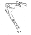
- Fig. 8
- eine Draufsicht von unten auf den erfindungsgemäßen Beschlag bei 60° geöffnetem Flügel;
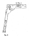
- Fig. 9
- eine Draufsicht von unten auf den erfindungsgemäßen Beschlag bei 100° geöffnetem Flügel.
- Fig. 1
- a fitting according to the invention in a perspective view;
- Fig. 2
- a side view of the fitting according to the invention;
- Fig. 3
- a perspective view of a slider;
- Fig. 4
- a plan view of a slider;
- Fig. 5
- a section through the slider according to the line IV - IV of
FIG. 4 ; - Fig. 6
- a plan view from below of the fitting according to the invention with the wing closed;
- Fig. 7
- a plan view from below of the fitting according to the invention at 15 ° open wing;
- Fig. 8
- a plan view from below of the fitting according to the invention at 60 ° open wing;
- Fig. 9
- a plan view from below of the fitting according to the invention at 100 ° open wing.
In den
Das Beschlagteil 5 kann mit einem Rahmen verschraubt werden. An dem Flügel ist ein Eckband 10 vorgesehen, mit dem der Flügel sich auf der ersten Lasche 6 abstützt.The fitting 5 can be bolted to a frame. On the wing, a
Ein Tragbolzen 15 steht von der ersten Lasche 6 ab. Auf diesem Tragbolzen 15 sitzt das Eckband 10. Der Tragbolzen 15 bildet eine Eckbandaufnahme. Die zweite Lasche 7 weist an ihrem freien Ende ebenfalls einen Bolzen 16 auf, der von unten in das Eckband 10 eingreift. Das Gewicht des Flügels wird über das Eckband 10 auf den Tragbolzen 15 übertragen. Dieser überträgt das Gewicht dann auf die erste Lasche 6. Die erste Lasche 6 liegt auf der zweiten Lasche 7 auf und überträgt somit die Last auf die zweite Lasche 7. Die Scherengeometrie wurde so gewählt, dass eine möglichst große Überlappung der ersten Lasche 6 und der zweiten Lasche 7 bei geöffnetem Flügel vorhanden ist. Somit wird ein entstehendes Biegemoment klein gehalten. Die zweite Lasche 7 muss eine größere Last aufnehmen als erste Lasche 6. Deshalb ist die zweite Lasche 7 dicker ausgebildet als erste Lasche 6.A
Aus der Darstellung der
Durch das Flügelgewicht, welches auf die erste Lasche 6 wirkt, ist die erste Lasche 6 bestrebt, über die zweite Lasche 7 abzukippen. Es entsteht also eine Kraft auf die erste Lasche 6. Diese Kraft ist bestrebt, das Gleitstück 25 aus der Führung 9 zu ziehen. Aufgrund der Schwerkraft des Flügels wird auf das Gleitstück 25 über die erste Lasche 6 außerdem eine Kraftkomponente in horizontaler Richtung ausgeübt.By the sash weight, which acts on the first tab 6, the first tab 6 endeavors to tip over the
In der
In der
In der
Der Schnittdarstellung der
In den
In der
Bei einer weiteren Öffnungsbewegung, die in der
In einer vollständigen Öffnungsstellung, die in der
Claims (17)
- Fitting (2) for a window, door or the like, having a fitting member (5) which has a guide (9), and having a first plate (6) which is connected to a sliding piece (25) which is guided in the guide (9), with the guide (9) having at least one lateral guide sliding face (42, 43), along which the sliding piece (25) slides when the plate (6) moves, characterised in that the at least one lateral guide sliding face (42, 43) and a sliding piece face (32, 33), which slides along the guide sliding face (42, 43) during a movement of the plate (6), conform to each other in such a manner that the sliding piece face (32, 33) abuts the guide sliding face (42, 43) at various locations during the movement along the guide sliding face (42, 43).
- Fitting according to claim 1, characterised in that the guide (9) has two guide sliding faces (42, 43) and the sliding piece (25) has two sliding piece faces (32, 33) which each conform to a guide sliding face (42, 43).
- Fitting according to claim 1 or claim 2, characterised in that the sliding piece (25) is connected to the plate (6) in a rotationally secure manner.
- Fitting according to any one of the preceding claims, characterised in that the guide (9) is constructed so as to be curved and/or is orientated obliquely relative to a longitudinal direction of the fitting member (5).
- Fitting according to any one of the preceding claims, characterised in that the guide (9) has an undercut and the sliding piece (25) has an upper portion (30), with which it engages behind the guide in the region of the undercut.
- Fitting according to any one of the preceding claims, characterised in that the sliding piece (25) is in the form of a sliding rivet.
- Fitting according to any one of the preceding claims, characterised in that the sliding rivet has, at the end thereof to be secured to the plate (6), an orientation aid (26) which is adapted to an orientation aid of the plate (6) .
- Fitting according to any one of the preceding claims, characterised in that the sliding rivet has an assembly aid (34), by means of which the sliding rivet can be orientated in a rivet tool.
- Fitting according to any one of the preceding claims 1 to 5, characterised in that the sliding piece (25) is connected to the plate (6) in a materially integral manner.
- Fitting according to claim 9, characterised in that the sliding piece (25) is pressed or punched from or formed on the plate (6).
- Fitting according to any one of the preceding claims, characterised in that there is provided a second plate (7) which is pivotably connected to the first plate (6) and the fitting member (5).
- Fitting according to any one of the preceding claims, characterised in that one plate (6, 7) is constructed so as to be thicker than the other.
- Fitting according to any one of the preceding claims, characterised in that the first plate (6) has a corner plate receptacle, in particular a carrier pin (15).
- Fitting according to any one of the preceding claims, characterised in that a downwardly directed load-receiving device (20) is provided.
- Fitting according to any one of the preceding claims 11 to 14, characterised in that the second plate (7) is in the form of a carrier plate and the fitting member (5) is in the form of a base plate which can be secured to a frame, with the base plate having at least a portion of the load-receiving device (20).
- Fitting according to any one of the preceding claims, characterised in that the base plate has a downwardly directed sleeve (21), in which a downwardly directed support pin (22) of the carrier plate is rotatably arranged.
- Window, door or the like, having a fixed frame and/or at least one leaf, comprising a fitting (2) according to any one of the preceding claims.
Priority Applications (6)
| Application Number | Priority Date | Filing Date | Title |
|---|---|---|---|
| AT06026862T ATE426078T1 (en) | 2006-12-23 | 2006-12-23 | FITTINGS FOR WINDOWS, DOORS OR THE LIKE. |
| SI200630278T SI1936085T1 (en) | 2006-12-23 | 2006-12-23 | Fitting for windows, doors or similar |
| ES06026862T ES2322288T3 (en) | 2006-12-23 | 2006-12-23 | HARDWARE FOR WINDOWS, DOORS OR SIMILAR. |
| DE502006003211T DE502006003211D1 (en) | 2006-12-23 | 2006-12-23 | Fitting for windows, doors or the like. |
| EP06026862A EP1936085B1 (en) | 2006-12-23 | 2006-12-23 | Fitting for windows, doors or similar |
| PL06026862T PL1936085T3 (en) | 2006-12-23 | 2006-12-23 | Fitting for windows, doors or similar |
Applications Claiming Priority (1)
| Application Number | Priority Date | Filing Date | Title |
|---|---|---|---|
| EP06026862A EP1936085B1 (en) | 2006-12-23 | 2006-12-23 | Fitting for windows, doors or similar |
Publications (2)
| Publication Number | Publication Date |
|---|---|
| EP1936085A1 EP1936085A1 (en) | 2008-06-25 |
| EP1936085B1 true EP1936085B1 (en) | 2009-03-18 |
Family
ID=37944878
Family Applications (1)
| Application Number | Title | Priority Date | Filing Date |
|---|---|---|---|
| EP06026862A Not-in-force EP1936085B1 (en) | 2006-12-23 | 2006-12-23 | Fitting for windows, doors or similar |
Country Status (6)
| Country | Link |
|---|---|
| EP (1) | EP1936085B1 (en) |
| AT (1) | ATE426078T1 (en) |
| DE (1) | DE502006003211D1 (en) |
| ES (1) | ES2322288T3 (en) |
| PL (1) | PL1936085T3 (en) |
| SI (1) | SI1936085T1 (en) |
Families Citing this family (1)
| Publication number | Priority date | Publication date | Assignee | Title |
|---|---|---|---|---|
| CN107288458A (en) * | 2017-07-07 | 2017-10-24 | 亚萨合莱国强(山东)五金科技有限公司 | Use in construction of door and window built-in hinge |
Family Cites Families (6)
| Publication number | Priority date | Publication date | Assignee | Title |
|---|---|---|---|---|
| DE3843680C2 (en) * | 1988-12-23 | 1996-05-15 | Bayerwald Fensterfabrik Altenb | Concealed fitting for swivel bearings of doors, windows or the like |
| ITBO20010049A1 (en) * | 2001-01-31 | 2002-07-31 | Gsg Int Spa | MANEUVERING GROUP FOR FIXED WINDOWS |
| DE10159687B4 (en) * | 2001-11-28 | 2010-03-11 | Roto Frank Ag | Ausstellvorrichtung for a rotary wing of a window, a door or the like |
| DE10228624B4 (en) * | 2002-06-26 | 2006-08-10 | Geze Gmbh | Fitting for a grand piano |
| ITTO20040437A1 (en) * | 2004-06-28 | 2004-09-28 | Savio Spa | HINGE DEVICE FOR WINDOWS |
| DE202006003177U1 (en) * | 2006-03-01 | 2006-04-20 | SCHÜCO International KG | Hardware for windows or doors |
-
2006
- 2006-12-23 AT AT06026862T patent/ATE426078T1/en active
- 2006-12-23 SI SI200630278T patent/SI1936085T1/en unknown
- 2006-12-23 DE DE502006003211T patent/DE502006003211D1/en active Active
- 2006-12-23 EP EP06026862A patent/EP1936085B1/en not_active Not-in-force
- 2006-12-23 PL PL06026862T patent/PL1936085T3/en unknown
- 2006-12-23 ES ES06026862T patent/ES2322288T3/en active Active
Also Published As
| Publication number | Publication date |
|---|---|
| ATE426078T1 (en) | 2009-04-15 |
| DE502006003211D1 (en) | 2009-04-30 |
| ES2322288T3 (en) | 2009-06-18 |
| EP1936085A1 (en) | 2008-06-25 |
| SI1936085T1 (en) | 2009-06-30 |
| PL1936085T3 (en) | 2009-08-31 |
Similar Documents
| Publication | Publication Date | Title |
|---|---|---|
| EP2673442B1 (en) | Furniture hinge | |
| EP1788178B1 (en) | Bearing for windows, doors or the like | |
| EP2085553B1 (en) | Fitting for a corner support | |
| EP2682545B1 (en) | Closure assembly for a sliding door or sliding window, and sliding door or sliding window | |
| EP1936086B1 (en) | Corner fitting for windows, doors or similar | |
| AT511249B1 (en) | SLIDING DOOR FOR A VEHICLE | |
| EP3175068B1 (en) | Fitting arrangement | |
| EP2546438B1 (en) | Fitting part intended for mobile assembly in a fitting groove comprising an undercut | |
| EP1411201B1 (en) | Fitting | |
| EP1788175B1 (en) | Flat links assembly for windows, doors or the like | |
| EP1790813B1 (en) | Corner support for windows, doors or the same | |
| DE202008004292U1 (en) | Fitting for a tilting and tilting movement of a wing of a building window or a building door | |
| EP3060736B1 (en) | Fitting for windows, doors or the like | |
| EP1936085B1 (en) | Fitting for windows, doors or similar | |
| EP1863990B1 (en) | Driving rod drive | |
| EP1746235B1 (en) | Fitting assembly | |
| EP2365176B1 (en) | Device for unlocking a window, flap or similar | |
| EP2233039B1 (en) | Drawer guide | |
| EP4041975B1 (en) | Opening device for a turn-tilt sash of a window or door | |
| EP1759081B1 (en) | Outward positioning device | |
| EP2754815A2 (en) | Tilt fitting for wing of a window or a door | |
| EP3348761A1 (en) | Device for attaching a door leaf to a door frame so that it can be pivoted | |
| EP2685040B1 (en) | Pretensioning component and working method for a window or a sliding window-door | |
| EP2045426B1 (en) | Mounting device of a pivot bearing of a window | |
| EP3339544B1 (en) | Tilt fitting for wing of a window or a door |
Legal Events
| Date | Code | Title | Description |
|---|---|---|---|
| PUAI | Public reference made under article 153(3) epc to a published international application that has entered the european phase |
Free format text: ORIGINAL CODE: 0009012 |
|
| AK | Designated contracting states |
Kind code of ref document: A1 Designated state(s): AT BE BG CH CY CZ DE DK EE ES FI FR GB GR HU IE IS IT LI LT LU LV MC NL PL PT RO SE SI SK TR |
|
| AX | Request for extension of the european patent |
Extension state: AL BA HR MK RS |
|
| 17P | Request for examination filed |
Effective date: 20080625 |
|
| GRAP | Despatch of communication of intention to grant a patent |
Free format text: ORIGINAL CODE: EPIDOSNIGR1 |
|
| GRAS | Grant fee paid |
Free format text: ORIGINAL CODE: EPIDOSNIGR3 |
|
| GRAA | (expected) grant |
Free format text: ORIGINAL CODE: 0009210 |
|
| AKX | Designation fees paid |
Designated state(s): AT BE BG CH CY CZ DE DK EE ES FI FR GB GR HU IE IS IT LI LT LU LV MC NL PL PT RO SE SI SK TR |
|
| AK | Designated contracting states |
Kind code of ref document: B1 Designated state(s): AT BE BG CH CY CZ DE DK EE ES FI FR GB GR HU IE IS IT LI LT LU LV MC NL PL PT RO SE SI SK TR |
|
| REG | Reference to a national code |
Ref country code: GB Ref legal event code: FG4D Free format text: NOT ENGLISH |
|
| REG | Reference to a national code |
Ref country code: CH Ref legal event code: EP |
|
| REG | Reference to a national code |
Ref country code: IE Ref legal event code: FG4D Free format text: LANGUAGE OF EP DOCUMENT: GERMAN |
|
| REF | Corresponds to: |
Ref document number: 502006003211 Country of ref document: DE Date of ref document: 20090430 Kind code of ref document: P |
|
| REG | Reference to a national code |
Ref country code: ES Ref legal event code: FG2A Ref document number: 2322288 Country of ref document: ES Kind code of ref document: T3 |
|
| PG25 | Lapsed in a contracting state [announced via postgrant information from national office to epo] |
Ref country code: NL Free format text: LAPSE BECAUSE OF FAILURE TO SUBMIT A TRANSLATION OF THE DESCRIPTION OR TO PAY THE FEE WITHIN THE PRESCRIBED TIME-LIMIT Effective date: 20090318 Ref country code: LT Free format text: LAPSE BECAUSE OF FAILURE TO SUBMIT A TRANSLATION OF THE DESCRIPTION OR TO PAY THE FEE WITHIN THE PRESCRIBED TIME-LIMIT Effective date: 20090318 Ref country code: FI Free format text: LAPSE BECAUSE OF FAILURE TO SUBMIT A TRANSLATION OF THE DESCRIPTION OR TO PAY THE FEE WITHIN THE PRESCRIBED TIME-LIMIT Effective date: 20090318 |
|
| PG25 | Lapsed in a contracting state [announced via postgrant information from national office to epo] |
Ref country code: LV Free format text: LAPSE BECAUSE OF FAILURE TO SUBMIT A TRANSLATION OF THE DESCRIPTION OR TO PAY THE FEE WITHIN THE PRESCRIBED TIME-LIMIT Effective date: 20090318 Ref country code: SE Free format text: LAPSE BECAUSE OF FAILURE TO SUBMIT A TRANSLATION OF THE DESCRIPTION OR TO PAY THE FEE WITHIN THE PRESCRIBED TIME-LIMIT Effective date: 20090618 |
|
| REG | Reference to a national code |
Ref country code: PL Ref legal event code: T3 |
|
| NLV1 | Nl: lapsed or annulled due to failure to fulfill the requirements of art. 29p and 29m of the patents act | ||
| REG | Reference to a national code |
Ref country code: IE Ref legal event code: FD4D |
|
| REG | Reference to a national code |
Ref country code: HU Ref legal event code: AG4A Ref document number: E005856 Country of ref document: HU |
|
| PG25 | Lapsed in a contracting state [announced via postgrant information from national office to epo] |
Ref country code: PT Free format text: LAPSE BECAUSE OF FAILURE TO SUBMIT A TRANSLATION OF THE DESCRIPTION OR TO PAY THE FEE WITHIN THE PRESCRIBED TIME-LIMIT Effective date: 20090827 Ref country code: IE Free format text: LAPSE BECAUSE OF FAILURE TO SUBMIT A TRANSLATION OF THE DESCRIPTION OR TO PAY THE FEE WITHIN THE PRESCRIBED TIME-LIMIT Effective date: 20090318 Ref country code: EE Free format text: LAPSE BECAUSE OF FAILURE TO SUBMIT A TRANSLATION OF THE DESCRIPTION OR TO PAY THE FEE WITHIN THE PRESCRIBED TIME-LIMIT Effective date: 20090318 |
|
| PG25 | Lapsed in a contracting state [announced via postgrant information from national office to epo] |
Ref country code: IS Free format text: LAPSE BECAUSE OF FAILURE TO SUBMIT A TRANSLATION OF THE DESCRIPTION OR TO PAY THE FEE WITHIN THE PRESCRIBED TIME-LIMIT Effective date: 20090718 Ref country code: RO Free format text: LAPSE BECAUSE OF FAILURE TO SUBMIT A TRANSLATION OF THE DESCRIPTION OR TO PAY THE FEE WITHIN THE PRESCRIBED TIME-LIMIT Effective date: 20090318 Ref country code: SK Free format text: LAPSE BECAUSE OF FAILURE TO SUBMIT A TRANSLATION OF THE DESCRIPTION OR TO PAY THE FEE WITHIN THE PRESCRIBED TIME-LIMIT Effective date: 20090318 |
|
| PLBE | No opposition filed within time limit |
Free format text: ORIGINAL CODE: 0009261 |
|
| STAA | Information on the status of an ep patent application or granted ep patent |
Free format text: STATUS: NO OPPOSITION FILED WITHIN TIME LIMIT |
|
| PG25 | Lapsed in a contracting state [announced via postgrant information from national office to epo] |
Ref country code: DK Free format text: LAPSE BECAUSE OF FAILURE TO SUBMIT A TRANSLATION OF THE DESCRIPTION OR TO PAY THE FEE WITHIN THE PRESCRIBED TIME-LIMIT Effective date: 20090318 Ref country code: BG Free format text: LAPSE BECAUSE OF FAILURE TO SUBMIT A TRANSLATION OF THE DESCRIPTION OR TO PAY THE FEE WITHIN THE PRESCRIBED TIME-LIMIT Effective date: 20090618 |
|
| 26N | No opposition filed |
Effective date: 20091221 |
|
| PG25 | Lapsed in a contracting state [announced via postgrant information from national office to epo] |
Ref country code: MC Free format text: LAPSE BECAUSE OF NON-PAYMENT OF DUE FEES Effective date: 20100701 |
|
| PG25 | Lapsed in a contracting state [announced via postgrant information from national office to epo] |
Ref country code: GR Free format text: LAPSE BECAUSE OF FAILURE TO SUBMIT A TRANSLATION OF THE DESCRIPTION OR TO PAY THE FEE WITHIN THE PRESCRIBED TIME-LIMIT Effective date: 20090619 |
|
| PG25 | Lapsed in a contracting state [announced via postgrant information from national office to epo] |
Ref country code: LU Free format text: LAPSE BECAUSE OF NON-PAYMENT OF DUE FEES Effective date: 20091223 |
|
| PGRI | Patent reinstated in contracting state [announced from national office to epo] |
Ref country code: IT Effective date: 20110501 |
|
| PG25 | Lapsed in a contracting state [announced via postgrant information from national office to epo] |
Ref country code: TR Free format text: LAPSE BECAUSE OF FAILURE TO SUBMIT A TRANSLATION OF THE DESCRIPTION OR TO PAY THE FEE WITHIN THE PRESCRIBED TIME-LIMIT Effective date: 20090318 |
|
| PG25 | Lapsed in a contracting state [announced via postgrant information from national office to epo] |
Ref country code: CY Free format text: LAPSE BECAUSE OF FAILURE TO SUBMIT A TRANSLATION OF THE DESCRIPTION OR TO PAY THE FEE WITHIN THE PRESCRIBED TIME-LIMIT Effective date: 20090318 |
|
| REG | Reference to a national code |
Ref country code: FR Ref legal event code: PLFP Year of fee payment: 10 |
|
| REG | Reference to a national code |
Ref country code: FR Ref legal event code: PLFP Year of fee payment: 11 |
|
| PGFP | Annual fee paid to national office [announced via postgrant information from national office to epo] |
Ref country code: HU Payment date: 20161213 Year of fee payment: 11 Ref country code: CZ Payment date: 20161213 Year of fee payment: 11 |
|
| PGFP | Annual fee paid to national office [announced via postgrant information from national office to epo] |
Ref country code: BE Payment date: 20161221 Year of fee payment: 11 Ref country code: PL Payment date: 20161125 Year of fee payment: 11 Ref country code: SI Payment date: 20161214 Year of fee payment: 11 |
|
| REG | Reference to a national code |
Ref country code: FR Ref legal event code: PLFP Year of fee payment: 12 |
|
| PG25 | Lapsed in a contracting state [announced via postgrant information from national office to epo] |
Ref country code: CZ Free format text: LAPSE BECAUSE OF NON-PAYMENT OF DUE FEES Effective date: 20171223 |
|
| REG | Reference to a national code |
Ref country code: SI Ref legal event code: KO00 Effective date: 20180806 |
|
| REG | Reference to a national code |
Ref country code: BE Ref legal event code: MM Effective date: 20171231 |
|
| PG25 | Lapsed in a contracting state [announced via postgrant information from national office to epo] |
Ref country code: HU Free format text: LAPSE BECAUSE OF NON-PAYMENT OF DUE FEES Effective date: 20171224 |
|
| PG25 | Lapsed in a contracting state [announced via postgrant information from national office to epo] |
Ref country code: SI Free format text: LAPSE BECAUSE OF NON-PAYMENT OF DUE FEES Effective date: 20171224 Ref country code: BE Free format text: LAPSE BECAUSE OF NON-PAYMENT OF DUE FEES Effective date: 20171231 |
|
| PGFP | Annual fee paid to national office [announced via postgrant information from national office to epo] |
Ref country code: IT Payment date: 20181018 Year of fee payment: 15 Ref country code: FR Payment date: 20181218 Year of fee payment: 13 |
|
| PG25 | Lapsed in a contracting state [announced via postgrant information from national office to epo] |
Ref country code: PL Free format text: LAPSE BECAUSE OF NON-PAYMENT OF DUE FEES Effective date: 20171223 |
|
| PGFP | Annual fee paid to national office [announced via postgrant information from national office to epo] |
Ref country code: AT Payment date: 20191213 Year of fee payment: 14 |
|
| PGFP | Annual fee paid to national office [announced via postgrant information from national office to epo] |
Ref country code: DE Payment date: 20191221 Year of fee payment: 14 Ref country code: ES Payment date: 20200122 Year of fee payment: 14 Ref country code: GB Payment date: 20191220 Year of fee payment: 14 |
|
| REG | Reference to a national code |
Ref country code: CH Ref legal event code: PL |
|
| PG25 | Lapsed in a contracting state [announced via postgrant information from national office to epo] |
Ref country code: FR Free format text: LAPSE BECAUSE OF NON-PAYMENT OF DUE FEES Effective date: 20191231 |
|
| PG25 | Lapsed in a contracting state [announced via postgrant information from national office to epo] |
Ref country code: LI Free format text: LAPSE BECAUSE OF NON-PAYMENT OF DUE FEES Effective date: 20191231 Ref country code: CH Free format text: LAPSE BECAUSE OF NON-PAYMENT OF DUE FEES Effective date: 20191231 |
|
| REG | Reference to a national code |
Ref country code: DE Ref legal event code: R119 Ref document number: 502006003211 Country of ref document: DE |
|
| REG | Reference to a national code |
Ref country code: AT Ref legal event code: MM01 Ref document number: 426078 Country of ref document: AT Kind code of ref document: T Effective date: 20201223 |
|
| GBPC | Gb: european patent ceased through non-payment of renewal fee |
Effective date: 20201223 |
|
| PG25 | Lapsed in a contracting state [announced via postgrant information from national office to epo] |
Ref country code: AT Free format text: LAPSE BECAUSE OF NON-PAYMENT OF DUE FEES Effective date: 20201223 |
|
| PG25 | Lapsed in a contracting state [announced via postgrant information from national office to epo] |
Ref country code: GB Free format text: LAPSE BECAUSE OF NON-PAYMENT OF DUE FEES Effective date: 20201223 Ref country code: DE Free format text: LAPSE BECAUSE OF NON-PAYMENT OF DUE FEES Effective date: 20210701 |
|
| REG | Reference to a national code |
Ref country code: ES Ref legal event code: FD2A Effective date: 20220222 |
|
| PG25 | Lapsed in a contracting state [announced via postgrant information from national office to epo] |
Ref country code: ES Free format text: LAPSE BECAUSE OF NON-PAYMENT OF DUE FEES Effective date: 20201224 |
|
| PG25 | Lapsed in a contracting state [announced via postgrant information from national office to epo] |
Ref country code: IT Free format text: LAPSE BECAUSE OF NON-PAYMENT OF DUE FEES Effective date: 20201223 |