EP2233039B1 - Drawer guide - Google Patents
Drawer guide Download PDFInfo
- Publication number
- EP2233039B1 EP2233039B1 EP10157041.4A EP10157041A EP2233039B1 EP 2233039 B1 EP2233039 B1 EP 2233039B1 EP 10157041 A EP10157041 A EP 10157041A EP 2233039 B1 EP2233039 B1 EP 2233039B1
- Authority
- EP
- European Patent Office
- Prior art keywords
- drawer
- catch
- lift
- designed
- clamping surface
- Prior art date
- Legal status (The legal status is an assumption and is not a legal conclusion. Google has not performed a legal analysis and makes no representation as to the accuracy of the status listed.)
- Active
Links
Images


Classifications
-
- A—HUMAN NECESSITIES
- A47—FURNITURE; DOMESTIC ARTICLES OR APPLIANCES; COFFEE MILLS; SPICE MILLS; SUCTION CLEANERS IN GENERAL
- A47B—TABLES; DESKS; OFFICE FURNITURE; CABINETS; DRAWERS; GENERAL DETAILS OF FURNITURE
- A47B88/00—Drawers for tables, cabinets or like furniture; Guides for drawers
- A47B88/40—Sliding drawers; Slides or guides therefor
- A47B88/423—Fastening devices for slides or guides
- A47B88/427—Fastening devices for slides or guides at drawer side
Definitions
- the present invention relates to a drawer slide according to the preamble of claim 1.
- Such a solution is for example from the DE 41 14 708 A1 known.
- Object of the present invention is therefore to provide a drawer guide, which provides a simple and secure Abhebesch, especially for drawers, which are positioned directly above the bottom of a furniture body.
- the Abhebetician is designed as a clamping surface with two vertical standing on the clamping surface dowels, wherein the dowels are fixed in a bore of the drawer and the fixed to the running rail driver is pressed by the clamping surface to the drawer frame, wherein the dowels at the ends of a Clamping web trained clamping surface are positioned.
- the lift-off safety device can be adapted to all standard grid dimensions in the furniture industry. Furthermore, the bore diameter in the drawer frame for the anchor corresponds to that for the driving pin, which greatly simplifies the production. In addition, can be carried out in a very limited space by the solution according to the invention a mounting of the lift-off. Another advantage is the simple tool-free feasible installation of the lift-off on the drawer frame. Furthermore, this makes it possible that the driver is pressed in the mounted state of a clamping surface to the drawer frame, which right and left of the driver is fixed by a dowel reliable to the drawer frame.
- the clamping surface on the side from which the dowels protrude a recess for receiving a driver.
- a height adjustment effected by adjusting the driving pin formed as a height adjustment element and thus does not project downwards.
- this recess is formed with at least one joining element for positioning the driver. Thereby, the driver is securely positioned in a predetermined position on the clamping surface.
- the or the dowels are designed as releasable expansion dowel, in particular as Exzentermuffe with a rotatable eccentric in the eccentric eccentric.
- the sleeves are spread and can be easily released by turning back the eccentric lever.
- the sides of the eccentric sleeve only press in the longitudinal direction of the drawer frame.
- a drawer slide for a plug-in drawer 1 disposed in a furniture body comprises, as in FIG. 1 shown, a running rail 4, which is releasably coupled to a drawer frame 2 via a fixed to the running rail 4 driver 6.
- the running rail 4 extends along the inside of the drawer 2, wherein the driver 6 extends to the lower end edge 3 of the drawer 2.
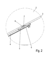
- This driver 6 will, as in FIG. 2 and 3 can be seen, with the help of a lift-off 5, which is attached to the lower end edge 3 of the drawer 2, pressed against this end face 3 of the drawer 2.
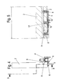
- the driver 6 consists of how FIG. 5 shows, from a surface element 10 and a vertically projecting from the surface element 10 driving pin 11. This drive pin 11 extends when placing the drawer in a bore 15 in the front edge 3 of the drawer frame 2.
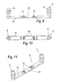
- a first preferred embodiment of the lift-off 5 is in the FIGS. 6 to 8 shown.
- the anti-lift device 5 has a clamping surface 12 with at least one, in the embodiment shown here with two, perpendicular to the clamping surface 12 dowels 8. These dowels 8 are in holes 16 (shown in FIG FIG. 12 ) of the drawer 2, in particular the lower end edge 3 of the drawer 2, fixed, preferably by pressing.
- the clamping surface 12 of the anti-lift device 5 is preferably designed in the form of a clamping web, wherein the dowels 8 are respectively positioned at the ends of the clamping web 12.
- the clamping surface 12 is formed on the side from which the dowels 8 project, with a recess 13.
- the width of this recess 13 is preferably slightly larger than the width of a surface element 10, so that when a height adjustment, the surface element 10 is not jammed in the recess 13, but rests flush and does not project down.
- the lift-off 5 are in the recess 13 of the clamping surface 12 at least one joining element 14, in the embodiment shown here, two joining elements 14, provided for positioning the driver 6.
- These joining elements 14 are preferably formed as nipples, which engage in the mounted state in a corresponding recess 17 on a side facing away from the driving pin 11 side of the surface element 10 of the driver.
- the driving pin 11 is preferably formed as a height adjustment element for height adjustment of the drawer 2 with respect to the running rail 4.
- a thumbwheel 7 is arranged on the driving pin 11, with the manual exact height positioning of the drawer 1 relative to the running rail 4 is feasible.
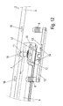
- the dowels 8 are preferably designed on their lateral surface such that a simple pressing the dowel 8 is ensured in the corresponding bore 16 of the drawer 2, for example in the form of a mushroom dowel.
- the dowels 8 are designed as releasable expansion dowel.
- eccentric lever 18 are provided, which, as in FIG. 15 shown protruding from a lever piece 20 and a vertically projecting from the lever piece eccentric piece 19.
- the eccentric 19 is arranged inside in a cavity of the expansion dowel 8, so that the expansion dowel 8 are spread open by a rotational movement of the eccentric lever 18 and thereby fix the lift-off 5 in the holes 16 of the drawer 2.
- the lift-off 5 to solve by pivoting back the eccentric lever 18 again.
Description
Die vorliegende Erfindung betrifft eine Schubkastenführung gemäß dem Oberbegriff des Anspruchs 1.The present invention relates to a drawer slide according to the preamble of
Bei gattungsgemäßen Schubkastenführungen wird ein in einem Möbelkorpus eingebauter Schubkasten über einen Schnäpper mit einer Laufschiene einer Auszugsführung verbunden, wobei der Schnäpper mit einer Klinke in die Laufschiene einhakt und so ein Abheben des Schubkastens aus der Laufschiene verhindert. In einer anderen Führungsvariante wird der Schubkasten lediglich von oben auf einen Mitnehmerbolzen gedrückt, wobei der Mitnehmerbolzen fest mit der Laufschiene verbunden ist. Wird dieser Schubkasten nun manuell aus einem Möbelkorpus ausgezogen, besteht die Gefahr, dass der Schubkasten von der Laufschiene abgehoben wird. Dieses Problem besteht insbesondere bei Schubkästen, die relativ weit unten bzw. unmittelbar über dem Boden des Möbelkorpus im Möbelkorpus eingebaut sind, da beim Herausziehen des Schubkastens durch einen Benutzer eine von diesem auf den Schubkasten ausgeübte Kraft nicht nur in horizontaler Verfahrrichtung der Schubkastenführung, sondern auch in vertikaler Richtung nach oben ausübt wird. Ein Abheben des Schubkastens von der Laufschiene wird bei dieser Aufsatzvariante derzeit dadurch verhindert, dass der Mitnehmer bzw. ein Mitnehmerblech des Mitnehmers mit der unteren Stirnkante der Schubkastenzarge verschraubt wird.In generic drawer guides a built-in furniture cabinet drawer is connected via a catch with a running rail a pullout guide, the catch hooks with a pawl in the track and prevents lifting the drawer from the track. In another variant of the guide, the drawer is pressed only from above on a driving pin, wherein the driving pin is fixedly connected to the running rail. If this drawer is now manually pulled out of a furniture body, there is a risk that the drawer is lifted off the track. This problem is particularly in the case of drawers which are installed relatively far below or directly above the bottom of the furniture body in the furniture body, as pulling out of the drawer by a user exerted by this on the drawer force not only in the horizontal direction of the drawer slide, but also is exerted in a vertical upward direction. A lifting of the drawer of the running rail is currently prevented in this essay variant in that the driver or a driver plate of the driver is bolted to the lower end edge of the drawer frame.
Eine derartige Lösung ist beispielsweise aus der
Problematisch ist bei dieser Befestigung, dass insbesondere bei Schubkästen, die in einen Möbelkorpus unmittelbar über den Boden des Möbelkorpus angeordnet sind, der zum Verschrauben notwendige Platz nicht gegeben ist und daher eine Sicherung nicht mehr möglich ist.The problem with this attachment, that in particular with drawers which are arranged in a furniture carcass directly above the bottom of the furniture body, the necessary space for screwing is not given and therefore a backup is no longer possible.
Aufgabe der vorliegenden Erfindung ist es daher, eine Schubkastenführung bereitzustellen, die eine einfache und sichere Abhebesicherung bereitstellt, insbesondere für Schubkästen, welche unmittelbar über dem Boden eines Möbelkorpus positioniert sind.Object of the present invention is therefore to provide a drawer guide, which provides a simple and secure Abhebesicherung, especially for drawers, which are positioned directly above the bottom of a furniture body.
Diese Aufgabe wird durch eine Schubkastenführung mit den Merkmalen des Anspruchs 1 gelöst.This object is achieved by a drawer guide with the features of
Erfindungsgemäß ist die Abhebesicherung als Klemmfläche mit zwei senkrecht auf der Klemmfläche stehenden Dübeln ausgebildet, wobei die Dübel in einer Bohrung der Schubkastenzarge fixierbar sind und der an der Laufschiene fixierte Mitnehmer durch die Klemmfläche an die Schubkastenzarge andrückbar ist, wobei die Dübel an den Enden einer als Klemmsteg ausgebildeten Klemmfläche positioniert sind.According to the Abhebesicherung is designed as a clamping surface with two vertical standing on the clamping surface dowels, wherein the dowels are fixed in a bore of the drawer and the fixed to the running rail driver is pressed by the clamping surface to the drawer frame, wherein the dowels at the ends of a Clamping web trained clamping surface are positioned.
Durch das Einpressen dieser Abhebesicherung in die Schubkastenzarge wird der Schubkasten auf der Laufschiene in einfacher und wirkungsvoller Weise gesichert. Auch der zusätzliche Montageaufwand ist bei dieser Lösung sehr gering, da in der Schubkastenzarge lediglich eine oder mehrere zusätzliche Bohrungen zur Unterbringung der Dübel eingebracht werden müssen, in die die Dübel der Abhebesicherung eingreifen. Die Abhebesicherung ist adaptierbar für alle im Möbelbereich gängigen Rastermaße. Weiterhin entspricht der Bohrungsdurchmesser in der Schubkastenzarge für den Dübel demjenigen für den Mitnehmerbolzen, welches die Fertigung stark vereinfacht. Außerdem kann durch die erfindungsgemäße Lösung eine Montage der Abhebesicherung auch bei sehr eingeschränktem Bauraum durchgeführt werden. Ein weiterer Vorteil ist die einfache werkzeuglose durchführbare Montage der Abhebesicherung an der Schubkastenzarge. Desweiteren ist dadurch ermöglicht, dass der Mitnehmer im montierten Zustand von einer Klemmfläche an die Schubkastenzarge angedrückt wird, welche rechts und links des Mitnehmer durch einen Dübel zuverlässig an der Schubkastenzarge fixiert ist.By pressing this anti-lifting device in the drawer frame of the drawer is secured to the track in a simple and effective manner. Also, the additional installation effort is very low in this solution, since only one or more additional holes for accommodating the dowels must be introduced into the drawer frame, in which engage the dowels of the lift-off. The lift-off safety device can be adapted to all standard grid dimensions in the furniture industry. Furthermore, the bore diameter in the drawer frame for the anchor corresponds to that for the driving pin, which greatly simplifies the production. In addition, can be carried out in a very limited space by the solution according to the invention a mounting of the lift-off. Another advantage is the simple tool-free feasible installation of the lift-off on the drawer frame. Furthermore, this makes it possible that the driver is pressed in the mounted state of a clamping surface to the drawer frame, which right and left of the driver is fixed by a dowel reliable to the drawer frame.
Vorteilhafte Weiterbildungen der Erfindung sind Gegenstand der Unteransprüche.Advantageous developments of the invention are the subject of the dependent claims.
Bevorzugt weist die Klemmfläche auf der Seite, aus der die Dübel hervorstehen, eine Aussparung zur Aufnahme eines Mitnehmers auf. Dadurch wird wirksam verhindert, dass die Klemmfläche infolge einer Höhenverstellung, bewirkt durch verstellen des als Höhenverstellelement ausgebildeten Mitnehmerbolzens, nach unten bewegt wird und somit nicht nach unten übersteht.Preferably, the clamping surface on the side from which the dowels protrude, a recess for receiving a driver. As a result, it is effectively prevented that the clamping surface is moved downwards due to a height adjustment, effected by adjusting the driving pin formed as a height adjustment element and thus does not project downwards.
In einer bevorzugten Ausführungsform ist diese Aussparung mit mindestens einem Fügeelement zur Positionierung des Mitnehmers ausgebildet. Dadurch ist der Mitnehmer sicher in einer vorbestimmten Position an der Klemmfläche positionierbar.In a preferred embodiment, this recess is formed with at least one joining element for positioning the driver. Thereby, the driver is securely positioned in a predetermined position on the clamping surface.
Gemäß einer weiteren bevorzugten Ausführungsvariante ist der oder sind die Dübel als lösbare Spreizdübel ausgebildet, insbesondere als Exzentermuffe mit einem in der Exzentermuffe verdrehbaren Exzenterhebel. Durch Drehen dieses Exzenterhebels werden die Muffen gespreizt und können durch Zurückdrehen des Exzenterhebels auch leicht wieder gelöst werden. Vorzugsweise drücken die Seiten der Exzentermuffe nur in Längsrichtung der Schubkastenzarge. Dadurch können auch dünne Schubkastenzargen mit der Abhebesicherung bestückt werden, da die Krafteinleitung nicht in die dünnen Wände, sondern in das Vollmaterial erfolgt.According to a further preferred embodiment, the or the dowels are designed as releasable expansion dowel, in particular as Exzentermuffe with a rotatable eccentric in the eccentric eccentric. By turning this eccentric lever, the sleeves are spread and can be easily released by turning back the eccentric lever. Preferably, the sides of the eccentric sleeve only press in the longitudinal direction of the drawer frame. As a result, even thin drawer frames can be equipped with the lift-off, since the force is not introduced into the thin walls, but in the solid material.
Im Folgenden werden bevorzugte Ausführungsbeispiele der Erfindung anhand der beiliegenden Zeichnungen näher erläutert. Es zeigen:
- Fig. 1
- eine schematische perspektivische Darstellung einer an einem Schubkasten angeordneten Schubkastenführung,
- Fig. 2
- eine Detailansicht der Abhebesicherung der
Figur 1 - Fig. 3
- eine schematische Ansicht der an der Schubkastenzarge angeordneten Abhebesicherung von unten,
- Fig. 4
- eine schematische Frontansicht der Schubkastenführung,
- Fig. 5
- eine Schnittansicht entlang der in
Figur 4 - Fig. 6-8
- unterschiedliche Ansichten einer Ausführungsvariante einer Abhebesicherung,
- Fig. 9 bis 11
- eine weitere Ausführungsvariante der Abhebesicherung,
- Fig. 12
- eine schematische perspektivische Ansicht der Abhebesicherung vor der Montage an einer Schubkastenzarge und
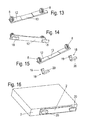
- Fig. 13 bis 16
- verschiedene schematische Ansichten einer weiteren Ausführungsvariante der Abhebesicherung.
- Fig. 1
- a schematic perspective view of a arranged on a drawer drawer slide,
- Fig. 2
- a detailed view of the lift-off of the
FIG. 1 . - Fig. 3
- a schematic view of the arranged on the drawer frame lift-off from below,
- Fig. 4
- a schematic front view of the drawer guide,
- Fig. 5
- a sectional view along the in
FIG. 4 with "B" designated cutting line, - Fig. 6-8
- different views of a variant of a lift-off,
- Fig. 9 to 11
- Another embodiment of the lift-off protection,
- Fig. 12
- a schematic perspective view of the anti-lifting device prior to assembly to a drawer frame and
- Fig. 13 to 16
- different schematic views of another embodiment of the lift-off.
Eine Schubkastenführung für einen in einem Möbelkorpus angeordneten aufsteckmontierten Schubkasten 1 umfasst, wie in
Dieser Mitnehmer 6 wird, wie in
Eine erste bevorzugte Ausführungsvariante der Abhebesicherung 5 ist in den
Die Klemmfläche 12 der Abhebesicherung 5 ist bevorzugt in Gestalt eines Klemmstegs ausgebildet, wobei die Dübel 8 jeweils an den Enden des Klemmstegs 12 positioniert sind.The clamping
Zur Aufnahme des Mitnehmers 6 ist die Klemmfläche 12 auf der Seite, aus der die Dübel 8 hervorstehen, mit einer Aussparung 13 ausgebildet. Die Breite dieser Aussparung 13 ist dabei bevorzugt etwas größer als die Breite eines Flächenelements 10, damit sich bei einer Höhenverstellung das Flächenelement 10 nicht in der Aussparung 13 verklemmt, sondern sich bündig anlegt und nicht nach unten übersteht.For receiving the
Bei der in den
Wie in
Die Dübel 8 sind auf Ihrer Mantelfläche bevorzugt derart gestaltet, dass ein einfaches Eindrücken der Dübel 8 in die entsprechende Bohrung 16 der Schubkastenzarge 2 gewährleistet ist, beispielsweise in Gestalt eines Pilzdübels. In einer besonderen Ausführungsvariante, gezeigt in den
- Schubkastendrawer
- 11
- Schubkastenzargedrawer
- 22
- Untere StirnkanteLower front edge
- 33
- Laufschienerunner
- 44
- Abhebesicherunglift-off
- 55
- Mitnehmertakeaway
- 66
- Rändelradknurl
- 77
- Dübeldowel
- 88th
- Aussparungrecess
- 99
- Flächenelementsurface element
- 1010
- Mitnehmerbolzendriving pins
- 1111
- Klemmflächeclamping surface
- 1212
- Aussparungrecess
- 1313
- Fügeelementjoining element
- 1414
- Bohrungdrilling
- 1515
- Bohrungendrilling
- 1616
- Aussparungrecess
- 1717
- ExzenterhebelCam
- 1818
- Exzenterstückeccentric
- 1919
- Hebelstücklever piece
- 2020
Claims (8)
- Drawer guide for a push-on mounted drawer (1) in a furniture carcass, comprising- a running rail (4) which is releasably coupled to a drawer frame (2) via a catch (6) secured to the running rail (4),- a lift-off protection device (5) locating the catch (6) on the drawer frame (2), wherein- the lift-off protection device (5) is designed as a clamping surface (12) with at least one dowel (8) standing upright on the clamping surface (12),- wherein the dowel (8) can be located in a bore (16) of the drawer frame (2), and- the catch (6) secured to the running rail (4) can be pushed against the drawer frame (2) by the clamping surface (12),
characterised in that- the lift-off protection device (5) comprises two dowels (8) standing upright on the clamping surface (12), each of which can be located in a bore (16) of the drawer frame (2), the clamping surface (12) being designed as a clamping web and the dowels (8) being positioned at the ends of the clamping web (12). - Drawer guide according to claim 1, characterised in that the clamping surface (12) has a recess (13) for the accommodation of the catch (6) on the side from which the dowels (8) project.
- Drawer guide according to any of the preceding claims, characterised in that the catch (6) consists of a surface element (10) secured to the running rail (4) and a catch pin (11) projecting at right angles from this surface element (10).
- Drawer guide according to claim 3, characterised in that the catch pin (11) is designed as a vertical adjusting element for the vertical adjustment of the drawer frame (2) relative to the running rail (4).
- Drawer guide according to claim 2, characterised in that the recess (13) comprises at least one joining element (14) for positioning the catch (6).
- Drawer guide according to claim 5, characterised in that the at least one joining element (14) is designed as a nipple which in the assembled state engages with a corresponding recess (17) on a side of the surface element (10) of the catch (6) which is remote from the catch pin (6).
- Drawer guide according to any of the preceding claims, characterised in that the at least one dowel (8) is designed as a releasable expansion plug.
- Drawer guide according to claim 7, characterised in that the releasable expansion plug is designed as an eccentric sleeve with an eccentric lever (20) capable of rotary adjustment in the eccentric sleeve.
Applications Claiming Priority (1)
| Application Number | Priority Date | Filing Date | Title |
|---|---|---|---|
| DE202009002002U DE202009002002U1 (en) | 2009-03-27 | 2009-03-27 | Drawer runner |
Publications (3)
| Publication Number | Publication Date |
|---|---|
| EP2233039A2 EP2233039A2 (en) | 2010-09-29 |
| EP2233039A3 EP2233039A3 (en) | 2011-05-04 |
| EP2233039B1 true EP2233039B1 (en) | 2013-05-08 |
Family
ID=42288636
Family Applications (1)
| Application Number | Title | Priority Date | Filing Date |
|---|---|---|---|
| EP10157041.4A Active EP2233039B1 (en) | 2009-03-27 | 2010-03-19 | Drawer guide |
Country Status (3)
| Country | Link |
|---|---|
| EP (1) | EP2233039B1 (en) |
| DE (1) | DE202009002002U1 (en) |
| ES (1) | ES2417318T3 (en) |
Families Citing this family (3)
| Publication number | Priority date | Publication date | Assignee | Title |
|---|---|---|---|---|
| DE102010036468A1 (en) * | 2010-07-16 | 2012-01-19 | Paul Hettich Gmbh & Co. Kg | Opening and / or closing device and method for mounting an opening and / or closing device |
| DE102011052564A1 (en) * | 2011-05-17 | 2012-11-22 | Paul Hettich Gmbh & Co. Kg | Movable furniture part and furniture |
| DE102019102221A1 (en) | 2019-01-29 | 2020-07-30 | Paul Hettich Gmbh & Co. Kg | Device for fixing a drawer and furniture |
Family Cites Families (8)
| Publication number | Priority date | Publication date | Assignee | Title |
|---|---|---|---|---|
| AT399264B (en) * | 1991-12-11 | 1995-04-25 | Blum Gmbh Julius | Withdrawal guide (runner) for drawers |
| ES2087524T3 (en) * | 1991-02-12 | 1996-07-16 | Blum Gmbh Julius | TELESCOPIC GUIDE FOR DRAWERS. |
| DE4114708C2 (en) * | 1991-05-06 | 2000-11-30 | Lautenschlaeger Mepla Werke | Fastening device for rails of drawer pull-out guides |
| AT400659B (en) * | 1992-08-17 | 1996-02-26 | Blum Gmbh Julius | Drawer |
| AT405009B (en) * | 1996-02-05 | 1999-04-26 | Blum Gmbh Julius | Runner (withdrawal fitting) for drawers |
| AT411005B (en) * | 1996-07-09 | 2003-09-25 | Alfit Ag | DRAWER GUIDE |
| AT410164B (en) * | 1996-08-20 | 2003-02-25 | Alfit Ag | DRAWER GUIDE |
| JP4139923B2 (en) * | 1997-05-13 | 2008-08-27 | ジュリウス ブルム ゲゼルシャフト エム.ビー.エイチ. | Furniture bracket |
-
2009
- 2009-03-27 DE DE202009002002U patent/DE202009002002U1/en not_active Expired - Lifetime
-
2010
- 2010-03-19 ES ES10157041T patent/ES2417318T3/en active Active
- 2010-03-19 EP EP10157041.4A patent/EP2233039B1/en active Active
Also Published As
| Publication number | Publication date |
|---|---|
| EP2233039A3 (en) | 2011-05-04 |
| EP2233039A2 (en) | 2010-09-29 |
| ES2417318T3 (en) | 2013-08-07 |
| DE202009002002U1 (en) | 2010-08-12 |
Similar Documents
| Publication | Publication Date | Title |
|---|---|---|
| AT509416B1 (en) | EXTRACTION GUIDE FOR A DRAWER | |
| EP2851497B1 (en) | Adjustable mounting device for a sliding element and sliding device | |
| EP2873792B1 (en) | Hinges | |
| EP1550385A2 (en) | Device for adjusting the height of a drawer | |
| DE102009025890A1 (en) | Device for attaching a front panel to a side frame of a movable furniture part of a piece of furniture, drawer and furniture | |
| WO2011151052A1 (en) | Connecting device and drawer having a connecting device | |
| WO2018033221A1 (en) | Furniture hinge | |
| AT398516B (en) | DRAWER EXTENSION | |
| EP2233039B1 (en) | Drawer guide | |
| DE102005028573B4 (en) | Fastening arrangement for furniture parts, in particular table furniture parts | |
| AT520765B1 (en) | Drawer side wall with a cover profile | |
| DE102014104135B4 (en) | Pull-out guide for a drawer | |
| EP3859105A1 (en) | Locking cylinder | |
| EP1794053B1 (en) | Device for fixing an object to a rail | |
| EP3773074B1 (en) | Drawer system with pull-out rail onto which different drawers can be installed | |
| DE202009016669U1 (en) | Furniture, furniture part and device for connecting a front component of a furniture part | |
| EP4105432A1 (en) | Automatic seal with a guiding means for guiding a push rod and method for positioning the guiding means in a housing of the seal | |
| DE202010014948U1 (en) | Device for driving a movable furniture part | |
| EP3356629B1 (en) | Fitting for a sliding door and method for mounting a sliding door | |
| EP2317047B1 (en) | Fitting device | |
| DE202004012107U1 (en) | Alignment device and / or suspension device system | |
| DE202013004939U1 (en) | Device for positioning and fixing a movable furniture part | |
| EP1457137A1 (en) | Coupling for sliding drawers for furniture | |
| AT508129B1 (en) | FASTENING DEVICE FOR A FURNITURE FITTING | |
| EP3666120B1 (en) | Drawer front coupling device and drawer |
Legal Events
| Date | Code | Title | Description |
|---|---|---|---|
| PUAI | Public reference made under article 153(3) epc to a published international application that has entered the european phase |
Free format text: ORIGINAL CODE: 0009012 |
|
| AK | Designated contracting states |
Kind code of ref document: A2 Designated state(s): AT BE BG CH CY CZ DE DK EE ES FI FR GB GR HR HU IE IS IT LI LT LU LV MC MK MT NL NO PL PT RO SE SI SK SM TR |
|
| AX | Request for extension of the european patent |
Extension state: AL BA ME RS |
|
| PUAL | Search report despatched |
Free format text: ORIGINAL CODE: 0009013 |
|
| AK | Designated contracting states |
Kind code of ref document: A3 Designated state(s): AT BE BG CH CY CZ DE DK EE ES FI FR GB GR HR HU IE IS IT LI LT LU LV MC MK MT NL NO PL PT RO SE SI SK SM TR |
|
| AX | Request for extension of the european patent |
Extension state: AL BA ME RS |
|
| 17P | Request for examination filed |
Effective date: 20110630 |
|
| GRAP | Despatch of communication of intention to grant a patent |
Free format text: ORIGINAL CODE: EPIDOSNIGR1 |
|
| GRAS | Grant fee paid |
Free format text: ORIGINAL CODE: EPIDOSNIGR3 |
|
| GRAA | (expected) grant |
Free format text: ORIGINAL CODE: 0009210 |
|
| AK | Designated contracting states |
Kind code of ref document: B1 Designated state(s): AT BE BG CH CY CZ DE DK EE ES FI FR GB GR HR HU IE IS IT LI LT LU LV MC MK MT NL NO PL PT RO SE SI SK SM TR |
|
| REG | Reference to a national code |
Ref country code: GB Ref legal event code: FG4D Free format text: NOT ENGLISH |
|
| REG | Reference to a national code |
Ref country code: CH Ref legal event code: EP Ref country code: AT Ref legal event code: REF Ref document number: 610635 Country of ref document: AT Kind code of ref document: T Effective date: 20130515 |
|
| REG | Reference to a national code |
Ref country code: IE Ref legal event code: FG4D Free format text: LANGUAGE OF EP DOCUMENT: GERMAN |
|
| REG | Reference to a national code |
Ref country code: DE Ref legal event code: R096 Ref document number: 502010003258 Country of ref document: DE Effective date: 20130711 |
|
| REG | Reference to a national code |
Ref country code: ES Ref legal event code: FG2A Ref document number: 2417318 Country of ref document: ES Kind code of ref document: T3 Effective date: 20130807 |
|
| REG | Reference to a national code |
Ref country code: NL Ref legal event code: T3 |
|
| REG | Reference to a national code |
Ref country code: LT Ref legal event code: MG4D |
|
| PG25 | Lapsed in a contracting state [announced via postgrant information from national office to epo] |
Ref country code: SI Free format text: LAPSE BECAUSE OF FAILURE TO SUBMIT A TRANSLATION OF THE DESCRIPTION OR TO PAY THE FEE WITHIN THE PRESCRIBED TIME-LIMIT Effective date: 20130508 Ref country code: PT Free format text: LAPSE BECAUSE OF FAILURE TO SUBMIT A TRANSLATION OF THE DESCRIPTION OR TO PAY THE FEE WITHIN THE PRESCRIBED TIME-LIMIT Effective date: 20130909 Ref country code: IS Free format text: LAPSE BECAUSE OF FAILURE TO SUBMIT A TRANSLATION OF THE DESCRIPTION OR TO PAY THE FEE WITHIN THE PRESCRIBED TIME-LIMIT Effective date: 20130908 Ref country code: NO Free format text: LAPSE BECAUSE OF FAILURE TO SUBMIT A TRANSLATION OF THE DESCRIPTION OR TO PAY THE FEE WITHIN THE PRESCRIBED TIME-LIMIT Effective date: 20130808 Ref country code: FI Free format text: LAPSE BECAUSE OF FAILURE TO SUBMIT A TRANSLATION OF THE DESCRIPTION OR TO PAY THE FEE WITHIN THE PRESCRIBED TIME-LIMIT Effective date: 20130508 Ref country code: LT Free format text: LAPSE BECAUSE OF FAILURE TO SUBMIT A TRANSLATION OF THE DESCRIPTION OR TO PAY THE FEE WITHIN THE PRESCRIBED TIME-LIMIT Effective date: 20130508 Ref country code: GR Free format text: LAPSE BECAUSE OF FAILURE TO SUBMIT A TRANSLATION OF THE DESCRIPTION OR TO PAY THE FEE WITHIN THE PRESCRIBED TIME-LIMIT Effective date: 20130809 Ref country code: SE Free format text: LAPSE BECAUSE OF FAILURE TO SUBMIT A TRANSLATION OF THE DESCRIPTION OR TO PAY THE FEE WITHIN THE PRESCRIBED TIME-LIMIT Effective date: 20130508 |
|
| PG25 | Lapsed in a contracting state [announced via postgrant information from national office to epo] |
Ref country code: HR Free format text: LAPSE BECAUSE OF FAILURE TO SUBMIT A TRANSLATION OF THE DESCRIPTION OR TO PAY THE FEE WITHIN THE PRESCRIBED TIME-LIMIT Effective date: 20130508 Ref country code: BG Free format text: LAPSE BECAUSE OF FAILURE TO SUBMIT A TRANSLATION OF THE DESCRIPTION OR TO PAY THE FEE WITHIN THE PRESCRIBED TIME-LIMIT Effective date: 20130808 Ref country code: CY Free format text: LAPSE BECAUSE OF FAILURE TO SUBMIT A TRANSLATION OF THE DESCRIPTION OR TO PAY THE FEE WITHIN THE PRESCRIBED TIME-LIMIT Effective date: 20130508 Ref country code: PL Free format text: LAPSE BECAUSE OF FAILURE TO SUBMIT A TRANSLATION OF THE DESCRIPTION OR TO PAY THE FEE WITHIN THE PRESCRIBED TIME-LIMIT Effective date: 20130508 |
|
| PG25 | Lapsed in a contracting state [announced via postgrant information from national office to epo] |
Ref country code: LV Free format text: LAPSE BECAUSE OF FAILURE TO SUBMIT A TRANSLATION OF THE DESCRIPTION OR TO PAY THE FEE WITHIN THE PRESCRIBED TIME-LIMIT Effective date: 20130508 |
|
| PG25 | Lapsed in a contracting state [announced via postgrant information from national office to epo] |
Ref country code: EE Free format text: LAPSE BECAUSE OF FAILURE TO SUBMIT A TRANSLATION OF THE DESCRIPTION OR TO PAY THE FEE WITHIN THE PRESCRIBED TIME-LIMIT Effective date: 20130508 Ref country code: CZ Free format text: LAPSE BECAUSE OF FAILURE TO SUBMIT A TRANSLATION OF THE DESCRIPTION OR TO PAY THE FEE WITHIN THE PRESCRIBED TIME-LIMIT Effective date: 20130508 Ref country code: DK Free format text: LAPSE BECAUSE OF FAILURE TO SUBMIT A TRANSLATION OF THE DESCRIPTION OR TO PAY THE FEE WITHIN THE PRESCRIBED TIME-LIMIT Effective date: 20130508 Ref country code: SK Free format text: LAPSE BECAUSE OF FAILURE TO SUBMIT A TRANSLATION OF THE DESCRIPTION OR TO PAY THE FEE WITHIN THE PRESCRIBED TIME-LIMIT Effective date: 20130508 |
|
| PG25 | Lapsed in a contracting state [announced via postgrant information from national office to epo] |
Ref country code: RO Free format text: LAPSE BECAUSE OF FAILURE TO SUBMIT A TRANSLATION OF THE DESCRIPTION OR TO PAY THE FEE WITHIN THE PRESCRIBED TIME-LIMIT Effective date: 20130508 |
|
| PLBE | No opposition filed within time limit |
Free format text: ORIGINAL CODE: 0009261 |
|
| STAA | Information on the status of an ep patent application or granted ep patent |
Free format text: STATUS: NO OPPOSITION FILED WITHIN TIME LIMIT |
|
| 26N | No opposition filed |
Effective date: 20140211 |
|
| REG | Reference to a national code |
Ref country code: DE Ref legal event code: R097 Ref document number: 502010003258 Country of ref document: DE Effective date: 20140211 |
|
| PG25 | Lapsed in a contracting state [announced via postgrant information from national office to epo] |
Ref country code: LU Free format text: LAPSE BECAUSE OF FAILURE TO SUBMIT A TRANSLATION OF THE DESCRIPTION OR TO PAY THE FEE WITHIN THE PRESCRIBED TIME-LIMIT Effective date: 20140319 |
|
| REG | Reference to a national code |
Ref country code: CH Ref legal event code: PL |
|
| REG | Reference to a national code |
Ref country code: IE Ref legal event code: MM4A |
|
| PG25 | Lapsed in a contracting state [announced via postgrant information from national office to epo] |
Ref country code: LI Free format text: LAPSE BECAUSE OF NON-PAYMENT OF DUE FEES Effective date: 20140331 Ref country code: CH Free format text: LAPSE BECAUSE OF NON-PAYMENT OF DUE FEES Effective date: 20140331 Ref country code: IE Free format text: LAPSE BECAUSE OF NON-PAYMENT OF DUE FEES Effective date: 20140319 |
|
| PG25 | Lapsed in a contracting state [announced via postgrant information from national office to epo] |
Ref country code: MT Free format text: LAPSE BECAUSE OF FAILURE TO SUBMIT A TRANSLATION OF THE DESCRIPTION OR TO PAY THE FEE WITHIN THE PRESCRIBED TIME-LIMIT Effective date: 20130508 |
|
| REG | Reference to a national code |
Ref country code: FR Ref legal event code: PLFP Year of fee payment: 7 |
|
| PG25 | Lapsed in a contracting state [announced via postgrant information from national office to epo] |
Ref country code: SM Free format text: LAPSE BECAUSE OF FAILURE TO SUBMIT A TRANSLATION OF THE DESCRIPTION OR TO PAY THE FEE WITHIN THE PRESCRIBED TIME-LIMIT Effective date: 20130508 |
|
| PG25 | Lapsed in a contracting state [announced via postgrant information from national office to epo] |
Ref country code: MC Free format text: LAPSE BECAUSE OF FAILURE TO SUBMIT A TRANSLATION OF THE DESCRIPTION OR TO PAY THE FEE WITHIN THE PRESCRIBED TIME-LIMIT Effective date: 20130508 |
|
| PG25 | Lapsed in a contracting state [announced via postgrant information from national office to epo] |
Ref country code: HU Free format text: LAPSE BECAUSE OF FAILURE TO SUBMIT A TRANSLATION OF THE DESCRIPTION OR TO PAY THE FEE WITHIN THE PRESCRIBED TIME-LIMIT; INVALID AB INITIO Effective date: 20100319 Ref country code: TR Free format text: LAPSE BECAUSE OF FAILURE TO SUBMIT A TRANSLATION OF THE DESCRIPTION OR TO PAY THE FEE WITHIN THE PRESCRIBED TIME-LIMIT Effective date: 20130508 |
|
| REG | Reference to a national code |
Ref country code: DE Ref legal event code: R079 Ref document number: 502010003258 Country of ref document: DE Free format text: PREVIOUS MAIN CLASS: A47B0088040000 Ipc: A47B0088400000 |
|
| REG | Reference to a national code |
Ref country code: FR Ref legal event code: PLFP Year of fee payment: 8 |
|
| PG25 | Lapsed in a contracting state [announced via postgrant information from national office to epo] |
Ref country code: BE Free format text: LAPSE BECAUSE OF NON-PAYMENT OF DUE FEES Effective date: 20140331 |
|
| REG | Reference to a national code |
Ref country code: FR Ref legal event code: PLFP Year of fee payment: 9 |
|
| PG25 | Lapsed in a contracting state [announced via postgrant information from national office to epo] |
Ref country code: MK Free format text: LAPSE BECAUSE OF FAILURE TO SUBMIT A TRANSLATION OF THE DESCRIPTION OR TO PAY THE FEE WITHIN THE PRESCRIBED TIME-LIMIT Effective date: 20130508 |
|
| PGFP | Annual fee paid to national office [announced via postgrant information from national office to epo] |
Ref country code: FR Payment date: 20190326 Year of fee payment: 10 Ref country code: GB Payment date: 20190325 Year of fee payment: 10 |
|
| PGFP | Annual fee paid to national office [announced via postgrant information from national office to epo] |
Ref country code: NL Payment date: 20190321 Year of fee payment: 10 |
|
| REG | Reference to a national code |
Ref country code: NL Ref legal event code: MM Effective date: 20200401 |
|
| PG25 | Lapsed in a contracting state [announced via postgrant information from national office to epo] |
Ref country code: NL Free format text: LAPSE BECAUSE OF NON-PAYMENT OF DUE FEES Effective date: 20200401 |
|
| PG25 | Lapsed in a contracting state [announced via postgrant information from national office to epo] |
Ref country code: FR Free format text: LAPSE BECAUSE OF NON-PAYMENT OF DUE FEES Effective date: 20200331 |
|
| GBPC | Gb: european patent ceased through non-payment of renewal fee |
Effective date: 20200319 |
|
| PG25 | Lapsed in a contracting state [announced via postgrant information from national office to epo] |
Ref country code: GB Free format text: LAPSE BECAUSE OF NON-PAYMENT OF DUE FEES Effective date: 20200319 |
|
| PGFP | Annual fee paid to national office [announced via postgrant information from national office to epo] |
Ref country code: AT Payment date: 20210318 Year of fee payment: 12 |
|
| PGFP | Annual fee paid to national office [announced via postgrant information from national office to epo] |
Ref country code: IT Payment date: 20210331 Year of fee payment: 12 |
|
| PGFP | Annual fee paid to national office [announced via postgrant information from national office to epo] |
Ref country code: ES Payment date: 20210421 Year of fee payment: 12 |
|
| REG | Reference to a national code |
Ref country code: AT Ref legal event code: MM01 Ref document number: 610635 Country of ref document: AT Kind code of ref document: T Effective date: 20220319 |
|
| PG25 | Lapsed in a contracting state [announced via postgrant information from national office to epo] |
Ref country code: AT Free format text: LAPSE BECAUSE OF NON-PAYMENT OF DUE FEES Effective date: 20220319 |
|
| REG | Reference to a national code |
Ref country code: ES Ref legal event code: FD2A Effective date: 20230530 |
|
| PG25 | Lapsed in a contracting state [announced via postgrant information from national office to epo] |
Ref country code: IT Free format text: LAPSE BECAUSE OF NON-PAYMENT OF DUE FEES Effective date: 20220319 |
|
| PGFP | Annual fee paid to national office [announced via postgrant information from national office to epo] |
Ref country code: DE Payment date: 20230320 Year of fee payment: 14 |
|
| P01 | Opt-out of the competence of the unified patent court (upc) registered |
Effective date: 20230416 |
|
| PG25 | Lapsed in a contracting state [announced via postgrant information from national office to epo] |
Ref country code: ES Free format text: LAPSE BECAUSE OF NON-PAYMENT OF DUE FEES Effective date: 20220320 |