EP2360562B1 - Bildanzeigevorrichtung, informationsverarbeitungsvorrichtung, bildverarbeitungsverfahren und informationsverarbeitungsverfahren - Google Patents
Bildanzeigevorrichtung, informationsverarbeitungsvorrichtung, bildverarbeitungsverfahren und informationsverarbeitungsverfahren Download PDFInfo
- Publication number
- EP2360562B1 EP2360562B1 EP09825859.3A EP09825859A EP2360562B1 EP 2360562 B1 EP2360562 B1 EP 2360562B1 EP 09825859 A EP09825859 A EP 09825859A EP 2360562 B1 EP2360562 B1 EP 2360562B1
- Authority
- EP
- European Patent Office
- Prior art keywords
- image
- area
- displayed
- hierarchical data
- link
- Prior art date
- Legal status (The legal status is an assumption and is not a legal conclusion. Google has not performed a legal analysis and makes no representation as to the accuracy of the status listed.)
- Active
Links
- 238000012545 processing Methods 0.000 title claims description 112
- 238000003672 processing method Methods 0.000 title claims description 16
- 230000010365 information processing Effects 0.000 title description 32
- 230000015654 memory Effects 0.000 claims description 91
- 230000006870 function Effects 0.000 claims description 27
- 238000004590 computer program Methods 0.000 claims description 15
- 238000013507 mapping Methods 0.000 claims description 14
- 238000009877 rendering Methods 0.000 claims description 14
- 230000008859 change Effects 0.000 claims description 13
- 238000000034 method Methods 0.000 description 92
- 230000008569 process Effects 0.000 description 66
- 239000010410 layer Substances 0.000 description 59
- 230000007704 transition Effects 0.000 description 45
- 230000004044 response Effects 0.000 description 14
- 230000009467 reduction Effects 0.000 description 10
- 238000012546 transfer Methods 0.000 description 8
- 238000013459 approach Methods 0.000 description 6
- 230000000694 effects Effects 0.000 description 6
- 238000005516 engineering process Methods 0.000 description 6
- 238000006243 chemical reaction Methods 0.000 description 5
- 230000004913 activation Effects 0.000 description 3
- 230000008901 benefit Effects 0.000 description 3
- 230000006835 compression Effects 0.000 description 3
- 238000007906 compression Methods 0.000 description 3
- 238000006073 displacement reaction Methods 0.000 description 3
- 230000014509 gene expression Effects 0.000 description 3
- 239000007787 solid Substances 0.000 description 3
- 238000004891 communication Methods 0.000 description 2
- 238000012986 modification Methods 0.000 description 2
- 230000004048 modification Effects 0.000 description 2
- 238000012795 verification Methods 0.000 description 2
- 230000000007 visual effect Effects 0.000 description 2
- 230000003213 activating effect Effects 0.000 description 1
- 230000003139 buffering effect Effects 0.000 description 1
- 238000013523 data management Methods 0.000 description 1
- 230000003247 decreasing effect Effects 0.000 description 1
- 230000001419 dependent effect Effects 0.000 description 1
- 238000001514 detection method Methods 0.000 description 1
- JXSJBGJIGXNWCI-UHFFFAOYSA-N diethyl 2-[(dimethoxyphosphorothioyl)thio]succinate Chemical compound CCOC(=O)CC(SP(=S)(OC)OC)C(=O)OCC JXSJBGJIGXNWCI-UHFFFAOYSA-N 0.000 description 1
- 238000005562 fading Methods 0.000 description 1
- 238000013467 fragmentation Methods 0.000 description 1
- 238000006062 fragmentation reaction Methods 0.000 description 1
- 210000003128 head Anatomy 0.000 description 1
- 238000007726 management method Methods 0.000 description 1
- 239000000463 material Substances 0.000 description 1
- 230000003287 optical effect Effects 0.000 description 1
- 238000003825 pressing Methods 0.000 description 1
- 230000001737 promoting effect Effects 0.000 description 1
- 210000001747 pupil Anatomy 0.000 description 1
- 239000002356 single layer Substances 0.000 description 1
- 238000013519 translation Methods 0.000 description 1
Images


Classifications
-
- G—PHYSICS
- G06—COMPUTING; CALCULATING OR COUNTING
- G06F—ELECTRIC DIGITAL DATA PROCESSING
- G06F3/00—Input arrangements for transferring data to be processed into a form capable of being handled by the computer; Output arrangements for transferring data from processing unit to output unit, e.g. interface arrangements
- G06F3/14—Digital output to display device ; Cooperation and interconnection of the display device with other functional units
-
- G—PHYSICS
- G06—COMPUTING; CALCULATING OR COUNTING
- G06T—IMAGE DATA PROCESSING OR GENERATION, IN GENERAL
- G06T3/00—Geometric image transformations in the plane of the image
- G06T3/40—Scaling of whole images or parts thereof, e.g. expanding or contracting
-
- G—PHYSICS
- G06—COMPUTING; CALCULATING OR COUNTING
- G06F—ELECTRIC DIGITAL DATA PROCESSING
- G06F3/00—Input arrangements for transferring data to be processed into a form capable of being handled by the computer; Output arrangements for transferring data from processing unit to output unit, e.g. interface arrangements
- G06F3/01—Input arrangements or combined input and output arrangements for interaction between user and computer
- G06F3/048—Interaction techniques based on graphical user interfaces [GUI]
- G06F3/0481—Interaction techniques based on graphical user interfaces [GUI] based on specific properties of the displayed interaction object or a metaphor-based environment, e.g. interaction with desktop elements like windows or icons, or assisted by a cursor's changing behaviour or appearance
-
- G—PHYSICS
- G06—COMPUTING; CALCULATING OR COUNTING
- G06F—ELECTRIC DIGITAL DATA PROCESSING
- G06F2203/00—Indexing scheme relating to G06F3/00 - G06F3/048
- G06F2203/048—Indexing scheme relating to G06F3/048
- G06F2203/04806—Zoom, i.e. interaction techniques or interactors for controlling the zooming operation
Definitions
- the present invention relates to an image processing technology for enlarging/reducing an image displayed on a display, or moving the image upward, downward, leftward, or rightward.
- Home entertainment systems are proposed capable of playing back moving images as well as running game programs.
- a GPU generates three-dimensional images using polygons (see, for example, patent document No. 1).
- a technology capable of enlarging/reducing a displayed image or moving the image upward, downward, leftward, or rightward, using tile images of a plurality of resolutions generated from a digital image such as a high-definition photo.
- the size of an original image is reduced in a plurality of stages to generate images of different resolutions so as to represent the original image in a hierarchical structure where the image in each layer is divided into one or a plurality of tile images.
- the image with the lowest resolution comprises one tile image.
- the original image with the highest resolution comprises the largest number of tile images.
- An image processing device is configured to enlarge or reduce a displayed image efficiently such that an enlarged view or reduced view is presented efficiently by switching a currently used tile image to a tile image of a different layer.
- Document US2004165789 discloses a method of displaying a thumbnail image of the original image of a data file stored in a storage unit on a display unit.
- the method includes: (a) storing in the storage unit a first compressed code relating to an image for displaying the thumbnail image of the data file, the first compressed code being generated by dividing the image into a plurality of tiles and performing discrete wavelet transform and hierarchical encoding on the pixel values of the image tile by tile; (b) setting the resolution of the thumbnail image in accordance with the format type of the data file; (c) extracting a second compressed code according to the resolution that was set from the first compressed code stored in the storage unit; and (d) displaying the thumbnail image based on the second compressed code that was extracted.
- the present invention addresses the aforementioned issue and a purpose thereof is to provide a technology capable of displaying desired information easily while maintaining the quality of information.
- the image processing device is adapted to display at least part of an image on a display, and comprises: a storage device configured to store hierarchical data comprising image data that are representations of an image in different resolutions and that are hierarchized in order of resolution; a memory configured to store a scenario definition file designating an area in the hierarchical data in a virtual space defined by an image plane and an axis of resolution; an input information acquisition unit configured to acknowledge a user request related to a change in a displayed image; and a displayed image processing unit configured to guide the displayed image to the area designated in the scenario definition file when a predetermined request is provided by the user.
- the image processing method is adapted to display at least part of an image on a display, and comprises: reading image data from a storage device and rendering an image on a display device; acknowledging a user request to move a displayed image, which could be a request to move, enlarge, or reduce a display area in an image currently being displayed; guiding the displayed image to an area and resolution predefined in a memory in accordance with a request to move the displayed image.
- the image processing device is adapted to display at least part of an image on a display, and comprises: a storage device configured to store hierarchical data comprising image data that are representations of an image in different resolutions and that are hierarchized in order of resolution; a memory configured to store a link definition file mapping predetermined areas in different sets of hierarchical data to each other in a virtual space defined by an image plane and an axis of resolution; an input information acquisition unit configured to acknowledge a user request for movement of a displayed image displayed on a display in the virtual space, and a displayed image processing unit configured to switch, when the displayed image enters into a predetermined range from an area that is defined in the hierarchical data currently being displayed and that is defined in the link definition file as a result of the user request for movement of the displayed image, the displayed image to an area in another set of hierarchical data mapped to said area in the hierarchical data currently being displayed.
- the image processing method is adapted to display at least part of an image on a display, and comprises: reading image data from a storage device and rendering an image on a display device; acknowledging a user request to move a displayed image, which could be a request to move, enlarge, or reduce a display area in an image currently being displayed; and switching, when the displayed image reaches an area and resolution predefined in the memory, the display to a predetermined area in another image predefined as being mapped to the predefined area in the currently displayed image.
- the data structure for content maps the following to each other: a link definition file mapping predetermined areas in a plurality of sets of hierarchical data comprising image data that are representations of an image in different resolutions and that are hierarchized in order of resolution to each other in a virtual space defined by an image plane and an axis of resolution, and being used for switching a display image between sets of hierarchical data; the plurality of sets of hierarchical data mapped in the link definition file; and attribute information for controlling the use of the hierarchical data.
- the image processing device is adapted to display at least part of an image on a display, and comprises: a storage device configured to store hierarchical data comprising image data that are representations of an image in different resolutions and that are hierarchized in order of resolution; a memory configured to store a link definition file mapping at least two sets of hierarchical data to each other and define a condition of switching the displayed image between the hierarchical data; a link determination unit configured to determine, while an image from a given set of hierarchical data is being displayed, whether the displayed image meets the condition for switching, by referring to the link definition file; and a displayed image processing unit configured to switch the displayed image to an image from another set of hierarchical data mapped to the hierarchical data currently being displayed, when the link determination unit determines that the condition for switching is met.
- the image processing method is adapted to display at least part of an image on a display, and comprises: reading a plurality of sets of image data mapped to each other in a memory, as a processing target; displaying at least one of the plurality of sets of image data; acknowledging a user request to move a displayed image, which could be a request to move, enlarge, or reduce a display area in an image currently being displayed; and switching, when the displayed image meets a condition predefined in a memory, the display to another set of image data mapped to the image data currently being displayed.
- the information processing device comprises: an input information acquisition unit configured to acknowledge a user input for selecting a plurality of individual images; and a definition information registration unit configured to generate data for an index image comprising an arrangement of a plurality of selected individual images in a predetermined format; wherein each of the plurality of individual images presents a hierarchical data structure comprising image data with different resolutions hierarchized in order of resolution, the definition information registration unit maps an area in the index image in which an individual image is arranged to the hierarchical data for the individual image arranged in the area, generates a link definition file for switching from the index image to the individual image for use in rendering the displayed image, and outputs the generated link definition file to a memory.
- the information processing method comprises: acknowledging a user input for selecting a plurality of individual images; generating data for an index image comprising a plurality of selected individual images read from a storage device and arranged in a predetermined format, and outputting the generated data to a memory; wherein each of the plurality of individual images presents a hierarchical data structure comprising image data with different resolutions hierarchized in order of resolution, the step of outputting maps an area in the index image in which an individual image is arranged to the hierarchical data for the individual image arranged in the area, generates a link definition file for switching from the index image to the individual image for use in rendering the displayed image, and outputs the generated link definition file.
- the data structure for content is adapted to map the following to each other: data for a plurality of individual images each of which has a hierarchical data structure configured by hierarchizing image data with different resolutions in order of resolution; data for an index image comprising the individual images arranged in a predetermined format; and a link definition file configured to map an area in the index image in which an individual image is arranged to the hierarchical data for the individual image arranged in the area, and to switch from the index image to the individual image for use in rendering the displayed image.
- the information processing device is adapted to an image processing device configured to read and display hierarchical data comprising image data that are representations of an image in different resolutions and that are hierarchized in order of resolution, and is adapted to generate a link definition file referred to in order to switch the displayed image between predetermined areas in different sets of hierarchical data
- the information processing device comprising: a storage device configured to store the hierarchical data; a target image displaying unit configured to read and display the hierarchical data from the storage device in accordance with a user input for selection; and a definition information registration unit configured to acknowledge a user input for selecting areas in images of a plurality of sets of hierarchical data displayed by the target image displaying unit, and generate the link definition file by identifying coordinates of the selected areas in a virtual space defined by an image plane and an axis of resolution, and mapping the areas to each other.
- the definition information registration unit in the information processing device may further acknowledges a user input for selecting a plurality of areas defined in the plurality of sets of hierarchical data mapped to each other by the link definition file, and generates a scenario definition file referred to in order to switch the displayed image between a plurality of areas in a plurality of sets of hierarchical data, by identifying and recording coordinates of the selected plurality of areas in the virtual space.
- the definition information registration unit in the information processing device may performs pattern matching between images of the areas, selected by the user, in the different sets of hierarchical data, adjusts the coordinates of the areas in the virtual space and maps the links to each other such that objects in the respective images are displayed on the same position in the screen.
- the area in the hierarchical data defined in the link definition file in the information processing device may be a rectangle having a predetermined aspect ratio.
- the definition information registration unit in the information processing device may acknowledge, for each pair of corresponding areas, a user input of a condition as to whether to validate the switching of the displayed image depending on whether the initial displayed image is moved in the direction of enlargement or reduction, and record the condition in the link definition file.
- the information processing device may generate a file including the hierarchical data or information related to a storage area storing the hierarchical data, the link definition file, and the scenario definition file.
- the target image displaying unit in the information processing device may refer to the generated link definition file and switch the displayed image in a predetermined area in the hierarchical data mapped in the link definition file.
- the definition information registration unit in the information processing may transmit the generated link definition file to the image processing device connected via a network and correct the link definition file in accordance with response information transmitted from the image processing device.
- the information processing device is adapted to an image processing device configured to read and display hierarchical data comprising image data that are representations of an image in different resolutions and that are hierarchized in order of resolution, and is adapted to generate a scenario definition file referred to in order to switch the displayed image between a plurality of areas in the hierarchical data
- the information processing device comprising: a storage device configured to store the hierarchical data; a target image displaying unit configured to read and display the hierarchical data from the storage device in accordance with a user input for selection; and a definition information registration unit configured to acknowledge a user input for selecting the plurality of areas in the hierarchical data displayed by the target image displaying unit, and generate the scenario definition file by identifying and recording coordinates of the selected plurality of areas in a virtual space defined by an image plane and an axis of resolution.
- the definition information registration unit of the information processing device may acknowledge from the user information related to a method of displaying an area, maps the user selected areas defined in the scenario definition file to the information related to the method of displaying the area, and records the mapped information in the scenario definition file.
- the information processing device may further generate the hierarchical data or information related to a storage area storing the hierarchical data, and the scenario definition file.
- the target image displaying unit in the information processing device may switch the displayed image in a plurality of recorded areas by referring to the generated scenario definition file.
- the definition information registration in the information processing may transmit the generated link definition file to the image processing device connected via a network and correct the scenario definition file in accordance with response information transmitted from the image processing device.
- Attribute information for controlling the use of the hierarchical data may be included in the file stored in the information processing device.
- the information processing method is adapted for an image processing device configured to read and display hierarchical data comprising image data that are representations of an image in different resolutions and that are hierarchized in order of resolution, and is adapted to generate a link definition file referred to in order to switch the displayed image between predetermined areas in different sets of hierarchical data, the information processing method comprising: reading and displaying the hierarchical data from a storage device in accordance with a user input for selection; acknowledging a user input for selecting areas in images of a plurality of sets of hierarchical data displayed; and outputting the link definition file to a memory by identifying coordinates of the selected areas in a virtual space defined by an image plane and an axis of resolution, and mapping the areas to each other.
- the computer program is adapted for an image processing device configured to read and display hierarchical data comprising image data that are representations of an image in different resolutions and that are hierarchized in order of resolution, and is adapted to cause a computer to generate a link definition file referred to in order to switch the displayed image between predetermined areas in different sets of hierarchical data
- the computer program comprising: a module configured to read and display the hierarchical data from a storage device in accordance with a user input for selection; a module configured to acknowledge a user input for selecting areas in images of a plurality of sets of hierarchical data displayed; and a module configured to output the link definition file to a memory by identifying coordinates of the selected areas in a virtual space defined by an image plane and an axis of resolution, and mapping the areas to each other.
- Yet another embodiment of the present invention relates to a non-transitory recording medium having embodied thereon a computer program.
- the recording medium is adapted for an image processing device configured to read and display hierarchical data comprising image data that are representations of an image in different resolutions and that are hierarchized in order of resolution, and stores a computer program configured to cause a computer to generate a link definition file referred to in order to switch the displayed image between predetermined areas in different sets of hierarchical data
- the computer program comprising: a module configured to read and display the hierarchical data from a storage device in accordance with a user input for selection; a module configured to acknowledge a user input for selecting areas in images of a plurality of sets of hierarchical data displayed; and a module configured to output the link definition file to a memory by identifying coordinates of the selected areas in a virtual space defined by an image plane and an axis of resolution, and mapping the areas to each other.
- the image processing device is adapted to display at least part of an image on a display, and comprises: a storage device configured to store hierarchical data comprising image data that are representations of an image in different resolutions and that are hierarchized in order of resolution; a memory configured to store a scenario definition file defining information related to a plurality of areas in the hierarchical data in a virtual space defined by an image plane and an axis of resolution and also defining information related to a method of displaying the areas; and a displayed image processing unit configured to refer to the scenario definition file and displaying the plurality of areas in the defined method switching between the areas continuously.
- the memory in the information processing device may further store a link definition file mapping predetermined areas in different sets of hierarchical data to each other in the virtual space
- the scenario definition file may designate a plurality of areas from a plurality of sets of hierarchical data mapped to each other by the link definition file
- the displayed image processing unit may switch the displayed image to the area that is mapped to the area and that is defined in another set of hierarchical data.
- Attribute information for controlling the use of the hierarchical data may be attached to the hierarchical data stored in the storage device in the information processing device, and the displayed image processing unit may read the attribute information of the target hierarchical data when switching the displayed image and change the mode of display based on the information and according to a predetermined rule.
- the image processing method is adapted to display at least part of an image on a display, and comprises: reading, from a memory, a scenario definition file defining information related to a plurality of areas in the hierarchical data in a virtual space defined by an image plane and an axis of resolution and also defining information related to a method of displaying the areas, the hierarchical data comprising image data that are representations of an image in different resolutions and that are hierarchized in order of resolution; and referring to the scenario definition file and displaying the plurality of areas in the defined method switching between the areas continuously.
- the computer program is adapted to cause a computer to display at least part of an image on a display, and comprises: a module configured to read, from a memory, a scenario definition file defining information related to a plurality of areas in the hierarchical data in a virtual space defined by an image plane and an axis of resolution and also defining information related to a method of displaying the areas, the hierarchical data comprising image data that are representations of an image in different resolutions and that are hierarchized in order of resolution; and a module configured to refer to the scenario definition file and display the plurality of areas in the defined method switching between the areas continuously.
- Yet another embodiment of the present invention relates to a non-transitory recording medium having embodied thereon a computer program.
- the recording medium stores a computer program adapted to cause a computer to display at least part of an image on a display, the computer program comprising: a module configured to read, from a memory, a scenario definition file defining information related to a plurality of areas in the hierarchical data in a virtual space defined by an image plane and an axis of resolution and also defining information related to a method of displaying the areas, the hierarchical data comprising image data that are representations of an image in different resolutions and that are hierarchized in order of resolution; and a module configured to refer to the scenario definition file and display the plurality of areas in the defined method switching between the areas continuously.
- Hierarchical data comprising image data that are representations of an image in different resolutions and that are hierarchized in order of resolution
- a scenario definition file defining information related to a plurality of areas in the hierarchical data in a virtual space defined by an image plane and an axis of resolution and also defining information related to a method of displaying the areas, and used to display the plurality of areas, switching between the areas continuously
- attribute information for controlling the use of the hierarchical data.
- areas in a plurality of hierarchical data may be defined in the scenario definition file, and the data structure may map the plurality of hierarchical data as defined to a plurality of sets of attribute information for controlling the use of the hierarchical data.
- Yet another embodiment of the present invention relates to a non-transitory recording medium having embodied thereon a data structure for a content.
- the recording medium records the above-mentioned data structure.
- information can be displayed using an easy operation even if the information is highly advanced.
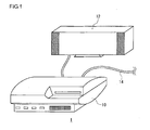
- Fig. 1 shows an environment in which an image processing system 1 according to an embodiment of the present invention is used.
- the image processing system 1 comprises an image processing device 10 configured to run image processing software and a display device 12 configured to output a result of processing by the image processing device 10.
- the display device 12 may be a television set provided with a display for outputting an image and a speaker for outputting sound.
- the display device 12 may be connected to the image processing device 10 by cable or connected wirelessly using, for example, wireless LAN (Local Area Network).
- the image processing device 10 in the image processing system 1 may be connected to an external network such as the Internet by a cable 14 and download and acquire hierarchized compressed image data.
- the image processing device 10 may be connected to an external network wirelessly.
- the image processing device 10 may be a game device so that image processing functionality is achieved by loading an application for image processing.
- the image processing device 10 may be a personal computer so that image processing functionality is achieved by loading an application for image processing.
- the image processing device 10 enlarges/reduces an image displayed on the display of the display device 12 or moves the image upward, downward, leftward, or rightward, in accordance with a user request. These processes will be generically referred to as "process to move the displayed image” hereinafter.
- process to move the displayed image When the user manipulates an input device by viewing an image displayed on the display, the input device transmits a request signal to move a displayed image to the image processing device 10.
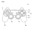
- Fig. 2 shows the appearance of the input device 20.
- the input device 20 is provided with directional keys 21, analog sticks 27a, 27b, and four control buttons 26, which are means for user control.
- the four buttons 26 comprises a circle button 22, a cross button 23, a square button 24, and a triangle button 25.
- the user control means of the input device 20 in the information processing system 1 is assigned the function of entering a request for enlarging/reducing a displayed image, and entering a request for scrolling upward, downward, leftward, or rightward.
- the function of entering a request for enlarging/reducing a displayed image may be allocated to the right analog stick 27b.
- the user can enter a request to reduce a displayed image by pulling the analog stick 27b toward the user and can enter a request to enlarge a displayed image by pushing it away from the user.
- the function of entering a request for moving a display area may be allocated to the directional keys 21. By pressing the directional keys 21, the user can enter a request for movement in the direction in which the directional keys 21 is pressed.
- the function of entering a request to change a displayed image may be allocated to alternative user control means.
- the function of entering a request for scrolling may be allocated to the analog stick 27a.
- the input device 20 has the function of transferring an input signal requesting to move a displayed image to the image processing device 10.
- the input device 20 is configured to be capable of communicating with the image processing device 10 wirelessly.
- the input device 20 and the image processing device 10 may establish communication using the Bluetooth (registered trademark) protocol or the IEEE802.11 protocol.
- the input device 20 may be connected to the image processing device 10 via a cable so as to transfer a signal requesting to move a displayed image to the image processing device 10 accordingly.
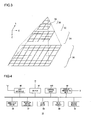
- Fig. 3 shows the hierarchical structure of image data used in the embodiment.
- the image data has a hierarchical structure comprising a 0-th layer 30, a first layer 32, a second layer 34, and a third layer 36 in the direction of depth (Z axis). While the figure only shows four layers, the number of layers is nonrestrictive.
- image data having such a hierarchical structure will be referred to as "hierarchical image data”.
- the hierarchical image data shown in Fig. 3 has a quadtree hierarchical structure.
- Each layer comprises one or more tile images 38. All of the tile images 38 are formed to have the same size having the same number of pixels. For example, an image includes 256 ⁇ 256 pixels.
- the image data in the respective layers are representations of an image in different resolutions.
- the original image in the third layer 36 having the highest resolution is reduced in a plurality of stages to generate the image data for the second layer 34, the first layer 32, and the 0-th layer 30.
- the resolution in the Nth layer (N is an integer equal to or greater than 0) may be 1/2 the resolution of the (N+1)th layer in both the horizontal (X axis) direction and the vertical (Y axis) direction.
- the hierarchical image data is compressed in a predefined compression format and is stored in a storage device and is read from the storage device and decoded before being displayed on the display.
- the image processing device 10 is provided with the decoding function compatible with a plurality of compression formats.
- the device is capable of decoding compressed data in the S3TC format, JPEG format, JPEG2000 format. Compression may be performed for each tile image. Alternatively, a plurality of tile images included in the same layer or a plurality of layers may be compressed at a time.
- the hierarchical structure of hierarchical data is configured such that the horizontal direction is defined along the X axis, the vertical direction is defined along the Y axis, and the depth direction is defined along the Z axis, thereby building a virtual three-dimensional space.
- the image processing device 10 uses the amount of move to derive the coordinates at the four corners of a frame (frame coordinates) in the virtual space. Frame coordinates in the virtual space are used to generate a displayed image.
- the image processing device 10 may derive information identifying the layer and the texture coordinates (UV coordinates) in the layer.
- the combination of the information identifying the layer and the texture coordinates will also be referred to as frame coordinates.
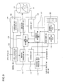
- Fig. 4 shows the configuration of the image processing device 10.
- the image processing device 10 comprises an air interface 40, a switch 42, a display processing unit 44, a hard disk drive 50, a recording medium loader unit 52, a disk drive 54, a main memory 60, a buffer memory 70, and a control unit 100.
- the display processing unit 44 is provided with a frame memory for buffering data to be displayed on the display of the display device 12.
- the switch 42 is an Ethernet switch (Ethernet is a registered trademark), a device connected to an external device by cable or wirelessly so as to transmit and receive data.
- the switch 42 may be connected to an external network via the cable 14 so as to receive hierarchized compressed image data from an image server.
- the switch 42 is connected to the air interface 40.
- the air interface 40 is connected to the input device 20 using a predefined wireless communication protocol.
- a signal requesting to move a display image as input by the user via the input device 20 is supplied to the control unit 100 via the air interface 40 and the switch 42.
- the hard disk drive 50 functions as a storage device for storing data.
- the compressed image data received via the switch 42 is stored in the hard disk drive 50.
- the recording medium loader unit 52 reads data from the removable recording medium.
- the disk drive 54 drives and recognizes the ROM disk so as to read data.
- the ROM disk may be an optical disk or a magneto-optical disk.
- the compressed image data may be stored in the recording medium.
- the main controller 100 is provided with a multicore CPU.
- One general-purpose processor core and a plurality of simple processor cores are provided in a single CPU.
- the general-purpose processor core is referred to as a power processing unit (PPU) and the other processor cores are referred to as synergistic-processing units (SPU).
- PPU power processing unit
- SPU synergistic-processing units
- the main controller 100 is provided with a memory controller connected to the main memory 60 and the buffer memory 70.
- the PPU is provided with a register and a main processor as an entity of execution.
- the PPU efficiently allocates tasks as basic units of processing in applications to the respective SPUs.
- the PPU itself may execute a task.
- the SPU is provided with a register, a subprocessor as an entity of execution, and a local memory as a local storage area.
- the local memory may be used as the buffer memory 70.
- the main memory 60 and the buffer memory 70 are storage devices and are formed as random access memories (RAM).
- the SPU is provided with a dedicated direct memory access (DMA) controller and is capable of high-speed data transfer between the main memory 60 and the buffer memory 70. High-speed data transfer is also achieved between the frame memory in the display processing unit 44 and the buffer memory 70.
- the control unit 100 implements high-speed image processing by operating a plurality of SPUs in parallel.
- the display processing unit 44 is connected to the display device 12 and outputs a result of image processing in accordance with user request.
- the image processing device 10 is configured to load part of the compressed image data identified by a rule described later from the hard disk drive 50 into the main memory 60 in order to change a displayed image smoothly as the displayed image is enlarged/reduced or the display area is moved. Further, the device 10 is configured to predict an image to be displayed in the future based on the user's request to move the displayed image, and decode part of the compressed image data loaded into the main memory 60 and store the decoded data in the buffer memory 70. This allows instant switching of images used for creation of displayed image when the switching is required later.
- prefetch process the process of predicting a tile image displayed in the future and storing the tile image in the buffer memory 70
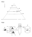
- Fig. 5 shows a prefetch process.
- Fig. 5 shows the structure of hierarchical data.
- the layers are represented as L0 (O-th layer), L1 (first layer), L2 (second layer), and L3 (third layer), respectively.
- the position in the depth (Z axis) direction indicates the resolution. The closer to L0, the lower the resolution, and, the closer to L3, the higher the resolution.
- the position in the depth direction represents the scale. Assuming that the scale of the displayed image in L3 is 1, the scale in L2 is 1/4, the scale in L1 is 1/16, and the scale in L0 is 1/64.
- the displayed image is enlarged. If the frame changes in the direction away from L3 toward L0, the displayed image is reduced.
- An arrow 80 indicates that an image movement request signal input by a user requests reduction in the displayed image and shows that reduction occurs across the scale 1/4 (L2).
- the position of L1, L2, which are made available as tile images 38, in the direction of depth is defined as the boundary of prefetching in the depth direction.
- the displayed image is generated by using the tile image in L2 (second layer). More specifically, the L2 image is used when the scale of the displayed image is between a switching boundary 82 and a switching boundary 84, the boundary 82 being between the image in L1 and the image in L2, and the boundary 84 being between the image in L2 and the image in L3. Therefore, when reduction of an image is requested as indicated by an arrow 80, the enlarged version of the image in L2 is turned into a reduced version and displayed.
- the image processing device 10 may delay generation of a displayed image requested by an image movement request signal by subjecting the image movement request signal from the input device 20 and a transfer function to convolution.
- the image processing device 10 also identifies the tile image 38 expected to be necessary in the future based on the image movement request signal and prefetches the identified tile image 38 from the main memory.
- the image processing device 10 reads the tile image 38 in L1, which is located in the direction of reduction, from the main memory 60, decodes the read image, and writes the decoded image in the buffer memory 70.
- a prefetch process in the depth direction Prefetching in the upward, downward, leftward, or rightward direction in the identical layer is also processed in a similar manner. More specifically, the prefetch boundary is set in the image data stored in the buffer memory 70 so that, when the display position determined by the image movement request signal exceeds the prefetch boundary, the prefetch process is started.
- Fig. 6 schematically shows the flow of image data according to the embodiment.
- Hierarchical data is stored in the hard disk drive 50.
- a recording medium mounted on the recording medium loader unit 52 or the disk drive 54 may store the data instead of the hard disk 50.
- the image processing device 10 may download hierarchical data from an image server connected to the device 10 via the network.
- the hierarchical data is compressed in a fixed-length format such as S3TC or in a variable-length format such as JPEG.
- part of the image data is loaded into the main memory 60, maintaining a compressed state (S10).
- An area to be loaded is determined according to a predefined rule. For example, an area close to the currently displayed image in the virtual space, or an area predicted to be frequently requested for display, from a viewpoint of the content of image or the history of browsing by the user, is loaded.
- the data is loaded not only when a request to change an image is originated but also at predefined time intervals. This prevents heavy traffic for loading processes from occurring in a brief period of time.
- Compressed image data is loaded in units of blocks having a substantially regular size. For this reason, the hierarchical data stored in the hard disk drive 50 is divided into blocks according to a predefined rule. In this way, data management in the main memory 60 can be performed efficiently. Even if the compressed image data is compressed in a variable-length format, the data as loaded would have an approximately equal size if the image is loaded in units of blocks (hereinafter, referred to as "image blocks"). Therefore, a new loading operation is completed basically by overwriting one of the blocks already stored in the main memory 60. In this way, fragmentation is unlikely to occur, the memory is used efficiently, and address management is easy.
- the buffer memory 70 includes at least two buffer areas 72 and 74.
- the size of the buffer areas 72 and 74 is configured to be larger than the size of the frame memory 90 so that, when the signal entered via the input device 20 requests change of a certain degree or less, the image data loaded in the buffer areas 72 and 74 is sufficient to create a displayed image.
- One of the buffer areas 72 and 74 is a display buffer used to store an image for creation of displayed image and the other is a decoding buffer used to make available an image predicted to become necessary subsequently.
- the buffer area 72 is a display buffer
- the buffer area 74 is a decoding buffer
- a display area 68 is being displayed.
- the image stored in the decoding buffer in a prefetch process may be of the same layer as the image stored in the display buffer or of a different layer with a different scale.
- the image of the display area 68 is rendered in the frame memory 90 (S14). Meanwhile, the image of a new area is decoded as necessary and stored in the buffer area 74.
- the display buffer and the decoding buffer are switched depending on the timing of completion of storage or the amount of move of the display area 68 (S16). This allows smooth switching between displayed images in the event of the movement of a display area or change in the scale.
- the process described so far concerns a mode in which the frame coordinates are moved in accordance with a user request to move an image in a virtual space formed by a single set of hierarchical data as shown in Fig. 5 so as to move, enlarge, or reduce the display area of the image.
- the embodiment further uses a plurality of sets of hierarchical data for display and allows a displayed image to go back and forth between the hierarchical data sets.
- Fig. 7 schematically shows a relation between a plurality of sets of hierarchical data used for display according to the embodiment.
- two triangles indicate different hierarchical data 150 and 152.
- Each of the hierarchical data 150 and 152 is actually configured such that different image data of different resolutions are discretely located in the Z-axis direction of the figure, as shown in Fig. 3 .
- the displayed image moves in a Z-axis direction of the figure. Meanwhile, the displayed image moves in the horizontal direction when the request is to move the displayed image upward, downward, leftward, or rightward.
- the embodiment generates a state in which the two sets of hierarchical data 150 and 152 overlap in the virtual space as shown.
- the hierarchical data 150 and 152 may comprise data representing the same object in different ranges of resolutions. Alternatively, they may represent completely different objects.
- the hierarchical data 150 represents data for a world map and the hierarchical data 152 represents data for a Japanese map
- transition from the hierarchical data 150 to the hierarchical data 152 takes place as the user enlarges an area of Japan in the world map.
- a detailed map of Japan will be shown.
- the hierarchical data 150 represents data for a menu screen and the hierarchical data 152 represents data for a manual that explains the icons displayed in the menu screen
- a user request to enlarge a desired icon in the menu screen switches the display to the image of the manual explaining the function corresponding to the icon.
- the hierarchical data used in rendering is switched, prompted by the movement of a displayed image in the virtual space, i.e., an input of a request for move, enlarge, or reduce the displayed image.
- Switching can take place only by using a basic operation for controlling an image currently displayed. This provides highly friendly user interface that does not require steps of, for example, displaying a menu screen for switching or selecting from the menu.
- the inventive approach For creation of a content that allows continuous enlargement from an image of a world map to a high-resolution image that gives a view of buildings or streets, the inventive approach saves data for a region (e.g., ocean region) that does not need enlargement, by maintaining separate hierarchical data depending on the required range of resolutions, and can reduce the data size significantly as compared with a case of building a single huge hierarchical data. Moreover, the inventive approach allows completely different images to be displayed continuously and so can be applied to a variety of image representation and content creation.
- a region e.g., ocean region
- the area in the image currently displayed that initiates switching to a different set of hierarchical data, or the resolution that initiates the switching, are predefined as "link information" indicated by a line 154 in Fig. 7 .
- switching from the hierarchical data 150 to the hierarchical data 152 takes place at a position characterized by the resolution z1 defined along the Z-axis and located on a horizontal plane denoted by a line 154 (see Fig. 3 ).
- switching between hierarchical data sets will be referred to as "link”.
- Fig. 8 illustrates how images are displayed when a link is established between hierarchical data sets.
- three sets of hierarchical data namely, images 156, 158, and 160 are used for display. It will be assumed that a link is established between an area 162 in the image 156 and an area 163 in the image 158, and a link is established between an area 164 in the image 156 and an area 165 in the image 160. Such areas will hereinafter be referred to as "link areas”.
- a link area corresponds to the line 154 of Fig. 7 .
- the hierarchical data used for display is switched from the image 156 to the image 158 so that the link area 163 in the image 158 is displayed accordingly (arrow A).
- the hard disk drive 50 stores data for the image 158, which shows an area around the pentagon in the image 156 at a higher resolution, in the form of a different hierarchical data.
- the link area 162 and the link area 163 are configured to have the same angle of view.
- An image at a resolution higher than the highest resolution defined in the hierarchical data for the image 156 can be displayed using the hierarchical data for the image 158 in continuation from the image 156.
- transition indicated by the arrow a of Fig. 7 occurs merely by zooming to the pentagon. Therefore, the user need not be aware of the switching of hierarchical data.
- a link indicated by an arrow B opposite in direction to the arrow A is also established between the link area 162 and the link area 163.
- the hierarchical data used for display is switched from the image 158 to the image 156 so that the link area 162 in the image 156 is displayed accordingly (arrow B).
- continuous reduction is possible merely by reducing the displayed image from the image 158 and without causing the user to be aware of the switching of hierarchical data.
- Transition from the link area 164 to the link area 165 occurs similarly.
- the hierarchical data is switched so that the link area 165 in the image 160 is displayed. This allows an image with a higher resolution than that of the image 156 to be displayed.
- a displayed image may be determined to "overlap" a link area even if the displayed image is not strictly aligned with the link area. Therefore, a rule that determines that overlapping occurs, for example, when the displayed image is located within a certain range from the link area, may be established.
- the control unit 100 comprises an input information acquisition unit 102 for acquiring information entered by the user via the input device 20, a compressed data division unit 104 for dividing hierarchical data into image blocks, a loaded block determination unit 106 for determining an image block that should be newly loaded, and a loading unit 108 for loading a necessary image block from the hard disk drive 50.
- the control unit 100 further comprises a prefetch processing unit 110 for performing a prefetch process, a link determination unit 116 for determining whether the data that should be loaded or decoded is located in the hierarchical data at the destination of the link, a decoding unit 112 for decoding compressed image data, and a displayed image processing unit 114 for rendering a displayed image.
- the control unit 100 further includes a scenario interpretation unit 117 configured to interpret scenario information set up in the control unit and control the link determination unit 116, the loading unit 108, and the displayed image processing unit 114.
- the elements depicted in Fig. 9 . as functional blocks for performing various processes are implemented in hardware such as a central processing unit (CPU), memory, or other LSI's, and in software such as a programs etc., loaded into the memory.
- the control unit 100 includes one PPU and a plurality of SPUs.
- the PPU and the SPUs form the functional blocks alone or in combination. Therefore, it will be obvious to those skilled in the art that the functional blocks may be implemented in a variety of manners by hardware only, software only, or a combination of thereof.
- the hard disk drive 50 stores a plurality of sets of hierarchical data 101 in which links are set up.
- the main memory 60 stores a link definition file 118.
- the link definition file 118 is a file that records link information established between hierarchical data sets.
- the link definition file as attached to the body of the hierarchical data 101 may be loaded from the hard disk drive 50.
- a description of a scenario definition file 119 stored in the main memory 60 will be described later.
- the input information acquisition unit 102 acquires an instruction entered by the user via the input device 20 to start/terminate displaying an image, move the display area, enlarge or reduce the displayed image, etc.
- the input information acquisition unit 102 may delay the image movement request signal in accordance with the predefined maximum value of the speed with which to move the displayed image, the transfer function used for convolution of the image movement request signal, etc.
- the transfer function may be a Gaussian function.
- the image processing device 10 uses the delay to secure time for a process of prefetching image data, or time required to reconstruct the image or moving image at the link destination (described later) or to active an application. This allows smooth image display in response to a user request.
- the compressed data division unit 104 reads hierarchical data from the hard disk drive 50, generates image blocks by dividing the data according to a predefined rule described later, and stores the divided data in the hard disk drive 50. For example, when the user uses the input device 20 to select one of the hierarchical data stored in the hard disk drive 50, the unit 104 acquires the information accordingly from the input information acquisition unit 102 and starts a dividing process. Alternatively, the hard disk drive 50 may store hierarchical data that is divided into image blocks right from the start. If such hierarchical data is used for display, the compressed data division unit 104 may not be operated.
- the loaded block determination unit 106 verifies whether there are image blocks that should be loaded from the hard disk drive 50 into the main memory 60 or not, and determines the image block that should be loaded next, issuing a load request to a loading unit 108. In this process, the load block determination unit 106 places an inquiry to the link determination unit 116 to inquire whether the image block that should be loaded includes a image block of a different hierarchical data at the destination of the link, or not.
- the loaded block determination unit 106 performs the above-mentioned verification and determination according to a predefined timing schedule while the loading unit 108 is not performing loading process. For example, verification and determination may be performed when a predefined period of time elapses or when the user requests to move the image.
- the loading unit 108 performs an actual loading process in accordance with a request from the loaded block determination unit 106.
- the image block including the destination image area is not stored in the main memory 60 upon occurrence of the user request to move the displayed image, it is necessary to perform the steps of loading the image block from the hard disk drive 50, decoding the necessary area, and rendering the displayed image in one setting.
- the loading process may represent a bottle neck in this case, with the result that the response to the user request may become poor.
- the following policies are observed to load blocks, namely, (1) image blocks are loaded so as to exhaustively cover areas that are highly likely to be displayed, (2) loading takes place on a steady basis so that heavy traffic for loading processes is prevented from occurring in a brief period of time.
- the prefetch processing unit 110 predicts the image area expected to be needed for rendering of a displayed image in the future, in accordance with the frame coordinates of the currently displayed image and information related to the user request to move the displayed image, and supplies the resultant information to the decoding unit 112. However, prediction is not performed immediately after an image is started to be displayed, or when the destination image cannot be rendered using the image stored in the buffer memory 70. In these cases, the prefetch processing unit 110 supplies information on an area that includes the image currently necessary to render the displayed image to the decoding unit 112. The prefetch processing unit 110 places an inquiry the link determination unit 116 to inquire whether the predicted image area or the image area necessary to render the currently displayed image is included in the other hierarchical data set at the destination of the link, or not.
- the link determination unit refers to the link definition file 118 stored in the main memory 60 and determines whether an image block in the hierarchical data at the destination of the link is included in the image block that should be loaded in response to the inquiry from the load block determination unit 106. If the image block is included, the link determination unit 116 converts the coordinates of a point in the currently displayed hierarchical data that should be loaded into the coordinates defined in the hierarchical data at the destination of the link and returns the converted coordinates to the load block determination unit 106 along with the pre-conversion coordinates and the file name of the hierarchical data at the destination of the link.
- the link determination unit 116 also determines whether the area necessary for rendering includes an area in the hierarchical data at the destination of the link in response to an inquiry from the prefetch processing unit 110. If an area is included, the link determination unit 116 returns information related to the coordinates of the link area at the destination of the link. An example of setting a link will be described later.
- the decoding unit 112 reads and decodes a part of the compressed image data from the main memory 60 by referring to the information on the image area acquired from the prefetch processing unit 110 and stores the decoded data in the decoding buffer or the display buffer.
- the displayed image processing unit 114 determines the frame coordinates of the new displayed image in accordance with user request to move the displayed image, reads the corresponding image data from the display buffer of the buffer memory 70, and renders the image in the frame memory 90 of the display processing unit 44.
- the scenario interpretation unit 117 interprets the scenario file 119 stored in the main memory 60 and controls the displayed image in order to achieve continuous transition in the displayed image. Details will be described later.
- Figs. 10-13 show a method of defining an area (frame) in an image.
- Fig. 10 shows a relation between a reference frame and an image.
- a reference frame 264 for an image 156 has a center that is aligned with the center of the image 156 and is formed as a rectangle circumscribing the image 156 and having a predetermined aspect ratio.
- the aspect ratio may have a predetermined value.
- the aspect ratio may be identical to the aspect ratio of the display displaying the image or the aspect ratio of the display area on the display. It will be set that the frame maintains the ratio even when the displayed image is enlarged or reduced.
- the frame is defined using four parameters including a horizontal offset, a vertical offset, a magnification factor, and an angle of rotation from the reference frame.
- Fig. 11 describes how frame is defined when the reference frame is translated.
- values are substituted into the vertical offset parameter and the horizontal offset parameter.
- the horizontal component offset_x and the vertical component offset_y of the distance from the center of a frame 272 to the center 270 of the image 156, i.e., the center of the reference frame represent the values of the horizontal offset and the vertical offset, respectively. Therefore, the frame 262 is represented as (offset_x, offset_y, 1.0, 0).
- Fig. 12 shows how a frame is defined when the reference frame is not translated but only the magnification factor is changed.
- the magnification factor of a frame 266 with respect to the reference frame is substituted into the magnification factor parameter. If the frame 266 of Fig. 12 is 0.5 times the reference frame of Fig. 10 in size, the frame 266 is represented as (0, 0, 0.5, 0).
- Fig. 13 shows how a frame is defined when the reference frame is not translated but rotated.
- the angle of rotation 282 of a frame 280 with respect to the reference frame is substituted into the rotation angle parameter.
- the frame 280 is represented as (0, 0, 1.0, 0.25).
- the frame for the displayed image is represented by four parameters without exception.
- the set of four parameters will hereinafter be referred to as "frame definition parameters".
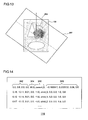
- Fig. 14 shows an example of data structure of a link definition file 118.
- One row of the link definition file 118 corresponds to a link, i.e., to a description of switching from a given hierarchical data set to another.
- Each row comprises four fields including a link source image frame field 302, an effective scale range field 304, a link destination file field 306, and a link destination image frame field 308.
- the link source image frame field 302 designates a displayed area in the image being displayed at which switching of hierarchical data sets occurs, i.e., a link area, using the above-mentioned frame definition parameters.
- the frame as defined in the illustration corresponds to the frame of the link area 163 at the source of the link indicated by the arrow B in Fig. 8 .
- the effective scale range field 304 designates a range of magnification factors in which the link is effective.
- the range starts with the magnification factor defined in the link source image frame field 302. Referring to the first row of Fig. 14 , the magnification factor of the link area indicated in the link source image frame field 302 is "2.0" and the value of the effective scale range field 304 is "98.0". Therefore, the link is defined as being effective and switching of hierarchical data sets occurs provided that the magnification factor of the displayed image is 2.0-100.0.
- the image 158 is switched to the image 156 upon zoom-out of the displayed image, i.e., when the frame magnification factor is started to be increased while a frame smaller than the link area 163 in the image 158 is being displayed until the frame is aligned with the link area 163. Therefore, a positive value is defined in the effective scale range field 304 in order to active the link when the magnification factor is 2.0 or greater. This will allow the link to be effective even when the image 158 is displayed at an enlarged magnification factor and then the displayed image is moved closer to the link area 163.
- the image 156 is switched to the image 158 upon zoom-in of the displayed image, i.e., when the frame magnification factor is started to be decreased while a frame larger than the link area 162 in the image 156 is being displayed until the frame is aligned with the link area 162. Therefore, a negative value such as "-1.0" is defined in the effective scale range field 304, as indicated at the second row in Fig. 14 .
- the link destination file field 306 designates the file name of the hierarchical data at the destination of the link. In the example of the link indicated by the arrow B in Fig. 8 , the file name of the hierarchical data for the image 156.
- the link destination image frame field 308 designates the frame definition parameters of the image displayed when the hierarchical data is switched, i.e., the frame of the link area at the destination of the link.
- a link definition file is created for each set of hierarchical data at the source of the link. For example, information on the links indicated by the arrows A and C in Fig. 8 are described in the link definition file for the hierarchical data 156, and information on the link indicated by the arrow B is described in the link definition file for the hierarchical data 158.
- the files are stored in association with the corresponding hierarchical data. In this way, links established bidirectionally can behave independently. For example, the link areas A and B involved in the transition indicated by the arrow A in Fig. 8 and the link areas A and B involved in the transition indicated by the arrow B may be different in the area and the resolution. In the example of Fig. 8 , no link definition files are established for the image 160. Therefore, the user is expected to enjoy himself or herself by displaying the image 160 after making a transition to the image 160.
- the link determination unit 116 can verify whether the area predicted to be used through a prefetch process includes the link area defined in the link definition file, in response to an inquiry from the prefetch processing unit 110. If the link area is included, the link determination unit 116 returns the file name of the hierarchical data at the destination of the link, and the frame definition parameters of the link area at the destination of the link. The prefetch processing unit 110 delivers the information to the decoding unit 112 as in the case where the link area is not included. The decoding unit 112 reads the data for the link area at the destination of the link from the main memory 60 and decodes the read data.
- the link determination unit 116 verifies whether the point that should be loaded is included in the link area in response to an inquiry from the load block determination unit 106. If the link area is included, the link determination unit 116 returns the file name of the hierarchical data at the destination of the link. In this process, the coordinates of the point to be loaded defined in the image at the source of the link are converted into coordinates in the image at the destination of the link and the resultant coordinates are also returned. Of the hierarchical data for the image at the destination of the link, the load block determination unit 106 loads the image block including the point that should be loaded and of which coordinate is obtained by the conversion from the hard disk drive 50 into the main memory 60.
- FIG. 15 schematically shows points that should be loaded when a link is established between two sets of hierarchical data. Basically, it is desirable that compressed data for an image surrounding the currently displayed image be loaded into the main memory 60.
- the neighborhood in the vertical and horizontal direction (X-axis, Y-axis) in the image of a layer and in the direction of the depth (Z-axis) of the hierarchical structure may be encompassed.
- the neighborhood in the Z-axis direction signifies enlarged or reduced images that include the displayed image or the neighborhood thereof.
- two triangles indicate different hierarchical data 184 and 186, as in Fig. 7 .
- a link indicated by a line 188 is established between the hierarchical data 184 and 186.
- the image block that includes points indicated by blank circles 192 and solid circles 194 in the figure is loaded into the main memory 60.
- points within a predetermined range from the currently displayed image area are determined as being points that should be loaded.
- Determination of points that should be loaded and loading of the image block including the points may be performed on a steady basis at predetermined time intervals.
- image blocks are stored in the hard disk drive 50 such that the hard disk drive 50 also stores information mapping an area in an image of each image block to an area storing the image block.
- the main memory 60 stores information mapping an area in an image in each image block to an area storing the image block.
- the load block determination unit 106 periodically verifies whether the image block including the point that should be loaded is stored in the main memory 60. If the image block is not stored, the load block determination 106 determines the image block as a target of loading. By loading image blocks steadily, wait time to display an image required as a result of a loading process is reduced.
- the data for the link destination may be loaded in preference to the currently displayed hierarchical data 184. This allows a new image at the destination of the link to be displayed smoothly even if transition to the link destination occurs immediately.
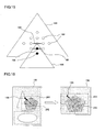
- FIG. 16 shows a method of converting XY coordinates in the image at the source of the link into those of the image at the destination of the link. Referring to Fig. 16 , it will be assumed that a link is established such that a link area 200 in the image 156 is switched to a link area 204 in the image 158, and that a point 196 defined in the image 156 corresponds to a point 198 defined in the image 158.
- the length of a side of the link area 200 is (La_sx, La_sy)
- the coordinates of the center of the area is (La_x, La_y)
- the coordinates of the point 198 is (Pb_x, Pb_y)
- the length of a side of the link area 204 is (Lb_sx, Lb_sy)
- the coordinates of the center of the area is (Lb_x, Lb_y)
- Fig. 17 shows a method of converting the Z coordinate in the image at the source of the link into that of the image at the destination of the link.
- a link indicated by a line 208 is established between the hierarchical data 184 and the hierarchical data 186.
- the position of the line 208 represents a link area in the hierarchical data 184 and a link area in the hierarchical data 186.
- the variable has a common axis in the Z-axis direction not dependent on the number of layers included in the hierarchical data.
- two sets of hierarchical data are dealt with as targets of display.
- the device according to the embodiment is capable of displaying an object shown in another image on an enlarged scale or displaying a totally different content, prompted by an input of a request to move the displayed image.
- Three or more sets of hierarchical data may be the targets of display.
- links may be established cyclically such that the initial image is again displayed as the magnification factor is enlarged. In this case, as a plurality of sets of hierarchical data for which sequentially links are established are enlarged in succession, the initial hierarchical data may be displayed.
- the display may return to a reduced version of the initially displayed image.
- the link destination file field in the link definition file of the hierarchical data may designate the file name for the hierarchical data itself.
- a prefetch process predicts a change in the displayed image to a link area.
- the neighborhood around the currently displayed image in the virtual space is loaded into the memory regardless of the hierarchical data.
- smooth switching between images can be presented by adjusting the transfer function.
- smooth switching may be presented by applying any of generally known visual effects used in a switcher adapted for moving images (e.g., cross fade, dissolve, wipe, and page flipping using polygon mesh) to the images.
- Moving image data may be defined as the destination of a link.
- the destination of the link may be considered as hierarchical data comprising a single layer of moving image data.
- a link to the moving image data may be defined in an area in a still image.
- the data structure as shown in Fig. 14 may be used in the link definition file.
- the link destination file field 306 designates the file name of the moving image file. If the resolution and display area of the moving image are fixed, the link destination image frame field 308 may be invalidated.
- the feature described above may be used to add flair to the display.
- several still images e.g., gravure pictures
- an application file may be designated in the link destination file field 306 in the link information so that the application is started by zooming into a certain area in the image.
- Fig. 18 shows an example of an image in which a link area is defined.
- a plurality of link areas 352a, 352b, and 352c are defined in an image 350.
- zooming to the link area 352a a detailed image of the area or related information is displayed, moving images are played back, or an application is started.
- the link areas are limited as in the image 350, the user may be guided to move the displayed image in order to reduce the user trouble required for alignment. Even if the link areas are not limited, such a function is useful to guide the displayed image according to predefined intention.
- a frame definition parameters used in the link information are used.
- a file like that of link information is prepared in which frame definition parameters in the format (horizontal offset, vertical offset, magnification factor, rotation angle) are defined for each area to which the display should be guided (hereinafter, referred to as guidance area).
- the file is stored as a scenario definition file 119 in the main memory 60 of Fig. 9 .
- the display area enters into a predetermined range in the virtual space with respect to a frame defined in the scenario definition file 119, the displayed image is guided to the guidance area.
- the process is achieved through the steps as already described above by virtually generating a signal requesting movement of an image to the guidance area.
- the "predetermined range" is also defined in the scenario definition file using frame definition parameters.
- Fig. 19 shows how the displayed image is guided within a given hierarchical data to effect transition between different layers for display.
- hierarchical data 360 corresponds to an image 362.
- guidance areas 374 and 376 indicated by lines 368 and 370, respectively, are defined in the scenario definition file 119 using frame definition parameters and that an area 372 currently displayed corresponds to a line 366.
- the displayed image As the user enlarges the displayed image, starting in the area 372, the displayed image is guided to the guidance area 374 (arrow D) when the displayed image enters into a predetermined range from the guidance area 374.
- the displayed image is guided to the guidance area 376 (arrow E).
- the mode of display as described above can be used for various purposes depending on the content of image displayed.
- the user may wish to enlarge only a selected area in a scenery photo or a portrait.
- an attempt to enlarge a desired area may result in undesired portion of the image being displayed and it may be difficult to search for the desired area at the magnification factor then in use.
- the area can be accurately enlarged as the user moves the displayed image roughly toward that area and enters a request for enlargement.
- Guidance of the displayed image to the guidance area may not only occur when the displayed image is in the neighborhood of the guidance area. For example, the display area may be moved when a predetermined button is pressed regardless of the position of the currently displayed image.
- Guidance may occur not only to a different layer.
- the sequence of display within the same layer may be designated in the guidance.
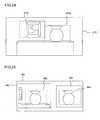
- Fig. 20 shows how the displayed image undergoes transition when guidance to a different layer and guidance to another area in the same layer are combined. For example, it assumed that a single page of newspaper or a magazine is displayed using the hierarchical data 380.
- An area containing characters expected to be browsed upon enlargement is defined as guidance area article by article.
- a guidance area 392 indicated by a line 386 represents such an area.
- a plurality of guidance areas are defined so that the user can track the article from start to end in a layer having the resolution that allows the user to decipher characters.
- a guidance area 394 indicated by a line 388 and a guidance area 396 indicated by a line 390 are such areas.
- the user initially displays an area 382 of the entirety of the page indicated by a line 384 and then enlarges the displayed image by bringing it closer to a desired article. This will guide the user to the guidance area 392 defined in the article (arrow F). Further enlargement results in guidance to the guidance area 394 at the head of the article (arrow G). As the user reading the sentence in the guidance area 394 designates a direction or presses a predetermined button, the user is guided to the guidance area 396 showing the continuation of the article (arrow H).
- the sequence of display is defined as well as frame definition parameters.
- a control key for designating the movement of the display area as described above is defined. For example, in the case of sentences in a multiple column layout (e.g., a newspaper article), the display area need to be moved from right to left, followed by the movement of the area below from right to left again.
- the user need not look for a position in an enlarged image to which the displayed image should be moved.
- guidance may occur when the currently displayed image enters into a predetermined range from the guidance area even in the case of movement within the same layer.
- Figs. 19 and 20 show transition of the displayed image within a given hierarchical data set for brevity. If a link to another hierarchical data set is defined in the transition, the display should naturally make transition to the other hierarchical data.
- the above-described example is directed to guiding the displayed image when the user enters a request to move, enlarge, or reduce the image.
- the embodiment also requires providing the function of causing the displayed image to make transition to a registered guidance area at predetermined time intervals. In this case, the user may only need to enter a request to run such a mode.
- the function provides a novel method of presenting source still images as if they are moving images. For example, the function enables showing images for promoting the sale of a magazine, or continuous browsing of photos.
- the frame definition parameters, the sequence of display, and the display time of each images are defined in the scenario definition file 119.
- the scenario definition file 119 may describe a process for detailed control of the transition of the image using a markup language such as XML.
- the scenario interpretation unit 117 reads the script from the main memory 60, interprets the script, and controls the displayed image by requesting the displayed image processing unit 114, the link determination unit 116, and the loading unit 108 to perform a process as appropriate.
- Fig. 21 is a flowchart showing the flow of steps described in this case.
- Hierarchical data is designated (S20).
- a single set of hierarchical data representing a single image may be designated.
- a block of a plurality of sets of hierarchical data in which a link is defined may be designated.
- the image to be displayed is designated using frame definition parameters (S22).
- an effect process applied when the image is displayed is designated as appropriate (S24).
- a cross fade process may be designated, or a process of reducing the previous image progressively and enlarging the current image may be designated.
- Time consumed for transition to the display of next image and the process for complementation between the current image and the next image are designated (S26).
- the "next image” may be an image in the same hierarchical data but in a different Layer (e.g., an enlarged version or a reduced version of the current image) or an image at the destination of the link.
- the "next image” may be an image in another set of hierarchical data.
- a method generally used in animation technique may be employed as a method of complementation between images, by using the current image and the next image as key frames.
- Steps S20 and S26 may be grouped into a block.
- the scenario is written to repeat the block if there are images in a different set of hierarchical data that are desired to be displayed in succession.
- the prefetch processing unit 110 places an inquiry to the link determination unit 116 and requests the decoding unit 112 to perform a decoding process. This will easily achieve a mode of display in which the designated images changes as the displayed image according to a sequence.
- the scenario definition file may designate the number identifying the layer in the hierarchical data used in rendering the image along with the frame definition parameters.
- scenario definition file 119 written in XML.
- (3)-(7) designate hierarchical data used in the content.
- (8) designate the initial position of the image.
- (9)-(13) designate the image of the hierarchical data displayed as an index as being the image that should be used initially, and the display area thereof.
- (14)-(31) designate data shifting by zooming to the image of the hierarchical data for the front cover of a book using camera animation. Of these lines, (14)-(26) designate camera animation by describing key frames.
- (27)-(31) designate the image of the hierarchical data displayed and the display area thereof. A link is established using the display area.
- (32)-(38) designate switching to the image of the hierarchical data including a link to moving images and that the moving images are displayed on an enlarged scale.
- (32)-(35) designate a link to the moving image in the same way as a link to the hierarchical data.
- (36) designates an effect applied used for rendering when the screen is switched.
- (39)-(43) designate displaying a copyright notice of the moving images while the moving images are being displayed.
- (40)-(41) designate displaying an ordinary image not having a hierarchical structure.
- the embodiment facilitates various image representations using a plurality of sets of hierarchical data as sources, by creating the link definition file or the scenario definition file. Therefore, an ordinary user may use hierarchical data provided as content over the network or in a recording medium to create unique content. The content created in this way may be distributed.
- Fig. 22 schematically shows an example of a mode of distributing data to implement the embodiment.
- servers 400, 402, and 404 are connected via the network 420.
- the server may be that of a content creator or, alternatively, an information terminal of an ordinary user. Still alternatively, a recording medium such as a CD-ROM or DVD may be used in place of a server.
- the server 400 provides a content comprising hierarchical data 406a and an attribute file 408a attached to the hierarchical data. A description on the attribute file 408a will be given later.
- the server 402 provides a content comprising hierarchical data 406b formed of a plurality of sets of hierarchical data, link definition files 410b, 410c that define information on a link between the hierarchical data sets, a scenario definition file 412b, and an attribute file 408b.
- the link definition files 410b and 410c are attached to the individual hierarchical data sets, as described above. Meanwhile, a scenario definition file takes advantage of the link thus set up and is capable of establish setting across hierarchical data. Therefore, the scenario definition file is attached to the whole set of hierarchical data in which links are established.
- the server 404 only provides the scenario definition file 412c.
- the data structure as illustrated is by way of example only.
- a scenario definition file may be attached to a single set of hierarchical data in which no links are established.
- a link definition file may be attached without a scenario definition file being attached.
- the contents stored in the server 400 and the server 402 can be displayed on a stand-alone basis.
- a set of content can be created by obtaining the scenario definition file 412c and the hierarchical data 406a and 406b designated in the file, if the sets of hierarchical data are included in the setting defined in the scenario definition file 412c in the server 404. Therefore, any of the data structures shown in Fig. 22 can be a unit of distribution as content.
- an attribute file is attached to the hierarchical data.
- Information recorded in the attribute file includes information related to the content (e.g., basic information such as the title of the content, creator, publisher, sponsor, date of creation, version, and language used; information on the owner of a right to the content or source material; information on refunding of the charge; information on the control of secondary use; information on ownership or copyright such as the expiration date, the number of times that copying is allowed, and the number of times that the possession of the content can be transferred; and rating).
- basic information such as the title of the content, creator, publisher, sponsor, date of creation, version, and language used
- information on the owner of a right to the content or source material information on refunding of the charge
- information on the control of secondary use information on ownership or copyright such as the expiration date, the number of times that copying is allowed, and the number of times that the possession of the content can be transferred; and rating.
- control attributes of the content e.g., authentication control information such as permission for connection or for use of data, encryption scheme, and signature; information related to billing such as information as to whether pay-as-you-go charge plan is in effect, information as to whether an upper limit is defined for the use of the content, information as to whether the content is made available free of charge, designation of currency or virtual currency, and information on payment method selected from charge, withdrawal, check, etc.; operating environment such as platform, OS, and recommended resources; and access control information such as target users, and areas or countries of valid use) may be attached. Further, data structure information may be attached to the attribute file.
- authentication control information such as permission for connection or for use of data, encryption scheme, and signature
- information related to billing such as information as to whether pay-as-you-go charge plan is in effect, information as to whether an upper limit is defined for the use of the content, information as to whether the content is made available free of charge, designation of currency or virtual currency, and information on payment method selected from charge, withdrawal, check, etc.
- the attached data structure information may include information on the content structure including the area for the attribute information, the area for the hierarchical data, and external reference link information; thumbnail information defining a name of content, a representative image, billing guidance, summary of attributes; and information on a location storing frame information.
- attaching the attributes information to the individual hierarchical data it is ensured that appropriate measures are taken when a content comprising a plurality of sets of hierarchical data using the hierarchical data with the attributes as a destination of a link is created and displayed. For example, attaching the attributes enables copyright notice to be displayed when a transition to a content protected by a copyright as a destination of a link occurs and enables a dialog for authentication to be displayed for a content configured such that authentication is necessary. Whether to display or not display the content may be determined according to the rating and a viewer profile. If the display is disabled, the image is not displayed.
- transition to the destination of the link does not take place even if the displayed image is within the link area so that only the image from the initial hierarchical data may is enlarged or reduced.
- Processes according to attribute information can be implemented using the same configuration used in the process of displaying an ordinary content.
- the plurality of hierarchical data in which a link is defined form a single content as a whole so that the attribute file is attached not only to the individual hierarchical data but also the entirety of the plurality of sets of hierarchical data.
- Fig. 23 shows the configuration of an image processing device provided with the function of assisting content creation according to the embodiment.
- An image processing device 500 shown in the figure may further have the same configuration as the image processing device 10 shown in Fig. 4 .
- Fig. 23 depicts only those functional blocks provided to implement the embodiment. Therefore, a control unit 502 of Fig. 23 may be implemented by the same processor as the control unit 100 shown in Fig. 9 . Alternatively, the control unit 502 may be implemented as a separate device.
- the image processing device 500 is provided with one or a combination of the following functions.
- the image processing device 500 is provided with an input device 520, a control unit 502, a hard disk drive 550, and a main memory 560.
- the hard disk drive 550 stores existing hierarchical data sets 551. A link may be established between hierarchical data sets.
- the input device 520 is an interface that allows the user to enter selection of the above-mentioned functions, selection of an image area, and various setting. For example, the input device 520 may have the appearance shown in Fig. 2 .
- the control unit 502 comprises an input information acquisition unit 504, a target image display unit 506, and a definition information registration unit 508.
- the input information acquisition unit 504 acquires information entered by the user using the input device 520 and requests the target image display unit 506 and the definition information registration unit 508 to perform a process as appropriate.
- the target image display unit 506 When the user provides an input requesting a guidance area or a link area to be defined, the target image display unit 506 reads the hierarchical data for the image selected by the user from the hard disk drive 550 and displays. The target image display unit 506 moves the displayed image in accordance with a user request to move the screen, or display a rectangle for designating an area in accordance with positional information of a pointer.
- the definition information registration unit 508 acquires the frame definition parameters of the area, generates a link definition file 562 or a scenario definition file 564, and stores the generated files in the main memory 560.
- the definition information registration unit 508 selects the resolution of the images as appropriate, creates hierarchical index image data 566 showing an arrangement of the images in a predetermined format, and stores the index image data in the main memory 560.
- a link definition file 562 in which links are defined between the generated hierarchical index image data and the hierarchical data for the individual images included in the index (hereinafter, referred to as "individual image") is created at the same time and stored in the main memory 560.
- the link definition file 562, the scenario definition file 564, and the index image data 566 may not only be stored in the main memory 560 and used for display but also stored in the hard disk drive 550 or another recording medium. In this process, the files 562 and 564, the data 566, and the hierarchical data subject to the definition are grouped to form a single content.
- Fig. 24 illustrates steps of the process, noted in "1" above, of acknowledging the definition of a guidance area, and creating and updating a scenario definition file.
- the user selects the hierarchical data for the target image using the input device 520.
- the target image display unit 506 obtaining the information from the input information acquisition unit 504 reads the hierarchical data from the hard disk drive 550 and displays the data accordingly.
- An image 570 of Fig. 24 shows the entirety of the selected image.
- the user uses the input device 520 to provide a request to move the image while viewing the display by the target image display unit 506.
- a rectangular surrounding the area may be rendered using a pointer operation, prompting the user to press the definition button.
- the definition information registration unit 508 acquires the frame definition parameters of the area and records the parameters in the scenario definition file 564.
- the user selects another area 574 as needed and presses the definition button.
- the definition information registration unit 508 adds the frame definition parameters of the selected area in the subsequent line in the scenario definition file 564.
- all desired areas are recorded in the scenario definition file 564.
- the scenarios definition file 564 thus generated, the areas desired to be displayed are sequentially displayed at a desired resolution in the order of areas 572, 574, ..., as described above.
- a markup language that describes the process of controlling display (e.g., display time of each area, animation process for interpolating between the images, and effect process) may be generated.
- a variation of image processing using sample images may be presented, prompting the user to select a desired process.
- the selected process is recorded in the scenario definition file 564 along with the frame definition parameters of the guidance area.
- Fig. 25 illustrates steps of the process, noted in "2" above, of acknowledging the definition of a link area, and creating and updating a link definition file.
- the user selects two sets of hierarchical data for two images which are the targets to be linked, using the input device 520.
- the target image display unit 506 obtaining information from the input information acquisition unit 504 reads the hierarchical data from the hard disk drive 550 and displays the data using two screens.
- Images 582 and 584 of Fig. 25 show selected images.
- the user uses the input device 520 to provide a request to move the image 582 while viewing the display by the target image display unit 506 and causes an image including the area 586 desired to be defined as a link area to be displayed.
- the user then causes a rectangular surrounding the area to be rendered using a pointer operation so as to select the area.
- an area 588 in the image 584 is selected.
- the user presses a predetermined definition button.
- the definition information registration unit 508 acquires the frame definition parameters of the areas 586 and 588, and records the parameters in the link definition file 562 in the form of the data structure as shown in Fig. 14 .
- the definition information registration unit 508 may collect information that should be designated in the effective scale range 304 and the link destination file field 306 by establishing a rule to display the link source image and the link destination image respectively on the left side and the right side of the target image display unit 506, and by allowing the user to select whether the link defines transition to enlarge the image or reduce the image.
- the link definition file 562 thus generated defines a link between the image 582 and the image 584. By zooming to the area 586 as described above, transition to the hierarchical data for the image 584 occurs for display of the image, allowing a magnified view of the image.
- the description above concerns defining a link between images.
- the destination of the link is not limited to an image and may be data for moving images, applications, audio, music, text, etc.
- the link source image may be displayed like the image 582.
- An icon representing data that represents a candidate of the destination of the link may be displayed in place of the image 584, allowing selection by the user.
- the link destination file field 306 in the link definition file 562 records the file name of the data corresponding to the selected icon.
- the link destination image frame field 308 may be invalidated.
- the frame definition parameters may be fine-adjusted in the virtual space so that the objects as shown in the two images are completely aligned, by extracting hint points in the objects displayed in each area and computing a matching score. This prevents displacement between the objects as shown from occurring due to the link during transition between the images and prevents the switching process from being visibly known.
- the process is useful not only in the case that the objects in the two images are identical but also in the case where two images are blended by cross fading (e.g., where a given object goes through a process of change).
- Fig. 25 shows selecting one area from each of the two images and defines a link accordingly. Alternatively, three or more images may be subject to selection, or a plurality of link areas may be defined in a single image. The aforementioned steps are repeated to achieve such a case.
- a dialog may be displayed that allows the user to enter information as to which of the information should be displayed and where the information should be displayed.
- the information entered by the user is recorded in the link definition file 562 and may be displayed as appropriate in the event of transition to the displayed image at the destination of the link.
- Fig. 26 illustrates the process, noted in "3" above, of acknowledging selection of a plurality of images and creating an index image that allows selection from the images by defining a link between the images.
- the user uses the input device 520 to select hierarchical data for a plurality of individual images for which an index is desired.
- the definition information registration unit 508 generates an index image in which individual images with appropriate resolutions (e.g., lowest-resolution images in the selected hierarchical data) are embedded as indices, such as the image 350 as shown in Fig. 18 as the index image data 566, and stores the data 566 in the main memory 560.
- areas 352a, 352b, and 352c represent individual images selected by the user.
- Hierarchical data 590 may be existent data selected by the user. For example, by selecting an image of the wall of an art museum as the hierarchical data 590 and arranging individual images within the frames on the wall, an image showing the individual images on the wall of the art museum is generated. Information as to where in the index image the individual images are arranged, the size of the images, etc. may be acknowledged from the user. In this case, the definition information registration unit 508 may generate index image data in which the individual images of sizes designated by the user are embedded at the positions designated by the user.
- the definition information registration unit 508 further generates a link definition file 562 in which links to the hierarchical data 592a, 592b, ..., 592n are defined at the positions in the hierarchical data 590 for the index image where the individual images are embedded, and stores the file 562 in the main memory 560.
- a link definition file 562 in which links to the hierarchical data 592a, 592b, ..., 592n are defined at the positions in the hierarchical data 590 for the index image where the individual images are embedded, and stores the file 562 in the main memory 560.
- Links may not be defined between the hierarchical data for the individual image (e.g., the hierarchical data 592a) and the hierarchical data 590 for the index image.
- the hierarchical data for the index image may be generated to contain all the hierarchical data for the individual images.
- an index image may be generated in which a plurality of existing index images are embedded. The process in this case can be achieved by allowing selection of an index image instead of an individual image.
- a link is defined between the hierarchical data sets for two images to allow transition between the hierarchical data sets for rendering of the displayed image only by entering a request to translate, enlarge, or reduce the image.
- This eliminates the need for maintaining extra data (e.g., high-resolution image of an area that would be meaningless if enlarged) and so reduces the data size.
- images with considerably different scales e.g., a world map and a map around a building
- numerical values for controlling the position of the displayed image can be redefined in the respective hierarchies so that the precision of position can be maintained easily.
- a link is defined in completely different images (e.g., between a menu image and a manual for an icon in the menu)
- transition between images can be achieved only by an operation to enlarge or reduce the image. Therefore, the user can view a different image with the knowledge of the positional information in the pre-switching image.
- the steps that should be done including the display of the icon and the display of the description in the help, are complicated so that the user is likely to feel that his or her thinking is interrupted. As a result, the user may lose track of the initially intended goal.
- the icon and the manual are directly connected so that intuitive understanding is possible and working efficiency is improved.
- the embodiment makes prediction and decodes the image at the destination of the link in advance. This allows the image at the destination of the link to be rendered smoothly when the user actually requests switching of the image, and reduces wait time required for a decoding process. This is useful to start playing back moving images at the destination of the link or to activate an application. In other words, by playing back moving images or activating an application in advance through a prefetch process, output can be made smoothly when the user actually requests transition to the destination of the link. In comparison with the related-art method for activation initiated by clicking an icon, the inventive approach reduces latency for a process remarkably and reduces user's stress.
- the inventive system can make it appear that the image is switched smoothly.
- a novel input tool is provided that utilizes an operation of moving the displayed image to display other still images or moving images.
- the inventive tool is not only capable of displaying images but also playing back music or showing text data.
- a link is defined by defining a link area in the link source hierarchical data and the link destination hierarchical data in the virtual space. Therefore, a link structure that is apparently complex can be easily defined so that ordinary users can create content with ease.
- the displayed image can be guided to the areas.
- a link area may be defined such that the displayed image is guided to the defined link area only by roughly aligning the displayed image with the link area so that switching to the image at the destination of the link can take place in a short period of time.
- the inventive system allows moving to the next area in an article in a multiple column format or a magazine page designed to be viewed in a predefined order such that magnification of a level that allows characters to be legible is maintained.
- the hierarchical data in which a link is thus defined or the hierarchical data in which a guidance area is thus defined by a scenario definition file can be distributed as a package.
- modules such as the hierarchical data or the scenario definition file can be distributed on a stand-alone basis.
- Attribute information such as information related to the content, information related to control, information on data structure, or the like is appended to each hierarchical data or content.
- the content includes hierarchical data or a content originated by another author, the aforementioned approach allows billing or imposing restriction on the transition to the destination of the link.
- an attribute information format that is uniform across content modules, a secondary content utilizing the attribute information can be created efficiently.
- FIG. 1 Screen views of the link area and guidance area are presented for selection in order to assist content creation so as to create a link definition file or a scenario definition file in a predetermined format.
- the user can easily define a link area or a guidance area while viewing an actual image and elaborate on the image.
- the positions of the link areas in the two images are fine-adjusted by extracting hint points and computing a matching score. This prevents misalignment from occurring when the image is switched and allows continuous transition, reducing the likelihood that the viewer notices the switching of the image.
- An index image in which a plurality of individual images selected by the user are embedded is generated.
- a link definition file defining a link between the index image and the individual images is generated. This facilitates creation of various contents simply by selecting images. For example, the user can create a content that allows the user to select a desired magazine back number from a view of the content of the back numbers, a content provided with a menu screen from which various applications or moving images can be started, a content that switchably shows pictures, novels, portraits, etc. and associated commentary.
- the present invention is applicable to information processing devices such as computers, game devices, and image display devices.
Landscapes
- Engineering & Computer Science (AREA)
- Theoretical Computer Science (AREA)
- General Engineering & Computer Science (AREA)
- Physics & Mathematics (AREA)
- General Physics & Mathematics (AREA)
- Human Computer Interaction (AREA)
- Processing Or Creating Images (AREA)
- Controls And Circuits For Display Device (AREA)
- User Interface Of Digital Computer (AREA)
- Input From Keyboards Or The Like (AREA)
- Digital Computer Display Output (AREA)
- Editing Of Facsimile Originals (AREA)
Claims (9)
- Bildverarbeitungsvorrichtung (10), die dafür ausgelegt ist, mindestens einen Teil eines zweidimensionalen Bilds (2D-Bilds) auf einer Anzeige anzuzeigen,
umfassend:eine Speichervorrichtung (50), die dafür ausgelegt ist, hierarchische Daten zu speichern, die Bilddaten umfassen, die Repräsentationen von 2D-Bildern in unterschiedlichen Auflösungen sind und die in einer Reihenfolge von Auflösungen hierarchisiert sind;einen Speicher (60), der dafür ausgelegt ist, eine Szenariodefinitionsdatei zu speichern, die einen Bereich in den hierarchischen Daten in einem virtuellen Raum kennzeichnet, der durch eine Bildebene eines 2D-Bilds und eine Achse der Auflösung definiert wird, wobei der Bereich ein Gebiet in dem 2D-Bild und eine Auflösung definiert;wobei der Speicher (60) ferner dafür ausgelegt ist, eine Bezugsdefinitionsdatei zu speichern, die einen Bereich eines 2D-Bilds, der aus hierarchischen Daten besteht, auf einen Bereich eines anderen 2D-Bilds, der aus anderen hierarchischen Daten besteht, abzubilden, wobei die Bereiche in voneinander verschiedenen virtuellen Räumen definiert sind,wobei die Szenariodefinitionsdatei einen Bereich kennzeichnet, der anhand der Bezugsdefinitionsdatei auf einen Bereich eines anderen 2D-Bilds abgebildet wird, undeine Eingabeinformationsaufnahmeeinheit (102), die dafür ausgelegt ist, eine Benutzeranfrage bezüglich eines Wechsels in einem angezeigten Teil des 2D-Bilds zu bestätigen; undeine Verarbeitungseinheit für angezeigte Bilder (117, 112, 114,), die, wenn die vorbestimmte Anfrage von dem Benutzer gestellt wird, dafür ausgelegt ist, den angezeigten Teil des 2D-Bilds automatisch zu dem in der Szenariodefinitionsdatei gekennzeichneten Bereich zu bewegen, wenn der angezeigte Teil des 2D-Bilds in eine vordefinierte Entfernung von dem gekennzeichneten Bereich in dem virtuellen Raum der hierarchischen Daten, der gerade angezeigt wird und der in der Bezugsdefinitionsdatei gekennzeichnet ist, eindringt, und das angezeigte Bild auf einen abgebildeten Bereich eines anderen 2D-Bilds umzuschalten. - Bildverarbeitungsvorrichtung (10) nach Anspruch 1,
wobei der Bereich in den hierarchischen Daten, der in der Szenariodefinitionsdatei gekennzeichnet wird, der ein Rechteck mit einem vordefinierten Seitenverhältnis bei einer Auflösung in dem virtuellen Raum ist. - Bildverarbeitungsvorrichtung (10) nach einem der Ansprüche 1 bis 2,
wobei die Szenariodefinitionsdatei mehrere Bereiche bei einer Auflösung in dem virtuellen Raum kennzeichnet. - Bildverarbeitungsvorrichtung (10) nach einem der Ansprüche 1 bis 3,
wobei die Szenariodefinitionsdatei mehrere Bereiche bei mehreren Auflösungen in dem virtuellen Raum kennzeichnet. - Bildverarbeitungsvorrichtung (10) nach Anspruch 1,
wobei die Szenariodefinitionsdatei ferner die Anzeigereihenfolge mehrerer gekennzeichneter Bereiche definiert, und
wenn die Eingabeinformationsaufnahmeeinheit (102) eine Benutzeranfrage, eine kontinuierliche Bewegung des angezeigten Teils zu beginnen, bestätigt, sich die Verarbeitungseinheit für angezeigte Bilder (117, 112, 114,) auf die Szenariodefinitionsdatei bezieht und den angezeigten Teil des 2D-Bilds kontinuierlich bewegt und dabei die mehreren gekennzeichneten Bereiche in der definierten Reihenfolge durchquert. - Bildverarbeitungsvorrichtung (10) nach Anspruch 1, wobei
die Eingabeinformationsaufnahmeeinheit (102) ferner dafür ausgelegt ist, eine Benutzeranfrage zum Registrieren eines Teils des gerade angezeigten 2D-Bilds in der Szenariodefinitionsdatei zu bestätigen, und
die Bildverarbeitungsvorrichtung (10) ferner eine Definitionsinformationsregistrierungseinheit (508) umfasst, die dafür ausgelegt ist, den Teil als den in der Szenariodefinitionsdatei gekennzeichneten Bereich zu registrieren. - Bildverarbeitungsverfahren, das dafür ausgelegt ist, mindestens einen Teil eines 2D-Bilds auf einer Anzeige anzuzeigen,
umfassend:Lesen zumindest eines Teils von hierarchischen Daten, die Bilddaten umfassen, die Repräsentationen von 2D-Bildern in unterschiedlichen Auflösungen sind und die in einer Reihenfolge von Auflösungen hierarchisiert sind, aus einer Speichervorrichtung und Wiedergeben eines Bilds auf einer Anzeigevorrichtung;Lesen einer Szenariodefinitionsdatei, die einen Bereich in den hierarchischen Daten in einem virtuellen Raum kennzeichnet, der durch eine Bildebene eines 2D-Bilds und eine Achse der Auflösung definiert wird, aus einem Speicher, wobei der Bereich ein Gebiet in dem 2D-Bild und eine Auflösung definiert;Lesen einer Bezugsdefinitionsdatei aus dem Speicher, wobei die Bezugsdefinitionsdatei einen Bereich eines 2D-Bilds, der aus hierarchischen Daten besteht, auf einen Bereich eines anderen 2D-Bilds, der aus anderen hierarchischen Daten besteht, abbildet, wobei die Bereiche in voneinander verschiedenen virtuellen Räumen definiert sind, undwobei die Szenariodefinitionsdatei einen Bereich kennzeichnet, der anhand der Bezugsdefinitionsdatei auf einen Bereich eines anderen 2D-Bilds abgebildet wird, Bestätigen einer Benutzeranfrage bezüglich eines Wechsels in einem angezeigten Teil des 2D-Bilds;wenn die vorbestimmte Anfrage von dem Benutzer gestellt wird, automatisches Bewegen des angezeigten Teils des 2D-Bilds zu dem in der Szenariodefinitionsdatei gekennzeichneten Bereich, wenn der angezeigte Teil des 2D-Bilds in eine vordefinierte Entfernung von dem gekennzeichneten Bereich in dem virtuellen Raum der hierarchischen Daten, der gerade angezeigt wird und der in der Bezugsdefinitionsdatei gekennzeichnet ist, eindringt, und Umschalten des angezeigten Bilds auf einen abgebildeten Bereich eines anderen 2D-Bilds. - Computerprogramm, das in einem nichtvergänglichen computerlesbaren Aufzeichnungsmedium eingebettet ist und das dafür ausgelegt ist, einen Computer zu veranlassen, eine Funktion des Anzeigens mindestens eines Teils eines 2D-Bilds auf einer Anzeige zu implementieren,
umfassend:ein Modul, das dafür ausgelegt ist, zumindest einen Teil von hierarchischen Daten, die Bilddaten umfassen, die Repräsentationen von 2D-Bildern in unterschiedlichen Auflösungen sind und die in einer Reihenfolge von Auflösungen hierarchisiert sind, aus einer Speichervorrichtung zu lesen und ein Bild auf einer Anzeigevorrichtung wiederzugeben; ein Modul, das dafür ausgelegt ist, eine Szenariodefinitionsdatei, die einen Bereich in den hierarchischen Daten in einem virtuellen Raum kennzeichnet, der durch eine Bildebene eines 2D-Bilds und eine Achse der Auflösung definiert wird, aus einem Speicher zu lesen, wobei der Bereich ein Gebiet in dem 2D-Bild und eine Auflösung definiert;ein Modul, das dafür ausgelegt ist, eine Bezugsdefinitionsdatei aus dem Speicher zu lesen, wobei die Bezugsdefinitionsdatei einen Bereich eines 2D-Bilds, das aus hierarchischen Daten besteht, auf einen Bereich eines anderen 2D-Bilds, das aus anderen hierarchischen Daten besteht, abbildet, wobei die Bereiche in voneinander verschiedenen virtuellen Räumen definiert sind, undwobei die Szenariodefinitionsdatei einen Bereich kennzeichnet, der anhand der Bezugsdefinitionsdatei auf einen Bereich eines anderen 2D-Bilds abgebildet wird, ein Modul, das dafür ausgelegt ist, eine Benutzeranfrage bezüglich eines Wechsels in einem angezeigten Teil des 2D-Bilds zu bestätigen;ein Modul, das, wenn die vorbestimmte Anfrage von dem Benutzer gestellt wird, dafür ausgelegt ist, den angezeigten Teil des 2D-Bilds automatisch zu dem in der Szenariodefinitionsdatei gekennzeichneten Bereich zu bewegen, wenn der angezeigte Teil des 2D-Bilds in eine vordefinierte Entfernung von dem gekennzeichneten Bereich in dem virtuellen Raum der hierarchischen Daten, der gerade angezeigt wird und der in der Bezugsdefinitionsdatei gekennzeichnet wird, eindringt, und das angezeigte Bild auf einen abgebildeten Bereich eines anderen 2D-Bilds umzuschalten. - Nichtvergängliches computerlesbares Aufzeichnungsmedium mit einem darauf verkörperten Computerprogramm, das dafür ausgelegt ist, einen Computer zu veranlassen, eine Funktion des Anzeigens mindestens eines Teils eines 2D-Bilds auf einer Anzeige zu implementieren,
wobei das Computerprogramm umfasst:ein Modul, das dafür ausgelegt ist, zumindest einen Teil von hierarchischen Daten, die Bilddaten umfassen, die Repräsentationen von 2D-Bildern in unterschiedlichen Auflösungen sind und die in einer Reihenfolge von Auflösungen hierarchisiert sind, aus einer Speichervorrichtung zu lesen und ein Bild auf einer Anzeigevorrichtung wiederzugeben;ein Modul, das dafür ausgelegt ist, eine Szenariodefinitionsdatei, die einen Bereich in den hierarchischen Daten in einem virtuellen Raum kennzeichnet, der durch eine Bildebene eines 2D-Bilds und eine Achse der Auflösung definiert wird, aus einem Speicher zu lesen, wobei der Bereich ein Gebiet in dem 2D-Bild und eine Auflösung definiert;ein Modul, das dafür ausgelegt ist, eine Bezugsdefinitionsdatei aus dem Speicher zu lesen, wobei die Bezugsdefinitionsdatei einen Bereich eines 2D-Bilds, das aus hierarchischen Daten besteht, auf einen Bereich eines anderen 2D-Bilds, das aus anderen hierarchischen Daten besteht, abbildet, wobei die Bereiche in voneinander verschiedenen virtuellen Räumen definiert sind, undwobei die Szenariodefinitionsdatei einen Bereich kennzeichnet, der anhand der Bezugsdefinitionsdatei auf ein Bereich eines anderen 2D-Bilds abgebildet wird, ein Modul, das dafür ausgelegt ist, eine Benutzeranfrage bezüglich eines Wechsels in einem angezeigten Teil des 2D-Bilds zu bestätigen;ein Modul, das, wenn die vorbestimmte Anfrage von dem Benutzer gestellt wird, dafür ausgelegt ist, den angezeigten Teil des 2D-Bilds automatisch zu dem in der Szenariodefinitionsdatei gekennzeichneten Bereich zu bewegen, wenn der angezeigte Teil des 2D-Bilds in eine vordefinierte Entfernung von dem gekennzeichneten Bereich in dem virtuellen Raum der hierarchischen Daten, der gerade angezeigt wird und der in der Bezugsdefinitionsdatei gekennzeichnet ist, eindringt, und das angezeigte Bild auf einen abgebildeten Bereich eines anderen 2D-Bilds umzuschalten.
Applications Claiming Priority (7)
| Application Number | Priority Date | Filing Date | Title |
|---|---|---|---|
| JP2008289312A JP5524469B2 (ja) | 2008-11-11 | 2008-11-11 | 画像処理装置および画像処理方法 |
| JP2008289315A JP5520471B2 (ja) | 2008-11-11 | 2008-11-11 | 画像処理装置および画像処理方法 |
| JP2008289314A JP5520470B2 (ja) | 2008-11-11 | 2008-11-11 | 画像処理装置および画像処理方法 |
| JP2008289313A JP5520469B2 (ja) | 2008-11-11 | 2008-11-11 | 画像処理装置および画像処理方法 |
| JP2008289668A JP5520473B2 (ja) | 2008-11-12 | 2008-11-12 | 情報処理装置および情報処理方法 |
| JP2008289667A JP5520472B2 (ja) | 2008-11-12 | 2008-11-12 | 情報処理装置および情報処理方法 |
| PCT/JP2009/004441 WO2010055604A1 (ja) | 2008-11-11 | 2009-09-08 | 画像処理装置、情報処理装置、画像処理方法、および情報処理方法 |
Publications (3)
| Publication Number | Publication Date |
|---|---|
| EP2360562A1 EP2360562A1 (de) | 2011-08-24 |
| EP2360562A4 EP2360562A4 (de) | 2013-12-25 |
| EP2360562B1 true EP2360562B1 (de) | 2015-04-08 |
Family
ID=42169751
Family Applications (1)
| Application Number | Title | Priority Date | Filing Date |
|---|---|---|---|
| EP09825859.3A Active EP2360562B1 (de) | 2008-11-11 | 2009-09-08 | Bildanzeigevorrichtung, informationsverarbeitungsvorrichtung, bildverarbeitungsverfahren und informationsverarbeitungsverfahren |
Country Status (6)
| Country | Link |
|---|---|
| US (1) | US8917286B2 (de) |
| EP (1) | EP2360562B1 (de) |
| KR (2) | KR20110087300A (de) |
| CN (2) | CN103605452B (de) |
| RU (1) | RU2509341C2 (de) |
| WO (1) | WO2010055604A1 (de) |
Cited By (1)
| Publication number | Priority date | Publication date | Assignee | Title |
|---|---|---|---|---|
| CN103827924A (zh) * | 2011-09-22 | 2014-05-28 | 索尼电脑娱乐公司 | 信息处理装置、信息处理方法和内容文件的数据结构 |
Families Citing this family (43)
| Publication number | Priority date | Publication date | Assignee | Title |
|---|---|---|---|---|
| US8874477B2 (en) | 2005-10-04 | 2014-10-28 | Steven Mark Hoffberg | Multifactorial optimization system and method |
| US9250704B2 (en) * | 2009-03-25 | 2016-02-02 | Sony Corporation | Information processing device and information processing method |
| JP5116742B2 (ja) * | 2009-09-11 | 2013-01-09 | 株式会社ソニー・コンピュータエンタテインメント | 情報処理装置、情報処理方法、およびコンテンツファイルのデータ構造 |
| US8898567B2 (en) | 2010-04-09 | 2014-11-25 | Nokia Corporation | Method and apparatus for generating a virtual interactive workspace |
| US9235268B2 (en) * | 2010-04-09 | 2016-01-12 | Nokia Technologies Oy | Method and apparatus for generating a virtual interactive workspace |
| JP2012048491A (ja) * | 2010-08-26 | 2012-03-08 | Nec Biglobe Ltd | 画像生成装置、画像生成方法、プログラムおよび記録媒体 |
| JP5389757B2 (ja) * | 2010-09-15 | 2014-01-15 | 株式会社ソニー・コンピュータエンタテインメント | 画像処理装置、コンテンツ作成装置、画像処理方法、およびコンテンツファイルのデータ構造 |
| US8909562B2 (en) | 2011-03-28 | 2014-12-09 | Google Inc. | Markov modeling of service usage patterns |
| JP5662267B2 (ja) * | 2011-07-04 | 2015-01-28 | 株式会社ソニー・コンピュータエンタテインメント | 画像表示システム、情報処理装置、サーバ、および画像処理方法 |
| US20130060615A1 (en) * | 2011-09-06 | 2013-03-07 | Apple Inc. | Managing access to digital content items |
| US20130063446A1 (en) * | 2011-09-10 | 2013-03-14 | Microsoft Corporation | Scenario Based Animation Library |
| JP5851170B2 (ja) * | 2011-09-22 | 2016-02-03 | 株式会社ソニー・コンピュータエンタテインメント | 画像処理装置および画像処理方法 |
| US9043766B2 (en) * | 2011-12-16 | 2015-05-26 | Facebook, Inc. | Language translation using preprocessor macros |
| JP5548671B2 (ja) * | 2011-12-27 | 2014-07-16 | 株式会社ソニー・コンピュータエンタテインメント | 画像処理システム、画像提供サーバ、情報処理装置、および画像処理方法 |
| CN103366118A (zh) * | 2012-04-06 | 2013-10-23 | 腾讯科技(深圳)有限公司 | 进行安装包病毒查杀的方法及装置 |
| JP5966584B2 (ja) * | 2012-05-11 | 2016-08-10 | ソニー株式会社 | 表示制御装置、表示制御方法およびプログラム |
| JP5975739B2 (ja) | 2012-06-01 | 2016-08-23 | 任天堂株式会社 | 情報処理プログラム、情報処理装置、情報処理システム、およびパノラマ動画表示方法 |
| JP6124517B2 (ja) * | 2012-06-01 | 2017-05-10 | 任天堂株式会社 | 情報処理プログラム、情報処理装置、情報処理システム、およびパノラマ動画表示方法 |
| JP6006536B2 (ja) | 2012-06-01 | 2016-10-12 | 任天堂株式会社 | 情報処理プログラム、情報処理装置、情報処理システム、およびパノラマ動画表示方法 |
| US20150229957A1 (en) * | 2012-09-24 | 2015-08-13 | Qualcomm Incorporated | Depth map coding |
| TWI606418B (zh) * | 2012-09-28 | 2017-11-21 | 輝達公司 | 圖形處理單元驅動程式產生內插的圖框之電腦系統及方法 |
| WO2015033712A1 (ja) * | 2013-09-03 | 2015-03-12 | フェリカネットワークス株式会社 | 情報処理装置、及び情報処理方法 |
| CN104699250B (zh) * | 2015-03-31 | 2018-10-19 | 小米科技有限责任公司 | 显示控制方法及装置、电子设备 |
| RU2632131C2 (ru) | 2015-08-28 | 2017-10-02 | Общество С Ограниченной Ответственностью "Яндекс" | Способ и устройство для создания рекомендуемого списка содержимого |
| RU2632100C2 (ru) | 2015-09-28 | 2017-10-02 | Общество С Ограниченной Ответственностью "Яндекс" | Способ и сервер создания рекомендованного набора элементов |
| RU2629638C2 (ru) | 2015-09-28 | 2017-08-30 | Общество С Ограниченной Ответственностью "Яндекс" | Способ и сервер создания рекомендуемого набора элементов для пользователя |
| CN106730810B (zh) * | 2015-11-19 | 2020-02-18 | 网易(杭州)网络有限公司 | 一种移动智能终端的游戏按钮切换方法及装置 |
| CN105491284B (zh) * | 2015-11-30 | 2018-12-18 | 小米科技有限责任公司 | 预览图像的显示方法和装置 |
| RU2632144C1 (ru) | 2016-05-12 | 2017-10-02 | Общество С Ограниченной Ответственностью "Яндекс" | Компьютерный способ создания интерфейса рекомендации контента |
| RU2632132C1 (ru) | 2016-07-07 | 2017-10-02 | Общество С Ограниченной Ответственностью "Яндекс" | Способ и устройство для создания рекомендаций содержимого в системе рекомендаций |
| RU2636702C1 (ru) | 2016-07-07 | 2017-11-27 | Общество С Ограниченной Ответственностью "Яндекс" | Способ и устройство для выбора сетевого ресурса в качестве источника содержимого для системы рекомендаций |
| USD882600S1 (en) | 2017-01-13 | 2020-04-28 | Yandex Europe Ag | Display screen with graphical user interface |
| TWI755616B (zh) | 2017-04-21 | 2022-02-21 | 美商時美媒體公司 | 用於編碼器導引自適應性品質演現的系統及方法 |
| JP7140515B2 (ja) * | 2018-03-08 | 2022-09-21 | 任天堂株式会社 | 情報処理装置、情報処理システム、情報処理プログラムおよび情報処理方法 |
| US10636392B2 (en) * | 2018-05-02 | 2020-04-28 | Apple Inc. | Electronic display partial image frame update systems and methods |
| RU2714594C1 (ru) | 2018-09-14 | 2020-02-18 | Общество С Ограниченной Ответственностью "Яндекс" | Способ и система определения параметра релевантность для элементов содержимого |
| RU2720952C2 (ru) | 2018-09-14 | 2020-05-15 | Общество С Ограниченной Ответственностью "Яндекс" | Способ и система для создания рекомендации цифрового содержимого |
| RU2720899C2 (ru) | 2018-09-14 | 2020-05-14 | Общество С Ограниченной Ответственностью "Яндекс" | Способ и система для определения зависящих от пользователя пропорций содержимого для рекомендации |
| RU2725659C2 (ru) | 2018-10-08 | 2020-07-03 | Общество С Ограниченной Ответственностью "Яндекс" | Способ и система для оценивания данных о взаимодействиях пользователь-элемент |
| RU2731335C2 (ru) | 2018-10-09 | 2020-09-01 | Общество С Ограниченной Ответственностью "Яндекс" | Способ и система для формирования рекомендаций цифрового контента |
| RU2757406C1 (ru) | 2019-09-09 | 2021-10-15 | Общество С Ограниченной Ответственностью «Яндекс» | Способ и система для обеспечения уровня сервиса при рекламе элемента контента |
| US11468224B2 (en) * | 2020-08-17 | 2022-10-11 | IT Cadre, LLC | Method for resizing elements of a document |
| CN117576249B (zh) * | 2024-01-19 | 2024-04-02 | 弈芯科技(杭州)有限公司 | 一种芯片版图数据处理方法及装置 |
Family Cites Families (17)
| Publication number | Priority date | Publication date | Assignee | Title |
|---|---|---|---|---|
| JPH0465756A (ja) | 1990-07-05 | 1992-03-02 | Hitachi Ltd | 文書の関連付け方法 |
| US5793310A (en) * | 1994-02-04 | 1998-08-11 | Nissan Motor Co., Ltd. | Portable or vehicular navigating apparatus and method capable of displaying bird's eye view |
| US6005679A (en) * | 1994-08-22 | 1999-12-21 | Fuji Photo Film Co., Ltd. | Image data filing system for quickly retrieving an area of interest of an image from a reduced amount of image data |
| SG64486A1 (en) | 1997-03-27 | 1999-04-27 | Sony Corp | Method and apparatus for information processing computer readable medium and authoring system |
| JP3646582B2 (ja) * | 1998-09-28 | 2005-05-11 | 富士通株式会社 | 電子情報表示方法、電子情報閲覧装置および電子情報閲覧プログラム記憶媒体 |
| KR100317370B1 (ko) * | 1999-03-30 | 2001-12-22 | 구자홍 | 온스크린 디스플레이 메뉴를 이용한 영상표시기기의 레벨조절표시장치 및 방법 |
| KR100405060B1 (ko) | 2000-08-24 | 2003-11-07 | 휴먼드림 주식회사 | 데이터 통신망을 통한 디지털 확대 이미지 제공방법,디지털 확대 이미지 제공장치 |
| JP3732168B2 (ja) * | 2001-12-18 | 2006-01-05 | 株式会社ソニー・コンピュータエンタテインメント | 仮想世界におけるオブジェクトの表示装置、表示システム及び表示方法、ならびにそれらを利用可能な仮想世界における地価及び広告料の設定方法 |
| JP2003281187A (ja) * | 2002-03-20 | 2003-10-03 | Fujitsu Ltd | 仮想三次元情報閲覧方法、コンピュータプログラム及び記録媒体 |
| JP4471337B2 (ja) * | 2002-08-01 | 2010-06-02 | キヤノン株式会社 | 画像処理装置及び方法、並びにコンピュータプログラム及びコンピュータ可読記憶媒体 |
| JP4111268B2 (ja) * | 2002-12-13 | 2008-07-02 | 株式会社リコー | サムネイル画像の表示方法、サーバコンピュータ、クライアントコンピュータ及びプログラム |
| US7075535B2 (en) * | 2003-03-05 | 2006-07-11 | Sand Codex | System and method for exact rendering in a zooming user interface |
| JP4274887B2 (ja) | 2003-09-30 | 2009-06-10 | キヤノンマーケティングジャパン株式会社 | 情報処理装置および動画再生制御方法および制御プログラムおよび記録媒体 |
| JP4366592B2 (ja) * | 2004-07-12 | 2009-11-18 | ソニー株式会社 | 電子機器、電子機器における表示制御方法およびグラフィッカル・ユーザ・インターフェース用プログラム |
| JP5050371B2 (ja) | 2006-03-10 | 2012-10-17 | 日本電気株式会社 | 操作記録再現装置およびプログラム |
| US7542994B2 (en) * | 2006-03-24 | 2009-06-02 | Scenera Technologies, Llc | Graphical user interface for rapid image categorization |
| JP4050777B1 (ja) * | 2007-04-06 | 2008-02-20 | 株式会社デジタルマックス | 画像表示システム |
-
2009
- 2009-09-08 CN CN201310534416.7A patent/CN103605452B/zh active Active
- 2009-09-08 WO PCT/JP2009/004441 patent/WO2010055604A1/ja active Application Filing
- 2009-09-08 KR KR1020117011771A patent/KR20110087300A/ko active Application Filing
- 2009-09-08 CN CN2009801444115A patent/CN102209951A/zh active Pending
- 2009-09-08 EP EP09825859.3A patent/EP2360562B1/de active Active
- 2009-09-08 US US13/127,598 patent/US8917286B2/en active Active
- 2009-09-08 RU RU2011123257/08A patent/RU2509341C2/ru active
- 2009-09-08 KR KR1020137020473A patent/KR101400935B1/ko active IP Right Grant
Cited By (1)
| Publication number | Priority date | Publication date | Assignee | Title |
|---|---|---|---|---|
| CN103827924A (zh) * | 2011-09-22 | 2014-05-28 | 索尼电脑娱乐公司 | 信息处理装置、信息处理方法和内容文件的数据结构 |
Also Published As
| Publication number | Publication date |
|---|---|
| RU2011123257A (ru) | 2012-12-20 |
| US8917286B2 (en) | 2014-12-23 |
| CN102209951A (zh) | 2011-10-05 |
| US20110273470A1 (en) | 2011-11-10 |
| KR20130094861A (ko) | 2013-08-26 |
| EP2360562A4 (de) | 2013-12-25 |
| CN103605452B (zh) | 2018-04-17 |
| KR20110087300A (ko) | 2011-08-02 |
| KR101400935B1 (ko) | 2014-06-19 |
| RU2509341C2 (ru) | 2014-03-10 |
| WO2010055604A1 (ja) | 2010-05-20 |
| EP2360562A1 (de) | 2011-08-24 |
| CN103605452A (zh) | 2014-02-26 |
Similar Documents
| Publication | Publication Date | Title |
|---|---|---|
| EP2360562B1 (de) | Bildanzeigevorrichtung, informationsverarbeitungsvorrichtung, bildverarbeitungsverfahren und informationsverarbeitungsverfahren | |
| KR101865425B1 (ko) | 조절가능한 점진적인 이동 장치 거리뷰 | |
| US8640047B2 (en) | Asynchronous handling of a user interface manipulation | |
| US8861890B2 (en) | System and method for assembling and displaying individual images as a continuous image | |
| US20120096343A1 (en) | Systems, methods, and computer-readable media for providing a dynamic loupe for displayed information | |
| US20130181975A1 (en) | Systems and methods for objects associated with a three-dimensional model | |
| JP6784168B2 (ja) | 情報処理装置、プログラム、閲覧システム | |
| JP2012083889A (ja) | 情報処理装置、情報処理方法、及びプログラム | |
| CN106062705A (zh) | 跨平台渲染引擎 | |
| JP2011103073A (ja) | 情報表示装置 | |
| KR101968977B1 (ko) | 카툰 제공 시스템, 카툰 제공 장치 및 카툰 제공 방법 | |
| JP5520473B2 (ja) | 情報処理装置および情報処理方法 | |
| JP5830055B2 (ja) | 画像処理装置および画像処理システム | |
| JP2010218522A (ja) | ブラウザのプラグインを用いるウェブページ表示方法 | |
| JP5520469B2 (ja) | 画像処理装置および画像処理方法 | |
| JP7161824B2 (ja) | 表示コンテンツのパネルをナビゲートする方法 | |
| US8972877B2 (en) | Information processing device for displaying control panel image and information image on a display | |
| JP5520472B2 (ja) | 情報処理装置および情報処理方法 | |
| JP5920673B2 (ja) | 画像処理装置および画像処理方法 | |
| JP5520471B2 (ja) | 画像処理装置および画像処理方法 | |
| JP5524469B2 (ja) | 画像処理装置および画像処理方法 | |
| JP5520470B2 (ja) | 画像処理装置および画像処理方法 | |
| JP2011242848A (ja) | 電子機器、表示制御方法、プログラム、およびコンピュータ読み取り可能な記録媒体 | |
| JP2006139806A (ja) | 情報処理装置、情報処理プログラム、情報処理プログラムを記録したコンピュータ読み取り可能な記録媒体、及び情報処理方法 | |
| CN117372597A (zh) | 动画渲染方法、装置、电子设备及可读存储介质 |
Legal Events
| Date | Code | Title | Description |
|---|---|---|---|
| PUAI | Public reference made under article 153(3) epc to a published international application that has entered the european phase |
Free format text: ORIGINAL CODE: 0009012 |
|
| 17P | Request for examination filed |
Effective date: 20110601 |
|
| AK | Designated contracting states |
Kind code of ref document: A1 Designated state(s): AT BE BG CH CY CZ DE DK EE ES FI FR GB GR HR HU IE IS IT LI LT LU LV MC MK MT NL NO PL PT RO SE SI SK SM TR |
|
| DAX | Request for extension of the european patent (deleted) | ||
| RAP1 | Party data changed (applicant data changed or rights of an application transferred) |
Owner name: SONY COMPUTER ENTERTAINMENT INCORPORATED |
|
| RAP1 | Party data changed (applicant data changed or rights of an application transferred) |
Owner name: SONY COMPUTER ENTERTAINMENT INC. |
|
| REG | Reference to a national code |
Ref country code: DE Ref legal event code: R079 Ref document number: 602009030586 Country of ref document: DE Free format text: PREVIOUS MAIN CLASS: G06F0003048000 Ipc: G06F0003048100 |
|
| A4 | Supplementary search report drawn up and despatched |
Effective date: 20131121 |
|
| RIC1 | Information provided on ipc code assigned before grant |
Ipc: G06F 3/0481 20130101AFI20131115BHEP Ipc: G06T 3/40 20060101ALI20131115BHEP |
|
| 17Q | First examination report despatched |
Effective date: 20140430 |
|
| GRAP | Despatch of communication of intention to grant a patent |
Free format text: ORIGINAL CODE: EPIDOSNIGR1 |
|
| INTG | Intention to grant announced |
Effective date: 20141030 |
|
| GRAS | Grant fee paid |
Free format text: ORIGINAL CODE: EPIDOSNIGR3 |
|
| GRAA | (expected) grant |
Free format text: ORIGINAL CODE: 0009210 |
|
| AK | Designated contracting states |
Kind code of ref document: B1 Designated state(s): AT BE BG CH CY CZ DE DK EE ES FI FR GB GR HR HU IE IS IT LI LT LU LV MC MK MT NL NO PL PT RO SE SI SK SM TR |
|
| REG | Reference to a national code |
Ref country code: GB Ref legal event code: FG4D |
|
| REG | Reference to a national code |
Ref country code: CH Ref legal event code: EP |
|
| REG | Reference to a national code |
Ref country code: IE Ref legal event code: FG4D |
|
| REG | Reference to a national code |
Ref country code: AT Ref legal event code: REF Ref document number: 721011 Country of ref document: AT Kind code of ref document: T Effective date: 20150515 |
|
| REG | Reference to a national code |
Ref country code: DE Ref legal event code: R096 Ref document number: 602009030586 Country of ref document: DE Effective date: 20150521 |
|
| REG | Reference to a national code |
Ref country code: FR Ref legal event code: PLFP Year of fee payment: 7 |
|
| REG | Reference to a national code |
Ref country code: AT Ref legal event code: MK05 Ref document number: 721011 Country of ref document: AT Kind code of ref document: T Effective date: 20150408 |
|
| REG | Reference to a national code |
Ref country code: NL Ref legal event code: VDEP Effective date: 20150408 |
|
| REG | Reference to a national code |
Ref country code: LT Ref legal event code: MG4D |
|
| PG25 | Lapsed in a contracting state [announced via postgrant information from national office to epo] |
Ref country code: NL Free format text: LAPSE BECAUSE OF FAILURE TO SUBMIT A TRANSLATION OF THE DESCRIPTION OR TO PAY THE FEE WITHIN THE PRESCRIBED TIME-LIMIT Effective date: 20150408 |
|
| PG25 | Lapsed in a contracting state [announced via postgrant information from national office to epo] |
Ref country code: PT Free format text: LAPSE BECAUSE OF FAILURE TO SUBMIT A TRANSLATION OF THE DESCRIPTION OR TO PAY THE FEE WITHIN THE PRESCRIBED TIME-LIMIT Effective date: 20150810 Ref country code: FI Free format text: LAPSE BECAUSE OF FAILURE TO SUBMIT A TRANSLATION OF THE DESCRIPTION OR TO PAY THE FEE WITHIN THE PRESCRIBED TIME-LIMIT Effective date: 20150408 Ref country code: HR Free format text: LAPSE BECAUSE OF FAILURE TO SUBMIT A TRANSLATION OF THE DESCRIPTION OR TO PAY THE FEE WITHIN THE PRESCRIBED TIME-LIMIT Effective date: 20150408 Ref country code: NO Free format text: LAPSE BECAUSE OF FAILURE TO SUBMIT A TRANSLATION OF THE DESCRIPTION OR TO PAY THE FEE WITHIN THE PRESCRIBED TIME-LIMIT Effective date: 20150708 Ref country code: LT Free format text: LAPSE BECAUSE OF FAILURE TO SUBMIT A TRANSLATION OF THE DESCRIPTION OR TO PAY THE FEE WITHIN THE PRESCRIBED TIME-LIMIT Effective date: 20150408 Ref country code: ES Free format text: LAPSE BECAUSE OF FAILURE TO SUBMIT A TRANSLATION OF THE DESCRIPTION OR TO PAY THE FEE WITHIN THE PRESCRIBED TIME-LIMIT Effective date: 20150408 |
|
| PG25 | Lapsed in a contracting state [announced via postgrant information from national office to epo] |
Ref country code: LV Free format text: LAPSE BECAUSE OF FAILURE TO SUBMIT A TRANSLATION OF THE DESCRIPTION OR TO PAY THE FEE WITHIN THE PRESCRIBED TIME-LIMIT Effective date: 20150408 Ref country code: AT Free format text: LAPSE BECAUSE OF FAILURE TO SUBMIT A TRANSLATION OF THE DESCRIPTION OR TO PAY THE FEE WITHIN THE PRESCRIBED TIME-LIMIT Effective date: 20150408 Ref country code: GR Free format text: LAPSE BECAUSE OF FAILURE TO SUBMIT A TRANSLATION OF THE DESCRIPTION OR TO PAY THE FEE WITHIN THE PRESCRIBED TIME-LIMIT Effective date: 20150709 Ref country code: IS Free format text: LAPSE BECAUSE OF FAILURE TO SUBMIT A TRANSLATION OF THE DESCRIPTION OR TO PAY THE FEE WITHIN THE PRESCRIBED TIME-LIMIT Effective date: 20150808 |
|
| REG | Reference to a national code |
Ref country code: DE Ref legal event code: R097 Ref document number: 602009030586 Country of ref document: DE |
|
| PG25 | Lapsed in a contracting state [announced via postgrant information from national office to epo] |
Ref country code: EE Free format text: LAPSE BECAUSE OF FAILURE TO SUBMIT A TRANSLATION OF THE DESCRIPTION OR TO PAY THE FEE WITHIN THE PRESCRIBED TIME-LIMIT Effective date: 20150408 Ref country code: DK Free format text: LAPSE BECAUSE OF FAILURE TO SUBMIT A TRANSLATION OF THE DESCRIPTION OR TO PAY THE FEE WITHIN THE PRESCRIBED TIME-LIMIT Effective date: 20150408 |
|
| PLBE | No opposition filed within time limit |
Free format text: ORIGINAL CODE: 0009261 |
|
| STAA | Information on the status of an ep patent application or granted ep patent |
Free format text: STATUS: NO OPPOSITION FILED WITHIN TIME LIMIT |
|
| PG25 | Lapsed in a contracting state [announced via postgrant information from national office to epo] |
Ref country code: RO Free format text: LAPSE BECAUSE OF NON-PAYMENT OF DUE FEES Effective date: 20150408 Ref country code: CZ Free format text: LAPSE BECAUSE OF FAILURE TO SUBMIT A TRANSLATION OF THE DESCRIPTION OR TO PAY THE FEE WITHIN THE PRESCRIBED TIME-LIMIT Effective date: 20150408 Ref country code: PL Free format text: LAPSE BECAUSE OF FAILURE TO SUBMIT A TRANSLATION OF THE DESCRIPTION OR TO PAY THE FEE WITHIN THE PRESCRIBED TIME-LIMIT Effective date: 20150408 Ref country code: SK Free format text: LAPSE BECAUSE OF FAILURE TO SUBMIT A TRANSLATION OF THE DESCRIPTION OR TO PAY THE FEE WITHIN THE PRESCRIBED TIME-LIMIT Effective date: 20150408 |
|
| 26N | No opposition filed |
Effective date: 20160111 |
|
| PG25 | Lapsed in a contracting state [announced via postgrant information from national office to epo] |
Ref country code: IT Free format text: LAPSE BECAUSE OF FAILURE TO SUBMIT A TRANSLATION OF THE DESCRIPTION OR TO PAY THE FEE WITHIN THE PRESCRIBED TIME-LIMIT Effective date: 20150408 Ref country code: MC Free format text: LAPSE BECAUSE OF FAILURE TO SUBMIT A TRANSLATION OF THE DESCRIPTION OR TO PAY THE FEE WITHIN THE PRESCRIBED TIME-LIMIT Effective date: 20150408 Ref country code: LU Free format text: LAPSE BECAUSE OF FAILURE TO SUBMIT A TRANSLATION OF THE DESCRIPTION OR TO PAY THE FEE WITHIN THE PRESCRIBED TIME-LIMIT Effective date: 20150908 |
|
| REG | Reference to a national code |
Ref country code: CH Ref legal event code: PL |
|
| PG25 | Lapsed in a contracting state [announced via postgrant information from national office to epo] |
Ref country code: SI Free format text: LAPSE BECAUSE OF FAILURE TO SUBMIT A TRANSLATION OF THE DESCRIPTION OR TO PAY THE FEE WITHIN THE PRESCRIBED TIME-LIMIT Effective date: 20150408 |
|
| REG | Reference to a national code |
Ref country code: IE Ref legal event code: MM4A |
|
| PG25 | Lapsed in a contracting state [announced via postgrant information from national office to epo] |
Ref country code: CH Free format text: LAPSE BECAUSE OF NON-PAYMENT OF DUE FEES Effective date: 20150930 Ref country code: IE Free format text: LAPSE BECAUSE OF NON-PAYMENT OF DUE FEES Effective date: 20150908 Ref country code: LI Free format text: LAPSE BECAUSE OF NON-PAYMENT OF DUE FEES Effective date: 20150930 |
|
| REG | Reference to a national code |
Ref country code: FR Ref legal event code: PLFP Year of fee payment: 8 |
|
| PG25 | Lapsed in a contracting state [announced via postgrant information from national office to epo] |
Ref country code: BE Free format text: LAPSE BECAUSE OF FAILURE TO SUBMIT A TRANSLATION OF THE DESCRIPTION OR TO PAY THE FEE WITHIN THE PRESCRIBED TIME-LIMIT Effective date: 20150408 |
|
| PG25 | Lapsed in a contracting state [announced via postgrant information from national office to epo] |
Ref country code: MT Free format text: LAPSE BECAUSE OF FAILURE TO SUBMIT A TRANSLATION OF THE DESCRIPTION OR TO PAY THE FEE WITHIN THE PRESCRIBED TIME-LIMIT Effective date: 20150408 |
|
| PG25 | Lapsed in a contracting state [announced via postgrant information from national office to epo] |
Ref country code: SM Free format text: LAPSE BECAUSE OF FAILURE TO SUBMIT A TRANSLATION OF THE DESCRIPTION OR TO PAY THE FEE WITHIN THE PRESCRIBED TIME-LIMIT Effective date: 20150408 Ref country code: HU Free format text: LAPSE BECAUSE OF FAILURE TO SUBMIT A TRANSLATION OF THE DESCRIPTION OR TO PAY THE FEE WITHIN THE PRESCRIBED TIME-LIMIT; INVALID AB INITIO Effective date: 20090908 Ref country code: BG Free format text: LAPSE BECAUSE OF FAILURE TO SUBMIT A TRANSLATION OF THE DESCRIPTION OR TO PAY THE FEE WITHIN THE PRESCRIBED TIME-LIMIT Effective date: 20150408 |
|
| PG25 | Lapsed in a contracting state [announced via postgrant information from national office to epo] |
Ref country code: SE Free format text: LAPSE BECAUSE OF FAILURE TO SUBMIT A TRANSLATION OF THE DESCRIPTION OR TO PAY THE FEE WITHIN THE PRESCRIBED TIME-LIMIT Effective date: 20150408 Ref country code: CY Free format text: LAPSE BECAUSE OF FAILURE TO SUBMIT A TRANSLATION OF THE DESCRIPTION OR TO PAY THE FEE WITHIN THE PRESCRIBED TIME-LIMIT Effective date: 20150408 |
|
| REG | Reference to a national code |
Ref country code: FR Ref legal event code: PLFP Year of fee payment: 9 |
|
| PG25 | Lapsed in a contracting state [announced via postgrant information from national office to epo] |
Ref country code: TR Free format text: LAPSE BECAUSE OF FAILURE TO SUBMIT A TRANSLATION OF THE DESCRIPTION OR TO PAY THE FEE WITHIN THE PRESCRIBED TIME-LIMIT Effective date: 20150408 |
|
| PG25 | Lapsed in a contracting state [announced via postgrant information from national office to epo] |
Ref country code: MK Free format text: LAPSE BECAUSE OF FAILURE TO SUBMIT A TRANSLATION OF THE DESCRIPTION OR TO PAY THE FEE WITHIN THE PRESCRIBED TIME-LIMIT Effective date: 20150408 |
|
| REG | Reference to a national code |
Ref country code: FR Ref legal event code: PLFP Year of fee payment: 10 |
|
| P01 | Opt-out of the competence of the unified patent court (upc) registered |
Effective date: 20230519 |
|
| P02 | Opt-out of the competence of the unified patent court (upc) changed |
Effective date: 20230527 |
|
| PGFP | Annual fee paid to national office [announced via postgrant information from national office to epo] |
Ref country code: DE Payment date: 20240820 Year of fee payment: 16 |
|
| PGFP | Annual fee paid to national office [announced via postgrant information from national office to epo] |
Ref country code: GB Payment date: 20240820 Year of fee payment: 16 |
|
| PGFP | Annual fee paid to national office [announced via postgrant information from national office to epo] |
Ref country code: FR Payment date: 20240820 Year of fee payment: 16 |