EP2359476B1 - Kapazitives sensorsystem - Google Patents
Kapazitives sensorsystem Download PDFInfo
- Publication number
- EP2359476B1 EP2359476B1 EP09799244.0A EP09799244A EP2359476B1 EP 2359476 B1 EP2359476 B1 EP 2359476B1 EP 09799244 A EP09799244 A EP 09799244A EP 2359476 B1 EP2359476 B1 EP 2359476B1
- Authority
- EP
- European Patent Office
- Prior art keywords
- circuit arrangement
- arrangement according
- electrode
- circuit
- gate
- Prior art date
- Legal status (The legal status is an assumption and is not a legal conclusion. Google has not performed a legal analysis and makes no representation as to the accuracy of the status listed.)
- Active
Links
Images


Classifications
-
- H—ELECTRICITY
- H03—ELECTRONIC CIRCUITRY
- H03K—PULSE TECHNIQUE
- H03K17/00—Electronic switching or gating, i.e. not by contact-making and –breaking
- H03K17/94—Electronic switching or gating, i.e. not by contact-making and –breaking characterised by the way in which the control signals are generated
- H03K17/945—Proximity switches
- H03K17/955—Proximity switches using a capacitive detector
-
- G—PHYSICS
- G06—COMPUTING OR CALCULATING; COUNTING
- G06F—ELECTRIC DIGITAL DATA PROCESSING
- G06F3/00—Input arrangements for transferring data to be processed into a form capable of being handled by the computer; Output arrangements for transferring data from processing unit to output unit, e.g. interface arrangements
- G06F3/01—Input arrangements or combined input and output arrangements for interaction between user and computer
- G06F3/011—Arrangements for interaction with the human body, e.g. for user immersion in virtual reality
-
- G—PHYSICS
- G06—COMPUTING OR CALCULATING; COUNTING
- G06F—ELECTRIC DIGITAL DATA PROCESSING
- G06F3/00—Input arrangements for transferring data to be processed into a form capable of being handled by the computer; Output arrangements for transferring data from processing unit to output unit, e.g. interface arrangements
- G06F3/01—Input arrangements or combined input and output arrangements for interaction between user and computer
- G06F3/017—Gesture based interaction, e.g. based on a set of recognized hand gestures
-
- G—PHYSICS
- G06—COMPUTING OR CALCULATING; COUNTING
- G06F—ELECTRIC DIGITAL DATA PROCESSING
- G06F3/00—Input arrangements for transferring data to be processed into a form capable of being handled by the computer; Output arrangements for transferring data from processing unit to output unit, e.g. interface arrangements
- G06F3/01—Input arrangements or combined input and output arrangements for interaction between user and computer
- G06F3/03—Arrangements for converting the position or the displacement of a member into a coded form
- G06F3/041—Digitisers, e.g. for touch screens or touch pads, characterised by the transducing means
- G06F3/044—Digitisers, e.g. for touch screens or touch pads, characterised by the transducing means by capacitive means
-
- H—ELECTRICITY
- H03—ELECTRONIC CIRCUITRY
- H03K—PULSE TECHNIQUE
- H03K2217/00—Indexing scheme related to electronic switching or gating, i.e. not by contact-making or -breaking covered by H03K17/00
- H03K2217/94—Indexing scheme related to electronic switching or gating, i.e. not by contact-making or -breaking covered by H03K17/00 characterised by the way in which the control signal is generated
- H03K2217/96—Touch switches
- H03K2217/9607—Capacitive touch switches
- H03K2217/960705—Safety of capacitive touch and proximity switches, e.g. increasing reliability, fail-safe
-
- H—ELECTRICITY
- H03—ELECTRONIC CIRCUITRY
- H03K—PULSE TECHNIQUE
- H03K2217/00—Indexing scheme related to electronic switching or gating, i.e. not by contact-making or -breaking covered by H03K17/00
- H03K2217/94—Indexing scheme related to electronic switching or gating, i.e. not by contact-making or -breaking covered by H03K17/00 characterised by the way in which the control signal is generated
- H03K2217/96—Touch switches
- H03K2217/9607—Capacitive touch switches
- H03K2217/96071—Capacitive touch switches characterised by the detection principle
- H03K2217/960715—Rc-timing; e.g. measurement of variation of charge time or discharge time of the sensor
-
- H—ELECTRICITY
- H03—ELECTRONIC CIRCUITRY
- H03K—PULSE TECHNIQUE
- H03K2217/00—Indexing scheme related to electronic switching or gating, i.e. not by contact-making or -breaking covered by H03K17/00
- H03K2217/94—Indexing scheme related to electronic switching or gating, i.e. not by contact-making or -breaking covered by H03K17/00 characterised by the way in which the control signal is generated
- H03K2217/96—Touch switches
- H03K2217/9607—Capacitive touch switches
- H03K2217/96071—Capacitive touch switches characterised by the detection principle
- H03K2217/96072—Phase comparison, i.e. where a phase comparator receives at one input the signal directly from the oscillator, at a second input the same signal but delayed, with a delay depending on a sensing capacitance
-
- H—ELECTRICITY
- H03—ELECTRONIC CIRCUITRY
- H03K—PULSE TECHNIQUE
- H03K2217/00—Indexing scheme related to electronic switching or gating, i.e. not by contact-making or -breaking covered by H03K17/00
- H03K2217/94—Indexing scheme related to electronic switching or gating, i.e. not by contact-making or -breaking covered by H03K17/00 characterised by the way in which the control signal is generated
- H03K2217/96—Touch switches
- H03K2217/9607—Capacitive touch switches
- H03K2217/960755—Constructional details of capacitive touch and proximity switches
- H03K2217/960765—Details of shielding arrangements
Definitions
- the invention relates to a capacitive sensor system, in particular for detecting object approaches and in particular also for gesture recognition.
- the invention relates to a sensor system in which the approach or movement, typically of a hand or a finger, is detected on the basis of electrical near fields and from which information is derived which can be used to control switching operations or to recognize a spatial gesture.
- the evaluation of the change in capacitance of an RC low-pass element is known for a capacitive sensor system.
- a sinusoidal voltage or a square wave signal is used as the excitation signal.
- the amplitude or phase or the time shift compared to a reference signal is evaluated as a signal indicator for the change.
- the relative change ⁇ C / C of the change in capacitance compared to a basic capacitance C is important, since this means that Sensor sensitivity or the maximum detection range of the sensor is determined. The lowest possible basic capacity should therefore be aimed for maximum sensitivity.
- a capacitive sensor arrangement is from the document WO 98/07051 known.
- the object of the present invention is to provide a capacitively operating sensor system which can be implemented with low component expenditure and thus low costs and space requirements and which is also characterized by low power consumption in order to be able to work with batteries with a low charge capacity or a long operating life.
- FIG. 1a A circuit arrangement according to the invention is shown. This comprises a capacitive proximity sensor constructed according to the invention. This circuit arrangement can be expanded by multiple designs to form a sensor system for gesture recognition.
- the parasitic capacitances are formed on the one hand by the field coupling between a signal electrode designated E s and a ground electrode Eg of the circuit arrangement (C1) and on the other hand by coupling capacitances C2 and C3 from a hand approaching these electrodes.
- the capacitances C4 and C5 are coupling capacitances of the hand or the circuit ground to earth.
- the course for reaching a certain threshold value u S1 is t1.
- the discharge then takes place after half a period T of the square-wave signal corresponding to u E and again reaches a threshold value u S2 after a time t2.
- Eq. 4 shows that the closer the threshold u S1 is to u 0 and the smaller u S2 in relation to u 0 , the greater the ⁇ t. This means that a suitable hysteresis of a threshold decision maker is favorable when selecting the threshold values.
- a further contribution to C1 is made by the coupling capacitance between the signal electrode E S and the electrode E G connected to ground.
- a so-called shield electrode can be inserted between them, which is connected to the output of the source follower and is therefore at almost the same potential as the gate, as a result of which the coupling E S and E G is considerably reduced.
- the source output of the FET can also be used to drive the shield of a coaxial cable when the signal electrode ES is located further away and thereby reduce the cable capacity, which would also make a contribution to C1.
- An XOR gate is used to evaluate the time shift of the charging and discharging process, the inputs of which are switched via integrated Schmitt triggers, which means that no additional comparator is required for the switching thresholds uS1 and uS2 and additional components can be saved.
- the coupling to the ground electrode E G does not necessarily have to take place by means of a separate electrode, but, depending on the application, can also be provided by a different type of coupling, for example via the batteries.
- Fig. 1a Due to the arrangement of Fig. 1a There are diverse applications and design options, in particular through electrode shapes and electrode configurations, examples of which are given below. With Fig. 1a Given arrangement according to the invention is characterized not only by an extremely low cost of components and thus costs and small space requirements, but also by an extremely low power consumption in the sensor, which is essentially given by the current flowing through the source resistance of the FET. With values of this resistance in the range of a few kOhm, currents far below 1mA can be realized with this.
- a special feature of this arrangement is that the sensor can be operated in pulsed mode without any particular transient problems. In applications with battery operation, this is often a mandatory measure to ensure battery discharge in the range of only a few ⁇ A and thus to achieve a correspondingly long operating time.
- pulse operation there is no longer a DC voltage at the output of the low pass, but an in Fig. 3 shown charging and discharging pulse.
- ⁇ u Pulse amplitude by a value ⁇ u, which corresponds to that of continuous operation according to Eq. 5 corresponds.
- a cordless computer mouse is switched to the active state by the sensor system according to the invention when the hand approaches, in order to limit the battery current to the lowest possible value.
- the signal electrode is attached to part of the inside of the upper shell of the housing and can also be surrounded by a strip-shaped ground electrode.
- the exact design of the electrodes depends on the shape of the housing, and depending on the design of the mouse electronics and the associated battery supply, separate ground electronics may also be dispensed with if there is sufficient ground coupling of the hand in another way, for example via the batteries.
- pulse operation in a ratio of, for example, 1: 1000, the current consumption from the battery can be reduced to 1..2 ⁇ A by the sensors.
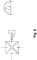
- the proximity sensor is the recognition of gestures using a 4-electrode system, the principle of which is shown in Figure 5 is illustrated in detail.
- the electrode system including the associated sensor electronics, should remain concentrated in the most compact possible form in a small space in order to be able to integrate it in a space-saving manner in existing facilities of various types. This also results in the further advantages of low-current operation with regard to battery applications and cost-effective implementation which have already been explained above.
- the task is to derive the x / y coordinates of a gesture movement with respect to the plane spanned by the electrodes from the information provided by the sensors.
- the x / y coordinates can be calculated in a simple manner independently of z.
- the distances r 1 to r 4 must be determined from the signals which are present at the output of the 4 sensors S1 to S4. Only the signal differences that arise when approaching the basic state are considered. These difference signals are denoted by e 1 to e 4 and are derived from the capacitance changes described above at the respective gates of the field effect transistors.
- the decisive factor here is the coupling capacity of the finger to the electrodes, which decreases with increasing distance from the electrode. Since the delivered amplitude of the signal difference according to the explanations from above is proportional to the change in capacitance, these values decrease with increasing distance.
- the constants e 0 , r 0 and a are dependent on the respective electrode shape and arrangement of the electrodes.
- FIG. 6 Various electrode arrangements are shown, which are either directly coupled to the electronics with short connections and thus form a compact unit that is only a few cm 2 in size, which can be easily integrated into other systems or can also be further away from the electronics by means of coaxial cables, for which purpose then preferably the cable shield is connected to the shielding output of the sensor (source connection of the FET) in order to keep the basic capacitance C1 at the gate connection low.
- a special measure in the circuit according to the invention lies in the particularly simple and thus energy and cost-saving implementation of the proximity sensor with a single FET stage and a downstream EXOR gate without the need for an additional comparator.
- the FET stage as far as it is switched as a source follower, provides an extremely low input capacitance and thus allows a high series resistance, which is decisive for the sensitivity, which is up to a factor of 50 higher than that of conventional sensors.
- the stage in this configuration also offers a shielding function, which can be used to keep the basic input capacitance low in critical installation situations and thus prevent a relevant loss of sensitivity.
- the concept according to the invention is characterized by a particularly low power consumption and is particularly suitable for battery applications.
- the costs, which are mainly determined by the number of active components of a circuit arrangement, and the space requirement are significantly less than in the case of conventional concepts.
- the circuit concept according to the invention is particularly advantageously suitable for systems with a simultaneous operation of several sensors, e.g. for gesture applications.
Landscapes
- Engineering & Computer Science (AREA)
- General Engineering & Computer Science (AREA)
- Theoretical Computer Science (AREA)
- Human Computer Interaction (AREA)
- Physics & Mathematics (AREA)
- General Physics & Mathematics (AREA)
- Electronic Switches (AREA)
- Measurement Of Length, Angles, Or The Like Using Electric Or Magnetic Means (AREA)
- Geophysics And Detection Of Objects (AREA)
Applications Claiming Priority (2)
| Application Number | Priority Date | Filing Date | Title |
|---|---|---|---|
| DE102008057823A DE102008057823A1 (de) | 2008-11-18 | 2008-11-18 | Kapazitives Sensorsystem |
| PCT/EP2009/008213 WO2010057625A1 (de) | 2008-11-18 | 2009-11-18 | Kapazitives sensorsystem |
Publications (2)
| Publication Number | Publication Date |
|---|---|
| EP2359476A1 EP2359476A1 (de) | 2011-08-24 |
| EP2359476B1 true EP2359476B1 (de) | 2020-05-20 |
Family
ID=41664676
Family Applications (1)
| Application Number | Title | Priority Date | Filing Date |
|---|---|---|---|
| EP09799244.0A Active EP2359476B1 (de) | 2008-11-18 | 2009-11-18 | Kapazitives sensorsystem |
Country Status (8)
Families Citing this family (24)
| Publication number | Priority date | Publication date | Assignee | Title |
|---|---|---|---|---|
| SE535106C2 (sv) * | 2010-07-09 | 2012-04-17 | Lars Aake Wern | En allmänt användbar kapacitiv sensor |
| US8599166B2 (en) * | 2010-08-27 | 2013-12-03 | Freescale Semiconductor, Inc. | Touch sensor controller for driving a touch sensor shield |
| JP5757118B2 (ja) * | 2011-03-23 | 2015-07-29 | ソニー株式会社 | 情報処理装置、情報処理方法及びプログラム |
| TWI459271B (zh) * | 2011-09-09 | 2014-11-01 | Generalplus Technology Inc | 觸控板的單、雙擊以及拖曳之判斷方法 |
| CN102749995B (zh) * | 2012-06-19 | 2015-11-04 | 上海华勤通讯技术有限公司 | 移动终端及移动终端挥控方法 |
| DK2731356T3 (en) * | 2012-11-07 | 2016-05-09 | Oticon As | Body worn control device for hearing aids |
| KR101472001B1 (ko) * | 2012-12-06 | 2014-12-15 | 이성호 | Ac 전원에 연동한 커패시턴스 검출 수단 및 방법 |
| JP6174435B2 (ja) * | 2013-09-25 | 2017-08-02 | 富士通コンポーネント株式会社 | コンバイナ及び操作検出装置 |
| CN105004362B (zh) * | 2015-06-27 | 2017-06-13 | 华东光电集成器件研究所 | 一种电容式传感器静电力驱动装置 |
| US11692853B2 (en) * | 2016-01-06 | 2023-07-04 | Disruptive Technologies Research As | Ultra low power source follower for capacitive sensor shield drivers |
| DE102016102392A1 (de) * | 2016-02-11 | 2017-08-17 | Valeo Schalter Und Sensoren Gmbh | Bedienvorrichtung für ein Kraftfahrzeug mit kapazitiver Annäherungssensorik sowie Kraftfahrzeug |
| US10146371B2 (en) * | 2016-03-29 | 2018-12-04 | Microchip Technology Incorporated | Water robustness and detection on capacitive buttons |
| JP6722498B2 (ja) * | 2016-04-21 | 2020-07-15 | 株式会社アルファ | 人体検知装置 |
| US10754465B2 (en) * | 2017-02-15 | 2020-08-25 | Sharp Kabushiki Kaisha | Display device |
| JP7052308B2 (ja) * | 2017-11-15 | 2022-04-12 | セイコーエプソン株式会社 | センサー、およびロボット |
| CN108195490B (zh) * | 2018-01-31 | 2019-10-11 | 北京他山科技有限公司 | 具有分时、分区域屏蔽功能的传感器、电子皮肤和机器人 |
| CN110463041B (zh) * | 2018-03-06 | 2023-08-25 | 深圳市汇顶科技股份有限公司 | 用于电容检测的电路、触摸检测装置和终端设备 |
| DE102018106620A1 (de) * | 2018-03-21 | 2019-09-26 | Huf Hülsbeck & Fürst Gmbh & Co. Kg | Kapazitive Sensorvorrichtung eines Fahrzeuges |
| KR102001885B1 (ko) * | 2018-12-18 | 2019-07-19 | 코어다 주식회사 | 모션 인식을 이용한 보안 기기의 작동 방법 및 보안 기기의 작동 프로그램 |
| DE102019200299A1 (de) * | 2019-01-11 | 2020-07-16 | Robert Bosch Gmbh | Kapazitives Sensorsystem |
| US11196412B1 (en) * | 2020-01-02 | 2021-12-07 | Xilinx, Inc. | Technique to improve bandwidth and high frequency return loss for push-pull buffer architecture |
| FR3107129B1 (fr) * | 2020-02-10 | 2022-02-18 | St Microelectronics Sa | Dispositif et méthode de détection d’un contact tactile |
| LU504509B1 (en) * | 2023-06-15 | 2024-12-16 | Luxembourg Inst Science & Tech List | Human-machine interface with transparent capacitive sensing surface |
| LU504508B1 (en) * | 2023-06-15 | 2024-12-16 | Luxembourg Inst Science & Tech List | Human-machine interface for contactless entry of commands by gestures |
Family Cites Families (45)
| Publication number | Priority date | Publication date | Assignee | Title |
|---|---|---|---|---|
| US3828256A (en) * | 1971-05-13 | 1974-08-06 | C Liu | Self contained test probe employing high input impedance |
| US4290052A (en) * | 1979-10-26 | 1981-09-15 | General Electric Company | Capacitive touch entry apparatus having high degree of personal safety |
| US4789822A (en) | 1984-07-18 | 1988-12-06 | Naoyuki Ohmatoi | Three-electrode sensor for phase comparison and pulse phase adjusting circuit for use with the sensor |
| US4939382A (en) * | 1989-04-20 | 1990-07-03 | Victor Gruodis | Touch responsive power control system |
| JP2733300B2 (ja) * | 1989-04-28 | 1998-03-30 | 松下電器産業株式会社 | キー入力装置 |
| US5012124A (en) * | 1989-07-24 | 1991-04-30 | Hollaway Jerrell P | Touch sensitive control panel |
| JPH05291928A (ja) | 1992-04-09 | 1993-11-05 | Navitas Kk | タッチスイッチ回路 |
| US5943516A (en) * | 1994-01-31 | 1999-08-24 | Fuji Photo Film Co., Ltd. | Camera with a warning system of inappropriate camera holding |
| US5508700A (en) * | 1994-03-17 | 1996-04-16 | Tanisys Technology, Inc. | Capacitance sensitive switch and switch array |
| US5801340A (en) | 1995-06-29 | 1998-09-01 | Invotronics Manufacturing | Proximity sensor |
| DE69700422T2 (de) * | 1996-04-15 | 2000-03-02 | Pressenk Instr Inc | Berührungssensor ohne Kissen |
| WO1998007051A1 (en) | 1996-08-14 | 1998-02-19 | Breed Automotive Technology, Inc. | Phase shift detection and measurement circuit for capacitive sensor |
| WO1998026506A1 (en) | 1996-12-10 | 1998-06-18 | Caldwell David W | Differential touch sensors and control circuit therefor |
| JPH10206169A (ja) | 1997-01-23 | 1998-08-07 | Murata Mfg Co Ltd | 静電容量型外力検出装置 |
| EP1717679B1 (en) * | 1998-01-26 | 2016-09-21 | Apple Inc. | Method for integrating manual input |
| JP3237629B2 (ja) * | 1998-10-27 | 2001-12-10 | ぺんてる株式会社 | 直接触式タッチパネル装置 |
| DE60032286T8 (de) * | 1999-06-10 | 2007-09-27 | Nippon Telegraph And Telephone Corp. | Gerät zur Erkennung von Oberflächengestalten |
| DE10005173A1 (de) * | 2000-02-05 | 2001-08-09 | Ego Elektro Geraetebau Gmbh | Schaltungsanordnung für ein Sensorelement |
| KR100346266B1 (ko) * | 2000-06-01 | 2002-07-26 | 엘지전자주식회사 | 평판형 발광소자를 백라이트로 이용한 터치 스위치 장치 |
| KR100366503B1 (ko) * | 2000-06-13 | 2003-01-09 | 주식회사 엘지이아이 | 글래스 터치 감지회로 |
| WO2002063320A1 (en) * | 2001-02-02 | 2002-08-15 | Haase Wayne C | Digital measurement circuit and system using a grounded capacitive sensor |
| US6657616B2 (en) * | 2001-03-16 | 2003-12-02 | Invensys Appliance Controls Company | Capacitive touch keyboard |
| WO2004040538A1 (en) * | 2002-10-28 | 2004-05-13 | Semtech Corporation | Data acquisition from capacitive touch pad |
| EP1556669A1 (en) * | 2002-10-31 | 2005-07-27 | Harald Philipp | Charge transfer capacitive position sensor |
| CN1287522C (zh) * | 2002-12-20 | 2006-11-29 | 阿尔卑斯电气株式会社 | 具有静电传感器的输入装置 |
| US20040239535A1 (en) * | 2003-05-29 | 2004-12-02 | Lancer Partnership, Ltd. | Self-calibrating dielectric property-based switch |
| JP3693665B2 (ja) * | 2003-08-06 | 2005-09-07 | 東京エレクトロン株式会社 | 容量検出回路及び容量検出方法 |
| KR100983524B1 (ko) * | 2003-12-01 | 2010-09-24 | 삼성전자주식회사 | 광감지 패널과, 이를 갖는 광감지 장치 및 이의 구동 방법 |
| TWI272539B (en) * | 2004-06-03 | 2007-02-01 | Atlab Inc | Electrical touch sensor and human interface device using the same |
| KR100642497B1 (ko) * | 2004-06-03 | 2006-11-02 | 주식회사 애트랩 | 전기적 접촉센서 |
| JP4531469B2 (ja) | 2004-07-15 | 2010-08-25 | 株式会社フジクラ | 静電容量式近接センサ |
| JP4082402B2 (ja) | 2004-10-19 | 2008-04-30 | 松下電器産業株式会社 | タッチキーを用いた電磁調理器 |
| DE102005014933A1 (de) * | 2004-12-17 | 2006-07-06 | Diehl Ako Stiftung & Co. Kg | Schaltungsanordnung für einen kapazitiven Berührungsschalter |
| US9298311B2 (en) * | 2005-06-23 | 2016-03-29 | Apple Inc. | Trackpad sensitivity compensation |
| JP2007018839A (ja) * | 2005-07-07 | 2007-01-25 | Fujikura Ltd | 静電容量式近接センサ |
| KR100552451B1 (ko) * | 2005-07-27 | 2006-02-21 | 실리콘 디스플레이 (주) | 문턱전압이 보상되는 요철 검출장치 및 그 방법 |
| DE102005041113A1 (de) * | 2005-08-30 | 2007-03-01 | BSH Bosch und Siemens Hausgeräte GmbH | Kapazitiver Annäherungsschalter und Haushaltsgerät mit einem solchen |
| DE102005041112A1 (de) * | 2005-08-30 | 2007-03-01 | BSH Bosch und Siemens Hausgeräte GmbH | Kapazitiver Annäherungsschalter und Haushaltgerät mit einem solchen |
| DE102006005581B4 (de) * | 2006-02-06 | 2007-10-04 | Diehl Ako Stiftung & Co. Kg | Kapazitiver Berührungsschalter |
| JP2008017432A (ja) | 2006-06-30 | 2008-01-24 | Nissei Giken Kk | タッチセンサ |
| WO2008070454A2 (en) * | 2006-11-28 | 2008-06-12 | Process Equipment Co. Of Tipp City | Proximity detection system |
| US7986313B2 (en) * | 2007-01-03 | 2011-07-26 | Apple Inc. | Analog boundary scanning based on stray capacitance |
| JP5064848B2 (ja) * | 2007-03-14 | 2012-10-31 | アルプス電気株式会社 | 静電容量スイッチ |
| US8059103B2 (en) * | 2007-11-21 | 2011-11-15 | 3M Innovative Properties Company | System and method for determining touch positions based on position-dependent electrical charges |
| US9927924B2 (en) * | 2008-09-26 | 2018-03-27 | Apple Inc. | Differential sensing for a touch panel |
-
2008
- 2008-11-18 DE DE102008057823A patent/DE102008057823A1/de not_active Withdrawn
-
2009
- 2009-11-18 KR KR1020117014031A patent/KR101772919B1/ko not_active Expired - Fee Related
- 2009-11-18 EP EP09799244.0A patent/EP2359476B1/de active Active
- 2009-11-18 CN CN200980154103.0A patent/CN102273075B/zh not_active Expired - Fee Related
- 2009-11-18 US US12/743,676 patent/US10003334B2/en active Active
- 2009-11-18 TW TW098139085A patent/TWI530097B/zh not_active IP Right Cessation
- 2009-11-18 JP JP2011535931A patent/JP5529881B2/ja not_active Expired - Fee Related
- 2009-11-18 DE DE112009004269T patent/DE112009004269A5/de not_active Withdrawn
- 2009-11-18 WO PCT/EP2009/008213 patent/WO2010057625A1/de active Application Filing
Non-Patent Citations (1)
| Title |
|---|
| None * |
Also Published As
| Publication number | Publication date |
|---|---|
| KR20110097851A (ko) | 2011-08-31 |
| DE112009004269A5 (de) | 2013-01-03 |
| TWI530097B (zh) | 2016-04-11 |
| TW201032473A (en) | 2010-09-01 |
| JP2012509610A (ja) | 2012-04-19 |
| CN102273075B (zh) | 2015-12-02 |
| EP2359476A1 (de) | 2011-08-24 |
| US10003334B2 (en) | 2018-06-19 |
| JP5529881B2 (ja) | 2014-06-25 |
| CN102273075A (zh) | 2011-12-07 |
| KR101772919B1 (ko) | 2017-08-30 |
| DE102008057823A1 (de) | 2010-08-19 |
| US20110304576A1 (en) | 2011-12-15 |
| WO2010057625A1 (de) | 2010-05-27 |
Similar Documents
| Publication | Publication Date | Title |
|---|---|---|
| EP2359476B1 (de) | Kapazitives sensorsystem | |
| EP2798740B1 (de) | Kapazitive sensoreinrichtung mit zugehöriger auswerteschaltung | |
| EP3329597B1 (de) | Bedieneinrichtung für ein fahrzeug und verfahren zum betrieb einer solchen bedieneinrichtung | |
| DE112016000716T5 (de) | Kapazitive Fingerabdruck-Erfassungsvorrichtung mit Stromauslesung aus Erfassungselementen | |
| DE112015005726T5 (de) | Kapazitive Fingerabdruck-Erfassungsvorrichtung mit Demodulationsschaltungsaufbau im Erfassungselement | |
| DE202010018476U1 (de) | Kapazitiver berührungsempfindlicher Bildschirm | |
| DE102014117823A1 (de) | Lenkrad für ein Kraftfahrzeug mit einem Sensorsystem und Verfahren zum Erkennen einer Anwesenheit einer menschlichen Hand in einem Greifbereich eines solchen Lenkrads | |
| DE102010007768A1 (de) | System und Verfahren zur Kapazitätswertbestimmung | |
| DE102014107927A1 (de) | Verfahren und Vorrichtung zur Überwachung des Füllstandes eines Mediums in einem Behälter | |
| DE102019120136A1 (de) | Kapazitive Sensorvorrichtung, Lenkrad mit einer kapazitiven Sensorvorrichtung, Verfahren zum Betrieb einer kapazitiven Sensorvorrichtung und/oder eines Lenkrads sowie Fahrzeug mit einer kapazitiven Sensorvorrichtung | |
| DE10121008B4 (de) | Kapazitive Tastatur mit Auswerteschaltung | |
| DE102011078369B4 (de) | Kapazitive Sensoreinrichtung sowie Verfahren zum Kalibrieren einer kapazitiven Sensoreinrichtung | |
| DE102019133928A1 (de) | Anordnung für ein Fahrzeug | |
| DE102019133913A1 (de) | Anordnung für ein Fahrzeug | |
| EP3474452B1 (de) | Verfahren zum auswerten eines kapazitätswerts einer kapazitiven sensorelektrode | |
| DE102010049962B4 (de) | Sensoranordnung und Verfahren zum Betreiben einer Sensoranordnung | |
| DE112021002654T5 (de) | Kapazitätserfassungsvorrichtung und eingabevorrichtung | |
| DE102011056226A1 (de) | Sensorsystem sowie Verfahren zur Reduktion einer Einschwingzeit eines Sensorsystems | |
| EP3829065A1 (de) | Kapazitive sensoreinrichtung sowie verfahren zur erkennung einer objektannäherung | |
| DE102013221346B4 (de) | Front-Schaltung für einen kapazitiven Sensor | |
| DE102014113545A1 (de) | Vorrichtung und Verfahren zur Überwachung einer Prozessgröße eines Mediums | |
| EP2529483B1 (de) | Schaltungsanordnung zum bestimmen einer kapazität einer anzahl von kapazitiven sensorelementen | |
| DE102016001865A1 (de) | Detektionsschaltung, elektrostatische Halteeinrichtung und Verfahren zur Erfassung eines Bauteils an einer elektrostatischen Halteeinrichtung | |
| DE102015119969A1 (de) | Anordung zum Betrieb und/oder zur Messung der Erzeugerleistung eines kapazitiven Energie-Harvesters | |
| WO2020002594A1 (de) | Kapazitives sensorsystem zur berührungserkennung |
Legal Events
| Date | Code | Title | Description |
|---|---|---|---|
| PUAI | Public reference made under article 153(3) epc to a published international application that has entered the european phase |
Free format text: ORIGINAL CODE: 0009012 |
|
| 17P | Request for examination filed |
Effective date: 20110620 |
|
| AK | Designated contracting states |
Kind code of ref document: A1 Designated state(s): AT BE BG CH CY CZ DE DK EE ES FI FR GB GR HR HU IE IS IT LI LT LU LV MC MK MT NL NO PL PT RO SE SI SK SM TR |
|
| RAP1 | Party data changed (applicant data changed or rights of an application transferred) |
Owner name: IDENT TECHNOLOGY AG |
|
| DAX | Request for extension of the european patent (deleted) | ||
| STAA | Information on the status of an ep patent application or granted ep patent |
Free format text: STATUS: EXAMINATION IS IN PROGRESS |
|
| 17Q | First examination report despatched |
Effective date: 20181217 |
|
| RAP1 | Party data changed (applicant data changed or rights of an application transferred) |
Owner name: MICROCHIP TECHNOLOGY GERMANY GMBH |
|
| GRAP | Despatch of communication of intention to grant a patent |
Free format text: ORIGINAL CODE: EPIDOSNIGR1 |
|
| STAA | Information on the status of an ep patent application or granted ep patent |
Free format text: STATUS: GRANT OF PATENT IS INTENDED |
|
| INTG | Intention to grant announced |
Effective date: 20191213 |
|
| GRAS | Grant fee paid |
Free format text: ORIGINAL CODE: EPIDOSNIGR3 |
|
| GRAA | (expected) grant |
Free format text: ORIGINAL CODE: 0009210 |
|
| STAA | Information on the status of an ep patent application or granted ep patent |
Free format text: STATUS: THE PATENT HAS BEEN GRANTED |
|
| AK | Designated contracting states |
Kind code of ref document: B1 Designated state(s): AT BE BG CH CY CZ DE DK EE ES FI FR GB GR HR HU IE IS IT LI LT LU LV MC MK MT NL NO PL PT RO SE SI SK SM TR |
|
| REG | Reference to a national code |
Ref country code: GB Ref legal event code: FG4D Free format text: NOT ENGLISH |
|
| REG | Reference to a national code |
Ref country code: CH Ref legal event code: EP |
|
| REG | Reference to a national code |
Ref country code: DE Ref legal event code: R096 Ref document number: 502009016199 Country of ref document: DE |
|
| REG | Reference to a national code |
Ref country code: AT Ref legal event code: REF Ref document number: 1273285 Country of ref document: AT Kind code of ref document: T Effective date: 20200615 |
|
| REG | Reference to a national code |
Ref country code: LT Ref legal event code: MG4D |
|
| REG | Reference to a national code |
Ref country code: NL Ref legal event code: MP Effective date: 20200520 |
|
| PG25 | Lapsed in a contracting state [announced via postgrant information from national office to epo] |
Ref country code: PT Free format text: LAPSE BECAUSE OF FAILURE TO SUBMIT A TRANSLATION OF THE DESCRIPTION OR TO PAY THE FEE WITHIN THE PRESCRIBED TIME-LIMIT Effective date: 20200921 Ref country code: FI Free format text: LAPSE BECAUSE OF FAILURE TO SUBMIT A TRANSLATION OF THE DESCRIPTION OR TO PAY THE FEE WITHIN THE PRESCRIBED TIME-LIMIT Effective date: 20200520 Ref country code: GR Free format text: LAPSE BECAUSE OF FAILURE TO SUBMIT A TRANSLATION OF THE DESCRIPTION OR TO PAY THE FEE WITHIN THE PRESCRIBED TIME-LIMIT Effective date: 20200821 Ref country code: IS Free format text: LAPSE BECAUSE OF FAILURE TO SUBMIT A TRANSLATION OF THE DESCRIPTION OR TO PAY THE FEE WITHIN THE PRESCRIBED TIME-LIMIT Effective date: 20200920 Ref country code: NO Free format text: LAPSE BECAUSE OF FAILURE TO SUBMIT A TRANSLATION OF THE DESCRIPTION OR TO PAY THE FEE WITHIN THE PRESCRIBED TIME-LIMIT Effective date: 20200820 Ref country code: SE Free format text: LAPSE BECAUSE OF FAILURE TO SUBMIT A TRANSLATION OF THE DESCRIPTION OR TO PAY THE FEE WITHIN THE PRESCRIBED TIME-LIMIT Effective date: 20200520 Ref country code: LT Free format text: LAPSE BECAUSE OF FAILURE TO SUBMIT A TRANSLATION OF THE DESCRIPTION OR TO PAY THE FEE WITHIN THE PRESCRIBED TIME-LIMIT Effective date: 20200520 |
|
| PG25 | Lapsed in a contracting state [announced via postgrant information from national office to epo] |
Ref country code: BG Free format text: LAPSE BECAUSE OF FAILURE TO SUBMIT A TRANSLATION OF THE DESCRIPTION OR TO PAY THE FEE WITHIN THE PRESCRIBED TIME-LIMIT Effective date: 20200820 Ref country code: LV Free format text: LAPSE BECAUSE OF FAILURE TO SUBMIT A TRANSLATION OF THE DESCRIPTION OR TO PAY THE FEE WITHIN THE PRESCRIBED TIME-LIMIT Effective date: 20200520 Ref country code: HR Free format text: LAPSE BECAUSE OF FAILURE TO SUBMIT A TRANSLATION OF THE DESCRIPTION OR TO PAY THE FEE WITHIN THE PRESCRIBED TIME-LIMIT Effective date: 20200520 |
|
| PG25 | Lapsed in a contracting state [announced via postgrant information from national office to epo] |
Ref country code: NL Free format text: LAPSE BECAUSE OF FAILURE TO SUBMIT A TRANSLATION OF THE DESCRIPTION OR TO PAY THE FEE WITHIN THE PRESCRIBED TIME-LIMIT Effective date: 20200520 |
|
| PG25 | Lapsed in a contracting state [announced via postgrant information from national office to epo] |
Ref country code: SM Free format text: LAPSE BECAUSE OF FAILURE TO SUBMIT A TRANSLATION OF THE DESCRIPTION OR TO PAY THE FEE WITHIN THE PRESCRIBED TIME-LIMIT Effective date: 20200520 Ref country code: EE Free format text: LAPSE BECAUSE OF FAILURE TO SUBMIT A TRANSLATION OF THE DESCRIPTION OR TO PAY THE FEE WITHIN THE PRESCRIBED TIME-LIMIT Effective date: 20200520 Ref country code: DK Free format text: LAPSE BECAUSE OF FAILURE TO SUBMIT A TRANSLATION OF THE DESCRIPTION OR TO PAY THE FEE WITHIN THE PRESCRIBED TIME-LIMIT Effective date: 20200520 Ref country code: IT Free format text: LAPSE BECAUSE OF FAILURE TO SUBMIT A TRANSLATION OF THE DESCRIPTION OR TO PAY THE FEE WITHIN THE PRESCRIBED TIME-LIMIT Effective date: 20200520 Ref country code: RO Free format text: LAPSE BECAUSE OF FAILURE TO SUBMIT A TRANSLATION OF THE DESCRIPTION OR TO PAY THE FEE WITHIN THE PRESCRIBED TIME-LIMIT Effective date: 20200520 Ref country code: CZ Free format text: LAPSE BECAUSE OF FAILURE TO SUBMIT A TRANSLATION OF THE DESCRIPTION OR TO PAY THE FEE WITHIN THE PRESCRIBED TIME-LIMIT Effective date: 20200520 Ref country code: ES Free format text: LAPSE BECAUSE OF FAILURE TO SUBMIT A TRANSLATION OF THE DESCRIPTION OR TO PAY THE FEE WITHIN THE PRESCRIBED TIME-LIMIT Effective date: 20200520 |
|
| REG | Reference to a national code |
Ref country code: DE Ref legal event code: R097 Ref document number: 502009016199 Country of ref document: DE |
|
| PG25 | Lapsed in a contracting state [announced via postgrant information from national office to epo] |
Ref country code: PL Free format text: LAPSE BECAUSE OF FAILURE TO SUBMIT A TRANSLATION OF THE DESCRIPTION OR TO PAY THE FEE WITHIN THE PRESCRIBED TIME-LIMIT Effective date: 20200520 Ref country code: SK Free format text: LAPSE BECAUSE OF FAILURE TO SUBMIT A TRANSLATION OF THE DESCRIPTION OR TO PAY THE FEE WITHIN THE PRESCRIBED TIME-LIMIT Effective date: 20200520 |
|
| PLBE | No opposition filed within time limit |
Free format text: ORIGINAL CODE: 0009261 |
|
| STAA | Information on the status of an ep patent application or granted ep patent |
Free format text: STATUS: NO OPPOSITION FILED WITHIN TIME LIMIT |
|
| 26N | No opposition filed |
Effective date: 20210223 |
|
| PG25 | Lapsed in a contracting state [announced via postgrant information from national office to epo] |
Ref country code: SI Free format text: LAPSE BECAUSE OF FAILURE TO SUBMIT A TRANSLATION OF THE DESCRIPTION OR TO PAY THE FEE WITHIN THE PRESCRIBED TIME-LIMIT Effective date: 20200520 |
|
| PG25 | Lapsed in a contracting state [announced via postgrant information from national office to epo] |
Ref country code: MC Free format text: LAPSE BECAUSE OF FAILURE TO SUBMIT A TRANSLATION OF THE DESCRIPTION OR TO PAY THE FEE WITHIN THE PRESCRIBED TIME-LIMIT Effective date: 20200520 |
|
| REG | Reference to a national code |
Ref country code: CH Ref legal event code: PL |
|
| GBPC | Gb: european patent ceased through non-payment of renewal fee |
Effective date: 20201118 |
|
| PG25 | Lapsed in a contracting state [announced via postgrant information from national office to epo] |
Ref country code: LU Free format text: LAPSE BECAUSE OF NON-PAYMENT OF DUE FEES Effective date: 20201118 |
|
| REG | Reference to a national code |
Ref country code: BE Ref legal event code: MM Effective date: 20201130 |
|
| PG25 | Lapsed in a contracting state [announced via postgrant information from national office to epo] |
Ref country code: CH Free format text: LAPSE BECAUSE OF NON-PAYMENT OF DUE FEES Effective date: 20201130 Ref country code: LI Free format text: LAPSE BECAUSE OF NON-PAYMENT OF DUE FEES Effective date: 20201130 |
|
| PG25 | Lapsed in a contracting state [announced via postgrant information from national office to epo] |
Ref country code: FR Free format text: LAPSE BECAUSE OF NON-PAYMENT OF DUE FEES Effective date: 20201130 Ref country code: IE Free format text: LAPSE BECAUSE OF NON-PAYMENT OF DUE FEES Effective date: 20201118 |
|
| PG25 | Lapsed in a contracting state [announced via postgrant information from national office to epo] |
Ref country code: GB Free format text: LAPSE BECAUSE OF NON-PAYMENT OF DUE FEES Effective date: 20201118 |
|
| REG | Reference to a national code |
Ref country code: AT Ref legal event code: MM01 Ref document number: 1273285 Country of ref document: AT Kind code of ref document: T Effective date: 20201118 |
|
| PG25 | Lapsed in a contracting state [announced via postgrant information from national office to epo] |
Ref country code: AT Free format text: LAPSE BECAUSE OF NON-PAYMENT OF DUE FEES Effective date: 20201118 |
|
| PGFP | Annual fee paid to national office [announced via postgrant information from national office to epo] |
Ref country code: DE Payment date: 20211020 Year of fee payment: 13 |
|
| PG25 | Lapsed in a contracting state [announced via postgrant information from national office to epo] |
Ref country code: TR Free format text: LAPSE BECAUSE OF FAILURE TO SUBMIT A TRANSLATION OF THE DESCRIPTION OR TO PAY THE FEE WITHIN THE PRESCRIBED TIME-LIMIT Effective date: 20200520 Ref country code: MT Free format text: LAPSE BECAUSE OF FAILURE TO SUBMIT A TRANSLATION OF THE DESCRIPTION OR TO PAY THE FEE WITHIN THE PRESCRIBED TIME-LIMIT Effective date: 20200520 Ref country code: CY Free format text: LAPSE BECAUSE OF FAILURE TO SUBMIT A TRANSLATION OF THE DESCRIPTION OR TO PAY THE FEE WITHIN THE PRESCRIBED TIME-LIMIT Effective date: 20200520 |
|
| PG25 | Lapsed in a contracting state [announced via postgrant information from national office to epo] |
Ref country code: MK Free format text: LAPSE BECAUSE OF FAILURE TO SUBMIT A TRANSLATION OF THE DESCRIPTION OR TO PAY THE FEE WITHIN THE PRESCRIBED TIME-LIMIT Effective date: 20200520 |
|
| PG25 | Lapsed in a contracting state [announced via postgrant information from national office to epo] |
Ref country code: BE Free format text: LAPSE BECAUSE OF NON-PAYMENT OF DUE FEES Effective date: 20201130 |
|
| REG | Reference to a national code |
Ref country code: DE Ref legal event code: R119 Ref document number: 502009016199 Country of ref document: DE |
|
| PG25 | Lapsed in a contracting state [announced via postgrant information from national office to epo] |
Ref country code: DE Free format text: LAPSE BECAUSE OF NON-PAYMENT OF DUE FEES Effective date: 20230601 |