EP2358467B1 - Mischer - Google Patents
Mischer Download PDFInfo
- Publication number
- EP2358467B1 EP2358467B1 EP09764834.9A EP09764834A EP2358467B1 EP 2358467 B1 EP2358467 B1 EP 2358467B1 EP 09764834 A EP09764834 A EP 09764834A EP 2358467 B1 EP2358467 B1 EP 2358467B1
- Authority
- EP
- European Patent Office
- Prior art keywords
- tool
- motor
- shaft
- mixer
- housing
- Prior art date
- Legal status (The legal status is an assumption and is not a legal conclusion. Google has not performed a legal analysis and makes no representation as to the accuracy of the status listed.)
- Active
Links
- 230000001360 synchronised effect Effects 0.000 claims description 2
- 230000005540 biological transmission Effects 0.000 description 2
- 238000006243 chemical reaction Methods 0.000 description 1
- 230000010354 integration Effects 0.000 description 1
- 239000007788 liquid Substances 0.000 description 1
- 238000012423 maintenance Methods 0.000 description 1
- 238000004519 manufacturing process Methods 0.000 description 1
- 239000000463 material Substances 0.000 description 1
Images
Classifications
-
- B—PERFORMING OPERATIONS; TRANSPORTING
- B01—PHYSICAL OR CHEMICAL PROCESSES OR APPARATUS IN GENERAL
- B01F—MIXING, e.g. DISSOLVING, EMULSIFYING OR DISPERSING
- B01F29/00—Mixers with rotating receptacles
- B01F29/80—Mixers with rotating receptacles rotating about a substantially vertical axis
- B01F29/83—Mixers with rotating receptacles rotating about a substantially vertical axis with rotary paddles or arms, e.g. movable out of the receptacle
-
- B—PERFORMING OPERATIONS; TRANSPORTING
- B01—PHYSICAL OR CHEMICAL PROCESSES OR APPARATUS IN GENERAL
- B01F—MIXING, e.g. DISSOLVING, EMULSIFYING OR DISPERSING
- B01F29/00—Mixers with rotating receptacles
- B01F29/60—Mixers with rotating receptacles rotating about a horizontal or inclined axis, e.g. drum mixers
- B01F29/64—Mixers with rotating receptacles rotating about a horizontal or inclined axis, e.g. drum mixers with stirring devices moving in relation to the receptacle, e.g. rotating
-
- B—PERFORMING OPERATIONS; TRANSPORTING
- B01—PHYSICAL OR CHEMICAL PROCESSES OR APPARATUS IN GENERAL
- B01F—MIXING, e.g. DISSOLVING, EMULSIFYING OR DISPERSING
- B01F35/00—Accessories for mixers; Auxiliary operations or auxiliary devices; Parts or details of general application
-
- B—PERFORMING OPERATIONS; TRANSPORTING
- B01—PHYSICAL OR CHEMICAL PROCESSES OR APPARATUS IN GENERAL
- B01F—MIXING, e.g. DISSOLVING, EMULSIFYING OR DISPERSING
- B01F35/00—Accessories for mixers; Auxiliary operations or auxiliary devices; Parts or details of general application
- B01F35/30—Driving arrangements; Transmissions; Couplings; Brakes
- B01F35/32—Driving arrangements
- B01F35/321—Disposition of the drive
- B01F35/3212—Disposition of the drive mounted on the receptacle
-
- B—PERFORMING OPERATIONS; TRANSPORTING
- B01—PHYSICAL OR CHEMICAL PROCESSES OR APPARATUS IN GENERAL
- B01F—MIXING, e.g. DISSOLVING, EMULSIFYING OR DISPERSING
- B01F35/00—Accessories for mixers; Auxiliary operations or auxiliary devices; Parts or details of general application
- B01F35/30—Driving arrangements; Transmissions; Couplings; Brakes
- B01F35/32—Driving arrangements
- B01F35/321—Disposition of the drive
- B01F35/3214—Disposition of the drive at the upper side of the axis, e.g. driving the stirrer from the top of a receptacle
-
- B—PERFORMING OPERATIONS; TRANSPORTING
- B22—CASTING; POWDER METALLURGY
- B22C—FOUNDRY MOULDING
- B22C5/00—Machines or devices specially designed for dressing or handling the mould material so far as specially adapted for that purpose
- B22C5/04—Machines or devices specially designed for dressing or handling the mould material so far as specially adapted for that purpose by grinding, blending, mixing, kneading, or stirring
- B22C5/0409—Blending, mixing, kneading or stirring; Methods therefor
- B22C5/0454—Blending, mixing, kneading or stirring; Methods therefor with bottom disc rotating about a vertical axis or with receptacle rotating about a vertical or steeply inclined axis, e.g. with fixed or driven tools, such as rolls
-
- B—PERFORMING OPERATIONS; TRANSPORTING
- B01—PHYSICAL OR CHEMICAL PROCESSES OR APPARATUS IN GENERAL
- B01F—MIXING, e.g. DISSOLVING, EMULSIFYING OR DISPERSING
- B01F35/00—Accessories for mixers; Auxiliary operations or auxiliary devices; Parts or details of general application
- B01F35/30—Driving arrangements; Transmissions; Couplings; Brakes
- B01F2035/35—Use of other general mechanical engineering elements in mixing devices
- B01F2035/351—Sealings
Definitions
- the present invention relates to a mixer with a mixing container and a tool shaft arranged at least partially in the mixing container, wherein the tool shaft has a working end, to which a working tool is fastened or can be attached, and a drive end, which is mounted by means of two tool bearings spaced apart from each other, and wherein a drive motor is provided with a motor shaft for driving the tool shaft.
- Such a mixer is known, for example from the DE 35 20 409 A1 ,
- the embodiment shown there comprises a pressure-resistant mixer with a filling opening, a rotating mixing vessel having an emptying device, with mixing tools arranged eccentrically to the mixing vessel axis in the interior of the mixing vessel.
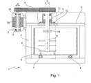
- FIG. 1 shows a vertical section through a mixer.
- the mixer 1 has a mixing container 3 accommodated in a mixer housing 2, which can be rotated about a vertical axis of rotation. To ensure this rotation of the mixing container 3 is rotatably mounted on a ball bearing 4.
- the mixing container may have on its underside an emptying opening (not shown in the figure).
- the mixer housing 2 has a housing cover 5. Inside the mixing container 3, a working tool 6 designed as a mixing tool is arranged inside the mixing container 3, a working tool 6 designed as a mixing tool is arranged. It can be seen that the working tool 6 about a vertical axis, which is spaced from the axis of rotation of the mixing container 3, is rotatable.
- a drive end of the working tool 6 is guided through the housing cover 5 and driven by means of the drive motor 7 via, for example, V-belt 9.
- the work tools 6 are fixed to a tool shaft 8, which has a drive end to which the V-belt 9 engages, and a working end to which the working tools 6 designed as a mixing tool are fastened.
- the tool shaft 8 is formed in two parts in the embodiment shown, wherein the two parts can be connected to each other via the flange 10 or separated from each other. This flange 10 is among other things there, the working tool 6 against another working tool 6, such. B. one Star vortex against a pin vortex swap.
- the work tool if it shows signs of wear, be replaced with a new one.
- both the mixing container 3 and the tool shaft 8 rotate, it can lead to significant lateral forces on the tool shaft 8, which are caused by the material flow through the rotating mixing container 3, especially since the tool shaft is held only on one side in the housing cover 5.
- the size of the shear force depends inter alia on the type of mix and of course on the rotational speed of both mixing container 3 and the working tool 6.
- two tool bearings 11, 12 are provided at the drive end, each bearing the shaft with a diameter D.
- the tool bearings 11, 12 are bolted to the mixer housing 2 or the housing cover 5 via a flange 13.
- the V-belt 9 then engages the drive end of the tool shaft 8.
- the drive motor 7 has a motor shaft 20, which is also held by two motor bearings 14, 15. It can be seen that the diameter d 'of the motor shaft 20 is significantly smaller than the diameter D of the tool shaft 8.
- the belt transmission consisting generally of a set of multiple V-belts or timing belt, a maintenance-intensive machine element. These components must be checked at regular intervals for correct voltage and this must be adjusted if necessary. Likewise, both V-belts and toothed belts are subject to wear and must therefore be replaced at regular intervals.
- the GB 330834 also shows a mixer with a mixing container and a mixing shaft arranged in the tool shaft to which a working tool is attached. This drive shaft is driven by a drive motor.
- the DE 197 12 324 C2 and the DE 39 42 679 A1 show mixing devices for mixing liquids.
- the motors of the mixing device are held by means of rotor bearings.
- this object is achieved by a mixer according to claim 1.
- one of the bearings which is provided for the storage of the tool shaft, simultaneously used for the storage of the motor shaft.
- Motor shaft and tool shaft are therefore directly connected.
- the motor is arranged between the two tool bearings and the motor shaft is preferably mounted by means of the two tool bearings.
- the motor shaft is preferably mounted by means of the two tool bearings.
- the bearings for the tool shaft also serve as a bearing for the motor shaft.
- no distinction can be made in this embodiment between engine and tool shaft, since a portion of the shaft acts as a motor shaft and another portion of the same shaft as a tool shaft.
- a direct drive preferably a direct drive and more preferably a three-phase synchronous motor (servo motor, torque motor, reluctance motor) is used.
- a three-phase synchronous motor servo motor, torque motor, reluctance motor
- the bearing of the motor shaft facing the tool shaft is suitable for absorbing particularly high radial and axial forces. It is a combined radial thrust bearing (Radiax bearing), e.g. designed as a spherical roller or self-aligning ball bearings and particularly preferably as a double-row spherical roller bearings.
- Radiax bearing radial thrust bearing
- a further preferred embodiment provides that the diameter of the motor shaft differs at the two tool bearings, wherein preferably the diameter of the motor shaft d "on the tool shaft facing away from the tool bearing smaller, preferably at least 30%, more preferably at least 50% smaller than the diameter of the motor shaft D at the other tool bearing.
- the motor is expediently arranged in a motor housing, wherein both tool bearings are arranged on or in the motor housing.
- the motor housing having a first outer flange, with which the motor housing and thus the motor is fixed to the mixer housing.
- the motor housing having a second outer flange which is also secured to the mixer housing, wherein the second outer flange preferably has a larger average diameter than the first outer flange.
- the motor housing could for example have a circular cross-section, in which case expediently also the outer flanges have a circular cross-section. In principle, however, other cross sections, such as square or rectangular cross-sections are conceivable. Characterized in that the second outer flange has a larger average diameter, the motor can be easily attached to the mixer housing.
- the mixer housing may include a through-stage opening having a first smaller diameter portion and a second larger diameter portion, the second portion having a mean diameter greater than the mean diameter of the first outer flange and smaller than the average diameter of the second Outside flange is.
- the smallest mean diameter of the passage stage opening in the mixer housing is greater than the largest outer diameter of the working tool. By this measure, the entire work tool including the engine can be removed via the passage step opening.
- both flanges have holes for attaching the flanges to the mixer housing.
- the larger flange may have additional openings, which are preferably larger than the holes for attachment, which are provided so that a tool can access through the opening to the holes or fasteners in the smaller flange. This facilitates the attachment of the motor housing to the mixer housing.
- the tool shaft consists of two parts detachably fastened to one another, wherein one part is connected in one piece with the motor shaft, while the other part carries the working tool.
- the detachable connection can be made via a flange connection.
- the tool shaft may also be formed integrally with the motor shaft.
- FIG. 1 shows an embodiment of the prior art, which has already been described above.
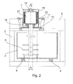
- FIG. 2 shows a first embodiment of the invention.
- the drive motor 7 is accommodated in a motor housing 16, the motor housing 16 being fastened to the mixer cover 5 by means of two outer flanges 13, 17.
- the tool shaft 8 simultaneously acts as a motor shaft 21 at its drive end.
- the motor shaft 21, which is partially formed in the embodiment shown as a hollow shaft is held by the spherical roller bearing 18 and the radial bearing 19.
- the second outer flange 13, which faces the product space, ie the mixing container more, has a smaller outer diameter than the first outer flange 17.
- the entire motor can be inserted from the outside into the housing cover 5, so that first the outer flange with the smaller Outer diameter is inserted into a corresponding stepped bore in the container lid until it rests on the bottom of the extended bore.
- the distance between the two outer flanges 13, 17 is dimensioned such that in the in FIG. 2 shown situation, both flanges can be screwed to the housing cover 5.
- the engine can be easily detached and removed from the container lid.
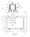
- FIG. 3 which simultaneously shows a second embodiment of the mixer according to the invention.
- the engine including working tool 6 has been released from the housing cover 5, so that the engine including working tool 6 can be removed from the corresponding opening in the container lid.
- the embodiment shown differs from that in FIG. 2 shown embodiment in that the flange 10 is missing, so that here tool shaft and motor shaft are integrally formed.
- the axis of rotation of the working tool is arranged eccentrically to the axis of rotation of the mixing container.
Landscapes
- Chemical & Material Sciences (AREA)
- Chemical Kinetics & Catalysis (AREA)
- Engineering & Computer Science (AREA)
- Mechanical Engineering (AREA)
- Accessories For Mixers (AREA)
- Mixers Of The Rotary Stirring Type (AREA)
- Food-Manufacturing Devices (AREA)
- Processing And Handling Of Plastics And Other Materials For Molding In General (AREA)
- Mixers With Rotating Receptacles And Mixers With Vibration Mechanisms (AREA)
Priority Applications (1)
| Application Number | Priority Date | Filing Date | Title |
|---|---|---|---|
| PL09764834T PL2358467T3 (pl) | 2008-12-17 | 2009-12-04 | Mieszalnik |
Applications Claiming Priority (2)
| Application Number | Priority Date | Filing Date | Title |
|---|---|---|---|
| DE102008054842A DE102008054842A1 (de) | 2008-12-17 | 2008-12-17 | Mischer |
| PCT/EP2009/066458 WO2010076120A1 (de) | 2008-12-17 | 2009-12-04 | Mischer mit drehbarem mischbehälter |
Publications (2)
| Publication Number | Publication Date |
|---|---|
| EP2358467A1 EP2358467A1 (de) | 2011-08-24 |
| EP2358467B1 true EP2358467B1 (de) | 2014-07-16 |
Family
ID=41666436
Family Applications (1)
| Application Number | Title | Priority Date | Filing Date |
|---|---|---|---|
| EP09764834.9A Active EP2358467B1 (de) | 2008-12-17 | 2009-12-04 | Mischer |
Country Status (20)
| Country | Link |
|---|---|
| US (1) | US9694331B2 (pt) |
| EP (1) | EP2358467B1 (pt) |
| JP (1) | JP5610163B2 (pt) |
| KR (1) | KR101665493B1 (pt) |
| CN (1) | CN102300629B (pt) |
| AU (1) | AU2009334941B2 (pt) |
| BR (1) | BRPI0923457B1 (pt) |
| CA (1) | CA2743256C (pt) |
| DE (1) | DE102008054842A1 (pt) |
| DK (1) | DK2358467T3 (pt) |
| ES (1) | ES2495747T3 (pt) |
| MX (1) | MX2011006161A (pt) |
| PE (1) | PE20120504A1 (pt) |
| PL (1) | PL2358467T3 (pt) |
| PT (1) | PT2358467E (pt) |
| RU (1) | RU2521571C2 (pt) |
| TW (1) | TWI523682B (pt) |
| UA (1) | UA105912C2 (pt) |
| WO (1) | WO2010076120A1 (pt) |
| ZA (1) | ZA201103278B (pt) |
Cited By (1)
| Publication number | Priority date | Publication date | Assignee | Title |
|---|---|---|---|---|
| US11684900B2 (en) | 2018-03-16 | 2023-06-27 | Maschinenfabrik Gustav Eirich Gmbh & Co. Kg | Hygienic mixer which is pivotably mounted |
Families Citing this family (26)
| Publication number | Priority date | Publication date | Assignee | Title |
|---|---|---|---|---|
| DE102010027885A1 (de) * | 2010-04-16 | 2012-02-09 | Maschinenfabrik Gustav Eirich Gmbh & Co. Kg | Mischvorrichtung mit Verschleißschutzauskleidung |
| CN102327755A (zh) * | 2010-07-12 | 2012-01-25 | 南通全技纺织涂层有限公司 | 用于织物涂层浆料的搅拌机 |
| US8845940B2 (en) | 2012-10-25 | 2014-09-30 | Carboncure Technologies Inc. | Carbon dioxide treatment of concrete upstream from product mold |
| CN102908929A (zh) * | 2012-11-18 | 2013-02-06 | 苏州蓝王机床工具科技有限公司 | 一种液态类物料搅拌机 |
| AU2014212083A1 (en) | 2013-02-04 | 2015-08-06 | Coldcrete, Inc. | System and method of applying carbon dioxide during the production of concrete |
| US9376345B2 (en) | 2013-06-25 | 2016-06-28 | Carboncure Technologies Inc. | Methods for delivery of carbon dioxide to a flowable concrete mix |
| US9388072B2 (en) | 2013-06-25 | 2016-07-12 | Carboncure Technologies Inc. | Methods and compositions for concrete production |
| US10927042B2 (en) | 2013-06-25 | 2021-02-23 | Carboncure Technologies, Inc. | Methods and compositions for concrete production |
| RU2534871C1 (ru) * | 2013-06-27 | 2014-12-10 | Федеральное государственное бюджетное образовательное учреждение высшего профессионального образования "Ярославский государственный технический университет" | Бетономешалка с импульсной стержневой мешалкой со свирелеобразными стержнями |
| WO2015123769A1 (en) | 2014-02-18 | 2015-08-27 | Carboncure Technologies, Inc. | Carbonation of cement mixes |
| WO2015154174A1 (en) | 2014-04-07 | 2015-10-15 | Carboncure Technologies, Inc. | Integrated carbon dioxide capture |
| DE102014117509A1 (de) * | 2014-11-28 | 2016-06-02 | Maschinenfabrik Gustav Eirich Gmbh & Co. Kg | Vorrichtung zur Aufbereitung und Kühlung von Gießereiformsand |
| JP6343683B2 (ja) * | 2015-01-19 | 2018-06-13 | 株式会社アルバック | 撹拌装置 |
| CN105170001B (zh) * | 2015-08-25 | 2017-09-15 | 晋江兴翼机械有限公司 | 组合式搅拌装置 |
| DE102016106536A1 (de) * | 2016-04-08 | 2017-10-12 | Maschinenfabrik Gustav Eirich Gmbh & Co. Kg | Mischwelle |
| AU2017249444B2 (en) | 2016-04-11 | 2022-08-18 | Carboncure Technologies Inc. | Methods and compositions for treatment of concrete wash water |
| CN106582394A (zh) * | 2016-12-09 | 2017-04-26 | 陈红 | 一种干电池生产工艺用原料密封混合设备 |
| US11958212B2 (en) | 2017-06-20 | 2024-04-16 | Carboncure Technologies Inc. | Methods and compositions for treatment of concrete wash water |
| DE102018106188A1 (de) * | 2018-03-16 | 2019-09-19 | Maschinenfabrik Gustav Eirich Gmbh & Co. Kg | Vorrichtung zur Umsetzung einer Linearbewegung in einem stationären System in eine Drehbewegung um eine Schwenkachse in einem sich um eine Drehachse drehenden System |
| DE102018106187A1 (de) * | 2018-03-16 | 2019-09-19 | Maschinenfabrik Gustav Eirich Gmbh & Co. Kg | Mischvorrichtung mit Verschlusselement |
| DE102018106184A1 (de) * | 2018-03-16 | 2019-09-19 | Maschinenfabrik Gustav Eirich Gmbh & Co. Kg | Mischvorrichtung mit Dichtung |
| DE102018106192A1 (de) | 2018-03-16 | 2019-09-19 | Maschinenfabrik Gustav Eirich Gmbh & Co. Kg | Mischvorrichtung mit zweiteiligem Verschlussdeckel |
| CN108854759A (zh) * | 2018-06-19 | 2018-11-23 | 广州高蒂丝生物科技有限公司 | 一种化妆品生产用高效原料混合装置 |
| CN108771988A (zh) * | 2018-06-21 | 2018-11-09 | 陈文� | 一种流体动态混合器 |
| EP3608015B1 (de) * | 2018-08-08 | 2021-10-06 | Harro Höfliger Verpackungsmaschinen GmbH | Pulverbereitstellungseinrichtung für einen pulverdosierer |
| CN114160753A (zh) * | 2021-11-26 | 2022-03-11 | 马鞍山市绿科环保科技有限公司 | 一种在铸造砂处理固体废弃物中分选原砂的方法 |
Citations (3)
| Publication number | Priority date | Publication date | Assignee | Title |
|---|---|---|---|---|
| DE3942679A1 (de) * | 1989-12-22 | 1991-06-27 | Ekato Ind Anlagen Verwalt | Mischvorrichtung |
| DE19712324C2 (de) * | 1997-03-24 | 2000-05-11 | Renner Gmbh | Umwälzpumpe oder Rührwerk für erwärmte chemische Lösungen |
| DE60015482T2 (de) * | 1999-12-24 | 2005-10-27 | Takashi Nishimoto | Verfahren und Vorrichtung zur Behandlung von kontaminierten Flüssigkeiten |
Family Cites Families (33)
| Publication number | Priority date | Publication date | Assignee | Title |
|---|---|---|---|---|
| US1435289A (en) * | 1918-01-28 | 1922-11-14 | Gilbert Co A C | Churn or agitator |
| US1351243A (en) * | 1919-02-21 | 1920-08-31 | French Battery & Carbon Co | Mixing-machine |
| US1718745A (en) * | 1927-06-01 | 1929-06-25 | Laing Lawrence | Mixer |
| US1783651A (en) * | 1929-07-15 | 1930-12-02 | Homer R Johnson | Kitchen utensil |
| GB330834A (en) | 1929-09-07 | 1930-06-19 | James Flynn Turner | Improvements in or relating to foundry sand mixer |
| US2008684A (en) * | 1931-10-27 | 1935-07-23 | Mixing Equipment Company Inc | Emulsifying unit |
| US1935857A (en) * | 1932-11-18 | 1933-11-21 | Nachumsohn Irving | Electric cream-whipper and drink mixer |
| US2250838A (en) * | 1939-12-19 | 1941-07-29 | Geneva Processes Inc | Mixing device |
| US3140861A (en) * | 1962-08-06 | 1964-07-14 | Donald E Krup | Mixing device |
| DE1301874B (de) | 1967-10-03 | 1969-08-28 | Ahrenberg Kurt | Befeuchtungsverfahren und -vorrichtung fuer Mischgueter, insbesondere Giessereiformsande |
| DE2323579C2 (de) | 1973-05-10 | 1975-03-06 | Gerd 5138 Heinsberg Meuser | Mischer für trockenes oder erdfeuchtes Mischgut z.B. Beton |
| US4159879A (en) * | 1976-03-18 | 1979-07-03 | Pioneer Associates #2 | Bread making machine |
| DE3520409A1 (de) | 1985-06-07 | 1986-12-11 | Hubert Eirich | Druckfester mischer |
| CN2055406U (zh) * | 1989-08-29 | 1990-04-04 | 冯连春 | 立式顺流搅拌机 |
| JP2900296B2 (ja) * | 1992-04-16 | 1999-06-02 | オルガノ株式会社 | 緩急撹拌槽 |
| RU2085275C1 (ru) * | 1993-07-29 | 1997-07-27 | Товарищество с ограниченной ответственностью Фирма "Диапазон" | Гидрокавитационный смеситель-диспергатор суспензии |
| US5813758A (en) * | 1993-12-10 | 1998-09-29 | Ahlstrom Machinery Inc. | Concentric ring fluidizing mixer |
| RU2083095C1 (ru) * | 1994-10-13 | 1997-07-10 | Юрий Ильич Деревцов | Маслобойка для сбивания масла из молочного сырья |
| DE19749223A1 (de) | 1997-11-07 | 1999-05-20 | Thomas Beindorf | Rührwerksvorrichtung |
| US6435262B1 (en) | 2001-03-16 | 2002-08-20 | New Ideas, Llc | Foundry sand |
| CN2541036Y (zh) * | 2002-03-05 | 2003-03-26 | 任荣泽 | 翻酱机 |
| US6685358B2 (en) | 2002-04-29 | 2004-02-03 | Conocophillips Company | Hydraulic motor for use in high-pressure environment |
| US6698934B2 (en) | 2002-04-29 | 2004-03-02 | Conocophillips Company | Agitator drive |
| JP4107571B2 (ja) * | 2002-08-13 | 2008-06-25 | 株式会社富喜製作所 | 液体と気体との撹拌混合装置 |
| JP2004121989A (ja) * | 2002-10-02 | 2004-04-22 | Nachi Fujikoshi Corp | 屎尿攪拌装置。 |
| US7207711B2 (en) * | 2002-12-23 | 2007-04-24 | Premark Feg L.L.C. | Mixing device with variable speed drive and related control features |
| JP2006305413A (ja) * | 2005-04-26 | 2006-11-09 | Sharp Corp | 生ゴミ処理機 |
| US7913878B1 (en) * | 2005-08-29 | 2011-03-29 | Nestec, S. A. | Terminal orifice processor |
| DE102005058396B3 (de) * | 2005-12-07 | 2007-02-08 | Ab Skf | Lageranordnung |
| JP2007247849A (ja) * | 2006-03-17 | 2007-09-27 | Ntn Corp | 攪拌機用調心輪付き円筒ころ軸受 |
| CN201050598Y (zh) | 2007-03-24 | 2008-04-23 | 虞培清 | 一种专用机械密封 |
| DE102007027298A1 (de) | 2007-06-11 | 2008-12-18 | Maschinenfabrik Gustav Eirich Gmbh & Co. Kg | Verfahren zur Aufbereitung von Formsand |
| DE102008041104A1 (de) | 2008-08-07 | 2010-02-11 | Maschinenfabrik Gustav Eirich Gmbh & Co. Kg | Mischvorrichtung mit Induktionsheizung |
-
2008
- 2008-12-17 DE DE102008054842A patent/DE102008054842A1/de not_active Withdrawn
-
2009
- 2009-11-19 TW TW098139323A patent/TWI523682B/zh active
- 2009-12-04 CN CN200980151667.9A patent/CN102300629B/zh active Active
- 2009-12-04 KR KR1020117016648A patent/KR101665493B1/ko active IP Right Grant
- 2009-12-04 DK DK09764834.9T patent/DK2358467T3/da active
- 2009-12-04 JP JP2011541307A patent/JP5610163B2/ja active Active
- 2009-12-04 PL PL09764834T patent/PL2358467T3/pl unknown
- 2009-12-04 RU RU2011129206/05A patent/RU2521571C2/ru active
- 2009-12-04 MX MX2011006161A patent/MX2011006161A/es active IP Right Grant
- 2009-12-04 WO PCT/EP2009/066458 patent/WO2010076120A1/de active Application Filing
- 2009-12-04 EP EP09764834.9A patent/EP2358467B1/de active Active
- 2009-12-04 PE PE2011001200A patent/PE20120504A1/es active IP Right Grant
- 2009-12-04 AU AU2009334941A patent/AU2009334941B2/en active Active
- 2009-12-04 BR BRPI0923457-8A patent/BRPI0923457B1/pt active IP Right Grant
- 2009-12-04 US US13/140,472 patent/US9694331B2/en active Active
- 2009-12-04 ES ES09764834.9T patent/ES2495747T3/es active Active
- 2009-12-04 UA UAA201108861A patent/UA105912C2/uk unknown
- 2009-12-04 CA CA2743256A patent/CA2743256C/en active Active
- 2009-12-04 PT PT97648349T patent/PT2358467E/pt unknown
-
2011
- 2011-05-05 ZA ZA2011/03278A patent/ZA201103278B/en unknown
Patent Citations (3)
| Publication number | Priority date | Publication date | Assignee | Title |
|---|---|---|---|---|
| DE3942679A1 (de) * | 1989-12-22 | 1991-06-27 | Ekato Ind Anlagen Verwalt | Mischvorrichtung |
| DE19712324C2 (de) * | 1997-03-24 | 2000-05-11 | Renner Gmbh | Umwälzpumpe oder Rührwerk für erwärmte chemische Lösungen |
| DE60015482T2 (de) * | 1999-12-24 | 2005-10-27 | Takashi Nishimoto | Verfahren und Vorrichtung zur Behandlung von kontaminierten Flüssigkeiten |
Cited By (1)
| Publication number | Priority date | Publication date | Assignee | Title |
|---|---|---|---|---|
| US11684900B2 (en) | 2018-03-16 | 2023-06-27 | Maschinenfabrik Gustav Eirich Gmbh & Co. Kg | Hygienic mixer which is pivotably mounted |
Also Published As
| Publication number | Publication date |
|---|---|
| EP2358467A1 (de) | 2011-08-24 |
| PE20120504A1 (es) | 2012-05-10 |
| CN102300629B (zh) | 2016-08-03 |
| CA2743256A1 (en) | 2010-07-08 |
| RU2521571C2 (ru) | 2014-06-27 |
| TWI523682B (zh) | 2016-03-01 |
| BRPI0923457A2 (pt) | 2016-01-12 |
| UA105912C2 (uk) | 2014-07-10 |
| PT2358467E (pt) | 2014-08-29 |
| CN102300629A (zh) | 2011-12-28 |
| DE102008054842A1 (de) | 2010-07-01 |
| KR101665493B1 (ko) | 2016-10-24 |
| US20110249527A1 (en) | 2011-10-13 |
| ES2495747T3 (es) | 2014-09-17 |
| CA2743256C (en) | 2017-03-07 |
| TW201029732A (en) | 2010-08-16 |
| RU2011129206A (ru) | 2013-01-27 |
| BRPI0923457B1 (pt) | 2020-02-18 |
| US9694331B2 (en) | 2017-07-04 |
| WO2010076120A1 (de) | 2010-07-08 |
| JP5610163B2 (ja) | 2014-10-22 |
| MX2011006161A (es) | 2011-07-28 |
| AU2009334941B2 (en) | 2012-09-20 |
| PL2358467T3 (pl) | 2014-11-28 |
| KR20110097959A (ko) | 2011-08-31 |
| DK2358467T3 (da) | 2014-09-22 |
| AU2009334941A1 (en) | 2011-07-07 |
| JP2012512017A (ja) | 2012-05-31 |
| ZA201103278B (en) | 2012-07-25 |
Similar Documents
| Publication | Publication Date | Title |
|---|---|---|
| EP2358467B1 (de) | Mischer | |
| DE102008064815B3 (de) | Spindelmotor mit fluiddynamischem Lagersystem und feststehender WeIle | |
| EP2255923B1 (de) | Rundschalttisch | |
| DE102009017014A1 (de) | Getriebe, insbesondere Planetengetriebe mit einem Flansch und einem Hohlrad | |
| EP3482104B1 (de) | Getriebeeinheit, elektrischer getriebemotor und sitz | |
| EP2194018A2 (de) | Hebevorrichtung | |
| DE3904141A1 (de) | Elastisch gelagerte antriebseinheit | |
| EP2343254B1 (de) | Trommelmotor | |
| EP3650590B1 (de) | Spinnmaschine sowie spindelbank | |
| WO2009012977A2 (de) | Vorrichtung zur erzeugung von energie aus einer fluidströmung | |
| EP2110201B1 (de) | Elektrischer Linearantrieb | |
| DE102021002929A1 (de) | Getriebe mit Gehäuse, welches ein Unterteil und ein Deckelteil, aufweist | |
| DE10212671B4 (de) | Kegelradausgleichsgetriebe | |
| EP1847337B1 (de) | Antriebsanordnung für einen in einem Gehäuse gelagerten Richtrotor einer Richtmaschine zum Geraderichten von Draht | |
| DE102015220996A1 (de) | Zweistückige Drehmomentstütze | |
| EP1988311B1 (de) | Lagereinheit und damit ausgestattete Lineareinheit | |
| DE102008059247A1 (de) | Motorisch angetriebenes Winkelschleifgerät | |
| DE19809014C2 (de) | Doppelkurbeltrieb | |
| DE102009006482A1 (de) | Getriebe mit Gegenlager | |
| WO2003090932A1 (de) | Antrieb für horizontal drehbare rotationskörper | |
| DE102004058635C5 (de) | Geteiltes Getriebegehäuse für ein Schiffsgetriebe | |
| EP4283161A1 (de) | Planetengetriebe mit verbessertem lagerflansch | |
| EP1767087B1 (de) | Befestigungsanordnung einer Messerklinge an einer Mischschnecke eines Futtermischwagens | |
| DE202023106188U1 (de) | Impeller mit Außenantrieb für ein Luftfahrzeug | |
| DE102021200559A1 (de) | Elektromechanische Servolenkung für ein Kraftfahrzeug |
Legal Events
| Date | Code | Title | Description |
|---|---|---|---|
| PUAI | Public reference made under article 153(3) epc to a published international application that has entered the european phase |
Free format text: ORIGINAL CODE: 0009012 |
|
| 17P | Request for examination filed |
Effective date: 20110517 |
|
| AK | Designated contracting states |
Kind code of ref document: A1 Designated state(s): AT BE BG CH CY CZ DE DK EE ES FI FR GB GR HR HU IE IS IT LI LT LU LV MC MK MT NL NO PL PT RO SE SI SK SM TR |
|
| DAX | Request for extension of the european patent (deleted) | ||
| 17Q | First examination report despatched |
Effective date: 20120402 |
|
| GRAP | Despatch of communication of intention to grant a patent |
Free format text: ORIGINAL CODE: EPIDOSNIGR1 |
|
| INTG | Intention to grant announced |
Effective date: 20140204 |
|
| RAP1 | Party data changed (applicant data changed or rights of an application transferred) |
Owner name: MASCHINENFABRIK GUSTAV EIRICH GMBH & CO. KG |
|
| GRAS | Grant fee paid |
Free format text: ORIGINAL CODE: EPIDOSNIGR3 |
|
| GRAA | (expected) grant |
Free format text: ORIGINAL CODE: 0009210 |
|
| AK | Designated contracting states |
Kind code of ref document: B1 Designated state(s): AT BE BG CH CY CZ DE DK EE ES FI FR GB GR HR HU IE IS IT LI LT LU LV MC MK MT NL NO PL PT RO SE SI SK SM TR |
|
| REG | Reference to a national code |
Ref country code: GB Ref legal event code: FG4D Free format text: NOT ENGLISH |
|
| REG | Reference to a national code |
Ref country code: CH Ref legal event code: EP |
|
| REG | Reference to a national code |
Ref country code: IE Ref legal event code: FG4D Free format text: LANGUAGE OF EP DOCUMENT: GERMAN |
|
| REG | Reference to a national code |
Ref country code: AT Ref legal event code: REF Ref document number: 677237 Country of ref document: AT Kind code of ref document: T Effective date: 20140815 |
|
| REG | Reference to a national code |
Ref country code: DE Ref legal event code: R096 Ref document number: 502009009658 Country of ref document: DE Effective date: 20140828 |
|
| REG | Reference to a national code |
Ref country code: PT Ref legal event code: SC4A Free format text: AVAILABILITY OF NATIONAL TRANSLATION Effective date: 20140814 |
|
| REG | Reference to a national code |
Ref country code: NL Ref legal event code: T3 Ref country code: ES Ref legal event code: FG2A Ref document number: 2495747 Country of ref document: ES Kind code of ref document: T3 Effective date: 20140917 |
|
| REG | Reference to a national code |
Ref country code: DK Ref legal event code: T3 Effective date: 20140915 |
|
| REG | Reference to a national code |
Ref country code: SE Ref legal event code: TRGR |
|
| REG | Reference to a national code |
Ref country code: NO Ref legal event code: T2 Effective date: 20140716 |
|
| REG | Reference to a national code |
Ref country code: PL Ref legal event code: T3 |
|
| REG | Reference to a national code |
Ref country code: LT Ref legal event code: MG4D |
|
| PG25 | Lapsed in a contracting state [announced via postgrant information from national office to epo] |
Ref country code: LT Free format text: LAPSE BECAUSE OF FAILURE TO SUBMIT A TRANSLATION OF THE DESCRIPTION OR TO PAY THE FEE WITHIN THE PRESCRIBED TIME-LIMIT Effective date: 20140716 Ref country code: GR Free format text: LAPSE BECAUSE OF FAILURE TO SUBMIT A TRANSLATION OF THE DESCRIPTION OR TO PAY THE FEE WITHIN THE PRESCRIBED TIME-LIMIT Effective date: 20141017 Ref country code: BG Free format text: LAPSE BECAUSE OF FAILURE TO SUBMIT A TRANSLATION OF THE DESCRIPTION OR TO PAY THE FEE WITHIN THE PRESCRIBED TIME-LIMIT Effective date: 20141016 |
|
| PG25 | Lapsed in a contracting state [announced via postgrant information from national office to epo] |
Ref country code: CY Free format text: LAPSE BECAUSE OF FAILURE TO SUBMIT A TRANSLATION OF THE DESCRIPTION OR TO PAY THE FEE WITHIN THE PRESCRIBED TIME-LIMIT Effective date: 20140716 Ref country code: LV Free format text: LAPSE BECAUSE OF FAILURE TO SUBMIT A TRANSLATION OF THE DESCRIPTION OR TO PAY THE FEE WITHIN THE PRESCRIBED TIME-LIMIT Effective date: 20140716 Ref country code: IS Free format text: LAPSE BECAUSE OF FAILURE TO SUBMIT A TRANSLATION OF THE DESCRIPTION OR TO PAY THE FEE WITHIN THE PRESCRIBED TIME-LIMIT Effective date: 20141116 |
|
| REG | Reference to a national code |
Ref country code: DE Ref legal event code: R097 Ref document number: 502009009658 Country of ref document: DE |
|
| PG25 | Lapsed in a contracting state [announced via postgrant information from national office to epo] |
Ref country code: EE Free format text: LAPSE BECAUSE OF FAILURE TO SUBMIT A TRANSLATION OF THE DESCRIPTION OR TO PAY THE FEE WITHIN THE PRESCRIBED TIME-LIMIT Effective date: 20140716 Ref country code: RO Free format text: LAPSE BECAUSE OF FAILURE TO SUBMIT A TRANSLATION OF THE DESCRIPTION OR TO PAY THE FEE WITHIN THE PRESCRIBED TIME-LIMIT Effective date: 20140716 Ref country code: CZ Free format text: LAPSE BECAUSE OF FAILURE TO SUBMIT A TRANSLATION OF THE DESCRIPTION OR TO PAY THE FEE WITHIN THE PRESCRIBED TIME-LIMIT Effective date: 20140716 Ref country code: SK Free format text: LAPSE BECAUSE OF FAILURE TO SUBMIT A TRANSLATION OF THE DESCRIPTION OR TO PAY THE FEE WITHIN THE PRESCRIBED TIME-LIMIT Effective date: 20140716 |
|
| PLBE | No opposition filed within time limit |
Free format text: ORIGINAL CODE: 0009261 |
|
| STAA | Information on the status of an ep patent application or granted ep patent |
Free format text: STATUS: NO OPPOSITION FILED WITHIN TIME LIMIT |
|
| 26N | No opposition filed |
Effective date: 20150417 |
|
| PG25 | Lapsed in a contracting state [announced via postgrant information from national office to epo] |
Ref country code: LU Free format text: LAPSE BECAUSE OF FAILURE TO SUBMIT A TRANSLATION OF THE DESCRIPTION OR TO PAY THE FEE WITHIN THE PRESCRIBED TIME-LIMIT Effective date: 20141204 |
|
| REG | Reference to a national code |
Ref country code: IE Ref legal event code: MM4A |
|
| PG25 | Lapsed in a contracting state [announced via postgrant information from national office to epo] |
Ref country code: IE Free format text: LAPSE BECAUSE OF NON-PAYMENT OF DUE FEES Effective date: 20141204 |
|
| PG25 | Lapsed in a contracting state [announced via postgrant information from national office to epo] |
Ref country code: SI Free format text: LAPSE BECAUSE OF FAILURE TO SUBMIT A TRANSLATION OF THE DESCRIPTION OR TO PAY THE FEE WITHIN THE PRESCRIBED TIME-LIMIT Effective date: 20140716 |
|
| REG | Reference to a national code |
Ref country code: FR Ref legal event code: PLFP Year of fee payment: 7 |
|
| PG25 | Lapsed in a contracting state [announced via postgrant information from national office to epo] |
Ref country code: SM Free format text: LAPSE BECAUSE OF FAILURE TO SUBMIT A TRANSLATION OF THE DESCRIPTION OR TO PAY THE FEE WITHIN THE PRESCRIBED TIME-LIMIT Effective date: 20140716 |
|
| PG25 | Lapsed in a contracting state [announced via postgrant information from national office to epo] |
Ref country code: MC Free format text: LAPSE BECAUSE OF FAILURE TO SUBMIT A TRANSLATION OF THE DESCRIPTION OR TO PAY THE FEE WITHIN THE PRESCRIBED TIME-LIMIT Effective date: 20140716 |
|
| PG25 | Lapsed in a contracting state [announced via postgrant information from national office to epo] |
Ref country code: MT Free format text: LAPSE BECAUSE OF FAILURE TO SUBMIT A TRANSLATION OF THE DESCRIPTION OR TO PAY THE FEE WITHIN THE PRESCRIBED TIME-LIMIT Effective date: 20140716 Ref country code: HR Free format text: LAPSE BECAUSE OF FAILURE TO SUBMIT A TRANSLATION OF THE DESCRIPTION OR TO PAY THE FEE WITHIN THE PRESCRIBED TIME-LIMIT Effective date: 20140716 Ref country code: HU Free format text: LAPSE BECAUSE OF FAILURE TO SUBMIT A TRANSLATION OF THE DESCRIPTION OR TO PAY THE FEE WITHIN THE PRESCRIBED TIME-LIMIT; INVALID AB INITIO Effective date: 20091204 |
|
| REG | Reference to a national code |
Ref country code: FR Ref legal event code: PLFP Year of fee payment: 8 |
|
| REG | Reference to a national code |
Ref country code: FR Ref legal event code: PLFP Year of fee payment: 9 |
|
| PG25 | Lapsed in a contracting state [announced via postgrant information from national office to epo] |
Ref country code: MK Free format text: LAPSE BECAUSE OF FAILURE TO SUBMIT A TRANSLATION OF THE DESCRIPTION OR TO PAY THE FEE WITHIN THE PRESCRIBED TIME-LIMIT Effective date: 20140716 |
|
| REG | Reference to a national code |
Ref country code: DE Ref legal event code: R079 Ref document number: 502009009658 Country of ref document: DE Free format text: PREVIOUS MAIN CLASS: B01F0009120000 Ipc: B01F0029830000 |
|
| PGFP | Annual fee paid to national office [announced via postgrant information from national office to epo] |
Ref country code: GB Payment date: 20231220 Year of fee payment: 15 |
|
| PGFP | Annual fee paid to national office [announced via postgrant information from national office to epo] |
Ref country code: TR Payment date: 20231130 Year of fee payment: 15 Ref country code: SE Payment date: 20231220 Year of fee payment: 15 Ref country code: PT Payment date: 20231123 Year of fee payment: 15 Ref country code: NO Payment date: 20231222 Year of fee payment: 15 Ref country code: NL Payment date: 20231220 Year of fee payment: 15 Ref country code: IT Payment date: 20231228 Year of fee payment: 15 Ref country code: FR Payment date: 20231221 Year of fee payment: 15 Ref country code: FI Payment date: 20231220 Year of fee payment: 15 Ref country code: DK Payment date: 20231227 Year of fee payment: 15 Ref country code: DE Payment date: 20231218 Year of fee payment: 15 Ref country code: AT Payment date: 20231221 Year of fee payment: 15 |
|
| PGFP | Annual fee paid to national office [announced via postgrant information from national office to epo] |
Ref country code: PL Payment date: 20231124 Year of fee payment: 15 Ref country code: BE Payment date: 20231220 Year of fee payment: 15 |
|
| PGFP | Annual fee paid to national office [announced via postgrant information from national office to epo] |
Ref country code: ES Payment date: 20240126 Year of fee payment: 15 |
|
| PGFP | Annual fee paid to national office [announced via postgrant information from national office to epo] |
Ref country code: CH Payment date: 20240102 Year of fee payment: 15 |