EP2358467B1 - Mischer - Google Patents
Mischer Download PDFInfo
- Publication number
- EP2358467B1 EP2358467B1 EP09764834.9A EP09764834A EP2358467B1 EP 2358467 B1 EP2358467 B1 EP 2358467B1 EP 09764834 A EP09764834 A EP 09764834A EP 2358467 B1 EP2358467 B1 EP 2358467B1
- Authority
- EP
- European Patent Office
- Prior art keywords
- tool
- motor
- shaft
- mixer
- housing
- Prior art date
- Legal status (The legal status is an assumption and is not a legal conclusion. Google has not performed a legal analysis and makes no representation as to the accuracy of the status listed.)
- Active
Links
Images
Classifications
-
- B—PERFORMING OPERATIONS; TRANSPORTING
- B01—PHYSICAL OR CHEMICAL PROCESSES OR APPARATUS IN GENERAL
- B01F—MIXING, e.g. DISSOLVING, EMULSIFYING OR DISPERSING
- B01F29/00—Mixers with rotating receptacles
- B01F29/80—Mixers with rotating receptacles rotating about a substantially vertical axis
- B01F29/83—Mixers with rotating receptacles rotating about a substantially vertical axis with rotary paddles or arms, e.g. movable out of the receptacle
-
- B—PERFORMING OPERATIONS; TRANSPORTING
- B01—PHYSICAL OR CHEMICAL PROCESSES OR APPARATUS IN GENERAL
- B01F—MIXING, e.g. DISSOLVING, EMULSIFYING OR DISPERSING
- B01F29/00—Mixers with rotating receptacles
- B01F29/60—Mixers with rotating receptacles rotating about a horizontal or inclined axis, e.g. drum mixers
- B01F29/64—Mixers with rotating receptacles rotating about a horizontal or inclined axis, e.g. drum mixers with stirring devices moving in relation to the receptacle, e.g. rotating
-
- B—PERFORMING OPERATIONS; TRANSPORTING
- B01—PHYSICAL OR CHEMICAL PROCESSES OR APPARATUS IN GENERAL
- B01F—MIXING, e.g. DISSOLVING, EMULSIFYING OR DISPERSING
- B01F35/00—Accessories for mixers; Auxiliary operations or auxiliary devices; Parts or details of general application
-
- B—PERFORMING OPERATIONS; TRANSPORTING
- B01—PHYSICAL OR CHEMICAL PROCESSES OR APPARATUS IN GENERAL
- B01F—MIXING, e.g. DISSOLVING, EMULSIFYING OR DISPERSING
- B01F35/00—Accessories for mixers; Auxiliary operations or auxiliary devices; Parts or details of general application
- B01F35/30—Driving arrangements; Transmissions; Couplings; Brakes
- B01F35/32—Driving arrangements
- B01F35/321—Disposition of the drive
- B01F35/3212—Disposition of the drive mounted on the receptacle
-
- B—PERFORMING OPERATIONS; TRANSPORTING
- B01—PHYSICAL OR CHEMICAL PROCESSES OR APPARATUS IN GENERAL
- B01F—MIXING, e.g. DISSOLVING, EMULSIFYING OR DISPERSING
- B01F35/00—Accessories for mixers; Auxiliary operations or auxiliary devices; Parts or details of general application
- B01F35/30—Driving arrangements; Transmissions; Couplings; Brakes
- B01F35/32—Driving arrangements
- B01F35/321—Disposition of the drive
- B01F35/3214—Disposition of the drive at the upper side of the axis, e.g. driving the stirrer from the top of a receptacle
-
- B—PERFORMING OPERATIONS; TRANSPORTING
- B22—CASTING; POWDER METALLURGY
- B22C—FOUNDRY MOULDING
- B22C5/00—Machines or devices specially designed for dressing or handling the mould material so far as specially adapted for that purpose
- B22C5/04—Machines or devices specially designed for dressing or handling the mould material so far as specially adapted for that purpose by grinding, blending, mixing, kneading, or stirring
- B22C5/0409—Blending, mixing, kneading or stirring; Methods therefor
- B22C5/0454—Blending, mixing, kneading or stirring; Methods therefor with bottom disc rotating about a vertical axis or with receptacle rotating about a vertical or steeply inclined axis, e.g. with fixed or driven tools, such as rolls
-
- B—PERFORMING OPERATIONS; TRANSPORTING
- B01—PHYSICAL OR CHEMICAL PROCESSES OR APPARATUS IN GENERAL
- B01F—MIXING, e.g. DISSOLVING, EMULSIFYING OR DISPERSING
- B01F35/00—Accessories for mixers; Auxiliary operations or auxiliary devices; Parts or details of general application
- B01F35/30—Driving arrangements; Transmissions; Couplings; Brakes
- B01F2035/35—Use of other general mechanical engineering elements in mixing devices
- B01F2035/351—Sealings
Definitions
- the present invention relates to a mixer with a mixing container and a tool shaft arranged at least partially in the mixing container, wherein the tool shaft has a working end, to which a working tool is fastened or can be attached, and a drive end, which is mounted by means of two tool bearings spaced apart from each other, and wherein a drive motor is provided with a motor shaft for driving the tool shaft.
- Such a mixer is known, for example from the DE 35 20 409 A1 ,
- the embodiment shown there comprises a pressure-resistant mixer with a filling opening, a rotating mixing vessel having an emptying device, with mixing tools arranged eccentrically to the mixing vessel axis in the interior of the mixing vessel.
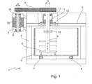
- FIG. 1 shows a vertical section through a mixer.
- the mixer 1 has a mixing container 3 accommodated in a mixer housing 2, which can be rotated about a vertical axis of rotation. To ensure this rotation of the mixing container 3 is rotatably mounted on a ball bearing 4.
- the mixing container may have on its underside an emptying opening (not shown in the figure).
- the mixer housing 2 has a housing cover 5. Inside the mixing container 3, a working tool 6 designed as a mixing tool is arranged inside the mixing container 3, a working tool 6 designed as a mixing tool is arranged. It can be seen that the working tool 6 about a vertical axis, which is spaced from the axis of rotation of the mixing container 3, is rotatable.
- a drive end of the working tool 6 is guided through the housing cover 5 and driven by means of the drive motor 7 via, for example, V-belt 9.
- the work tools 6 are fixed to a tool shaft 8, which has a drive end to which the V-belt 9 engages, and a working end to which the working tools 6 designed as a mixing tool are fastened.
- the tool shaft 8 is formed in two parts in the embodiment shown, wherein the two parts can be connected to each other via the flange 10 or separated from each other. This flange 10 is among other things there, the working tool 6 against another working tool 6, such. B. one Star vortex against a pin vortex swap.
- the work tool if it shows signs of wear, be replaced with a new one.
- both the mixing container 3 and the tool shaft 8 rotate, it can lead to significant lateral forces on the tool shaft 8, which are caused by the material flow through the rotating mixing container 3, especially since the tool shaft is held only on one side in the housing cover 5.
- the size of the shear force depends inter alia on the type of mix and of course on the rotational speed of both mixing container 3 and the working tool 6.
- two tool bearings 11, 12 are provided at the drive end, each bearing the shaft with a diameter D.
- the tool bearings 11, 12 are bolted to the mixer housing 2 or the housing cover 5 via a flange 13.
- the V-belt 9 then engages the drive end of the tool shaft 8.
- the drive motor 7 has a motor shaft 20, which is also held by two motor bearings 14, 15. It can be seen that the diameter d 'of the motor shaft 20 is significantly smaller than the diameter D of the tool shaft 8.
- the belt transmission consisting generally of a set of multiple V-belts or timing belt, a maintenance-intensive machine element. These components must be checked at regular intervals for correct voltage and this must be adjusted if necessary. Likewise, both V-belts and toothed belts are subject to wear and must therefore be replaced at regular intervals.
- the GB 330834 also shows a mixer with a mixing container and a mixing shaft arranged in the tool shaft to which a working tool is attached. This drive shaft is driven by a drive motor.
- the DE 197 12 324 C2 and the DE 39 42 679 A1 show mixing devices for mixing liquids.
- the motors of the mixing device are held by means of rotor bearings.
- this object is achieved by a mixer according to claim 1.
- one of the bearings which is provided for the storage of the tool shaft, simultaneously used for the storage of the motor shaft.
- Motor shaft and tool shaft are therefore directly connected.
- the motor is arranged between the two tool bearings and the motor shaft is preferably mounted by means of the two tool bearings.
- the motor shaft is preferably mounted by means of the two tool bearings.
- the bearings for the tool shaft also serve as a bearing for the motor shaft.
- no distinction can be made in this embodiment between engine and tool shaft, since a portion of the shaft acts as a motor shaft and another portion of the same shaft as a tool shaft.
- a direct drive preferably a direct drive and more preferably a three-phase synchronous motor (servo motor, torque motor, reluctance motor) is used.
- a three-phase synchronous motor servo motor, torque motor, reluctance motor
- the bearing of the motor shaft facing the tool shaft is suitable for absorbing particularly high radial and axial forces. It is a combined radial thrust bearing (Radiax bearing), e.g. designed as a spherical roller or self-aligning ball bearings and particularly preferably as a double-row spherical roller bearings.
- Radiax bearing radial thrust bearing
- a further preferred embodiment provides that the diameter of the motor shaft differs at the two tool bearings, wherein preferably the diameter of the motor shaft d "on the tool shaft facing away from the tool bearing smaller, preferably at least 30%, more preferably at least 50% smaller than the diameter of the motor shaft D at the other tool bearing.
- the motor is expediently arranged in a motor housing, wherein both tool bearings are arranged on or in the motor housing.
- the motor housing having a first outer flange, with which the motor housing and thus the motor is fixed to the mixer housing.
- the motor housing having a second outer flange which is also secured to the mixer housing, wherein the second outer flange preferably has a larger average diameter than the first outer flange.
- the motor housing could for example have a circular cross-section, in which case expediently also the outer flanges have a circular cross-section. In principle, however, other cross sections, such as square or rectangular cross-sections are conceivable. Characterized in that the second outer flange has a larger average diameter, the motor can be easily attached to the mixer housing.
- the mixer housing may include a through-stage opening having a first smaller diameter portion and a second larger diameter portion, the second portion having a mean diameter greater than the mean diameter of the first outer flange and smaller than the average diameter of the second Outside flange is.
- the smallest mean diameter of the passage stage opening in the mixer housing is greater than the largest outer diameter of the working tool. By this measure, the entire work tool including the engine can be removed via the passage step opening.
- both flanges have holes for attaching the flanges to the mixer housing.
- the larger flange may have additional openings, which are preferably larger than the holes for attachment, which are provided so that a tool can access through the opening to the holes or fasteners in the smaller flange. This facilitates the attachment of the motor housing to the mixer housing.
- the tool shaft consists of two parts detachably fastened to one another, wherein one part is connected in one piece with the motor shaft, while the other part carries the working tool.
- the detachable connection can be made via a flange connection.
- the tool shaft may also be formed integrally with the motor shaft.
- FIG. 1 shows an embodiment of the prior art, which has already been described above.
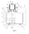
- FIG. 2 shows a first embodiment of the invention.
- the drive motor 7 is accommodated in a motor housing 16, the motor housing 16 being fastened to the mixer cover 5 by means of two outer flanges 13, 17.
- the tool shaft 8 simultaneously acts as a motor shaft 21 at its drive end.
- the motor shaft 21, which is partially formed in the embodiment shown as a hollow shaft is held by the spherical roller bearing 18 and the radial bearing 19.
- the second outer flange 13, which faces the product space, ie the mixing container more, has a smaller outer diameter than the first outer flange 17.
- the entire motor can be inserted from the outside into the housing cover 5, so that first the outer flange with the smaller Outer diameter is inserted into a corresponding stepped bore in the container lid until it rests on the bottom of the extended bore.
- the distance between the two outer flanges 13, 17 is dimensioned such that in the in FIG. 2 shown situation, both flanges can be screwed to the housing cover 5.
- the engine can be easily detached and removed from the container lid.
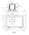
- FIG. 3 which simultaneously shows a second embodiment of the mixer according to the invention.
- the engine including working tool 6 has been released from the housing cover 5, so that the engine including working tool 6 can be removed from the corresponding opening in the container lid.
- the embodiment shown differs from that in FIG. 2 shown embodiment in that the flange 10 is missing, so that here tool shaft and motor shaft are integrally formed.
- the axis of rotation of the working tool is arranged eccentrically to the axis of rotation of the mixing container.
Landscapes
- Chemical & Material Sciences (AREA)
- Chemical Kinetics & Catalysis (AREA)
- Engineering & Computer Science (AREA)
- Mechanical Engineering (AREA)
- Accessories For Mixers (AREA)
- Mixers Of The Rotary Stirring Type (AREA)
- Food-Manufacturing Devices (AREA)
- Processing And Handling Of Plastics And Other Materials For Molding In General (AREA)
- Mixers With Rotating Receptacles And Mixers With Vibration Mechanisms (AREA)
Description
- Die vorliegende Erfindung betrifft einen Mischer mit einem Mischbehälter und einer zumindest teilweise im Mischbehälter angeordneten Werkzeugwelle, wobei die Werkzeugwelle ein Arbeitsende, an dem ein Arbeitswerkzeug befestigt ist oder befestigt werden kann, und ein Antriebsende, welches mittels zweier voneinander beabstandeter Werkzeuglager gelagert ist, aufweist, und wobei ein Antriebsmotor mit einer Motorwelle zum Antreiben der Werkzeugwelle vorgesehen ist.
- Ein solcher Mischer ist beispielsweise bekannt aus der
DE 35 20 409 A1 . Die dort gezeigte Ausführungsform umfasst einen druckfesten Mischer mit einer Einfüllöffnung, einem sich drehenden, eine Entleerungseinrichtung aufweisenden Mischbehälter, mit exzentrisch zur Mischbehälterachse angeordneten Mischwerkzeugen im Inneren des Mischbehälters. - Der bekannte Mischer aus dem Stand der Technik ist schematisch in
Figur 1 wiedergegeben, die einen vertikalen Schnitt durch einen Mischer zeigt. Der Mischer 1 weist einen in einem Mischergehäuse 2 aufgenommenen Mischbehälter 3 auf, der um eine vertikale Drehachse gedreht werden kann. Um diese Drehung zu gewährleisten ist der Mischbehälter 3 auf einem Kugellager 4 drehbar gelagert. Der Mischbehälter kann an seiner Unterseite eine Entleeröffnung aufweisen (in der Figur nicht gezeigt). Das Mischergehäuse 2 weist einen Gehäusedeckel 5 auf. Im Inneren des Mischbehälters 3 ist ein als Mischwerkzeug ausgebildetes Arbeitswerkzeug 6 angeordnet. Man erkennt, dass das Arbeitswerkzeug 6 um eine vertikale Achse, die von der Drehachse des Mischbehälters 3 beabstandet ist, drehbar ist. Zu diesem Zweck wird ein Antriebsende des Arbeitswerkzeuges 6 durch den Gehäusedeckel 5 geführt und mit Hilfe des Antriebsmotors 7 über beispielsweise Keilriemen 9 angetrieben. - Die Arbeitswerkzeuge 6 sind an einer Werkzeugwelle 8 befestigt, die ein Antriebsende, an dem der Keilriemen 9 angreift, und ein Arbeitsende, an dem die als Mischwerkzeug ausgebildeten Arbeitswerkzeuge 6 befestigt sind, aufweist. Die Werkzeugwelle 8 ist in der gezeigten Ausführungsform zweiteilig ausgebildet, wobei die beiden Teile über die Flanschverbindung 10 miteinander verbunden bzw. voneinander getrennt werden können. Diese Flanschverbindung 10 ist u.a. dafür da, das Arbeitswerkzeug 6 gegen ein anderes Arbeitswerkzeug 6, wie z. B. einen Sternwirbler gegen einen Stiftenwirbler, auszutauschen. Zudem kann das Arbeitswerkzeug, wenn es Verschleißerscheinungen zeigt, gegen ein Neues ausgetauscht werden. Da sich sowohl der Mischbehälter 3 als auch die Werkzeugwelle 8 drehen, kann es zu erheblichen Querkräften auf die Werkzeugwelle 8 kommen, welche durch die Materialanströmung durch den drehenden Mischbehälter 3 verursacht werden, zumal die Werkzeugwelle nur an einer Seite in dem Gehäusedeckel 5 gehalten wird. Die Größe der Querkraft hängt u.a. von der Art des Mischgutes und natürlich von der Drehgeschwindigkeit von sowohl Mischbehälter 3 als auch dem Arbeitswerkzeug 6 ab.
- Zum Halten der Werkzeugwelle 8 sind daher am Antriebsende zwei Werkzeuglager 11, 12 vorgesehen, die jeweils die Welle mit einem Durchmesser D lagern. Zum Abfangen der Kräfte sind die Werkzeuglager 11, 12 über einen Flansch 13 am Mischergehäuse 2 bzw. dem Gehäusedeckel 5 verschraubt. Der Keilriemen 9 greift dann an dem Antriebsende der Werkzeugwelle 8 an. Der Antriebsmotor 7 weist eine Motorwelle 20 auf, die ebenfalls über zwei Motorlager 14, 15 gehalten wird. Man erkennt, dass der Durchmesser d' der Motorwelle 20 deutlich kleiner ist als der Durchmesser D der Werkzeugwelle 8.
- Als Antriebsmotor kommen im Stand der Technik hauptsächlich Drehstromasynchronmotoren oder Hydraulikmotoren mit Keilriemen- oder Zahnriemengetriebe, sowie Getriebemotoren vor.
- Allen diesen Antriebsarten ist gemein, dass eine Vielzahl von Elementen zur Drehmomenterzeugung und zur Drehmomentenwandlung sowie zur Aufnahme der Last benötigt werden. Im einfachsten Falle des Asynchronmotors mit entsprechender Lagerung werden mindestens vier Lager, zwei Lager für die Motorwelle und zwei Lager für die Werkzeugwelle, benötigt, die neben den Gewichtskräften zusätzlich auch die hohen Kräfte vom Arbeitswerkzeug sowie die erheblichen Riemenkräfte aufnehmen müssen.
- Wird ein Getriebemotor oder ein separates Getriebe verwendet, müssen für jede weitere Untersetzungsstufe mindestens zwei weitere Lager vorgesehen werden.
- Neben den aufwändigen und dennoch ausfallbehafteten Lagern ist das Riemengetriebe, bestehend im allgemeinen aus einem Satz von mehreren Keilriemen oder Zahnriemen, ein wartungsintensives Maschinenelement. Diese Komponenten müssen in regelmäßigen Intervallen auf korrekte Spannung geprüft und diese muss ggf. angepasst werden. Ebenso sind sowohl Keilals auch Zahnriemen verschleißbehaftet und müssen daher in regelmäßigen Intervallen getauscht werden.
- Die
GB 330834 - Die
DE 197 12 324 C2 und dieDE 39 42 679 A1 zeigen Mischvorrichtungen zum Mischen von Flüssigkeiten. Die Motoren der Mischvorrichtung werden mittels Rotorlagern gehalten. - Vor dem Hintergrund des beschriebenen Standes der Technik ist es daher Aufgabe der vorliegenden Erfindung, einen Mischer bereitzustellen, der einfach und kostengünstig herzustellen ist, ein möglichst hohes Drehmoment in einem weiten Drehzahlbereich und eine minimale Anzahl verschleißbehafteter Bauteile zum Antrieb des Arbeitswerkzeuges besitzt.
- Erfindungsgemäß wird diese Aufgabe durch einen Mischer gemäß Anspruch 1 gelöst.
- Mit anderen Worten wird eines der Lager, welches für die Lagerung der Werkzeugwelle vorgesehen ist, gleichzeitig zur Lagerung der Motorwelle verwendet. Motorwelle und Werkzeugwelle sind, daher direkt miteinander verbunden. Durch diese Maßnahme kann zumindest ein Lager vermieden werden.
- Besonders bevorzugt ist eine Ausführungsform, bei welcher der Motor zwischen den beiden Werkzeuglagern angeordnet ist und die Motorwelle vorzugsweise mittels der beiden Werkzeuglager gelagert ist. Durch diese Ausführungsform kann auf zwei Lager verzichtet werden, da die Lager für die Werkzeugwelle gleichzeitig als Lager für die Motorwelle dienen. Im Grunde genommen kann bei dieser Ausführungsform nicht mehr zwischen Motor- und Werkzeugwelle unterschieden werden, da ein Abschnitt der Welle als Motorwelle und ein anderer Abschnitt derselben Welle als Werkzeugwelle fungiert.
- Als Motor kommt in diesen Fällen vorzugsweise ein Direktantrieb und besonders bevorzugt ein Drehstrom Synchronmotor (Servomotor, Torque-Motor, Reluktanzmotor) zum Einsatz.
- In einer weiteren bevorzugten Ausführungsform ist das der Werkzeugwelle zugewandte Lager der Motorwelle geeignet, besonders hohe radiale und axiale Kräfte aufzunehmen. Es ist als kombiniertes Radial-Axiallager (Radiaxlager), z.B. als ein Pendelrollen- bzw. Pendelkugellager und besonders bevorzugt als zweireihiges Pendelrollenlager ausgeführt.
- Es hat sich gezeigt, dass insbesondere ein zweireihiges Pendelrollenlager die im Betrieb auftretenden Querkräfte am besten aufnehmen kann.
- Eine weitere bevorzugte Ausführungsform sieht vor, dass sich der Durchmesser der Motorwelle an den beiden Werkzeuglagern unterscheidet, wobei vorzugsweise der Durchmesser der Motorwelle d" an dem der Werkzeugwelle abgewandten Werkzeuglager kleiner, vorzugsweise mindestens 30 %, besonders bevorzugt mindestens 50 % kleiner als der Durchmesser der Motorwelle D an dem anderen Werkzeuglager ist.
- Es hat sich gezeigt, dass lediglich das dem Mischbehälter zugewandte Lager einen großen Durchmesser aufweisen muss. Bei geeigneter Dimensionierung der Lager kann das dem Mischbehälter abgewandte Lager erheblich kleiner und damit kostengünstiger dimensioniert werden.
- Der Motor ist zweckmäßigerweise in einem Motorgehäuse angeordnet, wobei beide Werkzeuglager am oder im Motorgehäuse angeordnet sind. Dabei kann das Motorgehäuse einen ersten Außenflansch aufweisen, mit dem das Motorgehäuse und damit der Motor an dem Mischergehäuse befestigt ist. Weiterhin kann in einer besonders bevorzugten Ausführungsform das Motorgehäuse einen zweiten Außenflansch aufweisen, der ebenfalls am Mischergehäuse befestigt ist, wobei der zweite Außenflansch vorzugsweise einen größeren mittleren Durchmesser als der erste Außenflansch aufweist.
- Das Motorgehäuse könnte beispielsweise einen kreisförmigen Querschnitt aufweisen, wobei dann zweckmäßigerweise auch die Außenflansche einen kreisförmigen Querschnitt haben. Grundsätzlich sind jedoch auch andere Querschnitte, beispielsweise quadratische oder rechteckige Querschnitte denkbar. Dadurch, dass der zweite Außenflansch einen größeren mittleren Durchmesser aufweist, kann der Motor einfach am Mischergehäuse befestigt werden. Beispielsweise kann das Mischergehäuse eine Durchgangsstufenöffnung mit einem ersten Abschnitt mit kleinerem mittleren Durchmesser und einen zweiten Abschnitt mit größerem mittleren Durchmesser aufweisen, wobei der zweite Abschnitt einen mittleren Durchmesser aufweist, der größer als der mittlere Durchmesser des ersten Außenflansches und kleiner als der mittlere Durchmesser des zweiten Außenflansches ist. In einer bevorzugten Ausführungsform ist der kleinste mittlere Durchmesser der Durchgangsstufenöffnung im Mischergehäuse größer als der größte Außendurchmesser des Arbeitswerkzeuges. Durch diese Maßnahme kann das gesamte Arbeitswerkzeug samt Motor über die Durchgangsstufenöffnung entnommen werden.
- Typischerweise weisen beide Flansche Bohrungen zur Befestigung der Flansche am Mischergehäuse auf. Dabei kann der größere Flansch zusätzliche Öffnungen aufweisen, die vorzugsweise größer als die Bohrungen zur Befestigung sind, die dafür vorgesehen sind, dass ein Werkzeug durch die Öffnung auf die Bohrungen bzw. Befestigungsmittel im kleineren Flansch zugreifen kann. Dies erleichtert die Befestigung des Motorgehäuses am Mischergehäuse.
- In einer weiteren bevorzugten Ausführungsform besteht die Werkzeugwelle aus zwei lösbar aneinander befestigten Teilen, wobei der eine Teil einstückig mit der Motorwelle verbunden ist, während der andere Teil das Arbeitswerkzeug trägt. Dabei kann die lösbare Verbindung über eine Flanschverbindung erfolgen.
- Alternativ dazu kann die Werkzeugwelle auch einstückig mit der Motorwelle ausgebildet sein.
- Weitere Vorteile, Merkmale und Anwendungsmöglichkeiten der vorliegenden Erfindung werden deutlich anhand der folgenden Beschreibung bevorzugter Ausführungsformen sowie der zugehörigen Figuren.
- Es zeigen:
- Figur 1
- einen Vertikalschnitt durch einen Mischer des Standes der Technik,
- Figur 2
- einen Vertikalschnitt durch eine erste erfindungsgemäße Ausführungsform, und
- Figur 3
- einen Vertikalschnitt durch eine zweite erfindungsgemäße Ausführungsform.
-
Figur 1 zeigt eine Ausführungsform des Standes der Technik, die bereits eingangs beschrieben worden ist. -
Figur 2 zeigt eine erste erfindungsgemäße Ausführungsform. Soweit möglich wurden die gleichen Bezugszeichen für gleiche Teile des Mischers gewählt, die bereits inFigur 1 gezeigt und erläutert wurden. InFigur 2 ist der Antriebsmotor 7 in einem Motorgehäuse 16 aufgenommen, wobei das Motorgehäuse 16 mittels zweier Außenflansche 13, 17 am Mischerdeckel 5 befestigt ist. Man erkennt, dass die Werkzeugwelle 8 an ihrem Antriebsende gleichzeitig als Motorwelle 21 fungiert. Die Motorwelle 21, die bei der gezeigten Ausführungsform teilweise als Hohlwelle ausgebildet ist, wird von dem Pendelrollenlager 18 sowie dem Radiallager 19 gehalten. Der zweite Außenflansch 13, der dem Produktraum, d.h. dem Mischbehälter mehr zugewandt ist, hat einen kleineren Außendurchmesser als der erste Außenflansch 17. Dadurch kann der gesamte Motor von der Außenseite in den Gehäusedeckel 5 eingesetzt werden kann, so dass zunächst der Außenflansch mit dem kleineren Außendurchmesser in eine entsprechende gestufte Bohrung in dem Behälterdeckel eingesetzt wird bis er am Boden der erweiterten Bohrung aufliegt. Der Abstand der beiden Außenflansche 13, 17 ist derart dimensioniert, dass in der inFigur 2 gezeigten Situation beide Flansche mit dem Gehäusedeckel 5 verschraubt werden können. - Bei Bedarf kann somit der Motor leicht vom Behälterdeckel gelöst und entnommen werden.
- Eine solche Situation ist in
Figur 3 gezeigt, die gleichzeitig eine zweite erfindungsgemäße Ausführungsform des Mischers zeigt. Hier ist der Motor samt Arbeitswerkzeug 6 von dem Gehäusedeckel 5 gelöst worden, so dass der Motor samt Arbeitswerkzeug 6 aus der entsprechenden Öffnung im Behälterdeckel entnommen werden kann. Die inFigur 3 gezeigte Ausführungsform unterscheidet sich von der inFigur 2 gezeigten Ausführungsform dadurch, dass die Flanschverbindung 10 fehlt, so dass hier Werkzeugwelle und Motorwelle einstückig ausgebildet sind. In beiden gezeigten Ausführungsformen ist die Drehachse des Arbeitswerkzeugs exzentrisch zur Drehachse des Mischbehälter angeordnet. - Durch die Integration des Motors in eine robuste Lagerungseinheit zur Aufnahme der Kräfte und Momente des Arbeitswerkzeuges entsteht eine Einheit mit minimalem Wartungsaufwand und höchstmöglicher Zuverlässigkeit. Es wird nur eine Welle in zwei Lagern geführt. Diese Welle übernimmt sowohl die Kräfte des Motors (z. B. Gewichtskräfte, magnetische Restkräfte) als auch die Kräfte des Arbeitswerkzeuges (Wirbler, Kneter usw.). Eine eventuell notwendige Variation der Drehzahl kann durch die Verwendung eines Frequenzumrichters ermöglicht werden.
-
- 1
- Mischer
- 2
- Mischergehäuse
- 3
- Mischbehälter
- 4
- Kugellager
- 5
- Gehäusedeckel
- 6
- Arbeitswerkzeug
- 7
- Antriebsmotor
- 8
- Werkzeugwelle
- 9
- Keilriemen
- 10
- Flanschverbindung
- 11, 12
- Werkzeuglager
- 13
- Flansch
- 14, 15
- Motorlager
- 16
- Motorgehäuse
- 17
- Flansch
- 18
- Pendelrollenlager
- 19
- Radiallager
- 20 ,21
- Motorwelle
- 22
- Öffnung für Montagewerkzeug
Claims (11)
- Mischer mit einem Mischbehälter und einer zumindest teilweise im Mischbehälter angeordneten Werkzeugwelle (8), wobei die Werkzeugwelle ein Arbeitsende, an dem ein Arbeitswerkzeug (6) befestigt ist oder befestigt werden kann, und ein Antriebsende, welches mittels zweier voneinander beabstandeter Werkzeuglager gelagert ist, aufweist, wobei ein Antriebsmotor (7) mit einer Motorwelle (21) zum Antreiben der Werkzeugwelle (8) vorgesehen ist, dadurch gekennzeichnet, dass die Motorwelle (21) von zumindest einem der beiden voneinander beabstandeten Werkzeuglager gelagert ist, und dass eines der Lager, vorzugsweise das näher am Arbeitsende der Werkzeugwelle (8) angeordnete Lager ein Radiaxlager (18), vorzugsweise ein Pendelrollenlager bzw. Pendelkugellager und besonders bevorzugt ein zweireihiges Pendelrollenlager (18) ist.
- Mischer nach Anspruch 1, dadurch gekennzeichnet, dass der Motor zwischen den beiden Werkzeuglagern angeordnet ist und die Motorwelle (21) vorzugsweise mittels der beiden Werkzeuglager gelagert ist, so dass die Werkzeugwelle auch als Motorwelle dient.
- Mischer nach Anspruch 1 oder 2, dadurch gekennzeichnet, dass der Motor ein Direktantrieb, vorzugsweise ein Drehstromsynchronmotor, vorzugsweise ein Torque-Motor, Servomotor oder Reluktanzmotor ist.
- Mischer nach einem der Ansprüche 1 bis 3, dadurch gekennzeichnet, dass sich der Durchmesser der Motorwelle (21) an den beiden Werkzeuglagern unterscheidet, wobei vorzugsweise der Durchmesser der Motorwelle (21) an dem der Werkzeugwelle (8) abgewandten Werkzeuglager kleiner, vorzugsweise mindestens 30 % und besonders bevorzugt mindestens 50 % kleiner als der Durchmesser der Motorwelle (21) an dem anderen Werkzeuglager ist.
- Mischer nach einem der Ansprüche 1 bis 4, dadurch gekennzeichnet, dass der Motor in einem Motorgehäuse (16) angeordnet ist, wobei beide Werkzeuglager am oder im Motorgehäuse (16) angeordnet sind.
- Mischer nach Anspruch 5, dadurch gekennzeichnet, dass das Motorgehäuse (16) einen ersten Außenflansch (13) und der Mischer ein Mischergehäuse (2), in dem der Mischbehälter (3) angeordnet ist, aufweist, wobei der Außenflansch am Mischergehäuse besonders bevorzugt am Gehäusedeckel (5) befestigt ist.
- Mischer nach Anspruch 6, dadurch gekennzeichnet, dass das Motorgehäuse (16) einen zweiten Außenflansch (17) aufweist, der ebenfalls am Mischergehäuse befestigt ist, wobei der zweite Außenflansch (17) vorzugsweise einen größeren mittleren Durchmesser als der erste Außenflansch (13) aufweist.
- Mischer nach Anspruch 7, dadurch gekennzeichnet, dass das Mischergehäuse eine Durchgangsstufenöffnung mit einem ersten Abschnitt mit kleinerem mittlerem Durchmesser und einem zweiten Abschnitt mit größerem mittleren Durchmesser aufweist, wobei der zweite Abschnitt einen mittleren Durchmesser aufweist, der größer als der mittlere Durchmesser des ersten Außenflansches (13) ist und kleiner als der mittlere Durchmesser des zweiten Außenflansches (17) ist.
- Mischer nach Anspruch 7, dadurch gekennzeichnet, dass die kleinste Durchgangsstufenöffnung größer als der größte Außendurchmesser des Arbeitswerkzeuges (6) ist.
- Mischer nach einem der Ansprüche 1 bis 9, dadurch gekennzeichnet, dass die Werkzeugwelle (8) zwei lösbar aneinander befestigte Abschnitte aufweist, wobei einer der Abschnitte einstückig mit der Motorwelle (21) ausgebildet ist.
- Mischer nach einem der Ansprüche 1 bis 9, dadurch gekennzeichnet, dass die Werkzeugwelle (8) und die Motorwelle (21) einstückig ausgebildet sind.
Priority Applications (1)
| Application Number | Priority Date | Filing Date | Title |
|---|---|---|---|
| PL09764834T PL2358467T3 (pl) | 2008-12-17 | 2009-12-04 | Mieszalnik |
Applications Claiming Priority (2)
| Application Number | Priority Date | Filing Date | Title |
|---|---|---|---|
| DE102008054842A DE102008054842A1 (de) | 2008-12-17 | 2008-12-17 | Mischer |
| PCT/EP2009/066458 WO2010076120A1 (de) | 2008-12-17 | 2009-12-04 | Mischer mit drehbarem mischbehälter |
Publications (2)
| Publication Number | Publication Date |
|---|---|
| EP2358467A1 EP2358467A1 (de) | 2011-08-24 |
| EP2358467B1 true EP2358467B1 (de) | 2014-07-16 |
Family
ID=41666436
Family Applications (1)
| Application Number | Title | Priority Date | Filing Date |
|---|---|---|---|
| EP09764834.9A Active EP2358467B1 (de) | 2008-12-17 | 2009-12-04 | Mischer |
Country Status (20)
| Country | Link |
|---|---|
| US (1) | US9694331B2 (de) |
| EP (1) | EP2358467B1 (de) |
| JP (1) | JP5610163B2 (de) |
| KR (1) | KR101665493B1 (de) |
| CN (1) | CN102300629B (de) |
| AU (1) | AU2009334941B2 (de) |
| BR (1) | BRPI0923457B1 (de) |
| CA (1) | CA2743256C (de) |
| DE (1) | DE102008054842A1 (de) |
| DK (1) | DK2358467T3 (de) |
| ES (1) | ES2495747T3 (de) |
| MX (1) | MX2011006161A (de) |
| PE (1) | PE20120504A1 (de) |
| PL (1) | PL2358467T3 (de) |
| PT (1) | PT2358467E (de) |
| RU (1) | RU2521571C2 (de) |
| TW (1) | TWI523682B (de) |
| UA (1) | UA105912C2 (de) |
| WO (1) | WO2010076120A1 (de) |
| ZA (1) | ZA201103278B (de) |
Cited By (1)
| Publication number | Priority date | Publication date | Assignee | Title |
|---|---|---|---|---|
| US11684900B2 (en) | 2018-03-16 | 2023-06-27 | Maschinenfabrik Gustav Eirich Gmbh & Co. Kg | Hygienic mixer which is pivotably mounted |
Families Citing this family (34)
| Publication number | Priority date | Publication date | Assignee | Title |
|---|---|---|---|---|
| DE102010027885A1 (de) * | 2010-04-16 | 2012-02-09 | Maschinenfabrik Gustav Eirich Gmbh & Co. Kg | Mischvorrichtung mit Verschleißschutzauskleidung |
| CN102327755A (zh) * | 2010-07-12 | 2012-01-25 | 南通全技纺织涂层有限公司 | 用于织物涂层浆料的搅拌机 |
| US8845940B2 (en) | 2012-10-25 | 2014-09-30 | Carboncure Technologies Inc. | Carbon dioxide treatment of concrete upstream from product mold |
| CN102908929A (zh) * | 2012-11-18 | 2013-02-06 | 苏州蓝王机床工具科技有限公司 | 一种液态类物料搅拌机 |
| USD715346S1 (en) * | 2013-01-10 | 2014-10-14 | Nitto Denko Corporation | Container for mixer |
| USD715344S1 (en) * | 2013-01-10 | 2014-10-14 | Nitto Denko Corporation | Container for mixer |
| USD715343S1 (en) * | 2013-01-10 | 2014-10-14 | Nitto Denko Corporation | Container for mixer |
| USD715345S1 (en) * | 2013-01-10 | 2014-10-14 | Nitto Denko Corporation | Container for mixer |
| EP2951122B1 (de) | 2013-02-04 | 2020-05-27 | Carboncure Technologies Inc. | System und verfahren zur anwendung von kohlendioxid bei der herstellung von beton |
| US9376345B2 (en) | 2013-06-25 | 2016-06-28 | Carboncure Technologies Inc. | Methods for delivery of carbon dioxide to a flowable concrete mix |
| US9388072B2 (en) | 2013-06-25 | 2016-07-12 | Carboncure Technologies Inc. | Methods and compositions for concrete production |
| US10927042B2 (en) | 2013-06-25 | 2021-02-23 | Carboncure Technologies, Inc. | Methods and compositions for concrete production |
| RU2534871C1 (ru) * | 2013-06-27 | 2014-12-10 | Федеральное государственное бюджетное образовательное учреждение высшего профессионального образования "Ярославский государственный технический университет" | Бетономешалка с импульсной стержневой мешалкой со свирелеобразными стержнями |
| WO2015123769A1 (en) | 2014-02-18 | 2015-08-27 | Carboncure Technologies, Inc. | Carbonation of cement mixes |
| CA2943791C (en) | 2014-04-07 | 2023-09-05 | Carboncure Technologies Inc. | Integrated carbon dioxide capture |
| DE102014117509A1 (de) * | 2014-11-28 | 2016-06-02 | Maschinenfabrik Gustav Eirich Gmbh & Co. Kg | Vorrichtung zur Aufbereitung und Kühlung von Gießereiformsand |
| US20180008944A1 (en) * | 2015-01-19 | 2018-01-11 | Ulvac, Inc. | Mixing Device |
| CN105170001B (zh) * | 2015-08-25 | 2017-09-15 | 晋江兴翼机械有限公司 | 组合式搅拌装置 |
| DE102016106536A1 (de) * | 2016-04-08 | 2017-10-12 | Maschinenfabrik Gustav Eirich Gmbh & Co. Kg | Mischwelle |
| AU2017249444B2 (en) | 2016-04-11 | 2022-08-18 | Carboncure Technologies Inc. | Methods and compositions for treatment of concrete wash water |
| CN106582394A (zh) * | 2016-12-09 | 2017-04-26 | 陈红 | 一种干电池生产工艺用原料密封混合设备 |
| MX2019015651A (es) | 2017-06-20 | 2020-08-03 | Carboncure Tech Inc | Métodos y composiciones para tratamiento de agua de lavado de concreto. |
| DE102018106187A1 (de) * | 2018-03-16 | 2019-09-19 | Maschinenfabrik Gustav Eirich Gmbh & Co. Kg | Mischvorrichtung mit Verschlusselement |
| DE102018106184A1 (de) | 2018-03-16 | 2019-09-19 | Maschinenfabrik Gustav Eirich Gmbh & Co. Kg | Mischvorrichtung mit Dichtung |
| DE102018106188A1 (de) * | 2018-03-16 | 2019-09-19 | Maschinenfabrik Gustav Eirich Gmbh & Co. Kg | Vorrichtung zur Umsetzung einer Linearbewegung in einem stationären System in eine Drehbewegung um eine Schwenkachse in einem sich um eine Drehachse drehenden System |
| DE102018106192A1 (de) * | 2018-03-16 | 2019-09-19 | Maschinenfabrik Gustav Eirich Gmbh & Co. Kg | Mischvorrichtung mit zweiteiligem Verschlussdeckel |
| CN108854759A (zh) * | 2018-06-19 | 2018-11-23 | 广州高蒂丝生物科技有限公司 | 一种化妆品生产用高效原料混合装置 |
| CN108771988A (zh) * | 2018-06-21 | 2018-11-09 | 陈文� | 一种流体动态混合器 |
| EP3608015B1 (de) * | 2018-08-08 | 2021-10-06 | Harro Höfliger Verpackungsmaschinen GmbH | Pulverbereitstellungseinrichtung für einen pulverdosierer |
| WO2020217232A1 (en) | 2019-04-26 | 2020-10-29 | Carboncure Technologies Inc. | Carbonation of concrete aggregates |
| US12521908B2 (en) | 2020-06-12 | 2026-01-13 | Carboncure Technologies Inc. | Methods and compositions for delivery of carbon dioxide |
| CN114160753A (zh) * | 2021-11-26 | 2022-03-11 | 马鞍山市绿科环保科技有限公司 | 一种在铸造砂处理固体废弃物中分选原砂的方法 |
| US20240216880A1 (en) * | 2022-12-29 | 2024-07-04 | Rivian Ip Holdings, Llc | Systems and methods for mixing |
| CN118142410B (zh) * | 2024-05-13 | 2024-08-23 | 上海智滨科技有限公司 | 旋转容器混合器 |
Citations (3)
| Publication number | Priority date | Publication date | Assignee | Title |
|---|---|---|---|---|
| DE3942679A1 (de) * | 1989-12-22 | 1991-06-27 | Ekato Ind Anlagen Verwalt | Mischvorrichtung |
| DE19712324C2 (de) * | 1997-03-24 | 2000-05-11 | Renner Gmbh | Umwälzpumpe oder Rührwerk für erwärmte chemische Lösungen |
| DE60015482T2 (de) * | 1999-12-24 | 2005-10-27 | Takashi Nishimoto | Verfahren und Vorrichtung zur Behandlung von kontaminierten Flüssigkeiten |
Family Cites Families (33)
| Publication number | Priority date | Publication date | Assignee | Title |
|---|---|---|---|---|
| US1435289A (en) * | 1918-01-28 | 1922-11-14 | Gilbert Co A C | Churn or agitator |
| US1351243A (en) * | 1919-02-21 | 1920-08-31 | French Battery & Carbon Co | Mixing-machine |
| US1718745A (en) * | 1927-06-01 | 1929-06-25 | Laing Lawrence | Mixer |
| US1783651A (en) * | 1929-07-15 | 1930-12-02 | Homer R Johnson | Kitchen utensil |
| GB330834A (en) | 1929-09-07 | 1930-06-19 | James Flynn Turner | Improvements in or relating to foundry sand mixer |
| US2008684A (en) * | 1931-10-27 | 1935-07-23 | Mixing Equipment Company Inc | Emulsifying unit |
| US1935857A (en) * | 1932-11-18 | 1933-11-21 | Nachumsohn Irving | Electric cream-whipper and drink mixer |
| US2250838A (en) * | 1939-12-19 | 1941-07-29 | Geneva Processes Inc | Mixing device |
| US3140861A (en) * | 1962-08-06 | 1964-07-14 | Donald E Krup | Mixing device |
| DE1301874B (de) * | 1967-10-03 | 1969-08-28 | Ahrenberg Kurt | Befeuchtungsverfahren und -vorrichtung fuer Mischgueter, insbesondere Giessereiformsande |
| DE2323579C2 (de) * | 1973-05-10 | 1975-03-06 | Gerd 5138 Heinsberg Meuser | Mischer für trockenes oder erdfeuchtes Mischgut z.B. Beton |
| US4159879A (en) * | 1976-03-18 | 1979-07-03 | Pioneer Associates #2 | Bread making machine |
| DE3520409A1 (de) * | 1985-06-07 | 1986-12-11 | Hubert Eirich | Druckfester mischer |
| CN2055406U (zh) | 1989-08-29 | 1990-04-04 | 冯连春 | 立式顺流搅拌机 |
| JP2900296B2 (ja) | 1992-04-16 | 1999-06-02 | オルガノ株式会社 | 緩急撹拌槽 |
| RU2085275C1 (ru) * | 1993-07-29 | 1997-07-27 | Товарищество с ограниченной ответственностью Фирма "Диапазон" | Гидрокавитационный смеситель-диспергатор суспензии |
| US5813758A (en) * | 1993-12-10 | 1998-09-29 | Ahlstrom Machinery Inc. | Concentric ring fluidizing mixer |
| RU2083095C1 (ru) * | 1994-10-13 | 1997-07-10 | Юрий Ильич Деревцов | Маслобойка для сбивания масла из молочного сырья |
| DE19749223A1 (de) * | 1997-11-07 | 1999-05-20 | Thomas Beindorf | Rührwerksvorrichtung |
| US6435262B1 (en) * | 2001-03-16 | 2002-08-20 | New Ideas, Llc | Foundry sand |
| CN2541036Y (zh) | 2002-03-05 | 2003-03-26 | 任荣泽 | 翻酱机 |
| US6685358B2 (en) | 2002-04-29 | 2004-02-03 | Conocophillips Company | Hydraulic motor for use in high-pressure environment |
| US6698934B2 (en) * | 2002-04-29 | 2004-03-02 | Conocophillips Company | Agitator drive |
| JP4107571B2 (ja) | 2002-08-13 | 2008-06-25 | 株式会社富喜製作所 | 液体と気体との撹拌混合装置 |
| JP2004121989A (ja) | 2002-10-02 | 2004-04-22 | Nachi Fujikoshi Corp | 屎尿攪拌装置。 |
| US7207711B2 (en) * | 2002-12-23 | 2007-04-24 | Premark Feg L.L.C. | Mixing device with variable speed drive and related control features |
| JP2006305413A (ja) | 2005-04-26 | 2006-11-09 | Sharp Corp | 生ゴミ処理機 |
| US7913878B1 (en) * | 2005-08-29 | 2011-03-29 | Nestec, S. A. | Terminal orifice processor |
| DE102005058396B3 (de) * | 2005-12-07 | 2007-02-08 | Ab Skf | Lageranordnung |
| JP2007247849A (ja) | 2006-03-17 | 2007-09-27 | Ntn Corp | 攪拌機用調心輪付き円筒ころ軸受 |
| CN201050598Y (zh) | 2007-03-24 | 2008-04-23 | 虞培清 | 一种专用机械密封 |
| DE102007027298A1 (de) * | 2007-06-11 | 2008-12-18 | Maschinenfabrik Gustav Eirich Gmbh & Co. Kg | Verfahren zur Aufbereitung von Formsand |
| DE102008041104A1 (de) * | 2008-08-07 | 2010-02-11 | Maschinenfabrik Gustav Eirich Gmbh & Co. Kg | Mischvorrichtung mit Induktionsheizung |
-
2008
- 2008-12-17 DE DE102008054842A patent/DE102008054842A1/de not_active Withdrawn
-
2009
- 2009-11-19 TW TW098139323A patent/TWI523682B/zh active
- 2009-12-04 PE PE2011001200A patent/PE20120504A1/es active IP Right Grant
- 2009-12-04 UA UAA201108861A patent/UA105912C2/uk unknown
- 2009-12-04 JP JP2011541307A patent/JP5610163B2/ja active Active
- 2009-12-04 DK DK09764834.9T patent/DK2358467T3/da active
- 2009-12-04 MX MX2011006161A patent/MX2011006161A/es active IP Right Grant
- 2009-12-04 RU RU2011129206/05A patent/RU2521571C2/ru active
- 2009-12-04 KR KR1020117016648A patent/KR101665493B1/ko active Active
- 2009-12-04 AU AU2009334941A patent/AU2009334941B2/en active Active
- 2009-12-04 US US13/140,472 patent/US9694331B2/en active Active
- 2009-12-04 WO PCT/EP2009/066458 patent/WO2010076120A1/de not_active Ceased
- 2009-12-04 CN CN200980151667.9A patent/CN102300629B/zh active Active
- 2009-12-04 EP EP09764834.9A patent/EP2358467B1/de active Active
- 2009-12-04 PL PL09764834T patent/PL2358467T3/pl unknown
- 2009-12-04 ES ES09764834.9T patent/ES2495747T3/es active Active
- 2009-12-04 CA CA2743256A patent/CA2743256C/en active Active
- 2009-12-04 BR BRPI0923457-8A patent/BRPI0923457B1/pt active IP Right Grant
- 2009-12-04 PT PT97648349T patent/PT2358467E/pt unknown
-
2011
- 2011-05-05 ZA ZA2011/03278A patent/ZA201103278B/en unknown
Patent Citations (3)
| Publication number | Priority date | Publication date | Assignee | Title |
|---|---|---|---|---|
| DE3942679A1 (de) * | 1989-12-22 | 1991-06-27 | Ekato Ind Anlagen Verwalt | Mischvorrichtung |
| DE19712324C2 (de) * | 1997-03-24 | 2000-05-11 | Renner Gmbh | Umwälzpumpe oder Rührwerk für erwärmte chemische Lösungen |
| DE60015482T2 (de) * | 1999-12-24 | 2005-10-27 | Takashi Nishimoto | Verfahren und Vorrichtung zur Behandlung von kontaminierten Flüssigkeiten |
Cited By (1)
| Publication number | Priority date | Publication date | Assignee | Title |
|---|---|---|---|---|
| US11684900B2 (en) | 2018-03-16 | 2023-06-27 | Maschinenfabrik Gustav Eirich Gmbh & Co. Kg | Hygienic mixer which is pivotably mounted |
Also Published As
| Publication number | Publication date |
|---|---|
| PE20120504A1 (es) | 2012-05-10 |
| RU2011129206A (ru) | 2013-01-27 |
| KR101665493B1 (ko) | 2016-10-24 |
| TWI523682B (zh) | 2016-03-01 |
| JP2012512017A (ja) | 2012-05-31 |
| MX2011006161A (es) | 2011-07-28 |
| PL2358467T3 (pl) | 2014-11-28 |
| EP2358467A1 (de) | 2011-08-24 |
| BRPI0923457B1 (pt) | 2020-02-18 |
| DK2358467T3 (da) | 2014-09-22 |
| WO2010076120A1 (de) | 2010-07-08 |
| JP5610163B2 (ja) | 2014-10-22 |
| PT2358467E (pt) | 2014-08-29 |
| AU2009334941A1 (en) | 2011-07-07 |
| CA2743256C (en) | 2017-03-07 |
| TW201029732A (en) | 2010-08-16 |
| CN102300629B (zh) | 2016-08-03 |
| ZA201103278B (en) | 2012-07-25 |
| US9694331B2 (en) | 2017-07-04 |
| UA105912C2 (uk) | 2014-07-10 |
| AU2009334941B2 (en) | 2012-09-20 |
| BRPI0923457A2 (pt) | 2016-01-12 |
| ES2495747T3 (es) | 2014-09-17 |
| CN102300629A (zh) | 2011-12-28 |
| US20110249527A1 (en) | 2011-10-13 |
| DE102008054842A1 (de) | 2010-07-01 |
| KR20110097959A (ko) | 2011-08-31 |
| CA2743256A1 (en) | 2010-07-08 |
| RU2521571C2 (ru) | 2014-06-27 |
Similar Documents
| Publication | Publication Date | Title |
|---|---|---|
| EP2358467B1 (de) | Mischer | |
| DE102008064815B3 (de) | Spindelmotor mit fluiddynamischem Lagersystem und feststehender WeIle | |
| EP2255923B1 (de) | Rundschalttisch | |
| DE102009017014A1 (de) | Getriebe, insbesondere Planetengetriebe mit einem Flansch und einem Hohlrad | |
| EP2194018A2 (de) | Hebevorrichtung | |
| EP2343254B1 (de) | Trommelmotor | |
| DE3904141A1 (de) | Elastisch gelagerte antriebseinheit | |
| EP3650590B1 (de) | Spinnmaschine sowie spindelbank | |
| EP2174003A2 (de) | Vorrichtung zur erzeugung von energie aus einer fluidströmung | |
| DE102015220996A1 (de) | Zweistückige Drehmomentstütze | |
| DE102021002929A1 (de) | Getriebe mit Gehäuse, welches ein Unterteil und ein Deckelteil, aufweist | |
| EP2110201B1 (de) | Elektrischer Linearantrieb | |
| DE10212671B4 (de) | Kegelradausgleichsgetriebe | |
| EP1988311B1 (de) | Lagereinheit und damit ausgestattete Lineareinheit | |
| DE102017010372A1 (de) | Antrieb, aufweisend ein über ein Summiergetriebe von Elektromotoren antreibbares Getriebe | |
| DE19748683C1 (de) | Drehmomentwandler | |
| DE102008059247A1 (de) | Motorisch angetriebenes Winkelschleifgerät | |
| EP1847337B1 (de) | Antriebsanordnung für einen in einem Gehäuse gelagerten Richtrotor einer Richtmaschine zum Geraderichten von Draht | |
| DE19809014C2 (de) | Doppelkurbeltrieb | |
| DE102018117898A1 (de) | Presse mit Sensor zum Messen der Presskraft | |
| DE102004058635C5 (de) | Geteiltes Getriebegehäuse für ein Schiffsgetriebe | |
| EP1767087B1 (de) | Befestigungsanordnung einer Messerklinge an einer Mischschnecke eines Futtermischwagens | |
| DE202023106188U1 (de) | Impeller mit Außenantrieb für ein Luftfahrzeug | |
| EP4283161A1 (de) | Planetengetriebe mit verbessertem lagerflansch | |
| DE29518673U1 (de) | Hubschrauber, insbesondere Modellhubschrauber |
Legal Events
| Date | Code | Title | Description |
|---|---|---|---|
| PUAI | Public reference made under article 153(3) epc to a published international application that has entered the european phase |
Free format text: ORIGINAL CODE: 0009012 |
|
| 17P | Request for examination filed |
Effective date: 20110517 |
|
| AK | Designated contracting states |
Kind code of ref document: A1 Designated state(s): AT BE BG CH CY CZ DE DK EE ES FI FR GB GR HR HU IE IS IT LI LT LU LV MC MK MT NL NO PL PT RO SE SI SK SM TR |
|
| DAX | Request for extension of the european patent (deleted) | ||
| 17Q | First examination report despatched |
Effective date: 20120402 |
|
| GRAP | Despatch of communication of intention to grant a patent |
Free format text: ORIGINAL CODE: EPIDOSNIGR1 |
|
| INTG | Intention to grant announced |
Effective date: 20140204 |
|
| RAP1 | Party data changed (applicant data changed or rights of an application transferred) |
Owner name: MASCHINENFABRIK GUSTAV EIRICH GMBH & CO. KG |
|
| GRAS | Grant fee paid |
Free format text: ORIGINAL CODE: EPIDOSNIGR3 |
|
| GRAA | (expected) grant |
Free format text: ORIGINAL CODE: 0009210 |
|
| AK | Designated contracting states |
Kind code of ref document: B1 Designated state(s): AT BE BG CH CY CZ DE DK EE ES FI FR GB GR HR HU IE IS IT LI LT LU LV MC MK MT NL NO PL PT RO SE SI SK SM TR |
|
| REG | Reference to a national code |
Ref country code: GB Ref legal event code: FG4D Free format text: NOT ENGLISH |
|
| REG | Reference to a national code |
Ref country code: CH Ref legal event code: EP |
|
| REG | Reference to a national code |
Ref country code: IE Ref legal event code: FG4D Free format text: LANGUAGE OF EP DOCUMENT: GERMAN |
|
| REG | Reference to a national code |
Ref country code: AT Ref legal event code: REF Ref document number: 677237 Country of ref document: AT Kind code of ref document: T Effective date: 20140815 |
|
| REG | Reference to a national code |
Ref country code: DE Ref legal event code: R096 Ref document number: 502009009658 Country of ref document: DE Effective date: 20140828 |
|
| REG | Reference to a national code |
Ref country code: PT Ref legal event code: SC4A Free format text: AVAILABILITY OF NATIONAL TRANSLATION Effective date: 20140814 |
|
| REG | Reference to a national code |
Ref country code: NL Ref legal event code: T3 Ref country code: ES Ref legal event code: FG2A Ref document number: 2495747 Country of ref document: ES Kind code of ref document: T3 Effective date: 20140917 |
|
| REG | Reference to a national code |
Ref country code: DK Ref legal event code: T3 Effective date: 20140915 |
|
| REG | Reference to a national code |
Ref country code: SE Ref legal event code: TRGR |
|
| REG | Reference to a national code |
Ref country code: NO Ref legal event code: T2 Effective date: 20140716 |
|
| REG | Reference to a national code |
Ref country code: PL Ref legal event code: T3 |
|
| REG | Reference to a national code |
Ref country code: LT Ref legal event code: MG4D |
|
| PG25 | Lapsed in a contracting state [announced via postgrant information from national office to epo] |
Ref country code: LT Free format text: LAPSE BECAUSE OF FAILURE TO SUBMIT A TRANSLATION OF THE DESCRIPTION OR TO PAY THE FEE WITHIN THE PRESCRIBED TIME-LIMIT Effective date: 20140716 Ref country code: GR Free format text: LAPSE BECAUSE OF FAILURE TO SUBMIT A TRANSLATION OF THE DESCRIPTION OR TO PAY THE FEE WITHIN THE PRESCRIBED TIME-LIMIT Effective date: 20141017 Ref country code: BG Free format text: LAPSE BECAUSE OF FAILURE TO SUBMIT A TRANSLATION OF THE DESCRIPTION OR TO PAY THE FEE WITHIN THE PRESCRIBED TIME-LIMIT Effective date: 20141016 |
|
| PG25 | Lapsed in a contracting state [announced via postgrant information from national office to epo] |
Ref country code: CY Free format text: LAPSE BECAUSE OF FAILURE TO SUBMIT A TRANSLATION OF THE DESCRIPTION OR TO PAY THE FEE WITHIN THE PRESCRIBED TIME-LIMIT Effective date: 20140716 Ref country code: LV Free format text: LAPSE BECAUSE OF FAILURE TO SUBMIT A TRANSLATION OF THE DESCRIPTION OR TO PAY THE FEE WITHIN THE PRESCRIBED TIME-LIMIT Effective date: 20140716 Ref country code: IS Free format text: LAPSE BECAUSE OF FAILURE TO SUBMIT A TRANSLATION OF THE DESCRIPTION OR TO PAY THE FEE WITHIN THE PRESCRIBED TIME-LIMIT Effective date: 20141116 |
|
| REG | Reference to a national code |
Ref country code: DE Ref legal event code: R097 Ref document number: 502009009658 Country of ref document: DE |
|
| PG25 | Lapsed in a contracting state [announced via postgrant information from national office to epo] |
Ref country code: EE Free format text: LAPSE BECAUSE OF FAILURE TO SUBMIT A TRANSLATION OF THE DESCRIPTION OR TO PAY THE FEE WITHIN THE PRESCRIBED TIME-LIMIT Effective date: 20140716 Ref country code: RO Free format text: LAPSE BECAUSE OF FAILURE TO SUBMIT A TRANSLATION OF THE DESCRIPTION OR TO PAY THE FEE WITHIN THE PRESCRIBED TIME-LIMIT Effective date: 20140716 Ref country code: CZ Free format text: LAPSE BECAUSE OF FAILURE TO SUBMIT A TRANSLATION OF THE DESCRIPTION OR TO PAY THE FEE WITHIN THE PRESCRIBED TIME-LIMIT Effective date: 20140716 Ref country code: SK Free format text: LAPSE BECAUSE OF FAILURE TO SUBMIT A TRANSLATION OF THE DESCRIPTION OR TO PAY THE FEE WITHIN THE PRESCRIBED TIME-LIMIT Effective date: 20140716 |
|
| PLBE | No opposition filed within time limit |
Free format text: ORIGINAL CODE: 0009261 |
|
| STAA | Information on the status of an ep patent application or granted ep patent |
Free format text: STATUS: NO OPPOSITION FILED WITHIN TIME LIMIT |
|
| 26N | No opposition filed |
Effective date: 20150417 |
|
| PG25 | Lapsed in a contracting state [announced via postgrant information from national office to epo] |
Ref country code: LU Free format text: LAPSE BECAUSE OF FAILURE TO SUBMIT A TRANSLATION OF THE DESCRIPTION OR TO PAY THE FEE WITHIN THE PRESCRIBED TIME-LIMIT Effective date: 20141204 |
|
| REG | Reference to a national code |
Ref country code: IE Ref legal event code: MM4A |
|
| PG25 | Lapsed in a contracting state [announced via postgrant information from national office to epo] |
Ref country code: IE Free format text: LAPSE BECAUSE OF NON-PAYMENT OF DUE FEES Effective date: 20141204 |
|
| PG25 | Lapsed in a contracting state [announced via postgrant information from national office to epo] |
Ref country code: SI Free format text: LAPSE BECAUSE OF FAILURE TO SUBMIT A TRANSLATION OF THE DESCRIPTION OR TO PAY THE FEE WITHIN THE PRESCRIBED TIME-LIMIT Effective date: 20140716 |
|
| REG | Reference to a national code |
Ref country code: FR Ref legal event code: PLFP Year of fee payment: 7 |
|
| PG25 | Lapsed in a contracting state [announced via postgrant information from national office to epo] |
Ref country code: SM Free format text: LAPSE BECAUSE OF FAILURE TO SUBMIT A TRANSLATION OF THE DESCRIPTION OR TO PAY THE FEE WITHIN THE PRESCRIBED TIME-LIMIT Effective date: 20140716 |
|
| PG25 | Lapsed in a contracting state [announced via postgrant information from national office to epo] |
Ref country code: MC Free format text: LAPSE BECAUSE OF FAILURE TO SUBMIT A TRANSLATION OF THE DESCRIPTION OR TO PAY THE FEE WITHIN THE PRESCRIBED TIME-LIMIT Effective date: 20140716 |
|
| PG25 | Lapsed in a contracting state [announced via postgrant information from national office to epo] |
Ref country code: MT Free format text: LAPSE BECAUSE OF FAILURE TO SUBMIT A TRANSLATION OF THE DESCRIPTION OR TO PAY THE FEE WITHIN THE PRESCRIBED TIME-LIMIT Effective date: 20140716 Ref country code: HR Free format text: LAPSE BECAUSE OF FAILURE TO SUBMIT A TRANSLATION OF THE DESCRIPTION OR TO PAY THE FEE WITHIN THE PRESCRIBED TIME-LIMIT Effective date: 20140716 Ref country code: HU Free format text: LAPSE BECAUSE OF FAILURE TO SUBMIT A TRANSLATION OF THE DESCRIPTION OR TO PAY THE FEE WITHIN THE PRESCRIBED TIME-LIMIT; INVALID AB INITIO Effective date: 20091204 |
|
| REG | Reference to a national code |
Ref country code: FR Ref legal event code: PLFP Year of fee payment: 8 |
|
| REG | Reference to a national code |
Ref country code: FR Ref legal event code: PLFP Year of fee payment: 9 |
|
| PG25 | Lapsed in a contracting state [announced via postgrant information from national office to epo] |
Ref country code: MK Free format text: LAPSE BECAUSE OF FAILURE TO SUBMIT A TRANSLATION OF THE DESCRIPTION OR TO PAY THE FEE WITHIN THE PRESCRIBED TIME-LIMIT Effective date: 20140716 |
|
| REG | Reference to a national code |
Ref country code: DE Ref legal event code: R079 Ref document number: 502009009658 Country of ref document: DE Free format text: PREVIOUS MAIN CLASS: B01F0009120000 Ipc: B01F0029830000 |
|
| PGFP | Annual fee paid to national office [announced via postgrant information from national office to epo] |
Ref country code: NO Payment date: 20241227 Year of fee payment: 16 |
|
| PGFP | Annual fee paid to national office [announced via postgrant information from national office to epo] |
Ref country code: DE Payment date: 20241216 Year of fee payment: 16 |
|
| PGFP | Annual fee paid to national office [announced via postgrant information from national office to epo] |
Ref country code: ES Payment date: 20250131 Year of fee payment: 16 |
|
| PGFP | Annual fee paid to national office [announced via postgrant information from national office to epo] |
Ref country code: CH Payment date: 20250101 Year of fee payment: 16 |
|
| PGFP | Annual fee paid to national office [announced via postgrant information from national office to epo] |
Ref country code: PT Payment date: 20251120 Year of fee payment: 17 |
|
| REG | Reference to a national code |
Ref country code: CH Ref legal event code: U11 Free format text: ST27 STATUS EVENT CODE: U-0-0-U10-U11 (AS PROVIDED BY THE NATIONAL OFFICE) Effective date: 20260101 |
|
| PGFP | Annual fee paid to national office [announced via postgrant information from national office to epo] |
Ref country code: GB Payment date: 20251219 Year of fee payment: 17 |
|
| PGFP | Annual fee paid to national office [announced via postgrant information from national office to epo] |
Ref country code: AT Payment date: 20251222 Year of fee payment: 17 |
|
| PGFP | Annual fee paid to national office [announced via postgrant information from national office to epo] |
Ref country code: IT Payment date: 20251223 Year of fee payment: 17 Ref country code: FI Payment date: 20251223 Year of fee payment: 17 Ref country code: DK Payment date: 20251224 Year of fee payment: 17 |
|
| PGFP | Annual fee paid to national office [announced via postgrant information from national office to epo] |
Ref country code: NL Payment date: 20251219 Year of fee payment: 17 Ref country code: FR Payment date: 20251222 Year of fee payment: 17 |
|
| PGFP | Annual fee paid to national office [announced via postgrant information from national office to epo] |
Ref country code: TR Payment date: 20251206 Year of fee payment: 17 Ref country code: BE Payment date: 20251219 Year of fee payment: 17 |
|
| PGFP | Annual fee paid to national office [announced via postgrant information from national office to epo] |
Ref country code: SE Payment date: 20251219 Year of fee payment: 17 |
|
| PGFP | Annual fee paid to national office [announced via postgrant information from national office to epo] |
Ref country code: PL Payment date: 20251125 Year of fee payment: 17 |