EP2354306B1 - Pavé et ensemble de pavés - Google Patents
Pavé et ensemble de pavés Download PDFInfo
- Publication number
- EP2354306B1 EP2354306B1 EP11000226.8A EP11000226A EP2354306B1 EP 2354306 B1 EP2354306 B1 EP 2354306B1 EP 11000226 A EP11000226 A EP 11000226A EP 2354306 B1 EP2354306 B1 EP 2354306B1
- Authority
- EP
- European Patent Office
- Prior art keywords
- paving
- sections
- paving stones
- paving stone
- stones
- Prior art date
- Legal status (The legal status is an assumption and is not a legal conclusion. Google has not performed a legal analysis and makes no representation as to the accuracy of the status listed.)
- Active
Links
- 239000004575 stone Substances 0.000 title claims description 206
- 238000000034 method Methods 0.000 claims description 3
- 239000002131 composite material Substances 0.000 description 37
- 238000004519 manufacturing process Methods 0.000 description 9
- 238000000465 moulding Methods 0.000 description 5
- 238000010276 construction Methods 0.000 description 3
- 125000006850 spacer group Chemical group 0.000 description 3
- 244000025254 Cannabis sativa Species 0.000 description 2
- 230000015572 biosynthetic process Effects 0.000 description 2
- 230000008595 infiltration Effects 0.000 description 2
- 238000001764 infiltration Methods 0.000 description 2
- 239000000463 material Substances 0.000 description 2
- 239000011505 plaster Substances 0.000 description 2
- 238000004873 anchoring Methods 0.000 description 1
- 230000001419 dependent effect Effects 0.000 description 1
- 238000011161 development Methods 0.000 description 1
- 230000018109 developmental process Effects 0.000 description 1
- 238000006073 displacement reaction Methods 0.000 description 1
- 238000009826 distribution Methods 0.000 description 1
- 230000000694 effects Effects 0.000 description 1
- 238000009434 installation Methods 0.000 description 1
- 230000003287 optical effect Effects 0.000 description 1
- 230000002093 peripheral effect Effects 0.000 description 1
- 230000002265 prevention Effects 0.000 description 1
- 238000004904 shortening Methods 0.000 description 1
- 239000007787 solid Substances 0.000 description 1
Images


Classifications
-
- E—FIXED CONSTRUCTIONS
- E01—CONSTRUCTION OF ROADS, RAILWAYS, OR BRIDGES
- E01C—CONSTRUCTION OF, OR SURFACES FOR, ROADS, SPORTS GROUNDS, OR THE LIKE; MACHINES OR AUXILIARY TOOLS FOR CONSTRUCTION OR REPAIR
- E01C5/00—Pavings made of prefabricated single units
-
- E—FIXED CONSTRUCTIONS
- E01—CONSTRUCTION OF ROADS, RAILWAYS, OR BRIDGES
- E01C—CONSTRUCTION OF, OR SURFACES FOR, ROADS, SPORTS GROUNDS, OR THE LIKE; MACHINES OR AUXILIARY TOOLS FOR CONSTRUCTION OR REPAIR
- E01C2201/00—Paving elements
- E01C2201/02—Paving elements having fixed spacing features
Definitions
- the present invention relates to a paving stone according to the preamble of claim 1 and a composite of a plurality of such paving stones and a method for producing a laying package of several paving stones.
- Paving stones with an H-shaped basic shape have long been known in practice. They usually have a walkable or passable top, a bottom facing the ground and a substantially rectilinearly extending between the top and the bottom edge.
- the basic shape of the upper side or the underside consists of two substantially rectangular sections, which are spaced apart and extend substantially parallel to one another in a first direction, and a further substantially rectangular section, which connects the two parallel sections substantially perpendicular to each other and in a second direction, which is substantially perpendicular to the first direction, is aligned.
- Such H-shaped paving stones are for example from the DE 296 03 148 U1 , of the DE 197 33 741 C2 or the DE 201 13 580 U1 known.
- the paving stones described therein each have a basic shape in which the inner flanks of the two parallel sections, which face the connecting section, enclose an angle of more than 90 degrees with respect to this, so that the paving stones can be pushed into one another during laying to the desired composite.
- a plurality of projections are formed substantially perpendicular to the top, which serve exclusively as spacers for the joint formation and come into abutment with the projections of the adjacent paving stones.
- paving stones are for example from the DE 103 30 928 A1 known.
- a composite laid with such paving stones can nevertheless be pushed apart in at least one direction if it is not held together by curb elements or the like.
- Paving stones for achieving a stable bond in both directions are, for example, in DE 31 42 745 A1 .
- These conventional paving stones are formed with dovetail-shaped projections and teeth, so that they can be put together in the manner of a puzzle. This is possible either with or without spacing between the adjacent paving stones, ie as a composite with or without joints.
- a transfer of this system to H-shaped paving stones would lead to a complicated stone form and thus to correspondingly complicated and complex forms of production.
- the DE 295 01 168 U1 describes a self-locking composite plaster of joinable paving stones in double T-shape. Compared to the aforementioned H-shaped paving stones indicate the double-T-shaped paving stones the outer sections additionally inwardly directed flanges, with which adjacent paving stones can be hooked into each other.
- the paving stone for forming a composite of a plurality of such paving stones has a walkable or passable top, an upper side facing away from the top and a running between the top and the bottom edge.
- the upper side has a substantially H-shaped basic shape consisting of a first and a second substantially rectangular portion, which are spaced apart and substantially parallel to each other and aligned in a first direction, and a third substantially rectangular portion which connecting the first and second sections substantially perpendicularly and aligned in a second direction substantially perpendicular to the first direction, wherein inner flanks of the first and second sections facing the third section are aligned therewith one Include angle.
- the paving stone is characterized in that in the region of each inner flank of the first and second sections at least one projection is provided, which is integrally formed on the edge of the paving stone substantially perpendicular to the top, wherein a depth of the projections parallel to the top of the paving stone more than one Half of a joint width between two adjacent paving stones in the composite amounts. Further, widths of the first and second portions at the edge remote from the third portion in the second direction, the depth and positioning of the projections, and the angle between the inner edges of the first and second portions and the third portion are selected such that The first direction adjacent paving stones can not be pushed together in the first direction to the composite.
- widths of the first and second portions in the second direction, the depth and positioning of the protrusions, and the angle between the inner flanks of the first and second portions and the third portion are selected so as to be adjacent in the first direction
- Paving stones can not be pushed together in the first direction to the composite.
- the paving stones are interlocked with each other both in the first direction (through the protrusions) and in the second direction (through the first and second sections themselves) and can not be pushed apart in either the first or the second direction.
- the H-paving stones maintain a relatively simple shape.
- the "paving stones” are moldings made of concrete, clinker, plastic or any other material. They can be used for attaching, for example, walkways, driveways, squares, parking lots and the like.
- the dimensions (width, length, height) of the paving stones are basically neither up nor down limited.
- the paving stones can be formed both as solid moldings as well as partially hollow moldings.
- the top of the paving stones can be configured either fully closed or partially open.
- Permeable paving stones are also known in the professional world as so-called "grass stones”.
- the top and bottom of the paving stone are generally substantially parallel to one another and the edge is generally substantially straight between the top and bottom without the invention being limited to these two aspects.
- the basic shape of the underside usually agrees with the basic shape of the top, although the invention should not be limited thereto.
- the top and bottom do not necessarily have to be substantially planar, they may also have bulges, structures, profiles, etc.
- the edges of the paving stone can either be sharp-edged, rounded or broken.
- the "rectangular" shape of the first, the second and the third portion of the H-shaped basic shape of the top of the paving stone refers to the basic shape of these sections.
- These sections may, for example, both rectilinear, sectionally rectilinear, curved and / or curved sections have edges running. Also, the respective opposite edges of the "rectangles" do not necessarily have to be exactly parallel to one another.
- the H-shaped paving stones are generally symmetrical. That the first and second portions are formed substantially identically to each other and the third portion is positioned substantially centrally with respect to the first and second portions in the first direction. In the context of the present invention, however, deviations from this exactly symmetrical basic H-shape are also to be possible. For example, the angles of the inner flanks of the first and the second portion relative to the third portion may also be different from each other.
- paving stones with basic shapes that have other elements in addition to the pure H-shape.
- additional elements are, for example, on the first and second portions inwardly projecting flanges for forming a double-T-shape in the sense of, for example DE 295 01 168 U1 or dovetail-shaped projections for forming puzzle-like paving stones in the sense of, for example, the DE 31 42 745 A1 ,
- the “inner flanks” are to be understood as meaning special sections of the edge of the paving stone, which-with respect to the H-shaped basic shape-are provided on the first and second sections and face the third section connecting them.
- "at least one projection” is provided in each case, which depending on the size of the paving stone and the desired accuracy of the mutual toothing of paving stones adjacent to each other can be exactly one, two, three or more projections on an inner flank ,
- the projections are positioned on the inner flanks in such a way that the projections of two paving stones adjacent to one another are offset relative to one another, so that they can interlock with one another.
- the "integrally formed on the edge projections” are preferably made in one piece with the molding of the paving stone, but can optionally be firmly connected to this.
- the "projections” may in principle have any cross section, but they preferably have a rectangular or square cross section with sharp or rounded edges or a semi-circular or semi-elliptical cross section.
- the projections in the height direction of the paving stone ie in the direction of connection of the edge between the top and the bottom of the paving stone, generally extend a predetermined amount, which may correspond to the total height of the paving stone, but may also be smaller.
- the projections extend at least over half the height of the paving stone.
- the projections do not necessarily complete with the top or bottom of the paving stone.
- the protrusions extend from the underside of the plaster over at least half the height of the paving stone towards the top.
- the upper and / or the lower end of a projection in the height direction of the paving stone optionally be parallel to the top or bottom of the paving stone or beveled.
- the angle between the inner flanks of the first and second sections and the third section is substantially 90 degrees, i. the inner flanks of the first and second sections are oriented substantially perpendicular to the connecting third section.
- the angle between the inner flanks of the first and second sections on the one hand and the third section on the other hand in the range of about 90 degrees to about 150 degrees, preferably from about 105 degrees to about 135 degrees.
- This angular orientation of the inner flanks relative to the third section need not necessarily extend over the entire length of the inner flanks.
- the paving stone may optionally only on the inner flanks of the first and second sections, on the inner flanks of the first and second sections and on the first-direction edge portions of the first and second sections or on the inner flanks of the first and of the second portion, at the edge portions extending in the first direction of the first and the second portion and at the extending in the second direction edge portions of the first, second and third portions with projections.
- the depth of the protrusions may range from about 60% to about 90%, preferably from about 65% to about 85%, of the joint width between two adjacent paving stones in the composite.
- the projections may be spaced from the top of the paving stones. In this way, the projections between the adjacent paving stones in the composite with filled joints invisible and the composite shows only the H-shape of the paving stones.
- paving stones in the region of the first, second and / or third portion at least one opening extending from the top to the bottom of the paving stone.
- Paving stones with such openings can be used for example as grass stones.
- Further advantages of such paving stones can be: lower weight, less material used for production, design elements of the top, better infiltration of rainwater.
- the paving stones according to the invention described above can be advantageously laid to a stable composite by being pushed together in the second direction and lifted into each other in the first direction.
- the paving stones according to the invention are laid in substantially the same orientation to each other.
- This laying of paving stones can be done either by machine or by hand.
- a composite of paving stones can be dispensed with special curb elements to limit advantageously.
- curb elements can still be used as an additional mechanical or optical measure.
- the features and configurations of the paving block according to the invention described above can also be combined with each other as desired.
- the inner flanks of the first and second sections can also have a plurality of sections with different angles to the third section. Further, not all inner flanks of the first and second sections need to enclose the same angle with the connecting third section of the paving stone.
- a laying package can be made of several paving stones.
- the inventive method for producing a laying package of several paving stones includes the steps of making several inventive paving stones, pushing together several of these paving stones in the second direction to a row, and the nesting of at least two of the thus assembled rows of paving stones in the first direction.
- a "laying package” is a summary of several paving stones after their production, which can be laid by means of appropriate laying machines.
- the use of laying packages has long been known and leads to a reduction in installation costs and a shortening of the laying time.
- a laying package of the H-shaped paving stones according to the invention consists for example of four rows of four paving stones, without the invention being limited to these numbers.
- the nesting of the paving stones to form the laying package is performed by machine.
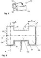
- FIG. 1 shows first an H-paving stone 10 in its basic design, from which in a conventional manner, a composite or laying package of nested paving stones can be made.
- the paving stone 10 has a walkable or passable trained top 12 and the top 12 facing away, i. in the installed state the underside facing the bottom 14.
- the top 12 and the bottom 14 are connected by a peripheral, substantially linearly extending therebetween edge 16 with each other.
- the top 12 - and generally also the bottom 14 - has a substantially H-shaped basic shape, best seen in plan, as in FIG FIG. 2 illustrated.
- This basic H-shape is composed of a first section 18a, a second section 18b and a third section 18c.
- the first and second sections 18a, 18b are substantially rectangular in shape, substantially parallel to each other, and substantially aligned in a first direction A.
- the third portion 18c connects the first and second portions 18a, 18b to each other, is also substantially rectangular in shape, is disposed substantially centrally with the first and second portions 18a, 18b in the first direction A, and is substantially in a second direction B. aligned.
- the first direction A and the second direction B are substantially perpendicular to each other.
- a plurality of protrusions 22 are provided along the periphery of the paving stone 10. These projections 22 are integrally formed on the edge 16 of the paving stone 10 and extend substantially perpendicular to the top 12, ie substantially parallel to the direction of connection between the top 12 and the bottom 14 or substantially in the height direction of the paving stone 10. In one embodiment, these projections 22 extend approximately from the bottom 14 of the paving stone 10th at least over half the height, preferably about 50-90 or even 95%, more preferably about 60-85% towards the top 14 of the paving stone 10.
- FIG. 1A A possible shape and distribution of the projections 22 at the edges 16 of the paving stone 10 is in Figure 1A can be seen, in which the height h of the paving stone 10 is located.
- the projections 22 are each beveled at their the top 12 of the paving stone 10 facing ends, these ends may have different curves. Due to the spacing of the projections 22 from the top 12 of the paving stone 10, these are hidden by the joint filling and are no longer visible to the viewer in the finished composite.
- FIG. 1B shows a variant of this paving stone 10 with two openings 13 in the region of the middle third portion 18c extending from the top 12 to the bottom 14 of the paving stone. Through these openings 13, the paving stone 10 can also be used as a lawn stone. In addition, it has a lighter weight and an improved infiltration of rainwater.
- profilings 15 or the like may be provided, which may change, for example, the design of the paving stone 10 and thus the entire composite of paving stones.
- At least one such projection 22 is provided on the inner flanks 20 of the first and second portions 18a, 18b of the paving stone 10, preferably at least two such projections 22 are provided.
- two adjacent projections 22 in the region of the underside 14 of the paving stone 10 are connected to each other via a web. Then a projection 22 of the adjacent paving stone 10, which is positioned between the two projections 22, abuts against this web. In this way, a desired joint width f can be ensured.
- the projections 22 are offset on the inner flanks 20 at two adjacent paving stones 10 to each other and at a close distance from each other. In this way, the projections 22 on the inner flanks 20 in the first direction A interlock. In the second direction B, the mutual toothing is achieved by the shape of the paving stones 10.
- the widths b of the first and second sections 18a, 18b in the second direction B and the depth d of the projections 22 on the inner flanks 20 and possibly on the first direction A extending edge portions of the first and second portions 18a, 18b be selected so that the projections 22 interlock at the inner edges 20 of two adjacent paving stones 10 in one another and thus prevent mutual displacement of these adjacent paving stones 10 in the first direction A.
- the paving stones 10 can therefore not be pushed together in the first direction A to form a composite. Instead, the paving stones 10 must be lifted into one another in this first direction A and subsequently form a composite of paving stones 10 which can not be detached either in the first direction A or in the second direction B.
- the formation of the association is in FIG. 3 illustrated.
- the paving stones 10 can either be spent loose to the site and laid there to composite or previously combined into so-called laying packages before they are laid on the construction site with suitable laying machines for the final composite.
- FIG. 3A First, some paving stones 10 are pushed together in the second direction B to a row. As in FIG. 3B the rows of paving stones 10 thus formed can be pushed together in the first direction A only until their corners or their projections 22 closest to the corners abut one another. Now these rows of paving stones 10 in the first direction A must be raised into each other, as in FIG. 3C shown to form the composite. In the FIGS. 3A to 3C shown operations can be done either manually and / or by machine. A laying package produced in this way comprises, for example, four rows each with four paving stones 10.
- projections 22 are provided on the edge portions of the first and second portions 18a, 18b extending in the first direction A and also on the edge portions of the first, second and third portions 18a, 18b, 18c extending in the second direction B. intended.
- the projections 22 on the inner flanks 20 of the first and second sections 18a, 18b are absolutely necessary for the inventive toothing of adjacent paving stones 10 for stable bonding. This is exemplary in FIG. 5 illustrated as a third embodiment.
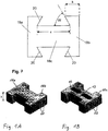
- FIG. 4 shows a section of a thus produced laying package or composite of paving 10.
- edge region of the laying package or curbs are used 11, which can be regarded as half, in the middle of the third portion 18c divided paving stones 10 of the invention.
- Such a curb 11 is also in again Fig. 4A individually illustrated.
- FIG. 5 Now, a second embodiment of a paving stone according to the invention will be described in more detail.
- the same or similar components are again with the same reference numerals as in the above-described provided first embodiment.
- the projections 22 in the illustration of FIG. 5 been omitted.
- FIG. 5 is different from the ones in the Figures 2 and 6 illustrated embodiments in that the angle W, the inner flanks 20 of the first and second portions 18a, 18b include with the connecting portion 18c, each selected greater than 90 degrees.
- this angle W is about 120 degrees.
- this angle W is in the range of about 90 degrees to about 150 degrees, preferably from about 105 degrees to about 135 degrees.
- the mutual interlocking between adjacent paving stones 10 is achieved solely by their basic shape.
- the provision of projections 22 on the inner flanks 20 of the first and second sections 18a, 18b is not absolutely necessary for this purpose.
- paving stone also be provided with integrally formed on the edge 16 projections 22.
- These projections 22 can optionally on the inner flanks 20 of the first and second portions 18a, 18b, on the edge portions of the first and second portions 18a, 18b extending in the first direction A and / or on the edge portions extending in the second direction B. of the first, second and third sections 18a, 18b, 18c.
- the width c of the recess between the first and second portions 18a, 18b is greater than the sum of the widths b of the first portion 18a and the second portion 18b.
- width c of the recess at the boundary to the third portion 18 c and the widths b of the first and second portions 18 a, 18 b can be measured at the outer edges to obtain the largest dimensions.
- the smallest dimensions can be used, ie the width c of the recess at the outer edge of the paving stone 10 and the widths b of the first and second sections 18a, 18b at the level of the flank of the third section 18c.
- a determination of all widths b and c midway between the flank of the third section 18c and the outer edges of the first and second sections 18a, 18b is conceivable.
- flanks of the connecting third section 18c of the paving stone were aligned substantially parallel to one another and substantially parallel to the second direction B, it is also possible to make at least one of the two flanks of the third section 18c at an angle to the second direction B. This angle is for example in the range of about 2 to 5 degrees.
Landscapes
- Engineering & Computer Science (AREA)
- Architecture (AREA)
- Civil Engineering (AREA)
- Structural Engineering (AREA)
- Road Paving Structures (AREA)
Claims (12)
- Pavé (10) pour la formation d'un ensemble d'une pluralité de tels pavés, avec un côté supérieur (12) accessible ou praticable, un côté inférieur (14) éloigné du côté supérieur et un bord (16) s'étendant entre le côté supérieur et le côté inférieur,
dans lequel le côté supérieur (12) présente une forme de base sensiblement en forme de H, se composant d'une première et d'une deuxième section (18a, 18b) sensiblement rectangulaire qui s'étendent espacées l'une de l'autre et sensiblement parallèlement l'une à l'autre et sont orientées dans une première direction (A), ainsi qu'une troisième section (18c) sensiblement rectangulaire qui relie la première et la deuxième section sensiblement perpendiculairement l'une à l'autre et est orientée dans une seconde direction (B) qui s'étend sensiblement perpendiculairement à la première direction (A),
dans lequel des flancs intérieurs (20) de la première et de la deuxième section (18a, 18b) qui sont tournées vers la troisième section (18c), forment avec celle-ci un angle prédéterminé (W),
caractérisé en ce que
dans la zone de chaque flanc intérieur (20) de la première et de la deuxième section (18a, 18b), au moins une saillie (22) est prévue, laquelle est formée sur le bord (16) du pavé (10) sensiblement perpendiculairement au côté supérieur (12),
dans lequel une profondeur (d) des saillies (22) s'élève parallèlement au côté supérieur (12) du pavé (10) de plus d'une moitié d'une largeur de joint (f) entre deux pavés (10) contigus dans l'ensemble,
et en ce que des largeurs (b) de la première et de la deuxième section (18a, 18b) sur le bord éloigné de la troisième section (18c) dans la seconde direction (B), la profondeur (d) et un positionnement des saillies (22) ainsi que l'angle (W) entre les flancs intérieurs (20) de la première et de la deuxième section (18a, 18b) et la troisième section (18c) sont choisis de telle manière que dans la première direction (A), des pavés (10) contigus ne puissent être rassemblés dans la première direction (A) pour former l'ensemble. - Pavé selon la revendication 1,
caractérisé en ce que
l'angle (W) entre les flancs intérieurs (20) de la première et de la deuxième section (18a, 18b) et la troisième section (18c) s'élève sensiblement à 90 degrés. - Pavé selon la revendication 1,
caractérisé en ce que
l'angle (W) entre les flancs intérieurs (20) de la première et de la deuxième section (18a, 18b) et la troisième section (18c) se trouve dans la plage d'environ 90 degrés jusqu'à environ 150 degrés. - Pavé selon l'une des revendications 1 à 3,
caractérisé en ce que
le pavé (10) est pourvu de saillies (22) seulement sur les flancs intérieurs (20) de la première et de la deuxième section (18a, 18b). - Pavé selon l'une des revendications 1 à 3,
caractérisé en ce que
le pavé (10) est pourvu de saillies (22) seulement sur les flancs intérieurs (20) de la première et de la deuxième section (18a, 18b) ainsi que sur les sections de bord s'étendant dans la première direction (A) de la première et de la deuxième section (18a, 18b). - Pavé selon l'une des revendications 1 à 3,
caractérisé en ce que
le pavé (10) est pourvu de saillies (22) sur les flancs intérieurs (20) de la première et de la deuxième section (18a, 18b) sur les sections de bord s'étendant dans la première direction (A) de la première et de la deuxième section (18a, 18b) ainsi que sur les sections de bord s'étendant dans la seconde direction (B) de la première, deuxième et troisième sections (18a, 18b, 18c). - Pavé selon l'une des revendications précédentes,
caractérisé en ce que
la profondeur (d) des saillies (22) s'élève dans la plage d'environ 60 % à environ 90 % de la largeur de joint (f) entre deux pavés contigus (10) dans l'ensemble. - Pavé selon l'une des revendications précédentes,
caractérisé en ce que
les saillies (22) sont espacées du côté supérieur (12) du pavé (10). - Pavé selon l'une des revendications précédentes,
caractérisé en ce que
dans la zone de la première, de la deuxième et/ou de la troisième section (18a, 18b, 18c) est prévue au moins une interruption (13) qui s'étend du côté supérieur (12) au côté inférieur (14) du pavé (10). - Ensemble d'une pluralité de pavés (10) selon l'une des revendications 1 à 9, dans lequel les pavés sont posés dans une orientation sensiblement identique les uns aux autres et sont rassemblés dans la seconde direction (B) et sont levés l'un dans l'autre dans la première direction (A).
- Procédé de fabrication d'un kit de pose de plusieurs pavés avec les étapes consistant à :fabriquer plusieurs pavés (10) selon l'une des revendications 1 à 9 ;rassembler plusieurs de ces pavés (10) dans la seconde direction (B) en une rangée ; etlever l'un dans l'autre au moins deux des rangées ainsi rassemblées de pavés (10) dans la première direction (A).
- Pavé selon la revendication 11,
caractérisé en ce que
le levage l'un dans l'autre des pavés (10) est réalisé mécaniquement.
Applications Claiming Priority (1)
| Application Number | Priority Date | Filing Date | Title |
|---|---|---|---|
| DE102010005018A DE102010005018A1 (de) | 2010-01-19 | 2010-01-19 | Pflasterstein und Verbund von Pflastersteinen |
Publications (3)
| Publication Number | Publication Date |
|---|---|
| EP2354306A2 EP2354306A2 (fr) | 2011-08-10 |
| EP2354306A3 EP2354306A3 (fr) | 2015-06-03 |
| EP2354306B1 true EP2354306B1 (fr) | 2017-09-06 |
Family
ID=43875255
Family Applications (1)
| Application Number | Title | Priority Date | Filing Date |
|---|---|---|---|
| EP11000226.8A Active EP2354306B1 (fr) | 2010-01-19 | 2011-01-13 | Pavé et ensemble de pavés |
Country Status (2)
| Country | Link |
|---|---|
| EP (1) | EP2354306B1 (fr) |
| DE (1) | DE102010005018A1 (fr) |
Families Citing this family (3)
| Publication number | Priority date | Publication date | Assignee | Title |
|---|---|---|---|---|
| DE102011101821A1 (de) | 2010-07-09 | 2012-03-08 | Urs Gassmann | Eckausgleich-Profil |
| DE102015015987A1 (de) | 2015-12-10 | 2017-06-14 | Detlef Schröder | Pflasterstein und hieraus hergestellter Pflasterverband |
| DE102019008497A1 (de) * | 2019-12-09 | 2021-06-10 | Detlef Schröder | H-förmiger Pflasterstein |
Family Cites Families (9)
| Publication number | Priority date | Publication date | Assignee | Title |
|---|---|---|---|---|
| DE3142745A1 (de) * | 1981-10-28 | 1983-05-11 | Couwenbergs, Paul, Dr., 7500 Karlsruhe | "bauelement" |
| DE9408693U1 (de) * | 1994-05-27 | 1994-09-01 | Hagedorn Wolfram | Pflasterelement aus verdichteten Kunststoffabfällen, Kunststoffen und Kunststoffmischungen verschiedenster Art |
| DE29501168U1 (de) * | 1995-01-26 | 1995-08-24 | Eurecast Recycling Anlagen Sys | Selbstverriegelndes Verbundpflaster |
| DE29508723U1 (de) | 1995-05-26 | 1996-09-26 | Kwade Betonwerk Gmbh & Co Kg | Pflasterstein |
| DE29518770U1 (de) | 1995-11-27 | 1996-03-07 | Hell Frank | Verbundpflaster |
| DE29603148U1 (de) | 1996-02-22 | 1996-05-15 | Sf Koop Gmbh Beton Konzepte | Bausatz aus Beton-Pflastersteinen |
| DE29619583U1 (de) | 1996-11-14 | 1998-07-02 | Johann Pfennig Gmbh | Pflasterstein aus Beton für sickerfähige Pflasterungen hoher Tragkraft |
| DE20113580U1 (de) | 2001-08-16 | 2001-12-20 | Geiger Peter | Pflasterstein aus Betonwerkstoff |
| DE10330928B4 (de) | 2003-07-08 | 2005-05-25 | Schröder, Harald | Pflasterstein |
-
2010
- 2010-01-19 DE DE102010005018A patent/DE102010005018A1/de not_active Withdrawn
-
2011
- 2011-01-13 EP EP11000226.8A patent/EP2354306B1/fr active Active
Non-Patent Citations (1)
| Title |
|---|
| None * |
Also Published As
| Publication number | Publication date |
|---|---|
| EP2354306A3 (fr) | 2015-06-03 |
| EP2354306A2 (fr) | 2011-08-10 |
| DE102010005018A1 (de) | 2011-07-21 |
Similar Documents
| Publication | Publication Date | Title |
|---|---|---|
| EP1105576B1 (fr) | Pierre a pave | |
| EP0648291B1 (fr) | Pave avec elements d'espacement lateraux | |
| EP0424592B1 (fr) | Pierres autobloquantes | |
| EP0791689B1 (fr) | Pierre artificielle pour renforcer les aires de circulation à l'extérieur | |
| DE60119990T2 (de) | Pflasterstein | |
| WO2002063100A1 (fr) | Elements de revetement de sol en pierre artificielle | |
| WO2001094703A1 (fr) | Pierre artificielle permettant de fixer des surfaces de circulation exterieures | |
| EP0016353B1 (fr) | Ensemble d'éléments de construction pour ériger des structures tridimensionnelles | |
| EP2354306B1 (fr) | Pavé et ensemble de pavés | |
| DE102009015019A1 (de) | Pflastersteinbausatz zur Erstellung eines Segmentbogenpflasters | |
| EP1024226B1 (fr) | Pierre artificielle pour revêtements | |
| AT403389B (de) | Pflasterstein in rechteckiger form | |
| DE10033267A1 (de) | Betonpalisade | |
| DE202017105303U1 (de) | Rasenstegplatte | |
| DE19960320A1 (de) | Pflastersteinsystem | |
| DE1951581A1 (de) | Verbundstein fuer Vertikal- und doppelten Horizontalverbund | |
| DE19704280A1 (de) | Pflasterstein und Verbund von Pflastersteinen | |
| EP1685299B1 (fr) | Unite de pose en pierres artificielles munie d'evidements sur au moins deux cotes | |
| DE202023002316U1 (de) | Betonpflasterstein | |
| DE202022000899U1 (de) | Betonpflasterstein | |
| DE102020113136A1 (de) | Verschiebeschutzvorrichtung für Flächenbelagelemente und Flächenbelagelement mit einer solchen Verschiebeschutzvorrichtung | |
| DE1119315B (de) | Pflasterstein aus Beton od. dgl. mit zur Verzahnung dienenden Ausnehmungen und Vorspruengen | |
| WO2020109513A1 (fr) | Composant, ensemble d'au moins trois composants de ce type et élément de bord | |
| EP0927792A2 (fr) | Elément de pavage | |
| WO2010034418A1 (fr) | Pavage de sol constitué de blocs moulés |
Legal Events
| Date | Code | Title | Description |
|---|---|---|---|
| PUAI | Public reference made under article 153(3) epc to a published international application that has entered the european phase |
Free format text: ORIGINAL CODE: 0009012 |
|
| AK | Designated contracting states |
Kind code of ref document: A2 Designated state(s): AL AT BE BG CH CY CZ DE DK EE ES FI FR GB GR HR HU IE IS IT LI LT LU LV MC MK MT NL NO PL PT RO RS SE SI SK SM TR |
|
| AX | Request for extension of the european patent |
Extension state: BA ME |
|
| PUAL | Search report despatched |
Free format text: ORIGINAL CODE: 0009013 |
|
| AK | Designated contracting states |
Kind code of ref document: A3 Designated state(s): AL AT BE BG CH CY CZ DE DK EE ES FI FR GB GR HR HU IE IS IT LI LT LU LV MC MK MT NL NO PL PT RO RS SE SI SK SM TR |
|
| AX | Request for extension of the european patent |
Extension state: BA ME |
|
| RIC1 | Information provided on ipc code assigned before grant |
Ipc: E01C 5/00 20060101AFI20150427BHEP |
|
| 17P | Request for examination filed |
Effective date: 20150930 |
|
| RBV | Designated contracting states (corrected) |
Designated state(s): AL AT BE BG CH CY CZ DE DK EE ES FI FR GB GR HR HU IE IS IT LI LT LU LV MC MK MT NL NO PL PT RO RS SE SI SK SM TR |
|
| GRAP | Despatch of communication of intention to grant a patent |
Free format text: ORIGINAL CODE: EPIDOSNIGR1 |
|
| INTG | Intention to grant announced |
Effective date: 20170328 |
|
| GRAS | Grant fee paid |
Free format text: ORIGINAL CODE: EPIDOSNIGR3 |
|
| GRAA | (expected) grant |
Free format text: ORIGINAL CODE: 0009210 |
|
| AK | Designated contracting states |
Kind code of ref document: B1 Designated state(s): AL AT BE BG CH CY CZ DE DK EE ES FI FR GB GR HR HU IE IS IT LI LT LU LV MC MK MT NL NO PL PT RO RS SE SI SK SM TR |
|
| REG | Reference to a national code |
Ref country code: GB Ref legal event code: FG4D Free format text: NOT ENGLISH |
|
| REG | Reference to a national code |
Ref country code: CH Ref legal event code: EP Ref country code: AT Ref legal event code: REF Ref document number: 926070 Country of ref document: AT Kind code of ref document: T Effective date: 20170915 |
|
| REG | Reference to a national code |
Ref country code: IE Ref legal event code: FG4D Free format text: LANGUAGE OF EP DOCUMENT: GERMAN |
|
| REG | Reference to a national code |
Ref country code: DE Ref legal event code: R096 Ref document number: 502011012931 Country of ref document: DE |
|
| REG | Reference to a national code |
Ref country code: NL Ref legal event code: MP Effective date: 20170906 |
|
| REG | Reference to a national code |
Ref country code: LT Ref legal event code: MG4D |
|
| PG25 | Lapsed in a contracting state [announced via postgrant information from national office to epo] |
Ref country code: LT Free format text: LAPSE BECAUSE OF FAILURE TO SUBMIT A TRANSLATION OF THE DESCRIPTION OR TO PAY THE FEE WITHIN THE PRESCRIBED TIME-LIMIT Effective date: 20170906 Ref country code: FI Free format text: LAPSE BECAUSE OF FAILURE TO SUBMIT A TRANSLATION OF THE DESCRIPTION OR TO PAY THE FEE WITHIN THE PRESCRIBED TIME-LIMIT Effective date: 20170906 Ref country code: HR Free format text: LAPSE BECAUSE OF FAILURE TO SUBMIT A TRANSLATION OF THE DESCRIPTION OR TO PAY THE FEE WITHIN THE PRESCRIBED TIME-LIMIT Effective date: 20170906 Ref country code: NO Free format text: LAPSE BECAUSE OF FAILURE TO SUBMIT A TRANSLATION OF THE DESCRIPTION OR TO PAY THE FEE WITHIN THE PRESCRIBED TIME-LIMIT Effective date: 20171206 Ref country code: SE Free format text: LAPSE BECAUSE OF FAILURE TO SUBMIT A TRANSLATION OF THE DESCRIPTION OR TO PAY THE FEE WITHIN THE PRESCRIBED TIME-LIMIT Effective date: 20170906 |
|
| PG25 | Lapsed in a contracting state [announced via postgrant information from national office to epo] |
Ref country code: LV Free format text: LAPSE BECAUSE OF FAILURE TO SUBMIT A TRANSLATION OF THE DESCRIPTION OR TO PAY THE FEE WITHIN THE PRESCRIBED TIME-LIMIT Effective date: 20170906 Ref country code: RS Free format text: LAPSE BECAUSE OF FAILURE TO SUBMIT A TRANSLATION OF THE DESCRIPTION OR TO PAY THE FEE WITHIN THE PRESCRIBED TIME-LIMIT Effective date: 20170906 Ref country code: ES Free format text: LAPSE BECAUSE OF FAILURE TO SUBMIT A TRANSLATION OF THE DESCRIPTION OR TO PAY THE FEE WITHIN THE PRESCRIBED TIME-LIMIT Effective date: 20170906 Ref country code: BG Free format text: LAPSE BECAUSE OF FAILURE TO SUBMIT A TRANSLATION OF THE DESCRIPTION OR TO PAY THE FEE WITHIN THE PRESCRIBED TIME-LIMIT Effective date: 20171206 Ref country code: GR Free format text: LAPSE BECAUSE OF FAILURE TO SUBMIT A TRANSLATION OF THE DESCRIPTION OR TO PAY THE FEE WITHIN THE PRESCRIBED TIME-LIMIT Effective date: 20171207 |
|
| PG25 | Lapsed in a contracting state [announced via postgrant information from national office to epo] |
Ref country code: NL Free format text: LAPSE BECAUSE OF FAILURE TO SUBMIT A TRANSLATION OF THE DESCRIPTION OR TO PAY THE FEE WITHIN THE PRESCRIBED TIME-LIMIT Effective date: 20170906 |
|
| PG25 | Lapsed in a contracting state [announced via postgrant information from national office to epo] |
Ref country code: CZ Free format text: LAPSE BECAUSE OF FAILURE TO SUBMIT A TRANSLATION OF THE DESCRIPTION OR TO PAY THE FEE WITHIN THE PRESCRIBED TIME-LIMIT Effective date: 20170906 Ref country code: RO Free format text: LAPSE BECAUSE OF FAILURE TO SUBMIT A TRANSLATION OF THE DESCRIPTION OR TO PAY THE FEE WITHIN THE PRESCRIBED TIME-LIMIT Effective date: 20170906 Ref country code: PL Free format text: LAPSE BECAUSE OF FAILURE TO SUBMIT A TRANSLATION OF THE DESCRIPTION OR TO PAY THE FEE WITHIN THE PRESCRIBED TIME-LIMIT Effective date: 20170906 |
|
| PG25 | Lapsed in a contracting state [announced via postgrant information from national office to epo] |
Ref country code: SK Free format text: LAPSE BECAUSE OF FAILURE TO SUBMIT A TRANSLATION OF THE DESCRIPTION OR TO PAY THE FEE WITHIN THE PRESCRIBED TIME-LIMIT Effective date: 20170906 Ref country code: IS Free format text: LAPSE BECAUSE OF FAILURE TO SUBMIT A TRANSLATION OF THE DESCRIPTION OR TO PAY THE FEE WITHIN THE PRESCRIBED TIME-LIMIT Effective date: 20180106 Ref country code: EE Free format text: LAPSE BECAUSE OF FAILURE TO SUBMIT A TRANSLATION OF THE DESCRIPTION OR TO PAY THE FEE WITHIN THE PRESCRIBED TIME-LIMIT Effective date: 20170906 Ref country code: IT Free format text: LAPSE BECAUSE OF FAILURE TO SUBMIT A TRANSLATION OF THE DESCRIPTION OR TO PAY THE FEE WITHIN THE PRESCRIBED TIME-LIMIT Effective date: 20170906 Ref country code: SM Free format text: LAPSE BECAUSE OF FAILURE TO SUBMIT A TRANSLATION OF THE DESCRIPTION OR TO PAY THE FEE WITHIN THE PRESCRIBED TIME-LIMIT Effective date: 20170906 |
|
| REG | Reference to a national code |
Ref country code: DE Ref legal event code: R097 Ref document number: 502011012931 Country of ref document: DE |
|
| REG | Reference to a national code |
Ref country code: DE Ref legal event code: R082 Ref document number: 502011012931 Country of ref document: DE Representative=s name: PAGE, WHITE & FARRER GERMANY LLP, DE Ref country code: DE Ref legal event code: R082 Ref document number: 502011012931 Country of ref document: DE |
|
| REG | Reference to a national code |
Ref country code: DE Ref legal event code: R082 Ref document number: 502011012931 Country of ref document: DE Representative=s name: PAGE, WHITE & FARRER GERMANY LLP, DE |
|
| PLBE | No opposition filed within time limit |
Free format text: ORIGINAL CODE: 0009261 |
|
| STAA | Information on the status of an ep patent application or granted ep patent |
Free format text: STATUS: NO OPPOSITION FILED WITHIN TIME LIMIT |
|
| PG25 | Lapsed in a contracting state [announced via postgrant information from national office to epo] |
Ref country code: DK Free format text: LAPSE BECAUSE OF FAILURE TO SUBMIT A TRANSLATION OF THE DESCRIPTION OR TO PAY THE FEE WITHIN THE PRESCRIBED TIME-LIMIT Effective date: 20170906 |
|
| 26N | No opposition filed |
Effective date: 20180607 |
|
| PG25 | Lapsed in a contracting state [announced via postgrant information from national office to epo] |
Ref country code: SI Free format text: LAPSE BECAUSE OF FAILURE TO SUBMIT A TRANSLATION OF THE DESCRIPTION OR TO PAY THE FEE WITHIN THE PRESCRIBED TIME-LIMIT Effective date: 20170906 |
|
| REG | Reference to a national code |
Ref country code: CH Ref legal event code: PL |
|
| GBPC | Gb: european patent ceased through non-payment of renewal fee |
Effective date: 20180113 |
|
| PG25 | Lapsed in a contracting state [announced via postgrant information from national office to epo] |
Ref country code: MT Free format text: LAPSE BECAUSE OF FAILURE TO SUBMIT A TRANSLATION OF THE DESCRIPTION OR TO PAY THE FEE WITHIN THE PRESCRIBED TIME-LIMIT Effective date: 20170906 |
|
| PG25 | Lapsed in a contracting state [announced via postgrant information from national office to epo] |
Ref country code: FR Free format text: LAPSE BECAUSE OF NON-PAYMENT OF DUE FEES Effective date: 20180131 Ref country code: LU Free format text: LAPSE BECAUSE OF NON-PAYMENT OF DUE FEES Effective date: 20180113 |
|
| REG | Reference to a national code |
Ref country code: IE Ref legal event code: MM4A |
|
| REG | Reference to a national code |
Ref country code: FR Ref legal event code: ST Effective date: 20180928 |
|
| REG | Reference to a national code |
Ref country code: BE Ref legal event code: MM Effective date: 20180131 |
|
| PG25 | Lapsed in a contracting state [announced via postgrant information from national office to epo] |
Ref country code: BE Free format text: LAPSE BECAUSE OF NON-PAYMENT OF DUE FEES Effective date: 20180131 Ref country code: LI Free format text: LAPSE BECAUSE OF NON-PAYMENT OF DUE FEES Effective date: 20180131 Ref country code: GB Free format text: LAPSE BECAUSE OF NON-PAYMENT OF DUE FEES Effective date: 20180113 Ref country code: CH Free format text: LAPSE BECAUSE OF NON-PAYMENT OF DUE FEES Effective date: 20180131 |
|
| PG25 | Lapsed in a contracting state [announced via postgrant information from national office to epo] |
Ref country code: IE Free format text: LAPSE BECAUSE OF NON-PAYMENT OF DUE FEES Effective date: 20180113 |
|
| REG | Reference to a national code |
Ref country code: AT Ref legal event code: MM01 Ref document number: 926070 Country of ref document: AT Kind code of ref document: T Effective date: 20180113 |
|
| PG25 | Lapsed in a contracting state [announced via postgrant information from national office to epo] |
Ref country code: AT Free format text: LAPSE BECAUSE OF NON-PAYMENT OF DUE FEES Effective date: 20180113 |
|
| PG25 | Lapsed in a contracting state [announced via postgrant information from national office to epo] |
Ref country code: MC Free format text: LAPSE BECAUSE OF FAILURE TO SUBMIT A TRANSLATION OF THE DESCRIPTION OR TO PAY THE FEE WITHIN THE PRESCRIBED TIME-LIMIT Effective date: 20170906 |
|
| PG25 | Lapsed in a contracting state [announced via postgrant information from national office to epo] |
Ref country code: TR Free format text: LAPSE BECAUSE OF FAILURE TO SUBMIT A TRANSLATION OF THE DESCRIPTION OR TO PAY THE FEE WITHIN THE PRESCRIBED TIME-LIMIT Effective date: 20170906 |
|
| PG25 | Lapsed in a contracting state [announced via postgrant information from national office to epo] |
Ref country code: PT Free format text: LAPSE BECAUSE OF FAILURE TO SUBMIT A TRANSLATION OF THE DESCRIPTION OR TO PAY THE FEE WITHIN THE PRESCRIBED TIME-LIMIT Effective date: 20170906 Ref country code: HU Free format text: LAPSE BECAUSE OF FAILURE TO SUBMIT A TRANSLATION OF THE DESCRIPTION OR TO PAY THE FEE WITHIN THE PRESCRIBED TIME-LIMIT; INVALID AB INITIO Effective date: 20110113 |
|
| PG25 | Lapsed in a contracting state [announced via postgrant information from national office to epo] |
Ref country code: CY Free format text: LAPSE BECAUSE OF FAILURE TO SUBMIT A TRANSLATION OF THE DESCRIPTION OR TO PAY THE FEE WITHIN THE PRESCRIBED TIME-LIMIT Effective date: 20170906 Ref country code: MK Free format text: LAPSE BECAUSE OF NON-PAYMENT OF DUE FEES Effective date: 20170906 |
|
| PG25 | Lapsed in a contracting state [announced via postgrant information from national office to epo] |
Ref country code: AL Free format text: LAPSE BECAUSE OF FAILURE TO SUBMIT A TRANSLATION OF THE DESCRIPTION OR TO PAY THE FEE WITHIN THE PRESCRIBED TIME-LIMIT Effective date: 20170906 |
|
| PGFP | Annual fee paid to national office [announced via postgrant information from national office to epo] |
Ref country code: DE Payment date: 20231107 Year of fee payment: 14 |