EP2349566B1 - Mikrofluidikvorrichtung und verfahren zur durchführung von blutgruppenbestimmung und kreuzprobe - Google Patents
Mikrofluidikvorrichtung und verfahren zur durchführung von blutgruppenbestimmung und kreuzprobe Download PDFInfo
- Publication number
- EP2349566B1 EP2349566B1 EP09743983.0A EP09743983A EP2349566B1 EP 2349566 B1 EP2349566 B1 EP 2349566B1 EP 09743983 A EP09743983 A EP 09743983A EP 2349566 B1 EP2349566 B1 EP 2349566B1
- Authority
- EP
- European Patent Office
- Prior art keywords
- channel
- reaction
- fluid
- flow
- antibody
- Prior art date
- Legal status (The legal status is an assumption and is not a legal conclusion. Google has not performed a legal analysis and makes no representation as to the accuracy of the status listed.)
- Active
Links
- 238000000034 method Methods 0.000 title claims description 24
- 238000009582 blood typing Methods 0.000 title description 20
- 238000006243 chemical reaction Methods 0.000 claims description 216
- 239000012530 fluid Substances 0.000 claims description 185
- 239000003153 chemical reaction reagent Substances 0.000 claims description 147
- 239000008280 blood Substances 0.000 claims description 133
- 210000004369 blood Anatomy 0.000 claims description 132
- 230000004520 agglutination Effects 0.000 claims description 94
- 239000000427 antigen Substances 0.000 claims description 71
- 102000036639 antigens Human genes 0.000 claims description 71
- 108091007433 antigens Proteins 0.000 claims description 71
- -1 plasma treatment Substances 0.000 claims description 40
- 239000000758 substrate Substances 0.000 claims description 40
- 238000009736 wetting Methods 0.000 claims description 35
- 238000001514 detection method Methods 0.000 claims description 32
- 230000009977 dual effect Effects 0.000 claims description 25
- 238000009792 diffusion process Methods 0.000 claims description 24
- 238000011144 upstream manufacturing Methods 0.000 claims description 22
- 239000004094 surface-active agent Substances 0.000 claims description 20
- 230000002441 reversible effect Effects 0.000 claims description 18
- 239000000853 adhesive Substances 0.000 claims description 17
- 230000001070 adhesive effect Effects 0.000 claims description 17
- 230000001900 immune effect Effects 0.000 claims description 12
- 239000000080 wetting agent Substances 0.000 claims description 12
- 239000000654 additive Substances 0.000 claims description 11
- 230000001419 dependent effect Effects 0.000 claims description 10
- 230000015572 biosynthetic process Effects 0.000 claims description 9
- 230000004044 response Effects 0.000 claims description 9
- 238000007818 agglutination assay Methods 0.000 claims description 8
- 102000004169 proteins and genes Human genes 0.000 claims description 7
- 108090000623 proteins and genes Proteins 0.000 claims description 7
- 239000011248 coating agent Substances 0.000 claims description 6
- 238000000576 coating method Methods 0.000 claims description 6
- 239000011888 foil Substances 0.000 claims description 5
- 238000004381 surface treatment Methods 0.000 claims description 5
- 230000000996 additive effect Effects 0.000 claims description 4
- 230000000887 hydrating effect Effects 0.000 claims description 4
- 230000005660 hydrophilic surface Effects 0.000 claims description 4
- 230000000813 microbial effect Effects 0.000 claims description 4
- 230000004048 modification Effects 0.000 claims description 4
- 238000012986 modification Methods 0.000 claims description 4
- 230000000541 pulsatile effect Effects 0.000 claims description 4
- 239000011149 active material Substances 0.000 claims description 3
- 238000010348 incorporation Methods 0.000 claims description 3
- 230000000977 initiatory effect Effects 0.000 claims description 3
- 238000010406 interfacial reaction Methods 0.000 claims description 3
- 238000009832 plasma treatment Methods 0.000 claims description 3
- 230000003612 virological effect Effects 0.000 claims description 3
- 230000008878 coupling Effects 0.000 claims description 2
- 238000010168 coupling process Methods 0.000 claims description 2
- 238000005859 coupling reaction Methods 0.000 claims description 2
- 230000003071 parasitic effect Effects 0.000 claims description 2
- 230000035484 reaction time Effects 0.000 claims description 2
- 239000010410 layer Substances 0.000 description 99
- 239000000523 sample Substances 0.000 description 82
- 238000012360 testing method Methods 0.000 description 79
- 239000007788 liquid Substances 0.000 description 51
- 239000002245 particle Substances 0.000 description 49
- 210000004027 cell Anatomy 0.000 description 44
- 239000003292 glue Substances 0.000 description 40
- 229920003023 plastic Polymers 0.000 description 32
- 239000004033 plastic Substances 0.000 description 30
- 238000009826 distribution Methods 0.000 description 26
- 210000002381 plasma Anatomy 0.000 description 23
- 238000003556 assay Methods 0.000 description 22
- 230000004888 barrier function Effects 0.000 description 17
- 230000002209 hydrophobic effect Effects 0.000 description 16
- 210000002966 serum Anatomy 0.000 description 16
- 229920003171 Poly (ethylene oxide) Polymers 0.000 description 15
- 239000011324 bead Substances 0.000 description 14
- 230000002459 sustained effect Effects 0.000 description 14
- 239000011159 matrix material Substances 0.000 description 13
- 238000002156 mixing Methods 0.000 description 13
- 239000004816 latex Substances 0.000 description 12
- 229920000126 latex Polymers 0.000 description 12
- 230000005499 meniscus Effects 0.000 description 12
- 239000012790 adhesive layer Substances 0.000 description 11
- 239000007787 solid Substances 0.000 description 11
- 239000000725 suspension Substances 0.000 description 11
- 239000004820 Pressure-sensitive adhesive Substances 0.000 description 10
- 238000013461 design Methods 0.000 description 10
- 210000003743 erythrocyte Anatomy 0.000 description 10
- 239000000463 material Substances 0.000 description 10
- 230000003287 optical effect Effects 0.000 description 10
- 102000009027 Albumins Human genes 0.000 description 8
- 108010088751 Albumins Proteins 0.000 description 8
- 230000004913 activation Effects 0.000 description 8
- 230000003247 decreasing effect Effects 0.000 description 8
- 235000014113 dietary fatty acids Nutrition 0.000 description 8
- 239000000194 fatty acid Substances 0.000 description 8
- 229930195729 fatty acid Natural products 0.000 description 8
- 238000011049 filling Methods 0.000 description 8
- 238000004519 manufacturing process Methods 0.000 description 8
- 239000000203 mixture Substances 0.000 description 8
- 239000002699 waste material Substances 0.000 description 8
- 239000000910 agglutinin Substances 0.000 description 7
- 230000008105 immune reaction Effects 0.000 description 7
- 239000012528 membrane Substances 0.000 description 7
- 230000003389 potentiating effect Effects 0.000 description 7
- 239000000126 substance Substances 0.000 description 7
- 230000007704 transition Effects 0.000 description 7
- 230000009471 action Effects 0.000 description 6
- 239000006285 cell suspension Substances 0.000 description 6
- 239000000306 component Substances 0.000 description 6
- 239000011162 core material Substances 0.000 description 6
- 230000000694 effects Effects 0.000 description 6
- 238000011068 loading method Methods 0.000 description 6
- 229920000642 polymer Polymers 0.000 description 6
- 230000008569 process Effects 0.000 description 6
- 238000012216 screening Methods 0.000 description 6
- 239000000243 solution Substances 0.000 description 6
- 230000000007 visual effect Effects 0.000 description 6
- XLYOFNOQVPJJNP-UHFFFAOYSA-N water Substances O XLYOFNOQVPJJNP-UHFFFAOYSA-N 0.000 description 6
- 210000000601 blood cell Anatomy 0.000 description 5
- 230000007423 decrease Effects 0.000 description 5
- 150000002148 esters Chemical class 0.000 description 5
- 230000006870 function Effects 0.000 description 5
- 238000011534 incubation Methods 0.000 description 5
- 208000015181 infectious disease Diseases 0.000 description 5
- 229920000139 polyethylene terephthalate Polymers 0.000 description 5
- 239000005020 polyethylene terephthalate Substances 0.000 description 5
- 238000002360 preparation method Methods 0.000 description 5
- 150000003839 salts Chemical class 0.000 description 5
- 230000035945 sensitivity Effects 0.000 description 5
- 238000012546 transfer Methods 0.000 description 5
- 238000003466 welding Methods 0.000 description 5
- XKRFYHLGVUSROY-UHFFFAOYSA-N Argon Chemical compound [Ar] XKRFYHLGVUSROY-UHFFFAOYSA-N 0.000 description 4
- LYCAIKOWRPUZTN-UHFFFAOYSA-N Ethylene glycol Chemical compound OCCO LYCAIKOWRPUZTN-UHFFFAOYSA-N 0.000 description 4
- 239000002202 Polyethylene glycol Substances 0.000 description 4
- 239000004793 Polystyrene Substances 0.000 description 4
- 238000013459 approach Methods 0.000 description 4
- 238000001914 filtration Methods 0.000 description 4
- 239000000499 gel Substances 0.000 description 4
- 230000002706 hydrostatic effect Effects 0.000 description 4
- 238000004848 nephelometry Methods 0.000 description 4
- 239000004417 polycarbonate Substances 0.000 description 4
- 229920000515 polycarbonate Polymers 0.000 description 4
- 229920001223 polyethylene glycol Polymers 0.000 description 4
- 229920002223 polystyrene Polymers 0.000 description 4
- 239000002904 solvent Substances 0.000 description 4
- 238000003860 storage Methods 0.000 description 4
- 238000002235 transmission spectroscopy Methods 0.000 description 4
- FDCJDKXCCYFOCV-UHFFFAOYSA-N 1-hexadecoxyhexadecane Chemical compound CCCCCCCCCCCCCCCCOCCCCCCCCCCCCCCCC FDCJDKXCCYFOCV-UHFFFAOYSA-N 0.000 description 3
- FBPFZTCFMRRESA-FSIIMWSLSA-N D-Glucitol Natural products OC[C@H](O)[C@H](O)[C@@H](O)[C@H](O)CO FBPFZTCFMRRESA-FSIIMWSLSA-N 0.000 description 3
- 206010018910 Haemolysis Diseases 0.000 description 3
- 239000004831 Hot glue Substances 0.000 description 3
- 239000004743 Polypropylene Substances 0.000 description 3
- CZMRCDWAGMRECN-UGDNZRGBSA-N Sucrose Chemical compound O[C@H]1[C@H](O)[C@@H](CO)O[C@@]1(CO)O[C@@H]1[C@H](O)[C@@H](O)[C@H](O)[C@@H](CO)O1 CZMRCDWAGMRECN-UGDNZRGBSA-N 0.000 description 3
- 229930006000 Sucrose Natural products 0.000 description 3
- 208000003441 Transfusion reaction Diseases 0.000 description 3
- 125000000217 alkyl group Chemical group 0.000 description 3
- 239000002280 amphoteric surfactant Substances 0.000 description 3
- 238000007836 assay cartridge Methods 0.000 description 3
- 238000009739 binding Methods 0.000 description 3
- 238000004132 cross linking Methods 0.000 description 3
- 238000000151 deposition Methods 0.000 description 3
- RTZKZFJDLAIYFH-UHFFFAOYSA-N ether Substances CCOCC RTZKZFJDLAIYFH-UHFFFAOYSA-N 0.000 description 3
- 239000011521 glass Substances 0.000 description 3
- 238000010438 heat treatment Methods 0.000 description 3
- 238000003018 immunoassay Methods 0.000 description 3
- 230000005764 inhibitory process Effects 0.000 description 3
- 238000005304 joining Methods 0.000 description 3
- 230000033001 locomotion Effects 0.000 description 3
- 239000000178 monomer Substances 0.000 description 3
- 239000002736 nonionic surfactant Substances 0.000 description 3
- 229910052760 oxygen Inorganic materials 0.000 description 3
- 229920003229 poly(methyl methacrylate) Polymers 0.000 description 3
- 239000004926 polymethyl methacrylate Substances 0.000 description 3
- 229920001155 polypropylene Polymers 0.000 description 3
- 229920001296 polysiloxane Polymers 0.000 description 3
- 229920000136 polysorbate Polymers 0.000 description 3
- 229920001343 polytetrafluoroethylene Polymers 0.000 description 3
- 239000004814 polyurethane Substances 0.000 description 3
- 229920002635 polyurethane Polymers 0.000 description 3
- 238000003825 pressing Methods 0.000 description 3
- 230000000405 serological effect Effects 0.000 description 3
- 239000000600 sorbitol Substances 0.000 description 3
- 239000005720 sucrose Substances 0.000 description 3
- 235000000346 sugar Nutrition 0.000 description 3
- 150000008163 sugars Chemical class 0.000 description 3
- OENHQHLEOONYIE-JLTXGRSLSA-N β-Carotene Chemical compound CC=1CCCC(C)(C)C=1\C=C\C(\C)=C\C=C\C(\C)=C\C=C\C=C(/C)\C=C\C=C(/C)\C=C\C1=C(C)CCCC1(C)C OENHQHLEOONYIE-JLTXGRSLSA-N 0.000 description 3
- VBICKXHEKHSIBG-UHFFFAOYSA-N 1-monostearoylglycerol Chemical compound CCCCCCCCCCCCCCCCCC(=O)OCC(O)CO VBICKXHEKHSIBG-UHFFFAOYSA-N 0.000 description 2
- HBXWUCXDUUJDRB-UHFFFAOYSA-N 1-octadecoxyoctadecane Chemical compound CCCCCCCCCCCCCCCCCCOCCCCCCCCCCCCCCCCCC HBXWUCXDUUJDRB-UHFFFAOYSA-N 0.000 description 2
- 229920002799 BoPET Polymers 0.000 description 2
- 208000035473 Communicable disease Diseases 0.000 description 2
- SRBFZHDQGSBBOR-IOVATXLUSA-N D-xylopyranose Chemical compound O[C@@H]1COC(O)[C@H](O)[C@H]1O SRBFZHDQGSBBOR-IOVATXLUSA-N 0.000 description 2
- 229920002307 Dextran Polymers 0.000 description 2
- 241000588724 Escherichia coli Species 0.000 description 2
- 108010044091 Globulins Proteins 0.000 description 2
- 102000006395 Globulins Human genes 0.000 description 2
- PEDCQBHIVMGVHV-UHFFFAOYSA-N Glycerol Natural products OCC(O)CO PEDCQBHIVMGVHV-UHFFFAOYSA-N 0.000 description 2
- 241000223960 Plasmodium falciparum Species 0.000 description 2
- 239000004698 Polyethylene Substances 0.000 description 2
- 239000004642 Polyimide Substances 0.000 description 2
- 229920001214 Polysorbate 60 Polymers 0.000 description 2
- 241000607142 Salmonella Species 0.000 description 2
- 241000293871 Salmonella enterica subsp. enterica serovar Typhi Species 0.000 description 2
- 241000607768 Shigella Species 0.000 description 2
- FAPWRFPIFSIZLT-UHFFFAOYSA-M Sodium chloride Chemical compound [Na+].[Cl-] FAPWRFPIFSIZLT-UHFFFAOYSA-M 0.000 description 2
- 208000037386 Typhoid Diseases 0.000 description 2
- 239000002253 acid Substances 0.000 description 2
- NIXOWILDQLNWCW-UHFFFAOYSA-N acrylic acid group Chemical class C(C=C)(=O)O NIXOWILDQLNWCW-UHFFFAOYSA-N 0.000 description 2
- 239000004676 acrylonitrile butadiene styrene Substances 0.000 description 2
- 239000002313 adhesive film Substances 0.000 description 2
- 239000012491 analyte Substances 0.000 description 2
- 125000000129 anionic group Chemical group 0.000 description 2
- 229910052786 argon Inorganic materials 0.000 description 2
- 230000009286 beneficial effect Effects 0.000 description 2
- 239000012472 biological sample Substances 0.000 description 2
- 230000017531 blood circulation Effects 0.000 description 2
- 125000002091 cationic group Chemical group 0.000 description 2
- 230000001413 cellular effect Effects 0.000 description 2
- 230000000295 complement effect Effects 0.000 description 2
- 239000002131 composite material Substances 0.000 description 2
- 108010018927 conglutinin Proteins 0.000 description 2
- 238000010276 construction Methods 0.000 description 2
- 229920001577 copolymer Polymers 0.000 description 2
- 230000000881 depressing effect Effects 0.000 description 2
- QCUFYOBGGZSFHY-UHFFFAOYSA-N depsidomycin Chemical compound O=C1C(C(C)C)NC(=O)C(CC(C)C)NC(=O)C(NC(=O)C(NC=O)C(C)CC)C(C)OC(=O)C2CCCNN2C(=O)C(CC(C)C)NC(=O)C2CCCNN21 QCUFYOBGGZSFHY-UHFFFAOYSA-N 0.000 description 2
- 238000003745 diagnosis Methods 0.000 description 2
- 239000004205 dimethyl polysiloxane Substances 0.000 description 2
- 238000005516 engineering process Methods 0.000 description 2
- 230000014509 gene expression Effects 0.000 description 2
- 230000005484 gravity Effects 0.000 description 2
- 230000008588 hemolysis Effects 0.000 description 2
- WGCNASOHLSPBMP-UHFFFAOYSA-N hydroxyacetaldehyde Natural products OCC=O WGCNASOHLSPBMP-UHFFFAOYSA-N 0.000 description 2
- 230000006872 improvement Effects 0.000 description 2
- 238000001746 injection moulding Methods 0.000 description 2
- 208000014674 injury Diseases 0.000 description 2
- 238000002372 labelling Methods 0.000 description 2
- 238000003475 lamination Methods 0.000 description 2
- 230000000670 limiting effect Effects 0.000 description 2
- 201000004792 malaria Diseases 0.000 description 2
- 230000000873 masking effect Effects 0.000 description 2
- 229920001983 poloxamer Polymers 0.000 description 2
- 229920000435 poly(dimethylsiloxane) Polymers 0.000 description 2
- 229920000058 polyacrylate Polymers 0.000 description 2
- 229920000728 polyester Polymers 0.000 description 2
- 229920000573 polyethylene Polymers 0.000 description 2
- 229920001721 polyimide Polymers 0.000 description 2
- 229920000259 polyoxyethylene lauryl ether Polymers 0.000 description 2
- 239000004800 polyvinyl chloride Substances 0.000 description 2
- 229920000915 polyvinyl chloride Polymers 0.000 description 2
- 238000007639 printing Methods 0.000 description 2
- 238000001055 reflectance spectroscopy Methods 0.000 description 2
- 238000000926 separation method Methods 0.000 description 2
- 239000011734 sodium Substances 0.000 description 2
- 229910052708 sodium Inorganic materials 0.000 description 2
- 239000011780 sodium chloride Substances 0.000 description 2
- 159000000000 sodium salts Chemical class 0.000 description 2
- 238000004611 spectroscopical analysis Methods 0.000 description 2
- 230000007480 spreading Effects 0.000 description 2
- 238000003892 spreading Methods 0.000 description 2
- 230000000087 stabilizing effect Effects 0.000 description 2
- 238000011282 treatment Methods 0.000 description 2
- 238000004879 turbidimetry Methods 0.000 description 2
- 201000008297 typhoid fever Diseases 0.000 description 2
- 239000011800 void material Substances 0.000 description 2
- 238000010792 warming Methods 0.000 description 2
- HDTRYLNUVZCQOY-UHFFFAOYSA-N α-D-glucopyranosyl-α-D-glucopyranoside Natural products OC1C(O)C(O)C(CO)OC1OC1C(O)C(O)C(O)C(CO)O1 HDTRYLNUVZCQOY-UHFFFAOYSA-N 0.000 description 1
- JNYAEWCLZODPBN-JGWLITMVSA-N (2r,3r,4s)-2-[(1r)-1,2-dihydroxyethyl]oxolane-3,4-diol Chemical compound OC[C@@H](O)[C@H]1OC[C@H](O)[C@H]1O JNYAEWCLZODPBN-JGWLITMVSA-N 0.000 description 1
- FFJCNSLCJOQHKM-CLFAGFIQSA-N (z)-1-[(z)-octadec-9-enoxy]octadec-9-ene Chemical compound CCCCCCCC\C=C/CCCCCCCCOCCCCCCCC\C=C/CCCCCCCC FFJCNSLCJOQHKM-CLFAGFIQSA-N 0.000 description 1
- OXDXXMDEEFOVHR-CLFAGFIQSA-N (z)-n-[2-[[(z)-octadec-9-enoyl]amino]ethyl]octadec-9-enamide Chemical compound CCCCCCCC\C=C/CCCCCCCC(=O)NCCNC(=O)CCCCCCC\C=C/CCCCCCCC OXDXXMDEEFOVHR-CLFAGFIQSA-N 0.000 description 1
- AJDONJVWDSZZQF-UHFFFAOYSA-N 1-(2,4,4-trimethylpentan-2-yl)-4-[4-(2,4,4-trimethylpentan-2-yl)phenoxy]benzene Chemical compound C1=CC(C(C)(C)CC(C)(C)C)=CC=C1OC1=CC=C(C(C)(C)CC(C)(C)C)C=C1 AJDONJVWDSZZQF-UHFFFAOYSA-N 0.000 description 1
- WSPUEZILVBBOMP-UHFFFAOYSA-N 1-carboxyheptadecyl(trimethyl)azanium;hydroxide Chemical compound [OH-].CCCCCCCCCCCCCCCCC(C(O)=O)[N+](C)(C)C WSPUEZILVBBOMP-UHFFFAOYSA-N 0.000 description 1
- ALVZUTOHJCLGRN-UHFFFAOYSA-N 1-carboxyundecyl(trimethyl)azanium;hydroxide Chemical compound [OH-].CCCCCCCCCCC(C(O)=O)[N+](C)(C)C ALVZUTOHJCLGRN-UHFFFAOYSA-N 0.000 description 1
- JPPRXACMNPYJNK-UHFFFAOYSA-N 1-docosoxydocosane Chemical compound CCCCCCCCCCCCCCCCCCCCCCOCCCCCCCCCCCCCCCCCCCCCC JPPRXACMNPYJNK-UHFFFAOYSA-N 0.000 description 1
- CMCBDXRRFKYBDG-UHFFFAOYSA-N 1-dodecoxydodecane Chemical compound CCCCCCCCCCCCOCCCCCCCCCCCC CMCBDXRRFKYBDG-UHFFFAOYSA-N 0.000 description 1
- JWYVGKFDLWWQJX-UHFFFAOYSA-N 1-ethenylazepan-2-one Chemical class C=CN1CCCCCC1=O JWYVGKFDLWWQJX-UHFFFAOYSA-N 0.000 description 1
- IHJUECRFYCQBMW-UHFFFAOYSA-N 2,5-dimethylhex-3-yne-2,5-diol Chemical compound CC(C)(O)C#CC(C)(C)O IHJUECRFYCQBMW-UHFFFAOYSA-N 0.000 description 1
- 229920000536 2-Acrylamido-2-methylpropane sulfonic acid Polymers 0.000 description 1
- XHZPRMZZQOIPDS-UHFFFAOYSA-N 2-Methyl-2-[(1-oxo-2-propenyl)amino]-1-propanesulfonic acid Chemical class OS(=O)(=O)CC(C)(C)NC(=O)C=C XHZPRMZZQOIPDS-UHFFFAOYSA-N 0.000 description 1
- NECRQCBKTGZNMH-UHFFFAOYSA-N 3,5-dimethylhex-1-yn-3-ol Chemical compound CC(C)CC(C)(O)C#C NECRQCBKTGZNMH-UHFFFAOYSA-N 0.000 description 1
- NUYADIDKTLPDGG-UHFFFAOYSA-N 3,6-dimethyloct-4-yne-3,6-diol Chemical compound CCC(C)(O)C#CC(C)(O)CC NUYADIDKTLPDGG-UHFFFAOYSA-N 0.000 description 1
- 244000215068 Acacia senegal Species 0.000 description 1
- 235000006491 Acacia senegal Nutrition 0.000 description 1
- RZVAJINKPMORJF-UHFFFAOYSA-N Acetaminophen Chemical compound CC(=O)NC1=CC=C(O)C=C1 RZVAJINKPMORJF-UHFFFAOYSA-N 0.000 description 1
- 101710186708 Agglutinin Proteins 0.000 description 1
- 239000004953 Aliphatic polyamide Substances 0.000 description 1
- VHUUQVKOLVNVRT-UHFFFAOYSA-N Ammonium hydroxide Chemical compound [NH4+].[OH-] VHUUQVKOLVNVRT-UHFFFAOYSA-N 0.000 description 1
- 102100022717 Atypical chemokine receptor 1 Human genes 0.000 description 1
- 230000005653 Brownian motion process Effects 0.000 description 1
- 101100328879 Caenorhabditis elegans col-14 gene Proteins 0.000 description 1
- 229920002284 Cellulose triacetate Polymers 0.000 description 1
- KRKNYBCHXYNGOX-UHFFFAOYSA-K Citrate Chemical compound [O-]C(=O)CC(O)(CC([O-])=O)C([O-])=O KRKNYBCHXYNGOX-UHFFFAOYSA-K 0.000 description 1
- 206010053567 Coagulopathies Diseases 0.000 description 1
- 229920000089 Cyclic olefin copolymer Polymers 0.000 description 1
- 239000004713 Cyclic olefin copolymer Substances 0.000 description 1
- QXNVGIXVLWOKEQ-UHFFFAOYSA-N Disodium Chemical class [Na][Na] QXNVGIXVLWOKEQ-UHFFFAOYSA-N 0.000 description 1
- KCXVZYZYPLLWCC-UHFFFAOYSA-N EDTA Chemical compound OC(=O)CN(CC(O)=O)CCN(CC(O)=O)CC(O)=O KCXVZYZYPLLWCC-UHFFFAOYSA-N 0.000 description 1
- 241001646719 Escherichia coli O157:H7 Species 0.000 description 1
- LFQSCWFLJHTTHZ-UHFFFAOYSA-N Ethanol Chemical compound CCO LFQSCWFLJHTTHZ-UHFFFAOYSA-N 0.000 description 1
- 108010010803 Gelatin Proteins 0.000 description 1
- 229930186217 Glycolipid Natural products 0.000 description 1
- 229920000084 Gum arabic Polymers 0.000 description 1
- 102000018932 HSP70 Heat-Shock Proteins Human genes 0.000 description 1
- 108010027992 HSP70 Heat-Shock Proteins Proteins 0.000 description 1
- 206010067122 Haemolytic transfusion reaction Diseases 0.000 description 1
- 101000678879 Homo sapiens Atypical chemokine receptor 1 Proteins 0.000 description 1
- 101000971879 Homo sapiens Kell blood group glycoprotein Proteins 0.000 description 1
- 101000829958 Homo sapiens N-acetyllactosaminide beta-1,6-N-acetylglucosaminyl-transferase Proteins 0.000 description 1
- 101710146024 Horcolin Proteins 0.000 description 1
- 206010021138 Hypovolaemic shock Diseases 0.000 description 1
- DGAQECJNVWCQMB-PUAWFVPOSA-M Ilexoside XXIX Chemical compound C[C@@H]1CC[C@@]2(CC[C@@]3(C(=CC[C@H]4[C@]3(CC[C@@H]5[C@@]4(CC[C@@H](C5(C)C)OS(=O)(=O)[O-])C)C)[C@@H]2[C@]1(C)O)C)C(=O)O[C@H]6[C@@H]([C@H]([C@@H]([C@H](O6)CO)O)O)O.[Na+] DGAQECJNVWCQMB-PUAWFVPOSA-M 0.000 description 1
- 102100021447 Kell blood group glycoprotein Human genes 0.000 description 1
- 101710189395 Lectin Proteins 0.000 description 1
- 101710179758 Mannose-specific lectin Proteins 0.000 description 1
- 101710150763 Mannose-specific lectin 1 Proteins 0.000 description 1
- 101710150745 Mannose-specific lectin 2 Proteins 0.000 description 1
- 239000005041 Mylar™ Substances 0.000 description 1
- WHNWPMSKXPGLAX-UHFFFAOYSA-N N-Vinyl-2-pyrrolidone Chemical class C=CN1CCCC1=O WHNWPMSKXPGLAX-UHFFFAOYSA-N 0.000 description 1
- 102100023315 N-acetyllactosaminide beta-1,6-N-acetylglucosaminyl-transferase Human genes 0.000 description 1
- IGFHQQFPSIBGKE-UHFFFAOYSA-N Nonylphenol Natural products CCCCCCCCCC1=CC=C(O)C=C1 IGFHQQFPSIBGKE-UHFFFAOYSA-N 0.000 description 1
- 239000004677 Nylon Substances 0.000 description 1
- 229920003189 Nylon 4,6 Polymers 0.000 description 1
- 229920002257 Plurafac® Polymers 0.000 description 1
- 239000004952 Polyamide Substances 0.000 description 1
- 239000005062 Polybutadiene Substances 0.000 description 1
- 239000004695 Polyether sulfone Substances 0.000 description 1
- 229920001213 Polysorbate 20 Polymers 0.000 description 1
- 239000004372 Polyvinyl alcohol Substances 0.000 description 1
- 208000001647 Renal Insufficiency Diseases 0.000 description 1
- DBMJMQXJHONAFJ-UHFFFAOYSA-M Sodium laurylsulphate Chemical class [Na+].CCCCCCCCCCCCOS([O-])(=O)=O DBMJMQXJHONAFJ-UHFFFAOYSA-M 0.000 description 1
- 208000002152 Splenic rupture Diseases 0.000 description 1
- QAOWNCQODCNURD-UHFFFAOYSA-L Sulfate Chemical class [O-]S([O-])(=O)=O QAOWNCQODCNURD-UHFFFAOYSA-L 0.000 description 1
- HDTRYLNUVZCQOY-WSWWMNSNSA-N Trehalose Natural products O[C@@H]1[C@@H](O)[C@@H](O)[C@@H](CO)O[C@@H]1O[C@@H]1[C@H](O)[C@@H](O)[C@@H](O)[C@@H](CO)O1 HDTRYLNUVZCQOY-WSWWMNSNSA-N 0.000 description 1
- 229920004890 Triton X-100 Polymers 0.000 description 1
- 208000027418 Wounds and injury Diseases 0.000 description 1
- NNLVGZFZQQXQNW-ADJNRHBOSA-N [(2r,3r,4s,5r,6s)-4,5-diacetyloxy-3-[(2s,3r,4s,5r,6r)-3,4,5-triacetyloxy-6-(acetyloxymethyl)oxan-2-yl]oxy-6-[(2r,3r,4s,5r,6s)-4,5,6-triacetyloxy-2-(acetyloxymethyl)oxan-3-yl]oxyoxan-2-yl]methyl acetate Chemical compound O([C@@H]1O[C@@H]([C@H]([C@H](OC(C)=O)[C@H]1OC(C)=O)O[C@H]1[C@@H]([C@@H](OC(C)=O)[C@H](OC(C)=O)[C@@H](COC(C)=O)O1)OC(C)=O)COC(=O)C)[C@@H]1[C@@H](COC(C)=O)O[C@@H](OC(C)=O)[C@H](OC(C)=O)[C@H]1OC(C)=O NNLVGZFZQQXQNW-ADJNRHBOSA-N 0.000 description 1
- KGUHOFWIXKIURA-VQXBOQCVSA-N [(2r,3s,4s,5r,6r)-6-[(2s,3s,4s,5r)-3,4-dihydroxy-2,5-bis(hydroxymethyl)oxolan-2-yl]oxy-3,4,5-trihydroxyoxan-2-yl]methyl dodecanoate Chemical compound O[C@@H]1[C@@H](O)[C@H](O)[C@@H](COC(=O)CCCCCCCCCCC)O[C@@H]1O[C@@]1(CO)[C@@H](O)[C@H](O)[C@@H](CO)O1 KGUHOFWIXKIURA-VQXBOQCVSA-N 0.000 description 1
- WERKSKAQRVDLDW-ANOHMWSOSA-N [(2s,3r,4r,5r)-2,3,4,5,6-pentahydroxyhexyl] (z)-octadec-9-enoate Chemical compound CCCCCCCC\C=C/CCCCCCCC(=O)OC[C@H](O)[C@@H](O)[C@H](O)[C@H](O)CO WERKSKAQRVDLDW-ANOHMWSOSA-N 0.000 description 1
- AXXOOWFDLWASFI-UHFFFAOYSA-N [OH-].[Na].[Na].CCCCCCCCCCCC1=NCC[N+]1(CC(O)=O)CC(O)=O Chemical compound [OH-].[Na].[Na].CCCCCCCCCCCC1=NCC[N+]1(CC(O)=O)CC(O)=O AXXOOWFDLWASFI-UHFFFAOYSA-N 0.000 description 1
- 235000010489 acacia gum Nutrition 0.000 description 1
- 230000001133 acceleration Effects 0.000 description 1
- XECAHXYUAAWDEL-UHFFFAOYSA-N acrylonitrile butadiene styrene Chemical compound C=CC=C.C=CC#N.C=CC1=CC=CC=C1 XECAHXYUAAWDEL-UHFFFAOYSA-N 0.000 description 1
- 229920000122 acrylonitrile butadiene styrene Polymers 0.000 description 1
- 125000002252 acyl group Chemical group 0.000 description 1
- 230000006978 adaptation Effects 0.000 description 1
- 239000002390 adhesive tape Substances 0.000 description 1
- 239000000443 aerosol Substances 0.000 description 1
- 230000002776 aggregation Effects 0.000 description 1
- 238000004220 aggregation Methods 0.000 description 1
- 150000001298 alcohols Chemical class 0.000 description 1
- 229920003231 aliphatic polyamide Polymers 0.000 description 1
- 229920003232 aliphatic polyester Polymers 0.000 description 1
- 150000001336 alkenes Chemical class 0.000 description 1
- 150000003973 alkyl amines Chemical class 0.000 description 1
- 150000005215 alkyl ethers Chemical class 0.000 description 1
- 125000005037 alkyl phenyl group Chemical group 0.000 description 1
- 125000002947 alkylene group Chemical group 0.000 description 1
- HDTRYLNUVZCQOY-LIZSDCNHSA-N alpha,alpha-trehalose Chemical compound O[C@@H]1[C@@H](O)[C@H](O)[C@@H](CO)O[C@@H]1O[C@@H]1[C@H](O)[C@@H](O)[C@H](O)[C@@H](CO)O1 HDTRYLNUVZCQOY-LIZSDCNHSA-N 0.000 description 1
- WYTGDNHDOZPMIW-RCBQFDQVSA-N alstonine Natural products C1=CC2=C3C=CC=CC3=NC2=C2N1C[C@H]1[C@H](C)OC=C(C(=O)OC)[C@H]1C2 WYTGDNHDOZPMIW-RCBQFDQVSA-N 0.000 description 1
- 230000004075 alteration Effects 0.000 description 1
- 150000001412 amines Chemical class 0.000 description 1
- 150000001413 amino acids Chemical class 0.000 description 1
- 239000000908 ammonium hydroxide Substances 0.000 description 1
- 150000003863 ammonium salts Chemical class 0.000 description 1
- 238000004458 analytical method Methods 0.000 description 1
- 208000007502 anemia Diseases 0.000 description 1
- 229920006318 anionic polymer Polymers 0.000 description 1
- 230000009830 antibody antigen interaction Effects 0.000 description 1
- PYMYPHUHKUWMLA-UHFFFAOYSA-N arabinose Natural products OCC(O)C(O)C(O)C=O PYMYPHUHKUWMLA-UHFFFAOYSA-N 0.000 description 1
- 239000012298 atmosphere Substances 0.000 description 1
- QVGXLLKOCUKJST-UHFFFAOYSA-N atomic oxygen Chemical compound [O] QVGXLLKOCUKJST-UHFFFAOYSA-N 0.000 description 1
- 229920005601 base polymer Polymers 0.000 description 1
- SRBFZHDQGSBBOR-UHFFFAOYSA-N beta-D-Pyranose-Lyxose Natural products OC1COC(O)C(O)C1O SRBFZHDQGSBBOR-UHFFFAOYSA-N 0.000 description 1
- 229920001222 biopolymer Polymers 0.000 description 1
- 230000002051 biphasic effect Effects 0.000 description 1
- 229920001400 block copolymer Polymers 0.000 description 1
- 239000012503 blood component Substances 0.000 description 1
- 229910021538 borax Inorganic materials 0.000 description 1
- 238000005537 brownian motion Methods 0.000 description 1
- 230000015556 catabolic process Effects 0.000 description 1
- 238000005119 centrifugation Methods 0.000 description 1
- 230000008859 change Effects 0.000 description 1
- 238000012512 characterization method Methods 0.000 description 1
- 239000003638 chemical reducing agent Substances 0.000 description 1
- 239000003795 chemical substances by application Substances 0.000 description 1
- 230000001427 coherent effect Effects 0.000 description 1
- 230000009137 competitive binding Effects 0.000 description 1
- 230000003750 conditioning effect Effects 0.000 description 1
- 239000012792 core layer Substances 0.000 description 1
- 239000003431 cross linking reagent Substances 0.000 description 1
- 230000005574 cross-species transmission Effects 0.000 description 1
- 125000004122 cyclic group Chemical group 0.000 description 1
- 230000006378 damage Effects 0.000 description 1
- 238000006731 degradation reaction Methods 0.000 description 1
- 230000003111 delayed effect Effects 0.000 description 1
- 230000008021 deposition Effects 0.000 description 1
- 239000003599 detergent Substances 0.000 description 1
- 238000011161 development Methods 0.000 description 1
- 238000010790 dilution Methods 0.000 description 1
- 239000012895 dilution Substances 0.000 description 1
- MWYMHZINPCTWSB-UHFFFAOYSA-N dimethylsilyloxy-dimethyl-trimethylsilyloxysilane Chemical class C[SiH](C)O[Si](C)(C)O[Si](C)(C)C MWYMHZINPCTWSB-UHFFFAOYSA-N 0.000 description 1
- 235000019329 dioctyl sodium sulphosuccinate Nutrition 0.000 description 1
- USIUVYZYUHIAEV-UHFFFAOYSA-N diphenyl ether Chemical compound C=1C=CC=CC=1OC1=CC=CC=C1 USIUVYZYUHIAEV-UHFFFAOYSA-N 0.000 description 1
- YHAIUSTWZPMYGG-UHFFFAOYSA-L disodium;2,2-dioctyl-3-sulfobutanedioate Chemical class [Na+].[Na+].CCCCCCCCC(C([O-])=O)(C(C([O-])=O)S(O)(=O)=O)CCCCCCCC YHAIUSTWZPMYGG-UHFFFAOYSA-L 0.000 description 1
- 238000004090 dissolution Methods 0.000 description 1
- NLEBIOOXCVAHBD-QKMCSOCLSA-N dodecyl beta-D-maltoside Chemical compound O[C@@H]1[C@@H](O)[C@H](OCCCCCCCCCCCC)O[C@H](CO)[C@H]1O[C@@H]1[C@H](O)[C@@H](O)[C@H](O)[C@@H](CO)O1 NLEBIOOXCVAHBD-QKMCSOCLSA-N 0.000 description 1
- 229940079593 drug Drugs 0.000 description 1
- 239000003814 drug Substances 0.000 description 1
- 238000004049 embossing Methods 0.000 description 1
- 238000004945 emulsification Methods 0.000 description 1
- 239000002158 endotoxin Substances 0.000 description 1
- 238000005530 etching Methods 0.000 description 1
- CDRUWFRYULGCMU-UHFFFAOYSA-N ethyl hydrogen sulfate;2-nonylphenol Chemical class CCOS(O)(=O)=O.CCCCCCCCCC1=CC=CC=C1O CDRUWFRYULGCMU-UHFFFAOYSA-N 0.000 description 1
- 238000011156 evaluation Methods 0.000 description 1
- 238000002474 experimental method Methods 0.000 description 1
- 150000004665 fatty acids Chemical class 0.000 description 1
- 150000002191 fatty alcohols Chemical class 0.000 description 1
- 150000002194 fatty esters Chemical class 0.000 description 1
- 210000003754 fetus Anatomy 0.000 description 1
- 230000004907 flux Effects 0.000 description 1
- 238000009472 formulation Methods 0.000 description 1
- 239000012634 fragment Substances 0.000 description 1
- 238000004108 freeze drying Methods 0.000 description 1
- 239000007789 gas Substances 0.000 description 1
- 238000005227 gel permeation chromatography Methods 0.000 description 1
- 229920000159 gelatin Polymers 0.000 description 1
- 239000008273 gelatin Substances 0.000 description 1
- 235000019322 gelatine Nutrition 0.000 description 1
- 235000011852 gelatine desserts Nutrition 0.000 description 1
- 125000005456 glyceride group Chemical group 0.000 description 1
- YQEMORVAKMFKLG-UHFFFAOYSA-N glycerine monostearate Natural products CCCCCCCCCCCCCCCCCC(=O)OC(CO)CO YQEMORVAKMFKLG-UHFFFAOYSA-N 0.000 description 1
- SVUQHVRAGMNPLW-UHFFFAOYSA-N glycerol monostearate Natural products CCCCCCCCCCCCCCCCC(=O)OCC(O)CO SVUQHVRAGMNPLW-UHFFFAOYSA-N 0.000 description 1
- 230000004727 humoral immunity Effects 0.000 description 1
- 230000008348 humoral response Effects 0.000 description 1
- 229920001477 hydrophilic polymer Polymers 0.000 description 1
- 229920001600 hydrophobic polymer Polymers 0.000 description 1
- XLYOFNOQVPJJNP-UHFFFAOYSA-M hydroxide Chemical compound [OH-] XLYOFNOQVPJJNP-UHFFFAOYSA-M 0.000 description 1
- 238000007373 indentation Methods 0.000 description 1
- 230000002458 infectious effect Effects 0.000 description 1
- 238000001802 infusion Methods 0.000 description 1
- 230000003993 interaction Effects 0.000 description 1
- 230000001788 irregular Effects 0.000 description 1
- 201000006370 kidney failure Diseases 0.000 description 1
- 238000012125 lateral flow test Methods 0.000 description 1
- 229920006008 lipopolysaccharide Polymers 0.000 description 1
- 239000006194 liquid suspension Substances 0.000 description 1
- 238000000464 low-speed centrifugation Methods 0.000 description 1
- 125000002960 margaryl group Chemical group [H]C([*])([H])C([H])([H])C([H])([H])C([H])([H])C([H])([H])C([H])([H])C([H])([H])C([H])([H])C([H])([H])C([H])([H])C([H])([H])C([H])([H])C([H])([H])C([H])([H])C([H])([H])C([H])([H])C([H])([H])[H] 0.000 description 1
- 238000005259 measurement Methods 0.000 description 1
- 230000007246 mechanism Effects 0.000 description 1
- 239000002906 medical waste Substances 0.000 description 1
- 229910052751 metal Inorganic materials 0.000 description 1
- 239000002184 metal Substances 0.000 description 1
- 238000000465 moulding Methods 0.000 description 1
- URXNVXOMQQCBHS-UHFFFAOYSA-N naphthalene;sodium Chemical compound [Na].C1=CC=CC2=CC=CC=C21 URXNVXOMQQCBHS-UHFFFAOYSA-N 0.000 description 1
- 210000002445 nipple Anatomy 0.000 description 1
- 150000002825 nitriles Chemical class 0.000 description 1
- GSGDTSDELPUTKU-UHFFFAOYSA-N nonoxybenzene Chemical compound CCCCCCCCCOC1=CC=CC=C1 GSGDTSDELPUTKU-UHFFFAOYSA-N 0.000 description 1
- 239000004745 nonwoven fabric Substances 0.000 description 1
- 125000001400 nonyl group Chemical group [H]C([*])([H])C([H])([H])C([H])([H])C([H])([H])C([H])([H])C([H])([H])C([H])([H])C([H])([H])C([H])([H])[H] 0.000 description 1
- SNQQPOLDUKLAAF-UHFFFAOYSA-N nonylphenol Chemical compound CCCCCCCCCC1=CC=CC=C1O SNQQPOLDUKLAAF-UHFFFAOYSA-N 0.000 description 1
- 229920001778 nylon Polymers 0.000 description 1
- 229940049964 oleate Drugs 0.000 description 1
- 238000005457 optimization Methods 0.000 description 1
- 210000000056 organ Anatomy 0.000 description 1
- RZFODFPMOHAYIR-UHFFFAOYSA-N oxepan-2-one;prop-2-enoic acid Chemical class OC(=O)C=C.O=C1CCCCCO1 RZFODFPMOHAYIR-UHFFFAOYSA-N 0.000 description 1
- 239000001301 oxygen Substances 0.000 description 1
- 230000036961 partial effect Effects 0.000 description 1
- 238000001020 plasma etching Methods 0.000 description 1
- 229920001200 poly(ethylene-vinyl acetate) Polymers 0.000 description 1
- 229920003223 poly(pyromellitimide-1,4-diphenyl ether) Polymers 0.000 description 1
- 229920000548 poly(silane) polymer Polymers 0.000 description 1
- 229920002647 polyamide Polymers 0.000 description 1
- 229920002857 polybutadiene Polymers 0.000 description 1
- 229920001707 polybutylene terephthalate Polymers 0.000 description 1
- 229920006393 polyether sulfone Polymers 0.000 description 1
- 229920005644 polyethylene terephthalate glycol copolymer Polymers 0.000 description 1
- 229920000307 polymer substrate Polymers 0.000 description 1
- 229920005862 polyol Polymers 0.000 description 1
- 229920000098 polyolefin Polymers 0.000 description 1
- 150000003077 polyols Chemical class 0.000 description 1
- 229920000056 polyoxyethylene ether Polymers 0.000 description 1
- 229940051841 polyoxyethylene ether Drugs 0.000 description 1
- 239000000256 polyoxyethylene sorbitan monolaurate Substances 0.000 description 1
- 235000010486 polyoxyethylene sorbitan monolaurate Nutrition 0.000 description 1
- 239000000244 polyoxyethylene sorbitan monooleate Substances 0.000 description 1
- 235000010482 polyoxyethylene sorbitan monooleate Nutrition 0.000 description 1
- 229920002503 polyoxyethylene-polyoxypropylene Polymers 0.000 description 1
- 229920001451 polypropylene glycol Polymers 0.000 description 1
- 229920000053 polysorbate 80 Polymers 0.000 description 1
- 229940068968 polysorbate 80 Drugs 0.000 description 1
- 229940068965 polysorbates Drugs 0.000 description 1
- 239000004810 polytetrafluoroethylene Substances 0.000 description 1
- 239000011118 polyvinyl acetate Substances 0.000 description 1
- 229920002689 polyvinyl acetate Polymers 0.000 description 1
- 229920002451 polyvinyl alcohol Polymers 0.000 description 1
- 235000019422 polyvinyl alcohol Nutrition 0.000 description 1
- 230000037452 priming Effects 0.000 description 1
- 230000000750 progressive effect Effects 0.000 description 1
- SCUZVMOVTVSBLE-UHFFFAOYSA-N prop-2-enenitrile;styrene Chemical compound C=CC#N.C=CC1=CC=CC=C1 SCUZVMOVTVSBLE-UHFFFAOYSA-N 0.000 description 1
- 238000005086 pumping Methods 0.000 description 1
- 230000009257 reactivity Effects 0.000 description 1
- 238000011084 recovery Methods 0.000 description 1
- 230000002829 reductive effect Effects 0.000 description 1
- 238000007430 reference method Methods 0.000 description 1
- 238000005057 refrigeration Methods 0.000 description 1
- 239000011347 resin Substances 0.000 description 1
- 229920005989 resin Polymers 0.000 description 1
- 229910052703 rhodium Inorganic materials 0.000 description 1
- 238000010079 rubber tapping Methods 0.000 description 1
- 238000007789 sealing Methods 0.000 description 1
- 239000013049 sediment Substances 0.000 description 1
- 238000004062 sedimentation Methods 0.000 description 1
- 206010040560 shock Diseases 0.000 description 1
- 238000007086 side reaction Methods 0.000 description 1
- 238000012486 side-by-side testing Methods 0.000 description 1
- 238000004513 sizing Methods 0.000 description 1
- 235000019333 sodium laurylsulphate Nutrition 0.000 description 1
- 235000010339 sodium tetraborate Nutrition 0.000 description 1
- CCGZTJIIHNUAQA-UHFFFAOYSA-M sodium;2-[2-hydroxyethyl-(octadecanoylamino)amino]acetate Chemical compound [Na+].CCCCCCCCCCCCCCCCCC(=O)NN(CCO)CC([O-])=O CCGZTJIIHNUAQA-UHFFFAOYSA-M 0.000 description 1
- DGSDBJMBHCQYGN-UHFFFAOYSA-M sodium;2-ethylhexyl sulfate Chemical class [Na+].CCCCC(CC)COS([O-])(=O)=O DGSDBJMBHCQYGN-UHFFFAOYSA-M 0.000 description 1
- 238000002174 soft lithography Methods 0.000 description 1
- 238000005063 solubilization Methods 0.000 description 1
- 230000007928 solubilization Effects 0.000 description 1
- 238000001179 sorption measurement Methods 0.000 description 1
- 238000005507 spraying Methods 0.000 description 1
- 230000006641 stabilisation Effects 0.000 description 1
- 238000011105 stabilization Methods 0.000 description 1
- 230000003068 static effect Effects 0.000 description 1
- 229920000638 styrene acrylonitrile Polymers 0.000 description 1
- 238000006467 substitution reaction Methods 0.000 description 1
- 229940032085 sucrose monolaurate Drugs 0.000 description 1
- 150000003445 sucroses Chemical class 0.000 description 1
- 150000005846 sugar alcohols Polymers 0.000 description 1
- TYLSDQJYPYQCRK-UHFFFAOYSA-N sulfo 4-amino-4-oxobutanoate Chemical compound NC(=O)CCC(=O)OS(O)(=O)=O TYLSDQJYPYQCRK-UHFFFAOYSA-N 0.000 description 1
- BDHFUVZGWQCTTF-UHFFFAOYSA-M sulfonate Chemical compound [O-]S(=O)=O BDHFUVZGWQCTTF-UHFFFAOYSA-M 0.000 description 1
- 238000003786 synthesis reaction Methods 0.000 description 1
- 238000010998 test method Methods 0.000 description 1
- 229920001169 thermoplastic Polymers 0.000 description 1
- 239000004416 thermosoftening plastic Substances 0.000 description 1
- 230000001052 transient effect Effects 0.000 description 1
- 230000001296 transplacental effect Effects 0.000 description 1
- 238000002054 transplantation Methods 0.000 description 1
- 230000008733 trauma Effects 0.000 description 1
- BSVBQGMMJUBVOD-UHFFFAOYSA-N trisodium borate Chemical compound [Na+].[Na+].[Na+].[O-]B([O-])[O-] BSVBQGMMJUBVOD-UHFFFAOYSA-N 0.000 description 1
- GPRLSGONYQIRFK-MNYXATJNSA-N triton Chemical compound [3H+] GPRLSGONYQIRFK-MNYXATJNSA-N 0.000 description 1
- 125000002948 undecyl group Chemical group [H]C([*])([H])C([H])([H])C([H])([H])C([H])([H])C([H])([H])C([H])([H])C([H])([H])C([H])([H])C([H])([H])C([H])([H])C([H])([H])[H] 0.000 description 1
- 210000004291 uterus Anatomy 0.000 description 1
- 238000005406 washing Methods 0.000 description 1
- 239000002888 zwitterionic surfactant Substances 0.000 description 1
Images


Classifications
-
- G—PHYSICS
- G01—MEASURING; TESTING
- G01N—INVESTIGATING OR ANALYSING MATERIALS BY DETERMINING THEIR CHEMICAL OR PHYSICAL PROPERTIES
- G01N33/00—Investigating or analysing materials by specific methods not covered by groups G01N1/00 - G01N31/00
- G01N33/48—Biological material, e.g. blood, urine; Haemocytometers
- G01N33/50—Chemical analysis of biological material, e.g. blood, urine; Testing involving biospecific ligand binding methods; Immunological testing
- G01N33/53—Immunoassay; Biospecific binding assay; Materials therefor
-
- B—PERFORMING OPERATIONS; TRANSPORTING
- B01—PHYSICAL OR CHEMICAL PROCESSES OR APPARATUS IN GENERAL
- B01L—CHEMICAL OR PHYSICAL LABORATORY APPARATUS FOR GENERAL USE
- B01L3/00—Containers or dishes for laboratory use, e.g. laboratory glassware; Droppers
- B01L3/50—Containers for the purpose of retaining a material to be analysed, e.g. test tubes
- B01L3/502—Containers for the purpose of retaining a material to be analysed, e.g. test tubes with fluid transport, e.g. in multi-compartment structures
- B01L3/5027—Containers for the purpose of retaining a material to be analysed, e.g. test tubes with fluid transport, e.g. in multi-compartment structures by integrated microfluidic structures, i.e. dimensions of channels and chambers are such that surface tension forces are important, e.g. lab-on-a-chip
- B01L3/502769—Containers for the purpose of retaining a material to be analysed, e.g. test tubes with fluid transport, e.g. in multi-compartment structures by integrated microfluidic structures, i.e. dimensions of channels and chambers are such that surface tension forces are important, e.g. lab-on-a-chip characterised by multiphase flow arrangements
- B01L3/502776—Containers for the purpose of retaining a material to be analysed, e.g. test tubes with fluid transport, e.g. in multi-compartment structures by integrated microfluidic structures, i.e. dimensions of channels and chambers are such that surface tension forces are important, e.g. lab-on-a-chip characterised by multiphase flow arrangements specially adapted for focusing or laminating flows
-
- B—PERFORMING OPERATIONS; TRANSPORTING
- B01—PHYSICAL OR CHEMICAL PROCESSES OR APPARATUS IN GENERAL
- B01L—CHEMICAL OR PHYSICAL LABORATORY APPARATUS FOR GENERAL USE
- B01L3/00—Containers or dishes for laboratory use, e.g. laboratory glassware; Droppers
- B01L3/50—Containers for the purpose of retaining a material to be analysed, e.g. test tubes
- B01L3/502—Containers for the purpose of retaining a material to be analysed, e.g. test tubes with fluid transport, e.g. in multi-compartment structures
- B01L3/5027—Containers for the purpose of retaining a material to be analysed, e.g. test tubes with fluid transport, e.g. in multi-compartment structures by integrated microfluidic structures, i.e. dimensions of channels and chambers are such that surface tension forces are important, e.g. lab-on-a-chip
- B01L3/502715—Containers for the purpose of retaining a material to be analysed, e.g. test tubes with fluid transport, e.g. in multi-compartment structures by integrated microfluidic structures, i.e. dimensions of channels and chambers are such that surface tension forces are important, e.g. lab-on-a-chip characterised by interfacing components, e.g. fluidic, electrical, optical or mechanical interfaces
-
- B—PERFORMING OPERATIONS; TRANSPORTING
- B01—PHYSICAL OR CHEMICAL PROCESSES OR APPARATUS IN GENERAL
- B01L—CHEMICAL OR PHYSICAL LABORATORY APPARATUS FOR GENERAL USE
- B01L3/00—Containers or dishes for laboratory use, e.g. laboratory glassware; Droppers
- B01L3/50—Containers for the purpose of retaining a material to be analysed, e.g. test tubes
- B01L3/502—Containers for the purpose of retaining a material to be analysed, e.g. test tubes with fluid transport, e.g. in multi-compartment structures
- B01L3/5027—Containers for the purpose of retaining a material to be analysed, e.g. test tubes with fluid transport, e.g. in multi-compartment structures by integrated microfluidic structures, i.e. dimensions of channels and chambers are such that surface tension forces are important, e.g. lab-on-a-chip
- B01L3/50273—Containers for the purpose of retaining a material to be analysed, e.g. test tubes with fluid transport, e.g. in multi-compartment structures by integrated microfluidic structures, i.e. dimensions of channels and chambers are such that surface tension forces are important, e.g. lab-on-a-chip characterised by the means or forces applied to move the fluids
-
- B—PERFORMING OPERATIONS; TRANSPORTING
- B01—PHYSICAL OR CHEMICAL PROCESSES OR APPARATUS IN GENERAL
- B01L—CHEMICAL OR PHYSICAL LABORATORY APPARATUS FOR GENERAL USE
- B01L3/00—Containers or dishes for laboratory use, e.g. laboratory glassware; Droppers
- B01L3/50—Containers for the purpose of retaining a material to be analysed, e.g. test tubes
- B01L3/502—Containers for the purpose of retaining a material to be analysed, e.g. test tubes with fluid transport, e.g. in multi-compartment structures
- B01L3/5027—Containers for the purpose of retaining a material to be analysed, e.g. test tubes with fluid transport, e.g. in multi-compartment structures by integrated microfluidic structures, i.e. dimensions of channels and chambers are such that surface tension forces are important, e.g. lab-on-a-chip
- B01L3/502738—Containers for the purpose of retaining a material to be analysed, e.g. test tubes with fluid transport, e.g. in multi-compartment structures by integrated microfluidic structures, i.e. dimensions of channels and chambers are such that surface tension forces are important, e.g. lab-on-a-chip characterised by integrated valves
-
- B—PERFORMING OPERATIONS; TRANSPORTING
- B01—PHYSICAL OR CHEMICAL PROCESSES OR APPARATUS IN GENERAL
- B01L—CHEMICAL OR PHYSICAL LABORATORY APPARATUS FOR GENERAL USE
- B01L3/00—Containers or dishes for laboratory use, e.g. laboratory glassware; Droppers
- B01L3/50—Containers for the purpose of retaining a material to be analysed, e.g. test tubes
- B01L3/502—Containers for the purpose of retaining a material to be analysed, e.g. test tubes with fluid transport, e.g. in multi-compartment structures
- B01L3/5027—Containers for the purpose of retaining a material to be analysed, e.g. test tubes with fluid transport, e.g. in multi-compartment structures by integrated microfluidic structures, i.e. dimensions of channels and chambers are such that surface tension forces are important, e.g. lab-on-a-chip
- B01L3/502746—Containers for the purpose of retaining a material to be analysed, e.g. test tubes with fluid transport, e.g. in multi-compartment structures by integrated microfluidic structures, i.e. dimensions of channels and chambers are such that surface tension forces are important, e.g. lab-on-a-chip characterised by the means for controlling flow resistance, e.g. flow controllers, baffles
-
- G—PHYSICS
- G01—MEASURING; TESTING
- G01N—INVESTIGATING OR ANALYSING MATERIALS BY DETERMINING THEIR CHEMICAL OR PHYSICAL PROPERTIES
- G01N33/00—Investigating or analysing materials by specific methods not covered by groups G01N1/00 - G01N31/00
- G01N33/48—Biological material, e.g. blood, urine; Haemocytometers
- G01N33/50—Chemical analysis of biological material, e.g. blood, urine; Testing involving biospecific ligand binding methods; Immunological testing
- G01N33/53—Immunoassay; Biospecific binding assay; Materials therefor
- G01N33/5302—Apparatus specially adapted for immunological test procedures
- G01N33/5304—Reaction vessels, e.g. agglutination plates
-
- G—PHYSICS
- G01—MEASURING; TESTING
- G01N—INVESTIGATING OR ANALYSING MATERIALS BY DETERMINING THEIR CHEMICAL OR PHYSICAL PROPERTIES
- G01N33/00—Investigating or analysing materials by specific methods not covered by groups G01N1/00 - G01N31/00
- G01N33/48—Biological material, e.g. blood, urine; Haemocytometers
- G01N33/50—Chemical analysis of biological material, e.g. blood, urine; Testing involving biospecific ligand binding methods; Immunological testing
- G01N33/80—Chemical analysis of biological material, e.g. blood, urine; Testing involving biospecific ligand binding methods; Immunological testing involving blood groups or blood types or red blood cells
-
- B—PERFORMING OPERATIONS; TRANSPORTING
- B01—PHYSICAL OR CHEMICAL PROCESSES OR APPARATUS IN GENERAL
- B01L—CHEMICAL OR PHYSICAL LABORATORY APPARATUS FOR GENERAL USE
- B01L2200/00—Solutions for specific problems relating to chemical or physical laboratory apparatus
- B01L2200/06—Fluid handling related problems
- B01L2200/0636—Focussing flows, e.g. to laminate flows
-
- B—PERFORMING OPERATIONS; TRANSPORTING
- B01—PHYSICAL OR CHEMICAL PROCESSES OR APPARATUS IN GENERAL
- B01L—CHEMICAL OR PHYSICAL LABORATORY APPARATUS FOR GENERAL USE
- B01L2300/00—Additional constructional details
- B01L2300/06—Auxiliary integrated devices, integrated components
- B01L2300/0627—Sensor or part of a sensor is integrated
-
- B—PERFORMING OPERATIONS; TRANSPORTING
- B01—PHYSICAL OR CHEMICAL PROCESSES OR APPARATUS IN GENERAL
- B01L—CHEMICAL OR PHYSICAL LABORATORY APPARATUS FOR GENERAL USE
- B01L2300/00—Additional constructional details
- B01L2300/08—Geometry, shape and general structure
- B01L2300/0809—Geometry, shape and general structure rectangular shaped
- B01L2300/0816—Cards, e.g. flat sample carriers usually with flow in two horizontal directions
-
- B—PERFORMING OPERATIONS; TRANSPORTING
- B01—PHYSICAL OR CHEMICAL PROCESSES OR APPARATUS IN GENERAL
- B01L—CHEMICAL OR PHYSICAL LABORATORY APPARATUS FOR GENERAL USE
- B01L2300/00—Additional constructional details
- B01L2300/08—Geometry, shape and general structure
- B01L2300/0861—Configuration of multiple channels and/or chambers in a single devices
- B01L2300/0867—Multiple inlets and one sample wells, e.g. mixing, dilution
-
- B—PERFORMING OPERATIONS; TRANSPORTING
- B01—PHYSICAL OR CHEMICAL PROCESSES OR APPARATUS IN GENERAL
- B01L—CHEMICAL OR PHYSICAL LABORATORY APPARATUS FOR GENERAL USE
- B01L2300/00—Additional constructional details
- B01L2300/08—Geometry, shape and general structure
- B01L2300/0887—Laminated structure
-
- B—PERFORMING OPERATIONS; TRANSPORTING
- B01—PHYSICAL OR CHEMICAL PROCESSES OR APPARATUS IN GENERAL
- B01L—CHEMICAL OR PHYSICAL LABORATORY APPARATUS FOR GENERAL USE
- B01L2300/00—Additional constructional details
- B01L2300/16—Surface properties and coatings
- B01L2300/161—Control and use of surface tension forces, e.g. hydrophobic, hydrophilic
-
- B—PERFORMING OPERATIONS; TRANSPORTING
- B01—PHYSICAL OR CHEMICAL PROCESSES OR APPARATUS IN GENERAL
- B01L—CHEMICAL OR PHYSICAL LABORATORY APPARATUS FOR GENERAL USE
- B01L3/00—Containers or dishes for laboratory use, e.g. laboratory glassware; Droppers
- B01L3/50—Containers for the purpose of retaining a material to be analysed, e.g. test tubes
- B01L3/502—Containers for the purpose of retaining a material to be analysed, e.g. test tubes with fluid transport, e.g. in multi-compartment structures
- B01L3/5027—Containers for the purpose of retaining a material to be analysed, e.g. test tubes with fluid transport, e.g. in multi-compartment structures by integrated microfluidic structures, i.e. dimensions of channels and chambers are such that surface tension forces are important, e.g. lab-on-a-chip
- B01L3/502761—Containers for the purpose of retaining a material to be analysed, e.g. test tubes with fluid transport, e.g. in multi-compartment structures by integrated microfluidic structures, i.e. dimensions of channels and chambers are such that surface tension forces are important, e.g. lab-on-a-chip specially adapted for handling suspended solids or molecules independently from the bulk fluid flow, e.g. for trapping or sorting beads, for physically stretching molecules
Definitions
- This invention pertains to devices, apparatus, and methods for potentiation of agglutination reactions and more generally to antigen:antibody reactions in microfluidic devices.
- Antigen:antibody reactions involving agglutination are useful in blood typing, in crossmatching for blood transfusion, and in immunodiagnostic agglutination assays in general.
- Blood in the form of packed erythrocytes or whole blood is often useful in the treatment of trauma, hypovolemic shock, anemia and clotting disorders, and generally requires, at a minimum, characterization of the donor blood so as to match the ABO blood type of the donor and recipient, and more generally requires a crossmatch. This is done to avoid a hemolytic transfusion reaction in which red cells having a major incompatibility antigen are inadvertently administered to a recipient having an antibody to that antigen, and also to avoid the minor side reaction in which a red cell antigen in the recipient's blood is attacked by antibodies in the plasma of the donor. Serious consequences such as kidney failure or splenic rupture can result from a transfusion of mismatched blood.
- Rhesus Rhesus
- D antigen D antigen
- the ABO antigens are glycolipids while Rh antigens are proteins.
- anti-D antibody is relatively uncommon, it has been shown that administration of D-incompatible blood frequently results in formation of antibodies in the recipient that can later cause a major hemolytic reaction upon subsequent transfusion and can also cause injury to a fetus in utero. Therefore, forward D screening is also essential for optimal use of blood bank resources. D antigen screening has been problematic due to the "weak" or "incomplete" characteristics of the antigen or antibody.
- Enclosed devices are taught in US 4756884 to Hillman, which teaches a plastic capillary flow device for detecting antigens in blood samples.
- the devices are constructed of generally poorly hydrophilic plastics such as polyethylene terephthalate glycol (PETG), polyester (Mylar®), polyvinylchloride, polystyrene, polycarbonate, or styrene acrylonitrile, or acrylonitrile-butadiene-styrene (ABS).
- PETG polyethylene terephthalate glycol
- Mylar® polyester
- polyvinylchloride polystyrene
- polycarbonate polystyrene
- ABS acrylonitrile-butadiene-styrene
- argon plasma etching or corona discharge are taught (Col 14; lines 44-65).
- the Hillman devices are generally constructed of layers and are adhered to seal around the edges of the internal channels and chambers by ultrasonic welding. Alternatively, double-sided adhesive tape cut to fit around the channels and chambers is sandwiched between the layers (Col 15, lines 5-57).
- One or more antibody reagents, combined with dissolution agents such as surfactants, polyols, sugars and the like, are supplied in the reaction chamber through which the blood sample flows. As further taught in US 5140161, also to Hillman , these methods detect agglutination by reliance on stoppage of flow as the result of a plugged channel (Col 11; lines 1-13).
- EP 0456699 to Vale describes a similar enclosed plastic device in which reagents for red cell agglutination are impregnated in permeable membranes disposed in reaction chambers and will dissolve when whole blood flows through the reaction chambers. Agglutination is detected by evidence of blockage of flow downstream from the reaction chambers.
- US 2005/041525A1 discloses a microfluidic device in which the mixing of fluids is accomplished by dispensing the liquids into a first chamber to produce combined liquid. The liquids are thereafter discharged through at least one capillary from the first chamber into a second chamber for complete mixing.
- the device was then tilted on end to commence flow and a positive agglutination reaction was evidenced by the gross visual appearance of red cell aggregates in the serpentine channel or by blockage of flow in an optional filter member at the end of the channel.
- the disadvantages are that the blood sample can be tested for only one antigen at a time in this device, that dry reagents cannot be used in the device, and that rivulets tend to form under gravitational flow instead of the liquid smoothly filling the reaction chamber.
- US 6743399 which proposed detection of red cell agglutination by blockage of flow (Col 8-9; lines 63-4).
- WO 2004/065930 to Saltsman which is co-owned by the present Applicant, describes devices for blood typing with three reaction channels for detecting A, B, O and D blood groups simultaneously ( Fig. 6 ) using liquid reagents. Multiple optical viewing areas over the reaction channels allowed the user to type the blood sample by visually detecting agglutinated red cells in a sealed disposable unit. An in-line liquid impermeable barrier was used to prevent escape of the blood sample from the device. Suction pressure generated by a diaphragm pump downstream from the reaction channel was used to draw the blood sample and reagent liquid through the device and into a waste chamber. Thus the device could be operated while flat on a bench and did not require gravity-assisted flow.
- WO 2006/009724 to Saltsman which is also co-owned by the present Applicant, describes devices for blood typing with three channels for detecting A, B, O and D blood groups simultaneously (see Fig. 6 of WO2006/009724 ), using dried reagents placed in the device during manufacture. The dried reagents were first rehydrated before admixture with the blood sample. These devices allowed only for forward blood grouping and not for crossmatching and have not been used for any testing except A, B and D blood agglutinins. Suction pressure generated by a diaphragm pump downstream from the reaction channel was used to draw the blood sample and reagent liquid through the device and into a waste chamber. D antigen testing was found to be generally unreliable in these devices.
- the MDmulticard (Medion Diagnostics, Germany).
- the MDmulticard as described in WO 2005/090970 and US 2007/0248983 is essentially a lateral flow strip method.
- the test requires two extra sample preparation steps: a red cell wash step and a pre-dilution step, both of which slow testing and require skilled technicians. Following preparation of the dilute washed cell suspension, results reportedly are obtained in approximately 5 minutes. As such, the test does not meet the need for more immediate test results. Reagent red cells having a 5 week shelf-life, with refrigeration, are available for reverse typing in this test package.
- the methods of the current invention use whole blood for the testing, speeding time to completed test and permitting direct testing from capillary tubes drawn by fingerstick, for example.
- the present invention suggests a microfluidic cartridge having the features of claim 1, a kit for performing an antigen: antibody agglutination assay according to claim 15, a kit for performing a crossmatch according to claim 16 and a method for performing an antigen: antibody agglutination assay according to claim 17.
- the dependent claims relate to advantageous features and embodiments of the invention.
- a preferred solution to the problem of forward blood typing will use whole blood, eliminating the need for washed cells.
- testing requiring longer than two minutes is problematic. Testing should not require special incubation conditions and testing apparatus. There is also a need for a two minute test that is self-contained so that it can be performed without special equipment or sample preparation.
- Similar devices also may find application in crossmatching of blood donors and recipients prior to transfusion. Other applications are found more generally in agglutination-based immunoassays, such as direct and indirect Coombs testing and in testing for microbial serotypes or humoral responses to infections, for example.
- LFDIs Laminar Fluid Diffusion Interfaces
- a laminar flow reaction channel is provided with at least two intake channels, one for a reagent stream and the other for a sample stream, which contact each other in the laminar flow reaction channel and flow side-by-side in parallel or in anti-parallel directions without turbulent mixing.
- the reaction channel typically has a dimension sufficiently small to induce laminar flow of the streams and a length and interfacial surface area between streams sufficient to allow diffusion of a solute from the sample stream into the reagent stream, or vice versa, diffusion of a reagent from the reagent stream into the sample stream.
- T-Sensor The basis of this device is known as a "T-Sensor” (see for example Hatch A et al. 2001. A rapid diffusion immunoassay in a T-sensor. Nature Biotechnol 19:461-5 ; and US Patent 5716852 , co-assigned), which allows the movement of different fluidic layers next to each other within a channel without mixing other than by diffusion.
- the interfacial diffusion zone is probed generally with a beam of light directed parallel to the interface, typically vertically through the depth of the channel.
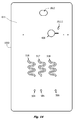
- the two streams flowing next to each other form a concentration gradient of antibody diffusing into the particle stream and particles or aggregates impinging against the antibody stream.
- Increasing the surface area or concentration gradient of this boundary increases the rate of agglutination.
- Agglutination results when particles such as blood cells, including erythrocytes and platelets, or latex particles, for example, are bridgingly crosslinked or otherwise aggregated by formation of antigen:antibody affinity pairs at the interfacial boundary, and appear as clumps of particles that are readily distinguishable to the eye.
- wet-out time the time required for the liquid reagents to wet the channels and flow from an inlet end to an outlet end or to a waste receptacle. Since most channel bodies are plastic, the relative hydrophobicity of the substrate is a factor in determining wet-out time. In the absence of hydrophilic surfaces or surface tension reducers, wet-out time is characteristically irregular and difficult to control. Overcoming the variability in wet-out time leads to improved reproducibility in test results.
- downstream flow control elements By configuring the downstream flow control elements for a passive flow regime with an apparent Reynolds Number in the range of about 0.1 to 10.0 (optimal conditions within this range may depend on factors such as viscosity) and a duration of up to 2 min, agglutination is accelerated and can be readily detected.
- a lower limit was found as flow approaches stagnant or stop flow conditions, resulting in dramatic retardation of agglutination.
- the upper limit is perhaps best determined by practical considerations, the need for economy in sample and reagent consumption and the need to be able to observe the result.
- Duration of flow to endpoint may approach 2 min, but is more preferably achieved in 1 min, and most preferably in less than 30 sec. In some applications, duration of flow is desireable for up to about 10 min.
- Duration is adjusted by configuring the geometry, dimensions, surface properties, and volume of the downstream flow control channel.
- the volume of the downstream flow control channel is generally selected to equal or almost equal the volume of liquid introduced into the assay, thereby ensuring that flow is sustained in the detection window as long as fluid remains in the sample inlets.
- flow becomes driven by capillarity, which can be modulated by selection or treatment of the substrates bordering the channel.
- capillary pressure which increases with decreasing critical dimension, is made to balance viscous drag, which increases with the length of the fluid column but is reduced by the reverse taper of the channel, thereby sustaining flow in a low Reynolds Number laminar flow regime in the detection chamber for an extended duration of flow reaction.
- the method of the invention involves modulating flow rate during the immune binding reaction and agglutination by use of passive capillarity driven flow in a downstream flow control channel for a sustained period of time, generally less than two minutes. After the reaction channel is wetted, flow is slowed and stabilized downstream to form a horizontally-stratified interface, and is then modulated to a transitional low-Reynolds Number flow regime to optimize the immune reaction. This flow regime is sustained for a duration effective in achieving an endpoint.
- Applications of this phenomenon may include, for example, red cell typing of weak or "incomplete” antigens such as “Rhesus” and “weak D” without resort to elevated temperature, use of "conglutinins” (such as albumin, polyethylene glycol, or polyvinylpyrrolidinone), anti-human globulin (AHG), or extended incubation with warming.
- Whole blood may be used for forward typing.
- the availability of blood typing results in less than two minutes has a beneficial impact on the way in which blood donation and transfusion is managed, increasing the efficiency of military and civilian blood banks.
- latex particle agglutination is used.
- Other diagnostic and medical applications are conceived and disclosed here.
- crossmatching between blood donors and blood recipients is performed. Packed red cells from a donor unit and plasma from the intended recipient are added to separate intake channels on a microfluidic cartridge of the present invention and contacted in a horizontally-stratified laminar diffusion interface, with downstream flow control channel to modulate and prolong the flow rate during the immune binding reaction and agglutination. In reactions run for up to ten minutes, agglutination in the presence of a major side incompatibility between blood donor and recipient were readily detected.
- agglutination reactions were also found to be potentiated. These include Coombs testing (direct and indirect) and detection of febrile agglutinins or serotypes of particulate antigens, while not limited thereto.
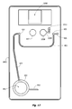
- the invention is a microfluidic cartridge for performing a blood type assay or crossmatch, or an agglutination reaction more generally, having a union or "tee" for contacting a first fluid and a second fluid, the first fluid containing an antigen and the second fluid containing an antibody, in which the fluids are first contacted to form two layers flowing one on top of the other (termed here a "horizontally-stratified laminar fluid diffusion interface") in a reaction channel and then capillary flow is sustained and modulated by prolonging flow in an elongate downstream flow control channel having a microfluidic critical dimension and a reverse taper that broadens from upstream to downstream (ie.
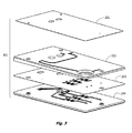
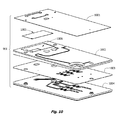
- the microfluidic cartridge includes a) a body member composed of a substrate or substrates and having a reaction channel enclosed therein, the reaction channel having a first end and a second end and having a z-dimension configured for establishing laminar flow conditions; b) a first intake channel for conveying a first fluid and a second intake channel for conveying a second fluid to a staging union fluidly joined to the first end of the reaction channel, where the staging union is configured for synchronizing flow of the two fluids past a pair of capillary stops, one capillary stop for each intake channel; and c) a downstream flow control channel joined to the second end of the reaction channel.
- the downstream flow control channel is configured with broadening taper for modulating capillary flow at low Reynolds Number for a sustained period of time, and is vented downstream.
- the geometry, volume, and surface properties of the downstream flow control channel are optimized for each application.
- the downstream flow control channel can include a throat with flow constrictor for suppressing pulsatile flow in the reaction channel during initial wetting. Wetting is generally initiated by a pulse of suction pressure applied downstream, such as by a finger-operated diaphragm pump with suction stroke.
- Surface properties, geometry and dimensions of the channels are configured to modulate capillary flow at transitional or low Reynolds Number for a sustained period of flow during which agglutination is potentiated.
- An observation window provided on the reaction channel is used to detect agglutination.
- the downstream flow control channel is terminated in a vent or check valve.
- These devices are generally made of plastic and advantageously may be mass produced. Their use in a broad variety of diagnostic and clinical applications is envisaged.
- Microfluidic cartridge a “device”, “card”, or “chip” with internal fluid-handling mesostructures by convention having at least one dimension less than 500 ⁇ m.
- These fluidic structures may include microfluidic channels, chambers, valves, vents, vias, pumps, inlets, nipples, and detection means, for example.
- Microfluidic channel is an enclosed conduit or passage for a fluid having a z-dimension of less than 500 ⁇ m, more preferably less than or about 250 ⁇ m, and most preferably about or less than 150 ⁇ m (about 4 mils), and a cross-sectional area that is broader than deep.
- the most narrow dimension, also termed the "critical dimension", of a channel has the most profound effect on flow, Reynolds Number, pressure drop, and in the devices described here, the most narrow dimension is typically the z-dimension or diameter.
- Microfluidic channels with generally rectangular cross-sections are characterized by x-, y- and z-dimensions.
- the x-dimension is taken as the length "L" of the channel along the axis of flow, the y-dimension as the width and the z-dimension as the depth.
- the channel roof and walls are typically joined by a radius.
- Some microfluidic channels have a circular cross-section and are characterized by a diameter. Other shapes are also possible.
- top, bottom, “upper”, “lower”, “side”, “roof”, “floor”, “base” and “horizontal” as used here are relative terms and do not necessarily describe the orientation of the device or device components in relation to the plane of the earth's surface unless explicitly stated to be so.
- the preferred use of the devices flat on the surface of a table is not intended to be limiting and the z-axis is generally chosen to be perpendicular to the major plane of the device body only as a matter of convenience in explanation and manufacture.
- Bellows Pump is a device formed as a cavity, often cylindrical in shape, covered by an elastomeric, distensible diaphragm, and with an upstream microfluidic channel inlet and a downstream outlet fluidly connected to the cavity.
- a vent as the outlet
- the diaphragm can be pressed down without generating a differential pressure in the cavity, but by then covering the vent and releasing the elastic diaphragm, a suction pressure pulse is generated that finds use in drawing fluid through the inlet microfluidic channel.
- a suction pulse of this kind serves to initiate the assay by initiating fluid flow through a capillary stop; the suction pulse, however, is not required or desired for sustaining fluid flow, which is driven by passive flow capillarity once the upstream microfluidic channel is wetted.
- Foil Pouch an on-board liquid reagent-filled pack or sacculus mounted under an elastic (or deformable) diaphragm, intended to be ruptured when the reagent is needed.
- Elastic diaphragms are readily obtained from polyurethane, polysilicone and polybutadiene, and nitrile for example.
- Deformable, inelastic diaphragms are made with polyethylene terephthalate (PET), mylar, polypropylene, polycarbonate, or nylon, for example.
- PET polyethylene terephthalate
- the reagent pack can be made, for example, by placing a quantity of a liquid between two sheets of a metal-plastic composite and sealing around the edges.
- a "sharp” such as a metal chevron or plastic spike, is place beneath the reagent pack so that pressure on the diaphragm forces the the reagent pack against the sharp and ruptures it.
- Other frangible seals may be employed.
- Such reagent pouches are used to deliver reagents or buffer on command.
- Blister packs for example can include "hydrating buffer reservoirs”.
- Surfactants are amphiphilic molecules that lower the surface and interfacial tensions of a liquid by collecting at the interface, allowing easier spreading on a solid surface and reducing the contact angle.
- Anionic, cationic, zwitterionic, nonionic, and fluorophilic surfactants are contemplated.
- Non-ionic surfactants include polysorbates (e.g., polysorbate 80), polyoxyethylene lauryl ether, n-lauryl- ⁇ -D-maltopyranoside (LM), cetyl ether, stearyl ether, and nonylphenyl ether, Tween® 80, Triton® X-100, and other surfactants.
- nonionic surfactants polyoxyethylene alkyl ether, polyoxyethylene alkyl phenyl ether, polyoxyethylene-polyoxypropylene condensate, acyl polyoxyethylene sorbitan ester, alkyl polyoxyethylene ether, n-dodecyl-.beta.-D-maltoside, sucrose monolaurate, polyoxyethylene lauryl ether, polyoxyethylene alkylene phenyl ether, polyoxyethylene alkylene tribenzyl phenyl ether, polyoxyethylene glycol p-t-octyl phenyl ether, polyoxyethylene higher alcohol ether, polyoxyethylene fatty acid ester, polyoxyethylene sorbitan fatty acid ester, sorbitan fatty acid ester, polyoxyethylene sorbitol fatty acid ester, polyoxyethylene alkylamine, glycerol fatty acid ester, n-octyl-.beta.-D-thioglucoside, cetyl
- nonionic surfactants of this type include Igepal® CO-610 marketed by the GAF Corporation; and Triton® CF-12, X-45, X-114, X-100 and X-102, all marketed by the Rohm and Haas Company; Tergitol® 15-S-9 marketed by the Union Carbide Corporation; PLURAFAC® RA-40 marketed by BASF Corp; Neodol® 23-6.5 marketed by the Shell Chemical Company and Kyro EOB marketed by the Procter & Gamble Company. Amphoteric or zwitterionic surfactants are also useful in providing detergency, emulsification, wetting and conditioning properties.
- amphoteric surfactants include fatty acid amides of amino acids (such as Amisoft® LS-11 and HS-21 made by Ajinomoto), N-coco-3-aminopropionic acid and acid salts, N-tallow-3-iminodiproprionate salts.
- N-lauryl-3-iminodiproprionate disodium salt N-carboxymethyl-N-cocoalkyl-N-dimethylammonium hydroxide, N-carboxymethyl-N-dimethyl-N-(9-octadecenyl)ammonium hydroxide, (1-carboxyheptadecyl)-trimethylammonium hydroxide, (1-carboxyundecyl) trimethylammonium hydroxide, N-cocoamidoethyl-N-hydroxyethylglycine sodium salt, N-hydroxyethyl-N-stearamidoglycine sodium salt, N-hydroxyethyl-N-lauramido-.beta.-alanine sodium salt, N-cocoamido-N-hydroxyethyl-.beta.-alanine sodium salt, as well as mixed alicyclic amines, and their ethoxylated and sulfated sodium salt
- Amine oxide amphoteric surfactants are also useful. This list is by no means exclusive or limiting.
- Surfactants can be added to a reagent to modify the surface tension of the reagent or added to a solid substrate to modify the interfacial tension ⁇ SL of the substrate.
- a surfactant additive a sufficient number of surfactant molecules migrate to the surface of the substrate, a process called "blooming", so as to yield a low contact angle surface. The process is described in US Patent Application 2008/0145280 to Bookbinder .
- Surfactants useful as admixtures with plastics to provide hydrophilic surface properties include polyethylene oxide, polypropylene oxide, nonylphenol ethyoxylate and polyalkylenyeneoxide modified heptamethyltrisiloxane, sodium or ammonium salts of nonyl phenol ethoxyl sulfonic acid, sodium lauryl sulfate, sodium 2-ethylhexyl sulfate and sodium dioctylsulfo succinate, and ionic salts of 2-acrylamido-2-methyl propanesulfonic acid, N-vinyl caprolactam, caprolactone acrylate, N-vinyl pyrrolidone, and sulfate and acrylic monomers, for example.
- Low HLB wetting agents are a subclass of surfactants preferred in the present invention for coating plastic surfaces to decrease contact angle and wet-out time.
- a low HLB wetting agent of the invention can be an anionic, a cationic, a zwitterionic or a non-ionic wetting agent, the latter being preferred. HLB numbers less than or equal to 6 are preferred; wetting agents of this type, when first dried to a surface, are essentially not solubilized when exposed to an aqueous reagent, but can be applied with alcohols, for example.
- the wetting agent of the invention can also be a mixture of two or more wetting agents.
- Candidates include, C12-C20 fatty acid esters of sucrose or xylose, glycerides of sucrose, fatty acid esters of polyoxyethylene, esters of fatty alcohols and polyoxyethylene, esters of sorbitan, esters of polyoxyethylene sorbitan, alcohol-polyglycide esters, and glyceride-polyglycides, also including for example Pluronic® L121, Pluronic® L122, PEO(2) cetyl ether (Brij® 52), PEO(2) stearyl ether (Brij® 72), Sorbitol mono-oleate (Span® 20), Sorbitol tristearate (Span® 65), PEO(200) di-oleate (Maypeg® 200) sorbitol mono-stearate, glycerol mono-stearate, sucrose esters, alkyl naphthalene sodium sulfonate (Alkanol® B), N-octadecyl-dis
- Capillary pressure or "capillary action” describes a pressure or a movement of a liquid under that pressure respectively, also termed “capillarity” , and refers to the tendency of a liquid in a microfluidic channel to advance or recede in a channel so as to minimize the overall surface free energy of the liquid/channel/vapor system. For example, a liquid with a low surface tension will advance to "wet out” a channel made from a material with a high surface energy such as glass. When injected in a microfluidic channel, liquids displaying a concave meniscus will tend to advance in the channel, and liquids displaying a convex meniscus will tend to recede. Thus capillarity is a vectored force resulting in wetting and passive flow of an aqueous liquid in a hydrophilic microfluidic channel.
- Weight time refers to a measurement of the time required for a liquid to advance a standardized length in a microfluidic channel of a given geometry and surface characteristics (generally in mm/s).
- Weight rate refers to an instantaneous rate of advance of a solvent front in a microfluidic channel in units of volume per unit time ( ⁇ L/usec) and can be modulated by surface treatments and by controlling channel geometry. Passive flow driven by downstream wetout can be used to control upstream flow velocity.
- “Creeping flow” versus “low Reynolds Number flow” as defined conventionally is flow where Re is very, very small (generally less than 1) and the inertial effects (momentum, acceleration, and body forces) become negligible in comparison to the viscous resistance. "Creeping flow” transitions at higher Re to the better known “laminar flow”, which of course transitions at much higher fluid velocities to "turbulent” flow. The transition between creeping flow and laminar flow is not sharp, and proceeds gradually through a mixed viscous-inertial regime with increasing role for inertial forces.
- the flow conditions are sometimes termed herein “laminar flow” and other times termed “near-creeping flow”, with the understanding that Re is less than 10, and more preferably less than 5 and most preferably less than 2, but greater than empirically observed inertia-less creeping flow.
- This flow range can also be termed “transitional creeping flow”, “near-laminar flow”, or perhaps more precisely, "low Reynolds Number flow”.
- the low Reynolds Number flow claimed in the invention is associated with an apparent Re in the range of 0.1 to 10 but is not inertia-less. A range of 0.1 to 5 is particularly preferred.
- Re ⁇ 0.01 agglutination was not readily obtained experimentally, affirming the importance of subtle balances of inertial and viscous components of flow in optimizing agglutination under these flow conditions.
- Optical detection can include transmittance and reflectance spectroscopy, turbidimetry (where light is measured at an angle of 180 degrees from incident), nephelometry (where light is measured at 90 degrees from incident, or a some other angle from the incident beam, including forward scattering and back scattering), laser scattering spectroscopy, or visual observation.
- An optical detection window (8) is generally used to evaluate and score the agglutination reaction. This window can include a magnifier if desired. The test may also be automated.
- Laser scattering, turbidimetry, nephelometry, reflectance and transmittance spectroscopy are readily instrumented with LEDs or other light source and with analog or digital circuitry. Instrumentation generally provides improved sensitivity, a wider range, and a more linear response as compared to visual means for detection. For some applications, visual detection means are suitable.
- Fabrication methods include laser stenciling, lamination, embossing, stamping, injection molding, masking, etching, photocatalyzed stereolithography, soft lithography, and so forth, or any combination of the above.
- Each cartridge can be formed of a pair of members or layers glued or fused together, or of a plurality of layers glued or fused together.
- the term "layer” refers to any of one or more generally planar solid substrate members or glue layers comprising a cartridge; "layers” also includes individual sheets, roll stock, and any molded body members formed as generally planar members. Layers may be joined with pressure sensitive adhesive (PSA) or thermal adhesive. Alternatively, they may be fused under pressure with heat, solvent, or by ultrasonic welding. The number of layers in the device will be dependent on the required functionalities and the fabrication process is chosen.
- PSA pressure sensitive adhesive
- thermal adhesive thermal adhesive
- Plastic is a preferred material for building microfluidic devices of the present invention.
- Plastics which may be used include olefins, cyclic polyolefins, cyclic olefin copolymers, polyesters, polyethylene terephthalate, polybutylene terephthalate, polystyrenes, polycarbonates, polypropylene, polyethylene, polyurethane, polyether sulfone, polyvinyl chloride, polyvinyl acetate, polyamides, polyimides, polyacrylate, polymethylmethacrylate (PMMA), polytetrafluoroethylenes, polydimethylsiloxane (PDMS), polysilane, cellulose triacetate, thermoplastics in general, and so forth. Composites and copolymers are also frequently used. The knowledge to select plastics or other solid substrates and conventional adhesives is widely known in related arts.
- planar disposable cartridges of the present invention are generally credit card-sized. Most on-cartridge fluid handling and structural elements have internal dimensions ranging in size from less than 100 ⁇ m to a few mm in size and are designed to handle fluid volumes from a few microliters to a milliliter or two.
- two intake channels (1,2) are joined at a staging union (5).
- a liquid sample is introduced into a first channel; another sample or reagent liquid is introduced into a second channel.
- One sample or reagent will include a particulate suspension.
- an agglutination reaction occurs.
- the appearance of dynamically moving particle aggregates or "clumps" in the optical window (8) typically signals a positive reaction, although competitive binding reactions can also be designed where a positive reaction is signaled by the absence of aggregates.
- the staging union (5) includes a dual capillary stop (6) having two capillary stops stacked on top of each other. With this geometry, fluids can be simultaneously released into a common reaction channel (7) in response to a start signal, the fluids flowing as lamellae, one on top of the other in parallel, and forming a horizontally-stratified laminar fluid diffusion interface (HLFD interface).
- the reaction channel or chamber includes an optical window (8) and an optional delay channel segment (7a).
- the delay channel segment can be compacted as a serpentine channel, for example, and is configured with a length scaled for the desired interfacial reaction time.
- HLFD interface detection segment (7b) is typically characterized by an aspect ratio so that interfacial surface area is optimized relative to the volume.
- a constricted neck or "throat" 17 is formed between the reaction channel (7) with optical window (8) and the downstream flow control channel (10).
- FIG. 1B A sectional view of the staging union (5) is shown schematically in FIG. 1B .
- the two intake channels (1,2) enter the staging union at different levels so that one fluid will emerge on top of the other in the common reaction channel (7a).
- Two capillary stops (21,22) are provided.
- the capillary stops are interposed between the intake channels (1,2) and the staging union (5), and are configured to form a dual capillary stop (6).
- the dual capillary stop (6) illustrates the general principal that an aqueous liquid will not cross a surface energy barrier without an activation energy. Thus a meniscus forms where the channel geometry expands sharply or a hydrophobic barrier surface is formed.
- energy is provided, for example as a suction pulse applied downstream to start the assay, both fluids will simultaneously cross the capillary stop (6) and enter the common reaction channel (7a).
- FIG. 1C A second embodiment of a staging union (5) is shown in FIG. 1C .
- hydrophobic barriers are used to form capillary stops.
- the two intake channels (1,2) enter the staging union at different levels so that one fluid will emerge on top of the other in the common reaction channel (7).
- Two hydrophobic capillary stops (23,24) each comprising a hydrophobic barrier (18,19) are provided.
- the capillary stops are interposed between the intake channels (1,2) and the common reaction channel (7a), and are configured to form a staging union (5) with dual capillary stop (6).
- Fluid contacting the hydrophobic barriers will stop flow until the surface energy of the barrier is overcome, generally when the fluids spill over the barrier in response to a downstream suction pulse, thus synchronizing simultaneous entry of the two input fluids into downstream common reaction channel (7a). In this way the two fluids can be "gated” to enter the downstream reaction channel essentially at the same time.
- downstream flow control channel (10) comprises a throat segment (10a), a runoff segment (10b), and a terminal segment (10c) fluidly joined to a vent, vented manifold, or check valve.
- Downstream flow control channel (10) is configured to optimize the stratified laminar flow regime in the upstream reaction channel so as to potentiate the agglutination reaction.
- Throat segment (10a) is dimensioned to provide relatively high resistance to flow and suppress any transient pressure pulse generated to overcome the capillary stop. Flow in the downstream flow control channel is thus converted to passive "capillary" flow by wetting the throat (10a).
- “Runoff” channel segment (10b) is characterized by diverging lateral walls (11) forming a reverse taper (progressively broadening or increasing in volume and aspect ratio from upstream to downstream) and is wetted by positive capillary pressure.
- the length and volume of the runoff channel (10) is dimensioned so that flow in the upstream reaction channel is sustained at a steady "trickle" at low Reynolds Number for the desired period of time chosen to observe an agglutination reaction.
- Flow resistance in the runoff channel segment (10b) is decreased due to the increasing channel width relative to throat (10a).
- throat 10a had a depth of about 120 um and a width of 200 to 400 um.
- Runoff channel segment (10b) had a depth of about 120 um and the generally rectilinear channel walls (11) diverge to a maximum width of about 2.3 mm.
- the invention is not limited by this example and the geometry is selected to target the desired Reynolds Number. Cylindrical or ovoid cross-sectional channels may also be used. More generally, throat segment (10a) has a constricted cross-sectional area and parallel walls configured for resistively suppressing any pulsatile pressure pulse of a fluid exiting said reaction channel.
- the elongate runoff channel segment (10b) is joined to a downstream end of said throat segment, said runoff channel segment having internal surfaces (16) and diverging "reverse tapered" walls (11) configured for modulating and sustaining passive flow in said reaction channel (7) following wetting of said throat (10a), and an operative connection to a downstream vent.
- the downstream flow control channel (10) is configured to modulate passive flow of said fluid with an apparent Reynolds Number in the range of 0.1 and 10 as determined in said reaction chamber (7b), where the low Reynolds Number flow is sustained for a duration of about 30 seconds to 2 minutes or more.
- a terminal tapered passive flow channel segment (10c) with terminus 12 serves to join common reaction channel 7 and downstream flow control channel 10 to a vent (14) where air can be displaced as fluid fills the system.
- the walls of segment 10c may converge to join vent 14 or a manifold with a common vent.
- Parallel, multiplex reaction channels 7 and flow control channels 10 may share a common vent to atmosphere and common branching inlet channels.
- Check valves may also be used.
- the vent is configured as a capillary stop.
- Vent (14) may include a check valve, a liquid-gas filter barrier, or may be manually operated. Either a suction pressure pulse or positive pressure pulse may be used to generate a start signal, overcoming the paired capillary stops and initiating fluid flow in the reaction channel. A chemical or electrical change that modifies the surface energy barrier may also be used.
- two fluids are introduced into separate inlets (3,4) in the cartridge and joined at a common union (5) with the reaction channel (7).
- a suction pressure pulse is used to initiate flow, overcoming dual capillary stop (6). Because of the microfluidic dimensions of the reaction channel (7) and low Reynolds Number, the fluids flowing in parallel form a horizontally-stratified laminar fluid diffusion interface. Diffusion between the two fluid lamellae results in an immune reaction.
- Intake channel substrate surfaces 15 may be selected or treated so that when contacted with a fluid, a desired contact angle is obtained.
- Downstream channel substrate surfaces 16 may also be selected or treated so that when contacted with a fluid, a desired contact angle is obtained.
- a whole blood sample stream and a hydrated antibody reagent stream are introduced at staging junction (5) into a common microfluidic reaction channel (7) and flow in parallel as stacked, stratified layers until they exit the channel.
- the two streams form an HLFD interface characterized by a sharp concentration gradient of antibody diffusing into the particle stream and particles or aggregates sedimenting or impinging on the basis of their Stokes radius into the antibody stream.
- Agglutination of red cells by antibodies is used to identify the red cell blood type. Dynamic moving aggregates of red cells are detected in optical window (8).
- the sample stream is a stream of latex particles or concentrated blood corpuscles such as platelets.
- the reagent stream is generally an antibody; however the roles may be reversed.
- the antibody may be an analyte of the sample stream and the reagent stream may be a particle suspension. Again, antibody diffuses into the particle stream and particles mix by Brownian motion (for particles smaller than a few microns apparent diameter) or flocculate as aggregates.
- both streams are aqueous and have Newtonian flow characteristics. Mean diffusional path lengths are typically under 100 ⁇ m.
- one fluid is a biological sample and the other fluid is an immunological reagent; in other embodiments, both fluids are biological samples, as in crossmatching donor and recipient blood samples.
- Immunological reagents may include antibody, antigen, antibody to a blood group, antigen to a febrile antibody, antibody to a febrile antigen, antibody to a protein, antibody to an antibody, antibody to a microbial antigen, antibody to a parasitic antigen, or antibody to a viral antigen, while not limited thereto.
- Optical detection can include transmittance spectroscopy, nephelometry, laser scattering spectroscopy, for example, or visual observation.
- Particles are generally in the range of 40 nm to 10 ⁇ m apparent diameter and may be, for example, latex particles. Cells such as tanned erythrocytes and platelets may also be used.
- a viewing or detection window (8) is generally used to evaluate and score the agglutination reaction.
- This window can include a magnifier if desired, and can be designed to permit digital photography of the result for permanent record of the test.
- the test may also be automated. Laser scattering, nephelometry and transmittance spectroscopy are readily instrumented with LEDs and analog or digital circuitry. Optical scanning is also useful to detect optical bar codes on the cartridge, which may be linked to sample identifiers so that the test result is transferred to an electronic medical record if desired.
- the test is performed without instrumentation and the result is read visually; a visually detectable endpoint is provided, generally in less than 2 minutes, more preferably less than 1 minute, and most preferably in about 30 seconds or less. In other embodiments, the endpoint may be read at up to 10 min following start of the reaction.
- Downstream flow control channel (10) with constricting throat (10a) and reverse tapered runoff channel segment (10b) has been found to potentiate conditions for detection of agglutination in the upstream reaction channel (7). Contrary to the teachings of the prior art, optimal conditions for detection are created by sustained flow modulated at a low Reynolds Number in the HLFD interface detection zone (7b).
- a Horizontally-Stratified Laminar Fluid Diffusion Interface is formed when two streams are contacted with each other downstream from the staging union under conditions in which a horizontally-stratified low-Reynolds Number flow regime is established, one stream flowing on top of the other.
- Intake channels for conveying a sample stream and a reagent stream are joined at a common union to a microfluidic reaction channel in such a way that the two fluids flow in the reaction channel as stratified layers one on top of the other.
- the fluids flow in parallel in the reaction channel, forming a generally coherent interface dominated by diffusional mixing.
- the "L” dimension is the length of the channel and is typically designed to provide a residence time sufficient for effective progress of the interfacial reaction between the two streams.
- Lengthening and folding channel (7a) serves to increase the residence time while compacting the size of the device (ie. providing a "delay" segment).
- performance of an HLFD interface is improved by downstream modulation of the Reynolds Number in the reaction channel.
- Passive flow conditions are used. Once passive wetting of the downstream flow control channel (10) begins, the flow rate, linear velocity and Reynolds Number conditions in the upstream reaction channel or chamber are driven by the rate of wetting downstream.
- the wet-out rate ( ⁇ L/ ⁇ sec) can be ramped up or down by modifying the design or surface properties of the downstream channel to optimize the formation of immune complexes in the upstream reaction channel or viewing chamber.
- passive downstream control of flow parameters at the HLFD interface increases the sensitivity and speed of an agglutination reaction.
- the sustained duration of low Reynolds Number flow is also useful in eliciting agglutination in some instances.
- a preferred flow regime is characterized by 0.1 ⁇ Re ⁇ 10, a range covering the transition from creeping flow to laminar flow ("low Reynolds Number laminar flow"); where viscous forces can be expected to dominate inertial forces. Optimization of flow velocity or flow rate in this range is dependent on factors such as viscosity and surface tension. Estimates of linear velocity associated with potentiated agglutination are in the range of 2- 20 mm/s for a more viscous fluid such as blood and 4 - 40 mm/s for a less viscous fluid such as water. Flow velocities of less than 0.02 mm/s were not associated with successful potentiation of agglutination. These flow parameters are given for the reaction channel (7) but are dependent on the configuration of geometry and surface energy of the downstream flow control channel (10).
- cartridges of the present invention are made of plastics, a relatively low surface energy substrate. Lower surface energy substrates are wetted more poorly compared to higher energy substrates.
- a commonly used index of wettability is contact angle ⁇ , usually measured with pure water or a reference liquid.
- poly(methyl methacrylate) has a relatively high critical surface tension compared to poly(tetrafluoroethylene), 39 versus 18 dynes/cm respectively.
- Glass in contrast, has a relatively high critical surface tension of 170 dynes/cm. Representative values are shown in Table 1.
- the fluid will generally form a concave meniscus and experiences a pressure or force causing it to advance along the channel, wetting the wall surfaces.
- the rate of flow of the fluid is dependent on the relative strength of P CAP and P DRAG , where P CAP is the capillary pressure or "capillarity" and P DRAG is the resistance to flow or "viscous impedance”.
- the relative force or pressure ratio of P CAP and P DRAG is used to modulate passive flow.
- One form of modulation of the wet-out rate is dependent on the geometry of the downstream flow control channel, the other on the surface properties.
- Geometry of channel (10) is a factor in reducing or increasing the ratio of capillarity to drag.
- a section of channel with diverging lateral walls ie. a "runoff” or “spreading” channel
- a section of channel with converging or narrow walls ie a "constricting” channel
- Ramp up and ramp down of flow rates can be obtained in this way while maintaining laminar flow conditions at a selected Reynolds Number or range of Reynolds Numbers in the upstream HLFD interface.
- the z-dimension of the flow control channel is held constant and the width of the channel is varied, although it can readily be seen that the z-dimension may be modified with similar effect.
- the wetting force is increased but the drag increases by a cubic exponent. Wall smoothness is also a factor.
- the length and volume of the downstream flow control channel also determines the duration of flow; passive flow at low Re for a duration of about 2 min, more preferably 1 min, and most preferably about 30 seconds, has been found useful to detect agglutination reactions.
- downstream flow control channel Passive flow in the downstream flow control channel is sustained until the excess upstream liquid volume is emptied or until capillary force no longer overcomes resistance.
- a downstream capillary stop may be used to terminate flow and prevent fluids from contacting the downstream vent, eliminating the need for a hydrophobic barrier filter in the device such as taught by Saltsman (US 2004/065930 ).
- the surface properties of channel (10) are also factors in reducing or increasing the ratio of capillarity to drag.
- Surface properties of substrates (15,16) can be modified by the selection of plastics, by the choice of adhesives, by surface treatment, or by incorporation of additives into the plastic or adhesive.
- Plasma treatment, or coating, texturing, impregnating and/or covalently attaching a hydrophilic surface active material such as a wetting agent may be used to decrease contact angle and enhance wetting. Modification of the surface tension of the fluid is also useful.
- plastic substrates formulated with hydrophilic additives are used to make these devices. Addition of a hydrophilic additive increases the surface energy of the plastic.
- U.S. Pat. No. 3,686,355 describes a block copolymer of a base polymer with a second surface modifying additive.
- U.S. Pat. Nos. 5,354,815 and 5,614,598 describe polymers having enhanced hydrophilicity.
- a hydrophilic polysiloxane anionic polymer is bonded to an aliphatic polyamide or polyester polymer substrate.
- U.S. Pat. No. 4,387,183 describes grafting of hydrophilic chains to a polymer surface to increase the contact angle.
- Plastic body layers are typically joined by pressure sensitive adhesives, hot melt adhesives, transfer adhesives, double-sided adhesives, solvent welding, or ultrasonic welding, and so forth.
- hydrophilic glues applied as a transfer adhesive to a base layer, which is then used to cover and seal a microfluidic channel molded in a facing layer, increases the speed and consistency of flow in the channel.
- the lower contact angle surface of the base layer dominates the wet-out of the molded channel.
- PSA Pressure sensitive adhesives
- a number of U.S. and foreign patents are directed to the use of hydrophilic polymers used to formulate pressure sensitive adhesives. See, for example, U.S.
- a preferred embodiment uses a double sided adhesive (ACA) member to join body layers forming a microfluidic channel.
- ACA double sided adhesive
- the ACA glue layer is not stenciled out and is left exposed to the channel.
- the glue is formulated to form a wettable substrate.
- hydrophilic modified acrylic glues contact angles less than those of the underlying plastic substrate are obtained.
- the higher energy surface of the more hydrophilic glue dominates the wetout of the oppositely facing plastic internal surface of the channel. Wetting agents and concentrations are chosen that do not overcome the excess free energy of the glue/substrate interface necessary for adhesion.
- a single ACA layer adhesively interposed therebetween serves synergically to both join the layers and also to line the channels with a hydrophilic layer, and the critical surface tension or contact angle of the two glue faces of the ACA layer can be adjusted separately.
- Formulating the two ACA glue layers with different combinations of wetting agents results in a novel sandwich design, in which the hydrophilicity of channels facing one side of the glue layer differs from the hydrophilicity of channels facing the other side.
- a fluid in a channel in a base body layer and a fluid in a channel in an upper body layer of a molded device will experience measurably distinct wetting energies. This has proved useful, for example, where one fluid is blood and the other fluid is an aqueous reagent.
- wetting is driven by depositing a matrix material in the intake channels that increases the surface energy of the solid substrate while not dissolving in the fluid.
- the formulations may be applied to the device during assembly by masking, spraying, spotting or printing techniques known in the art and are typically dried in place. Such materials include low HLB wetting agents.
- wetting is driven by depositing a matrix material in a channel that decreases the surface tension of the liquid so that it can more readily advance over a low surface energy substrate.
- the matrix material is typically a surface active agent such as a surfactant, and may include mixtures with a co-surfactant, and is formulated so that it dissolves rapidly in the advancing solvent front of the liquid entering the channel.
- the matrix is applied to the channel during assembly by spotting or printing techniques known in the art and is typically dried in place.
- These fast-dissolving matrices can be formulated from hydrophilic substances such as polymers and sugars, for example.
- Candidate surfactant materials include TritonTM CF-87 (Dow Chemicals).
- wetting properties and channel geometry are also factors in design of inlet ports for sample and reagent loading.
- pipets or capillary tubes are used to load samples or reagents into the inlet ports (3,4) of microfluidic assay cartridges of the present invention.
- On-board liquid reagents are employed in other embodiments, and the reagents must be first released from a foil pouch or other storage container and conveyed to the reaction in an intake channel.
- two intake channels (1,2) are used in the devices of the present invention, one for conveying a sample liquid, the other for conveying a reagent liquid.
- the two intake channels meet at a staging union (5) at the upstream end of the reaction channel (7), as illustrated schematically in FIG. 1 .
- capillarity drives the wetting process.
- the fluid is first loaded in a small receptacle or released into a chamber from a reagent pouch, and from there it is drawn into the microfluidic intake channel or channels.
- Capillarity is sufficient to drive fluid flow in a horizontal microfluidic channel if the viscosity is Newtonian and the contact angle of the substrate (15) favors wetting.
- Capillarity may be used to load aqueous reagents and blood into the intake channels of the devices of the present invention.
- a preferred contact angle for loading aqueous reagents is in the range of 20 to 30°, most preferentially about 28°, but the preferred contact angle for loading whole blood is in the range of 10-20°, most preferentially about 10°.
- an ACA layer formulated with different glue additives on each face is used. The lower number of the range was selected so that the microfluidic channel would readily imbibe the fluid, and the upper number of the range was selected so that the fluid would not flow past capillary stops (21,22,23,24) as discussed further below.
- the contact angles provided above include a compensation factor for dried reagents placed in the microfluidic channel.
- the capillarity of unmodified plastic is not generally in this range, and surface treatments or glue layers are used to modify the substrate to achieve the desired wet-out.
- Capillarity is also useful for stopping flow, a process sometimes termed "pinning the meniscus". Surfaces with low surface energy and high contact angle are used to stop flow, for example by substitution of a more hydrophobic material. Capillarity is also decreased by sharply increasing the wetted wall area of the microfluidic channel ahead of the fluid.
- two separate intake channels are joined to the reaction channel by a staging union (5) with dual paired capillary stop (6).
- the two capillary stops (21,22,23,24) are stacked vertically so that by overcoming the capillary stop in response to a pneumatic pulse, the two streams are brought into flowing contact in union (5) to form a horizontally-stratified laminar fluid diffusion (HLFD) interface, the fluids flowing as stacked lamellae. It is preferred that the fluids not enter the reaction channel one at a time, but rather simultaneously at a time selected by the user.
- both fluids can be loaded into the device prior to starting the assay without spilling into the reaction channel (7).
- the fluids fill the device up to the capillary stops (21,22,23,24) and go no further.
- the surface energy of the geometric or hydrophobic barrier is overcome, and both fluids enter the reaction channel simultaneously.
- the two fluids then will flow one on top of the other and an HLFD interface is rapidly formed in the reaction channel. In this way, the assay start time is initiated by a command action from the user.
- application of the downstream suction pulse is accomplished with a vented diaphragm pump positioned downstream from the reaction channel.
- the suction stroke is the release stroke on the diaphragm, the diaphragm having elastic recovery, during which the vent is closed.
- Momentarily tilting the cartridge or tapping to apply a gravitational or momentum push may also be used.
- Automated and machine driven applications are also conceived.
- Fluid streaming is an uneven velocity profile characterized by streamlining liquid surrounded by larger areas of stagnant flow or bubbles. Streaming in the reaction chamber has the effect of reducing the active interfacial area for the immunological reaction and decreasing sensitivity. Readouts are also less consistent and can be delayed in the presence of streaming. Potentiation of the immunological reaction occurs when the two streams stratify on top of each other as very thin sheets (lamellae) while remaining in motion.
- fluid exiting the reaction chamber was typically emptied into a compactly shaped waste chamber of some kind and the waste chamber was vented, optionally using a hydrophobic liquid-impermeable filter barrier.
- sensitivity of an immune reaction is also a function of the avidity and affinity of the antibody, incubation time, temperature, salt, and concentration of solutes such as proteins and detergents that affect the thickness of the "double-layer" and the zeta potential.
- Particles in colloidal suspension are stabilized by electrostatic repulsion and by the thickness of the double layer, that prevents close approach.
- agglutination has been thought to occur when bivalent or multivalent antibodies bridge the distance between particles and form crosslinks. This agglutination has biphasic kinetics. This kind of agglutination shows a signature bell-shaped curve in response to increasing antibody concentration. Too much antibody saturates the system and inhibits crosslinking.
- FIG. 2 Shown in FIG. 2 is a CAD drawing of an embodiment with body (101) of the current invention for blood typing.
- the device (100) is about 5 x 9 cm and less than 0.5 cm thick.
- the uppermost layer is an appliqué with labelling for performing and scoring the assay, and can optionally include a hinged cover for added space for instructions.
- the body (101) is made of transparent plastic.
- a sample port (103) and a reagent port (104) are shown. Also shown is a viewing window (102) and a priming diaphragm pump (105). Further details are provided in the following figures.
- FIG. 3 is an exploded view of a representative body (101) of FIG. 2 .
- the device as shown here is assembled of four body layers, including coversheet layer (201), upper molded body member (202), ACA glue stencil layer (203), and base molded body layer (204). Details of the microfluidic circuitry are provided in the following figures.
- FIG. 4 is a plan view of the coversheet layer (201) and is labeled to identify the location of the sample well orifice (103), which overlies an inlet cavity in the upper body layer for receiving a sample, and inlet cavity (104) for receiving an immunological reagent.
- the bellows pump assembly also includes finger vent (306) for manually generating a suction stroke and internal fluidic connection to the fluid inlets. By first pressing on the diaphragm and then covering the vent with a finger, then upon releasing the diaphragm a suction pressure differential is created inside the device. A machine operated interface may also be used. This suction pulse initiates wetting and fluid flow into the reaction chambers.
- reaction chambers there are three reaction chambers (701,702,703, FIG. 8 ), although more or fewer may be used.
- the reaction chambers are formed in the molded body members of the device.
- Each reaction chamber includes a viewing window (307,308,309).
- the viewing windows correspond to a channel for A blood group testing (under 307), a channel for B blood group testing (under 308), and a channel for D blood group testing (under 309), respectively.
- FIG. 5 depicts the upper surface of the upper molded body member (202). All features are three-dimensional impressions or cutouts in the plastic surface.
- the bellows pump chamber (401) lies beneath the actuation diaphragm (105) and has a fluidic connection (402) to the finger vent (306) and a second fluidic connection (403) to the reaction channels. Fluidic connection (403) is circuitously routed to vias (404,405 and 406), which connect to the outlet ends of downstream flow control channels 501, 502 and 503 on the backside of the molded part (see FIG. 6 ). Downstream flow control channels 501, 502 and 502 in turn connect to the reaction channels 701, 702 and 703. Therefore, a suction pulse generated in the bellows pump cavity (401) is distributedly transmitted to all the reaction channels in parallel.
- Downstream flow control channels combine a narrow throat segment (501a,502a,503a) and a runoff channel segment (501b,502b,503b).
- the sample well (407) lies beneath the sample inlet orifice (103) and is used to receive a defined sample volume for testing.
- This sample can be a whole blood, plasma, or serum sample, or a cellular or particulate suspension of interest, for example whole blood, as is useful for blood typing.
- a reagent well (408) for receiving a rehydrating reagent solution. Fluid entering the reagent well (408) is distributed into manifold (704 of FIG. 8 , trifurcated) and from there into a plurality of reaction channels (710, 711 and 712).
- FIG. 6 the upper molded body member (202) is again presented, but the drawing represents features on the bottom of the piece seen as if looking through the plastic from above (so that features of all body layer faces depicted in the figures are in registration and fluid paths can be readily traced from layer to layer).
- Vias (404, 405 and 406) connect via distribution manifold 509 downstream flow control channels 501, 502 and 503 with vent line (403) and the bellows pump chamber 401.
- Vias 504, 505, and 506 and 603, 604 and 605 connect the downstream flow control channels with reaction channels 701, 702 and 703 in the base molded body member (204).
- Sample well 407 and reagent well (408) are punched all the way through the upper body member.
- Sample well (407) is fluidly connected to inferior capillary stops (510,511,512) and serpentine channels (516,517,518) via distribution manifold (509) embossed in the bottom of the upper molded body member (202).
- distribution manifold 704 embossed in the top of the base molded body member (204) is fluidly connected to superior capillary stops (713,714,715) and serpentine channels (516,517,518).
- Distribution manifold 509 conveys the sample from the sample well to the reaction channels and distribution manifold 704 conveys the reagent fluid from the reagent distribution chamber to the reaction channels.
- the two fluids, flowing in stratified laminar flow in the reaction channels 701, 702 and 703 establish the HLFD interface.
- FIG. 7 depicts the double-sided ACA glue layer (203) used to join the upper molded body member (202) and the base molded body member (204).
- the glue layer is stencilled, for example with a laser cutter, to remove the glue and core material from vias and passages where the fluid passages of the two molded body members are confluent. Cutouts in the glue layer include the reagent well (408), serpentine channels 516, 517 and 516, and vias (504, 505, 506) for joining the reaction channels 701, 702 and 703 to the downstream flow control channels 501, 502 and 503.
- Glue layer 203 has a top face 611 and a bottom face (not numbered). The contact angle for each glue face can be adjusted individually.
- Reagent well 408 is fluidly connected with manifold 704, which trifurcates, splitting the reagent fluid into three separate branches.
- Each reagent branch can contain a "dried reagent zone" (710, 711, 712), where dried reagents are pre-printed in the device during manufacture. The reagent fluid is used to rehydrate these reagents immediately before use.
- r fluid wetting of dried reagent zones (710, 711 and 712) rehydrates the immunological reagents in each channel, but the fluid is stopped at inferior capillary stops 713, 714 and 715.
- the sample is then added to sample well 407 and wets out manifold 509, also coming to a stop at superior capillary stops 510, 511 and 512.
- Entry of the two fluids into the serpentine channels 516, 517 and 518 requires an activation step in the form of a suction pulse delivered with the aid of bellows pump (105) and associated extensible diaphragm formed by the covering of layer 201 over pump chamber 401.
- the serpentine channels (516,517,518) are embossed in both opposing faces of the upper and base body members and are stenciled in the interposed glue layer.
- the reaction chambers (701,702,703) are formed only in the upper face of the base body member (204).
- the serpentine channel is thus deeper than the reaction channel.
- a z-dimension in the reaction channel of about 120 um is used in this example, although dimensions up to 500 um may have application in the devices of the present invention.
- FIG. 9 Shown in FIG. 9 is a CAD drawing of an embodiment of the current invention for blood typing.
- the device (900) with body (901) is about 5 x 9 cm and less than 0.5 cm thick.
- the uppermost layer is an appliqué with labelling for performing and scoring the assay, and can optionally include a hinged cover for added space for instructions.
- the body (901) is made of transparent plastic.
- Sample inlet (103) and reagent dispensing apparatus (1007) are also shown. Further details are provided in the following figures. Viewing window 102 and bellows pump 105 are as previously described.
- FIG. 10 is an exploded view of a representative body (901) of FIG. 9 .
- the device as shown here is assembled of four body layers, including coversheet layer (1001), upper molded body member (1002), ACA glue stencil layer (1003), and base molded body member (1004).
- coversheet layer (1001) coversheet layer
- upper molded body member (1002) upper molded body member
- ACA glue stencil layer 1003
- base molded body member 1004
- a reagent pouch 1005 that fits in the corresponding cavity (1006) in the upper molded body member (1002). Details of the microfluidic circuitry are provided in the following figures.
- FIG. 11 is a plan view of the coversheet layer (1001) and is labeled to identify the location of the sample well orifice (103), which overlies a cavity in the upper body layer for receiving a sample, and a small vent hole (1010) which is used in dispensing reagent from the reagent pouch (1005).
- Flexible diaphragm (1007) defined by cutouts (1007a,1007b) overlies the reagent pouch (1005) and is used to apply pressure so as to burst the reagent pouch.
- the diaphragm is of the material of the coversheet layer (1001) and is selected for transparency and for a modulus of elasticity appropriate for a hand-operated diaphragm.
- a second diaphragm formed of the coverlayer, the "actuation diaphragm", is part of a bellows pump assembly 105 and overlies the pump cavity 401.
- the bellows pump is used to initiate the assay.
- the bellows pump assembly also includes finger vent (306) and internal fluidic connections to the fluid inlets. By first pressing on the diaphragm and then covering the vent with a finger, then upon releasing the diaphragm a suction pressure differential is created inside the device.
- a machine operated interface could also be used. This suction pulse initiates wetting and fluid flow into the reaction chambers.
- reaction chambers there are three reaction chambers (701,702,703, FIG. 15 ), although more or fewer may be used.
- the reaction chambers are formed in the molded body members of the device.
- Each reaction chamber includes a viewing window (307,308,309) as seen in FIG. 11 .
- the viewing windows correspond to a channel for A blood group testing (under 307), a channel for B blood group testing (under 308), and a channel for D blood group testing (under 309), respectively.
- FIG. 12 depicts the upper surface of the upper molded body member (1002). All features are three-dimensional impressions or cutouts in the plastic surface.
- the bellows pump chamber (401) lies beneath the actuation diaphragm of the pump assembly (105) and has a fluidic connection (402) to a finger vent (306) and a second fluidic connection (403) to a suction pressure pulse distribution channel in turn connected to the downstream termini of the reaction channels.
- Fluidic connection (403) is circuitously routed to vias (404,405 and 406), which connect to the outlet ends of downstream flow control channels 501, 502 and 503 on the backside of the molded part (see FIG. 13 ).
- Downstream flow control channels 501, 502 and 502 in turn connect to the reaction channels 701, 702 and 703 (see FIG . 15 ). Therefore, a suction pulse generated in the bellows pump cavity (401) is synchronously transmitted to all the reaction channels in parallel.
- Downstream flow control channels combine a narrow throat segment (501a,502a,503a) and a runoff channel segment (501b,502b,503b).
- the sample well (407) lies beneath the sample inlet orifice (103) and is used to receive a defined sample volume for testing.
- This sample can be a whole blood, plasma, or serum sample, or a cellular or particulate suspension of interest.
- the reagent distribution chamber (1008) With associated conduit (1009) to via (1011) and vent (1010).
- the reagent distribution chamber is filled passively following rupture of the reagent pouch (1005) and functions to meter the fluid volume dispensed into the system.
- excess reagent begins to exit vent (1010), the operator is instructed to release pressure on the reagent reservoir diaphragm 1007, thus dispensing a defined volume.
- Fluid entering the reagent distribution chamber (1008) is distributed into reagent distribution manifold (704 of FIG. 15 , trifurcated) and from there into a plurality of reaction channels (710, 711 and 712).
- a sculptured cutout for enclosing the reagent pouch 1005. Sloped walls are designed for draining fluid released from the pouch into common reagent channel (1015, FIG. 15 ) and from there through via 1011 and channel 1009 to reagent distribution chamber 1008.
- the cutout 1012 in the ACA glue layer (1003, FIG. 14 ) is provided so that the reagent pouch directly contacts a sharp prominence (1016) in the base molded body member (1004, FIG. 15 ).
- FIG. 13 the upper molded body member (1002) is again presented, but the drawing represents features on the bottom of the piece seen as if looking through the plastic from above (so that features of all body layer faces depicted in the figures are in registration and fluid paths can be readily traced from layer to layer and member to member).
- Vias (404, 405 and 406) connect downstream flow control channels 501, 502 and 503 with vent line (402,403) and the bellows pump chamber 401.
- Vias 504, 505, and 506 and 603, 604 and 605 connect the downstream flow control channels with reaction channels 701, 702 and 703 in the base molded body member (1004).
- Sample well 407 and reagent distribution chamber (408) are punched all the way through the upper body member.
- Sample well (407) is fluidly connected to capillary stops (510,511,512) and serpentine channels (516,517,518) via sample distribution manifold (509) embossed in the bottom of the upper molded body member (1002).
- reagent distribution manifold 704 embossed in the top of the base molded body member (1004) is fluidly connected to capillary stops (713,714,715) and serpentine channels (516,517,518).
- Distribution manifold 509 conveys the sample from the sample well to the reaction channels and distribution manifold 704 conveys the reagent fluid from the reagent distribution chamber to the reaction channels.
- the two fluids, flowing in stratified laminar flow in the reaction channels 701, 702 and 703 establish the HLFD interface.
- FIG. 14 depicts the double-sided ACA glue layer (1003) used to join the upper molded body member (1002) and the base molded body member (1004).
- the glue layer is stencilled, for example with a laser cutter, to remove the glue and core material from vias and passages where the fluid passages of the two molded body members are confluent. Cutouts in the glue layer include via (1011) for joining the reagent common channel (1015) to the reagent distribution chamber (408), serpentine channel 516, 517 and 518 cutouts, and vias (504, 505, 506) for joining the reaction channels 701, 702 and 703 to the downstream flow control channels 501, 502 and 503. Cutout 1012 is placed over the sharp prominence 1016 and removes material which would otherwise shield the reagent pouch 1005 from the sharp 1016.
- Glue layer 1003 has a top face 611 and a bottom face (not shown). The contact angle for each glue face can be adjusted individually.
- FIG. 15 the three dimensional features of the molded base layer (1004) of the device are shown.
- sharp 1016 is used to rupture reagent pouch 1005 and reagent common channel 1015 is used to convey the reagent fluid to the reagent distribution chamber 408.
- Manifold 704 trifurcates, splitting the reagent fluid into three separate branches. Each reagent branch can contain a "dried reagent zone" (710, 711, 712), where dried reagents are pre-printed in the device during manufacture. The reagent fluid is used to rehydrate these reagents immediately before use.
- the serpentine channels (516,517,518) are embossed in the opposing faces of the upper and base body members and are cut out of the interposed glue layer.
- the reaction chambers (701,702,703) are formed only in the base body member.
- the serpentine channel is thus greater in depth than the reaction channel.
- a z-dimension in the reaction channel of about 120 um is used in this example, although dimensions up to 500 um may have application in the devices of the present invention.
- FIGS. 16A and 16B show a schematic in cross-sectional view through the long axis of a device, FIG. 16A representing an upstream portion (1600A) of the device and FIG. 16B representing a downstream portion (1600B) of the device.
- a sample 1601 may be introduced into a sample inlet well (1602) and will fill sample inlet channel or distribution manifold 1603.
- a reagent fluid is shown filling a reagent distribution chamber 1605 and a reagent inlet channel or manifold 1606.
- Dual capillary stop 1610 prevents the two fluid streams from continuing into reaction channel 1611 unless the device is activated by a pressure pulse or by a wetting out of the capillary stops.
- Downstream flow control channel 1612 is elongated (extended in length relative to its width and depth) and continues into the downstream portion (1600B) of the device. Fluid advancing in this microfluidic channel 1612 is governed by a capillary flow force and fluidic resistance and advances at a rate engineered by the geometry and surface energy of the downstream channel 1612.
- Chamber 1613 represents a bellows pump chamber covered by diaphragm member 1614 and associated with endstream terminus vent 1615 (or check valve).
- an ACA double-adhesive layer 1640 is used to join upper and lower body members 1630 and 1650.
- the double-sided adhesive layer has a characteristic sandwich construction consisting of three sub-layers 1641, 1642 and 1643 consisting of glue, core, and glue respectively.
- the two glue layers are conventionally identical, but in a novel embodiment of the invention, may be formulated with additives designed to individualize the contact angles of the two sides of the ACA layer 840.
- the body members may also be joined by ultrasonic welding if desired, omitting the glue layer.
- FIGS. 17A-C Use of a double-sided adhesive layer as a dual capillary stop (1700) is shown in FIGS. 17A-C .
- fluid is shown wetting two fluid intake channels, one on the upper surface 1701 of the ACA layer, the other on the lower surface 1702 of the ACA layer.
- the menisci of the two fluids (1704,1705) are different, reflecting different balances of surface and interfacial tensions between the fluids and the contacting substrates. This results in differing contact angles ⁇ 1 and ⁇ 2 .
- the two contact angles are relatively similar and the wet-out times are roughly similar. This occurs when both the fluids and the substrates are not rheologically distinguishable or when the fluids have different surface tensions but the surface energy of the substrates are engineered to compensate.
- a convex meniscus (1706,1707) is formed by the two fluids at the capillary stops. If the geometry of the capillary stop or the nature of the core layer 1703 resists wetting, the fluids will not spontaneously advance. An activation energy is required to overcome the free energy barrier.
- FIG. 17C the capillary stop has been wetted and fluid flow continues away from the union of the two streams. A concave meniscus (1708) is shown. By dimensioning the channel, a laminar flow regime will spontaneously develop. This process is facilitated at flow rates characteristic of capillary force-driven wetting of the downstream channel.
- FIGS. 18A-C A second example of use of a double-sided adhesive layer as a dual capillary stop (1800) is shown in FIGS. 18A-C .
- fluid is shown wetting two fluid intake channels, one on the upper surface 1801 of the ACA layer, the other on the lower surface 1802 of the ACA layer.
- the menisci of the two fluids (1803,1804) are different, reflecting different balances of surface and interfacial tensions between the fluids and the contacting substrates. This results in differing contact angles ⁇ 1 and ⁇ 2 . and differing flow velocities.
- the two contact angles are different and the wet-out times are perceptibly different. This occurs when the fluids have different surface tensions or the substrates are engineered to modify the contact angles, for example by formulating adhesive layers 1801 and 1802 with two additives, one more hydrophilic than the other.
- a convex meniscus (1805,1806) is formed by the fluids at the capillary stop.
- the fluids will not spontaneously advance.
- An activation energy is required to overcome the free energy barrier.
- the capillary stop has been wetted and fluid flow continues away from the union of the two streams, showing concave meniscus 1808.
- a third example uses a hydrophobic layer (1901) to separate two streams entering a dual capillary stop (1900), as shown in FIGS. 19A-C .
- fluid is shown wetting two fluid intake channels.
- the menisci of the two fluids (1903,1904) are different, reflecting different balances of surface and interfacial tensions between the fluids and the contacting substrates.
- the wettable surfaces (1905, 1906) cause the channels to be wetted in spite of the hydrophobic character of the central layer (1901).
- a convex meniscus (1907,1908) is formed by the fluids because of the geometry of the capillary stops.
- the fluids will not spontaneously advance into a chamber lined by sharply diverging walls.
- FIG. 19C the capillary stops have been wetted and fluid flow continues away from the union of the two streams with a concave meniscus (1909).
- microfluidic channels Other means for modifying the surface properties of microfluidic channels include deposition of surface active materials in soluble form in the channel as shown in FIG. 20 .
- a droplet (2002) of a solution is generally printed or pipetted into the channel (2001) and allowed to dry with heating or by lyophilization.
- the dried material containing surfactant is rapidly rehydrated by a reagent or by a sample entering the channel.
- the channel (2101) is shown to be fully wetted by a surface active solution (2102), which is then dried down to evenly coat the channel.
- Suitable deliquescent materials include sugars such as sucrose and trehalose, polymers such as polyvinylalcohol and polyvinylpyrollidone, and biopolymers such as albumin and dextran.
- sucrose-trehalose glass has proved useful in stabilizing protein reagents for extended storage and is easily rehydrated.
- matrix 2102 contains a low HLB surfactant and is wettable but not readily solubilized.
- FIGS. 22 and 23 demonstrate that the invention is not limited to three reaction channels, and that multiplex embodiments are feasible with a plurality of branched channels forming a manifold (2201,2301) for distribution of a reagent or a sample into multiplexed reaction channels, each fitted with an independent capillary stop.
- the microfluidic cartridge is configured with a plurality of reaction channels, where each reaction channel is configured for testing a blood sample for one of a panel of blood types, for examples, or a panel of febrile agglutinins, or a panel of serotypes, and so forth.
- FIG. 24 describes a device for performing an agglutination reaction with particles (2401) dried in place in the device in a rehydratable matrix.
- the particles serve as a reagent and the sample (2404) contains an analyte.
- the particles are coated with an antigen, and will agglutinate in the presence of antibody in the sample.
- the particles are coated with an antibody, and will agglutinate in the presence of an antigen in the sample.
- the particles are coated with a blood-group antigen and the sample contains an antibody. Methods for synthesis of "latex" particles of this type are well known.
- these particles are stored in a refrigerator in liquid suspension form, and may need to be resuspended to be active.
- the particles are stabilized in a dry matrix and are rehydrated and resuspended by the introduction of a hydrating reagent buffer at the point of use.
- FIGS. 24A and 24B show a schematic in cross-sectional view through the long axis of the device, FIG. 24A representing an upstream portion (2400A) of the device and FIG. 24B representing a downstream portion (2400B) of the device.
- a reagent fluid is used to rehydrate dried particle reagent (2401) in reagent distribution chamber 2402 and reagent intake channel 2403.
- a sample 2404 is introduced into sample inlet well (2405) and will fill sample inlet channel or manifold 2406.
- Dual capillary stop 2410 prevents the two fluid streams from continuing into reaction channel 2411 unless the device is activated by a pressure pulse or by a wetting out of the capillary stop.
- Downstream flow control channel 2412 is elongate and continues into the downstream portion (2400B) of the device. Fluid advancing in this downstream flow control microfluidic channel 2412 is governed by capillary flow force and advances at a rate engineered by the geometry and surface energy of the downstream channel 2412.
- Chamber 2413 represents a bellows pump chamber covered by diaphragm layer 2414 and associated with endstream terminal vent 2415 (or check valve). Depressing the diaphragm membrane 2414, followed by temporarily occluding vent 2415 while allowing the diaphragm membrane to return to its relaxed configuration, results in a differential suction pressure in the device that pulls the two fluids past capillary stop 2410.
- a window (2421) mounted in the uppermost layer (2420) of the device is used to follow the course of the reaction and score the result.
- an ACA double-adhesive layer 2440 is used to join upper and lower body members 2430 and 2450.
- the double-sided adhesive layer has a characteristic sandwich construction consisting of three sub-layers consisting of glue, core, and glue as shown (2441, 2442, 2443).
- the two glue layers (2441,2443) are conventionally identical, but in one embodiment of the invention, may be formulated with additives designed to individualize the contact angles of the two sides of the ACA layer 2440.
- the glue layer may be surface coated, for example by photoactivated crosslinking, so as to produce a readily wetted layer suitable for rapid rehydration and solubilization of deposited particle reagent 2401.
- AHG and Anti-C3d (Bric-8) is also useful for direct antiglobulin testing (DAT) and indirect antiglobulin testing (IAT) and detects clinically significant antibodies not detected by direct methods. These tests include direct and indirect Coombs testing.
- Crossmatching is the final step in pre-transfusion testing. It is also commonly referred to as compatibility testing, or "Type and Cross.”
- compatibility testing or "Type and Cross.”
- both are ABO and Rh typed.
- blood from a donor with the same ABO and Rh type as the recipient is selected.
- O red blood cells may be given, preferably Rh-negative.
- the recipient's serum is mixed with red cells prepared from the donor's blood.
- the mixture is first tested for agglutination or hemolysis in a test tube following a low-speed centrifugation, and then a droplet of albumin is added and the mixture is incubated at 37 °C before again being tested for agglutination or hemolysis.
- the cells are then washed and an antibody reagent is added that detects bound antibodies or complement factors on the donor's red cells. If all these tests are negative, risk of major-side transfusion reaction is considered low. Similar tests using the donor's serum and recipient's red cells are performed in parallel to rule out minor side incompatibility.
- the breadth of the invention is thus not limited to blood typing and agglutination of erythrocytes.
- Kits may include a microfluidic cartridge of the invention and an immunological reagent where the immunological reagent is selected from antibody, antigen, antibody to a blood group, antigen to a febrile antibody, antibody to a protein, antibody to an antibody, antibody to a microbial antigen, or antibody to a viral antigen. Antibodies directed at human antibodies or human complement fragments may be used.
- the immunological reagent may be supplied as a dehydrated reagent or matrix deposited in the cartridge, so that the user need only add a rehydrating reagent and a sample.
- the cartridge may include a foil pouch for dispensing the rehydrating reagent and dissolving the immunological reagent, so that the user need only supply a sample.
- These kits may be designed for use with blood cells as the agglutinatable particle, with other cells as the agglutinable particle, or with beads or other particles for forming the telltale clumps associated with agglutination.
- kits find use in various agglutination assays, including but not limited to a) assays for diagnosing an infectious disease; b) assays for detecting humoral immunity to an infectious disease; c) assays for diagnosing a medical condition; d) an assay for detecting a forward blood type; e) assays for detecting a reverse blood type; or f) assays for detecting a positive direct or indirect Coombs test.
- agglutination assays including but not limited to a) assays for diagnosing an infectious disease; b) assays for detecting humoral immunity to an infectious disease; c) assays for diagnosing a medical condition; d) an assay for detecting a forward blood type; e) assays for detecting a reverse blood type; or f) assays for detecting a positive direct or indirect Coombs test.
- Kits for performing a crossmatch between a prospective blood donor and a recipient may also be provided. These kits use two blood samples for detecting incompatibility, and are optionally provided with AHG and Anti-C3d (Bric-8) antibody reagents as part of the kit.
- FIG. 25 An embodiment of a microfluidic cartridge for performing a crossmatch is illustrated in FIG. 25 .
- the cartridge (2500) comprises a body (2501) enclosing an internal reaction channel (7) and downstream flow control channel (10) with tapered runout segment (10b).
- Recipient whole blood is placed on a plasma filtration membrane (2502) and drawn under suction [generated by diaphragm pump #1 (2503) with check valve (2504)] into plasma reservoir (2505).
- plasma is obtained by passive filtration.
- Donor red cells typically as packed red cells, are placed in donor blood reservoir (2506).
- First intake channel (1) and second intake channel (2) are filled to staging union (5) by capillary action. A dual capillary stop associated with the staging union arrests flow at the junction.
- reaction channel serpentine delay segment (7a) and reaction channel (7b) the red cell and plasma fluids are drawn first into reaction channel serpentine delay segment (7a) and reaction channel (7b), and then by capillary action into the downstream flow control channel (10), first wetting throat (10a) and then filling tapered downstream runout channel (10b).
- the two fluids are contacted as they pass across the staging union and form an HLFD interface. Any initial pulsatility in flow is dampened in the throat (10a) and flow becomes passive following wetting of the internal surfaces of the downstream flow control channel, which has microfluidic proportions.
- the laminar flow regime is modulated by the architecture, volume and surface properties of the downstream flow control channel, conforming to transitional or creeping flow at very low Reynolds Numbers.
- Parallel flow of the two fluids is sustained for several minutes, during which time agglutination at the interface between the streams becomes apparent in detection window (8) if there is a major side incompatibility between the candidate blood donor's cells and the recipient's plasma.
- This device is adapted for use at the point of care, with no mechanization required for use. All operations are performed by manually loading the two blood specimens followed by finger activation of the diaphragm pumps in the proper order.
- a prototype of the ABO/Rh cartridges of the invention essentially the cartridge of FIG. 9 , was fabricated by lamination and tested in a clinical trial.
- Each disposable cartridge contained three separate reaction channels and all on-board reagents testing a blood specimen for A, B and D antigens.
- Blood collected with EDTA or citrate was first tested by a reference laboratory and then by ABO and Rh typing with the prototype design.
- the cartridge was first placed on a flat surface and an on-card foil reagent pouch containing rehydration buffer was ruptured so that all three reagent inlet lines, each of which contained a dried antiserum in a rapid rehydration matrix, were filled.
- the volume of buffer used in the test was about 80 ⁇ L and a sample of 30 ⁇ L blood was used for each test. Blood was added in the sample well and allowed to fill the sample distribution manifold so that all three channels were primed. Both reagent and blood filled the device channels up to a capillary stop placed at the junction of the inlet lines and the reaction channel. A downstream diaphragm pump was then used to start the reaction. By pressing on the diaphragm with a finger, and then closing the vent before releasing the diaphragm, a suction pressure pulse is generated that drew both liquids past the capillary stop and into the reaction channel. Flow continued spontaneously, drawn by capillarity against a resistance at low Reynolds Number along the reaction channel and into the downstream flow control channel.
- This action forms the HLFD interface and flow continues for about 1 minute under viscosity-dominated plug flow conditions in a channel about 100 um in depth.
- Agglutination was detected by observing the three reaction channels through observation windows mounted in the front panel of the cartridge. Positive agglutination reactions were apparent by the appearance of grossly clumped red cells in the window, the clumps rapidly increased in size and slowly drifted along the reaction channel.
- the test was scored and a digital photomicrograph taken as a permanent medical record. The spent cartridge was then disposed of as biomedical waste.
- Kits for performance of this protocol include instructions printed on the cartridge.
- these velocities correspond to Reynolds Numbers in the range of 0.5 to perhaps 5 and linear velocities of 4 to 40 mm/sec. Also useful is a duration of sustained flow in the desired range of Re; the duration is typically controlled by the void volume of the downstream flow control channel.
- FIG. 27A shows a photomicrograph of agglutination performed with the prototype of Example 1 versus a result ( FIG. 27B ) obtained without the features of the present invention. Each photograph was captured 20 seconds after starting the reaction, and all reaction conditions were essentially the same except for the downstream geometry of the flow control channel.
- a narrow throat cf. 10a, 501a, 502a, 503a
- reverse-tapered runoff downstream flow control channel cf. 10b, 501b, 502b, 503b
- Rehydration buffer and blood sample were primed in a cartridge as described in Example 1 and the cartridge was inverted face down before being placed flat on a table. By sliding the device so that it was partially placed over the edge of the table, the diaphragm pump could be accessed and the assay initiated, essentially following the protocol of Example 1. The assay resulted in the correct blood type being determined within 60 sec. Unexpectedly, this indicates that the HLFD interface reaction between blood and antibody of the present invention is not dependent on gravitational settling of the erythrocytes as described by Klein in US 6488896 .
- the invention is not limited to determination of the ABO blood type of a blood donor.
- Other blood group antigens may be detected by simply substituting appropriate antibodies in the reagent stream.
- anti- Kell, S, JKa, and JKb antibodies are dried in a rehydration matrix in separate inlet lines.
- the cartridge is then used in a testing protocol essentially as described in Example 1.
- Channel lengths are optimized to the required incubation time.
- the improved avidity of newer monoclonal antibodies commercially available permits direct detection of Kell, S, JKa, and JKb antigens without antiglobulin test, for example.
- a plurality of channels may be used to detect a panel of blood type antigens.
- plasma from a first donor was added to a first inlet (3) and packed red cells from a second donor was added to a second inlet (4).
- Mixing in a common reaction channel (7) was initiated and the agglutination observed under conditions favoring formation of an HLFD interface under a viewing window (8).
- Blood cells were layered on top of plasma for the reaction. Where a major-side incompatibility was observed, as evidenced by agglutination, the blood donors were found to be of different types.
- FIG. 28A a screening crossmatch between Type B donor red cells and Type O plasma is shown to result in agglutination.
- FIG. 28A a screening crossmatch between Type B donor red cells and Type O plasma is shown to result in agglutination.
- FIG. 29 the works of a device useful in performing a crossmatch is described in more detail.
- Packed red cells (2901) from a first transfusion blood donor candidate were added to a first intake channel (1) and plasma (2902) from the intended transfusion recipient was added to a second intake channel (2).
- the blood donor was Type B+ and the recipient was Type O+.
- a staging union (5) connects the two intake channels and was provided with a dual capillary stop so that the start of the test could be controlled by a downstream suction pressure pulse as described earlier. Mixing in a common reaction channel (7a,7b) was initiated and any agglutination observed under conditions favoring formation of an HLFD interface under a viewing window (8).
- agglutination in the detection segment (7b) was found to be favored by providing an upstream delay segment (7a) and a downstream flow control channel (10), which caused the two blood components to continue to flow together as a horizontally-stratified laminar diffusion interface under laminar flow conditions at low flow rate for an extended period of time (here up to 10 minutes). Agglutination is apparent by the clumping (dark clumps) of the donor erythrocytes apparent in the detection window (8) and in the downstream flow control channel (10), which extends to vented terminus (14). Narrow neck (17) serves as a flow constrictor to dampen pulsatile flow during suction activation.
- reaction may be sensitized by provision for adding a conglutinin in the reaction or intake channels, either as a liquid or a dry reagent, or by warming the cartridge.
- a thick suspension of washed donor red cells in a conglutinin buffer such as LISS or in the presence of PEG or albumin are reacted with recipient serum by introducing the two fluids into separate inlet lines of a cartridge of the present invention.
- the two inlet lines are joined at a dual capillary stop with a microfluidic reaction channel having a downstream flow control channel suitable for establishing an HLFD interface and stable, modulated flow of the stratified fluid layers.
- a downstream flow control channel serves to modulate the flow rate so that flow continues at a "trickle" for 60 sec to 10 minutes.
- a window is provided for detecting agglutination. Detection of agglutination indicates major-side incompatibility.
- a similar reaction where donor serum or plasma and recipient red cells are used, can also be accomplished with the cartridges of the invention to detect minor side incompatibility, as is useful prior to infusion of whole blood.
- Washed donor red cells are suspended in the presence of PEG or albumin, and reacted with recipient serum for 10 to 30 minutes at 37°C.
- the cells are then spun down and washed 2x with PBS.
- the cell button is then resuspended to form a dense cell suspension in LISS.
- the cells are then introduced into an inlet line of a cartridge of the present invention.
- a reagent fluid containing anti-human antibody and anti-C3d (Bric 8) antibody is also loaded in the cartridge in an adjoining inlet.
- the two inlets are joined at a capillary stop on the upstream aspect of a reaction chamber, the reaction chamber having a downstream flow control channel with surfaces suitable for establishing an HLFD interface and stable, modulated flow of the stratified fluid layers.
- the fluids Upon activation with a suction pulse, the fluids are drawn into the reaction channel of suitable dimensions. Detection of agglutination indicates a positive indirect Coombs' test.
- direct Coombs' testing or transplacental fetal-maternal erythrocyte distribution testing can also be performed by adaptations of the cartridges of the invention, and that kits for performance of these tests can be provided for use.
- a reagent red blood cell suspension, Type A negative, was introduced into the reagent inlet of a cartridge of the present invention.
- a sample of serum or plasma for reverse typing was introduced into the sample inlet.
- a capillary stop is used at the junction of the two inlets so that both fluids can be primed before the reaction is started.
- a suction pressure pulse or hydrostatic head pressure is then used to start the reaction.
- a downstream flow control channel serves to modulate the flow rate so that flow continues at a "trickle" for 60 sec. Diffusional mixing of serum and cell suspension results in detectable agglutination if antibodies to blood group antigen Type A are present in the serum.
- Latex particles tagged with Type A blood group mimetotypes may also be used. If desired, plasma to be tested by reverse blood typing assay can be separated from whole blood on the cartridge (for example by filtration) and tested directly without transfer.
- Dynal MyOne tosylated magnetic beads were purchased and conjugated with anti-0157:H7 antibody (US Biochemicals, E3500-02). Beads, 500 ⁇ L were incubated with 250 ⁇ g of antibody in 0.1M sodium borate buffer (pH 9.5) for 24 hrs. The conjugated beads were then blocked with BSA/Tween 20 reagent overnight, followed by two washes in BSA buffer, pH 7.4. The final volume of antibody coated beads was 500 ⁇ L.
- a quantity of 40 ⁇ L of antibody-coated beds were then placed in the antibody receiving orifice of a cartridge of FIG. 1 .
- 60 uL of a suspended culture of E. coli strain O157:H7 in saline was placed in the antigen receiving orifice.
- the flow channels were then primed with a pumping action so that antibody and antigen flowed together into the viewing window.
- Agglutination (massed clumps) in a viewing window over the HLFD interface was clearly visible as shown in FIG. 30A .
- Side-by-side testing of cell suspensions prepared from Salmonella ( FIG. 30B ) and Shigella ( FIG. 30C ) strains were also performed to show antibody specificity of the conjugated beads; those cells did not react with anti-O157:H7 antibody.
- lipopolysaccharide of Salmonella typhi containing capsular antigen
- the antigen is attached to beads by passive adsorption.
- covalent coupling for example to hydrazine-sensitized beads, can be used.
- the coated beads are then washed extensively to remove free and weakly adsorbed antigen.
- a suspension of beads is then introduced into the reagent inlet of a cartridge of the present invention and a serum to be tested is introduced into the sample inlet.
- a capillary stop is used at the junction of the two inlets so that both fluids can be primed before the reaction is started.
- a suction pressure pulse or hydrostatic head pressure is then used to start the reaction.
- a downstream flow control channel serves to modulate the flow rate so that flow continues at a "trickle" for 60 sec. Diffusional mixing of serum and latex particle suspension results in detectable agglutination if antibodies to Salmonella typhi are present in the serum.
- Kits for detection of febrile agglutinins of Typhoid fever include a cartridge of the present invention and sensitized beads.
- Kits for detection of E. coli having the O157:H7 serotype include a cartridge of the present invention and sensitized beads.
- Carboxylate-functionalized polystyrene latex particles are crosslinked with antigen.
- the antigen selected is heat-shock protein 70 of Plasmodium falciparum . Preparation of the latex particle suspension is described by Polpanich et al (Detection of malaria infection via latex agglutination assay. Anal Chem, 2007, 79:4690-95 ).
- a suspension of beads is then introduced into the reagent inlet of a cartridge of the present invention and a serum to be tested is introduced into the sample inlet.
- a capillary stop is used at the junction of the two inlets so that both fluids can be primed before the reaction is started.
- a suction pressure pulse or hydrostatic head pressure is then used to start the reaction.
- a downstream flow control channel serves to modulate the flow rate so that flow continues at a "trickle" for 60 sec. Diffusional mixing of serum and latex particle suspension results in detectable agglutination if antibodies to Plasmodium falciparum are present in the serum.
- dried beads may be supplied on-card and resuspended when required with a rehydration buffer.
Claims (17)
- Mikrofluid-Kassette zur Ausführung einer Antigen: Antikörper-Agglutinationsreaktion, wobei die Mikrofluid-Kassette aufweist:a) ein Körperelement (20, 101, 901), das aus einem Substrat oder Substraten aufgebaut ist, wobei das Körperelement einen Reaktionskanal (7) aufweist, wobei der Reaktionskanal ein erstes Ende und ein zweites Ende hat und eine schmälste Abmessung besitzt, die geeignet ist, laminare Strömungsbedingungen zu ermöglichen;b) einen ersten und einen zweiten Einlasskanal (1, 2), die strömungstechnisch mit dem ersten Ende des Reaktionskanals an einem Stufenanschlussstück (5) zusammengeführt sind; wobei der erste Einlasskanal zum Transport eines ersten Fluids und der zweite Einlasskanal zum Transport eines zweiten Fluids dient;
dadurch gekennzeichnet, dass
das Stufenanschlussstück mit einem Doppel-Kapillarstoppelement (6) versehen ist, wobei das Doppel-Kapillarstoppelement ein erstes Kapillarstoppelement (21), das zwischen dem ersten Ende des Reaktionskanals und dem ersten Einlasskanal angeordnet ist, und ein zweites Kapillarstoppelement (22), das zwischen dem ersten Ende des Reaktionskanals und dem zweiten Einlasskanal angeordnet ist, aufweist, wobei das Doppel-Kapillarstoppelement zum simultanen Ausgeben des ersten und des zweiten Fluids in den Reaktionskanal in Reaktion auf ein Startsignal dient, wodurch ermöglicht wird, dass die Fluide in Kontakt miteinander parallel in dem Reaktionskanal als Lamellen nebeneinander strömen, und eine horizontal geschichtete laminare Diffusionsgrenzfläche sich ausbildet;c) ein Stromabwärts-Strömungssteuerungskanal (10) strömungstechnisch mit dem zweiten Ende des Reaktionskanals verbunden ist, wobei der Stromabwärts-Strömungssteuerungskanal ein längliches Ablaufkanalsegment (10b) aufweist, das mit mikrofluidischen Abmessungen zur Ermöglichung einer Kapillarströmung darin versehen ist, und wobei das Ablaufkanalsegment sich umgekehrt verjüngende Wände (11) hat, die sich von der Stromaufwärtsrichtung zur Stromabwärtsrichtung verbreitern, um ein passives laminares Strömungsregime in dem Reaktionskanal bei Reynolds-Zahlen im Bereich von 0,1-10 für eine Dauer von bis zu ungefähr 10 Minuten zu unterhalten und zu modulieren; undd) eine Belüftungsöffnung (14) oder ein Rückschlagventil stromabwärts von dem Stromabwärts-Strömungssteuerungskanal oder als Abschluss davon vorgesehen ist. - Mikrofluid-Kassette nach Anspruch 1, wobei das erste Kapillarstoppelement an der Verbindung des ersten Einlasskanals mit dem Stufenanschlussstück (5) höher angeordnet ist, wobei das erste Kapillarstoppelement zum gesteuerten Zulauf des ersten Fluids in den Reaktionskanal (7) dient, wobei das zweite Kapillarstoppelement (22, 24) an der Verbindung des zweiten Einlasskanals mit dem Stufenanschlussstück (5) tiefer angeordnet ist, und wobei das zweite Kapillarstoppelement zum gesteuerten Zulauf des zweiten Fluids in den Reaktionskanal (7) dient, wobei Benetzung des Doppel- Kapillarstoppelements (6) eine simultane parallele Strömung der Fluide als Lamellen durch den Reaktionskanal mit dem ersten Fluid auf dem zweiten Fluids in Reaktion auf das Startsignal hervorruft.
- Mikrofluid-Kassette nach Anspruch 1 oder 2, wobei die Mikrofluid-Kassette ferner eine Pumpe (401) aufweist, die strömungstechnisch mit dem Stromabwärts-Strömungssteuerungskanal (10) verbunden ist, wobei das Startsignal von der Pumpe erzeugt wird, und wobei die Pumpe ausgebildet ist, in gesteuerter Weise eine Fluidströmung durch das Doppel-Kapillarstoppelement (6) hervorzurufen, und wobei die Pumpe die Fluidströmung durch einen Pumpenhub hervorruft.
- Mikrofluid-Kassette nach Anspruch 3, die ferner ein Einschnürungssegment (10a) aufweist, das strömungstechnisch zwischen dem zweiten Ende des Reaktionskanals (7) und dem Ablaufkanalsegment (10b) angeordnet ist, wobei das Einstellungssegment mit einer Strömungsdrossel (17) versehen ist, um jeglichen pulsierenden Stoß in der Fluidströmung durch den Reaktionskanal (7) in Reaktion auf den Pumpenhub widerstandsmäßig zu unterdrücken.
- Mikrofluid-Kassette nach einem der vorhergehenden Ansprüche, wobei der Stromabwärts-Strömungssteuerungskanal ausgebildet ist, das passive laminare Strömungsregime in dem Reaktionskanal für die Dauer von ungefähr 30 Sekunden bis 10 Minuten und vorzugsweise ungefähr 30 Sekunden bis 2 Minuten zu modulieren und aufrechtzuerhalten.
- Mikrofluid-Kassette nach einem der vorhergehenden Ansprüche, wobei der Reaktionskanal (7) versehen ist mit einem stromaufwärts liegenden Verzögerungskanalsegment (7a) mit einer Länge, die für ein Vergrößerung einer Grenzflächenreaktionszeit bemessen ist, und mit einem Detektierkanalsegment (7b) mit einem Detektierfenster (8) zum Detektieren einer Antigen: Antikörper-Agglutinationsreaktion.
- Mikrofluid-Kassette nach einem der vorhergehenden Ansprüche, wobei der Körper ausgebildet ist, mehrere Reaktionskanäle mit angehängten Stromabwärts-Strömungssteuerkanälen zu enthalten, die parallel betrieben werden können, um mehrere unabhängige Antigen: Antikörper- Agglutinationsreaktionen zu detektieren.
- Mikrofluid-Kassette nach einem der vorhergehenden Ansprüche, wobei der erste und der zweite Einlasskanal (1, 2) einen ersten und einen zweiten Einlass (3, 4) aufweisen, wobei der erste Einlass (3) zur Aufnahme des ersten Fluids und der zweite Einlass (4) zur Aufnahme des zweiten Fluids dient.
- Mikrofluid-Kassette nach einem der vorhergehenden Ansprüche, wobei die Oberflächeneigenschaften des Substrats oder der Substrate modifiziert worden sind durch Einbau eines Haftmittels, Oberflächenbehandlung, Einbau eines Additivs in das Substrat oder Haftmittel, Plasmabehandlung, Beschichtung, Oberflächenstrukturierung oder Imprägnierung oder kovalentes Anhaften eines hydrophilen oberflächenaktiven Materials oder eines Benetzungsmittels an dem Substrat, wobei die Modifizierung der Oberflächeneigenschaften ein passives laminares Strömungsregime in dem Reaktionskanal bei Reynolds-Zahlen im Bereich von 0,1 bis 10 ermöglicht.
- Mikrofluid-Kassette nach einem der vorhergehenden Ansprüche, wobei ein dehydriertes Oberflächenmittel (2002, 2102) in dem Stromabwärts-Strömungssteuerungskanal (10) oder in einem oder beiden Einlasskanälen abgeschieden ist.
- Mikrofluid-Kassette nach einem der vorhergehenden Ansprüche, wobei die Mikrofluid-Kassette ferner ein dehydriertes immunologisches Reaktionsmitteln zur Re-Hydratisierung an einem Benutzungspunkt aufweist, wobei das dehydrierte immunologische Reaktionsmittel in einem Einlasskanal (1, 2) abgeschieden ist, und wobei das dehydrierte immunologische Reaktionsmittel mit einem hydratisierenden Reaktionsmittel aus einem Hydratisierungsmittelreservoir oder einem Folienbeutel, der in dem Körper der Kassette ausgebildet ist, optional re-hydratisiert wird, wobei das Reservoir oder der Folienbeutel eine zerbrechliche Dichtung und eine Fluid-Kopplung an den Einlasskanal aufweist.
- Mikrofluid-Kassette nach einem der vorhergehenden Ansprüche, die ferner einen Filter (2502) und ein Plasmareservoir (2005), die strömungstechnisch mit einem der Einlasskanäle (2) verbunden sind, wobei der Filter zum Separieren eines Plasmaanteils aus einer Gesamtblutprobe dient.
- Mikrofluid-Kassette nach einem der Ansprüche 1-8, 10, 12, wobei die Mikrofluid-Kassette mehrere Reaktionskanäle, mehrere erste und zweite Einlasskanäle und mehrere Stromabwärts-Strömungssteuerungskanäle aufweist, und wobei die Mikrofluid-Kassette ausgebildet ist, mehrere Antigen: Antikörper-Agglutinationsreaktionen auszuführen, wobei:a) jeder Reaktionskanal ein erstes Ende, ein zweites Ende und eine schmalste Abmessung aufweist, die ausgebildet ist, laminare Strömungsbedingungen mit einer scheinbaren Reynolds-Zahl (Re) im Bereich von 0,1 bis 10 für eine Dauer von bis zu ungefähr 10 Minuten zu ermöglichen;b) das erste Ende jedes Reaktionskanals strömungstechnisch mit einem der ersten Einlasskanäle und einem der zweiten Einlasskanäle an einem Stufenanschlussstück verbunden ist; wobei jeder erste Einlasskanal zum Transport eines ersten Fluids und jeder zweite Einlasskanal zum Transport eines zweiten Fluids dient; wobei jedes Stufenanschlussstück mit einem Doppel-Kapillarstoppelement versehen ist, wobei das Doppel- Kapillarstoppelement ein erstes Kapillarstoppelement, das zwischen dem Reaktionskanal und dem ersten Einlasskanal angeordnet ist, und ein zweites Kapillarstoppelement, das zwischen dem Reaktionskanal und dem zweiten Einlasskanal angeordnet ist, aufweist, wobei das Doppel- Kapillarstoppelement zur simultanen Einführung des ersten und des zweiten Fluids in den Reaktionskanal in Reaktion auf ein Startsignal dient, so dass die Fluide in Kontakt miteinander parallel innerhalb jedes Reaktionskanals als Lamellen nebeneinander strömen können und die Ausbildung einer horizontal geschichteten laminaren Diffusionsgrenzfläche ermöglicht wird;c) das zweite Ende jedes Reaktionskanals strömungstechnisch mit einem der Stromabwärts-Strömungssteuerungskanäle verbunden ist, wobei jeder Stromabwärts-Strömungssteuerungskanal ferner dadurch gekennzeichnet ist, dass er ein längliches Ablaufkanalsegment aufweist, das mit mikrofluidischen Abmessungen zur Ermöglichung einer Kapillarströmung darin versehen ist, und wobei das Ablaufkanalsegment sich umgekehrt verjüngende Wände aufweist, die sich von der Stromaufwärtsrichtung zu der Stromabwärtsrichtung verbreitern, um ein passives laminares Strömungsregime in jedem Reaktionskanal bei Reynolds-Zahlen im Bereich von 0,1 bis 10 aufrechtzuerhalten und zu modulieren; undd) eine Belüftungsöffnung oder ein Rückschlagventil stromabwärts von jedem Stromabwärts-Strömungssteuerungskanal oder als Abschluss davon vorgesehen ist.
- Mikrofluid-Kassette nach Anspruch 13, wobei die Mikrofluid-Kassette 3 oder mehr Reaktionskanäle aufweist.
- Ausrüstungssatz zur Ausführung einer Antigen: Antikörper-Agglutinationsuntersuchung, der die Mikrofluid-Kassette nach Anspruch 11 oder Anspruch 12, wobei Anspruch 12 von Anspruch 11 abhängig ist, aufweist, wobei das immunologische Reaktionsmittel ausgewählt ist aus: Antikörper, Antigen, Antikörper zu einem Blutgruppenantigen, Antigen zu einem Blutgruppenantikörper, Antigen zu einem fiebrigen Antikörper, Antikörper zu einem fiebrigen Antigen, Antigen zu einem Protein, Antikörper zu einem Antikörper, Antikörper zu einem mikrobiellen Antigen, Antikörper zu einem parasitären Antigen, oder Antikörper zu einem viralen Antigen.
- Ausrüstungssatz zur Ausführung einer Kreuzprobe, der eine Mikrofluid-Kassette nach einem der Ansprüche 1 bis 14 aufweist und zur Ausführung einer Kurzprobe zwischen einer ersten Blutprobe von einem potentiellen Spender und einer zweiten Blutprobe von einem Transfusionsempfänger eingerichtet ist, wobei das erste Fluid die erste Blutprobe umfasst, und wobei das zweite Fluid die zweite Blutprobe umfasst, und wobei der Reaktionskanal für die Detektierung einer Antigen: Antikörper-Agglutinationsreaktion zwischen einer Zelle oder Zellen des ersten Fluids und einem Antikörper des zweiten Fluids ausgebildet ist.
- Verfahren zur Ausführung einer Antigen: Antikörper-Agglutinationsuntersuchung, wobei das Verfahren umfasst:a) Einführen zweier strömender Fluide in den Reaktionskanal (7) einer Mikrofluid-Kassette gemäß einem der Ansprüche 1 bis 14, wobei die Kassette zur Bildung einer horizontal geschichteten laminaren Fluiddiffusionsgrenzfläche zwischen den beiden strömenden Fluiden ausgebildet ist;b) Aufrechterhalten der horizontal geschichteten laminaren Fluiddiffusionsgrenzfläche in einem laminaren Strömungsregime entsprechend einer Reynolds-Zahl von 0,1 bis 10 für eine Dauer von ungefähr 30 Sekunden bis ungefähr 10 Minuten; undc) Detektieren einer Antigen: Antikörper-Agglutinationsreaktion.
Applications Claiming Priority (3)
| Application Number | Priority Date | Filing Date | Title |
|---|---|---|---|
| US10269408P | 2008-10-03 | 2008-10-03 | |
| US22870009P | 2009-07-27 | 2009-07-27 | |
| PCT/US2009/059444 WO2010040103A1 (en) | 2008-10-03 | 2009-10-02 | Microfluidic apparatus and methods for performing blood typing and crossmatching |
Publications (2)
| Publication Number | Publication Date |
|---|---|
| EP2349566A1 EP2349566A1 (de) | 2011-08-03 |
| EP2349566B1 true EP2349566B1 (de) | 2016-01-06 |
Family
ID=41382147
Family Applications (1)
| Application Number | Title | Priority Date | Filing Date |
|---|---|---|---|
| EP09743983.0A Active EP2349566B1 (de) | 2008-10-03 | 2009-10-02 | Mikrofluidikvorrichtung und verfahren zur durchführung von blutgruppenbestimmung und kreuzprobe |
Country Status (3)
| Country | Link |
|---|---|
| US (3) | US8318439B2 (de) |
| EP (1) | EP2349566B1 (de) |
| WO (1) | WO2010040103A1 (de) |
Cited By (1)
| Publication number | Priority date | Publication date | Assignee | Title |
|---|---|---|---|---|
| EP4174494A4 (de) * | 2021-09-14 | 2024-01-24 | Lansion Biotechnology Co Ltd | Mikrofluidischer testchip vom bluttyp |
Families Citing this family (99)
| Publication number | Priority date | Publication date | Assignee | Title |
|---|---|---|---|---|
| US9056291B2 (en) | 2005-11-30 | 2015-06-16 | Micronics, Inc. | Microfluidic reactor system |
| US7763453B2 (en) | 2005-11-30 | 2010-07-27 | Micronics, Inc. | Microfluidic mixing and analytic apparatus |
| US8186913B2 (en) * | 2007-04-16 | 2012-05-29 | The General Hospital Corporation | Systems and methods for particle focusing in microchannels |
| US10429376B2 (en) * | 2008-05-16 | 2019-10-01 | Board Of Supervisors Of Louisiana State University And Agricultural And Mechanical College | Microfluidic isolation of tumor cells or other rare cells from whole blood or other liquids |
| EP2349566B1 (de) | 2008-10-03 | 2016-01-06 | Micronics, Inc. | Mikrofluidikvorrichtung und verfahren zur durchführung von blutgruppenbestimmung und kreuzprobe |
| US20110301535A1 (en) * | 2008-10-10 | 2011-12-08 | The Regents Of The University Of Michigan | Microfluidic control systems |
| EP2512677B1 (de) * | 2009-12-18 | 2018-08-15 | Abbott Point Of Care, Inc. | Vorrichtung zur probenanalyse mit gehäuse mit integriertem scharnier |
| KR101851117B1 (ko) | 2010-01-29 | 2018-04-23 | 마이크로닉스 인코포레이티드. | 샘플-투-앤서 마이크로유체 카트리지 |
| NL1037672C2 (nl) * | 2010-02-01 | 2011-08-03 | Eurotrol B V | Werkwijze voor het bepalen van de betrouwbaarheid van een inrichting voor het meten van de concentratie van een stof in volledig bloed, werkwijze voor het behandelen van volledig bloed, houder en kit. |
| CN101907631B (zh) * | 2010-07-19 | 2012-07-25 | 中国科学院长春光学精密机械与物理研究所 | 微流控芯片内的双液体毛细微流控制阀及其制作方法 |
| ITNA20100051A1 (it) * | 2010-10-25 | 2012-04-26 | Stefano Guido | Microdispositivo per la misura delle proprietà viscoelastiche di globuli rossi |
| WO2012061317A1 (en) * | 2010-11-01 | 2012-05-10 | New York Blood Center, Inc. | Blood bank management and rapid blood type determination system |
| US9675135B2 (en) * | 2011-02-11 | 2017-06-13 | Code Footwear, Llc | Reconfigurable apparel manufacture and business processes |
| SG10201605315SA (en) * | 2011-07-01 | 2016-08-30 | Univ Singapore | A System And Method For Detecting One Or More Analytes In A Fluid |
| CA2882675C (en) * | 2011-10-09 | 2020-02-25 | Bonnie L. GRAY | Microfluidic reconfigurable device for multi-plexed sample analysis |
| EP2785429A4 (de) | 2011-11-30 | 2015-10-28 | Wellstat Diagnostics Llc | Filtrationsmodul |
| JP5883645B2 (ja) * | 2011-12-28 | 2016-03-15 | デンカ生研株式会社 | 気泡吸着抑制方法 |
| CN104136123B (zh) | 2012-01-09 | 2017-03-01 | 精密公司 | 微流体反应器系统 |
| US9625465B2 (en) | 2012-05-15 | 2017-04-18 | Defined Diagnostics, Llc | Clinical diagnostic systems |
| US9081001B2 (en) | 2012-05-15 | 2015-07-14 | Wellstat Diagnostics, Llc | Diagnostic systems and instruments |
| US9213043B2 (en) | 2012-05-15 | 2015-12-15 | Wellstat Diagnostics, Llc | Clinical diagnostic system including instrument and cartridge |
| PT2852461T (pt) * | 2012-05-22 | 2022-09-15 | The Administrators Of The Tulane Educational Fund | Dispositivos de rede capilar e métodos de utilização |
| WO2013181506A1 (en) | 2012-05-31 | 2013-12-05 | The University Of North Carolina At Chapel Hill | Dissolution guided wetting of structured surfaces |
| US9675973B2 (en) * | 2012-06-14 | 2017-06-13 | Paratus Diagnostics, LLC | Specimen delivery apparatus |
| US20140322706A1 (en) | 2012-10-24 | 2014-10-30 | Jon Faiz Kayyem | Integrated multipelx target analysis |
| EP2912432B1 (de) | 2012-10-24 | 2018-07-04 | Genmark Diagnostics Inc. | Integrierte multiplex-zielanalyse |
| EP2925446A1 (de) | 2012-11-29 | 2015-10-07 | Koninklijke Philips N.V. | Kassette zur aufnahme und bearbeitung einer probe |
| US9962693B2 (en) * | 2012-12-13 | 2018-05-08 | Koninklijke Philips N.V. | Fluidic system with fluidic stop |
| US10518262B2 (en) | 2012-12-21 | 2019-12-31 | Perkinelmer Health Sciences, Inc. | Low elasticity films for microfluidic use |
| JP2016509206A (ja) | 2012-12-21 | 2016-03-24 | マイクロニクス, インコーポレイテッド | 携帯型蛍光検出システムおよびマイクロアッセイカートリッジ |
| JP6498125B2 (ja) | 2012-12-21 | 2019-04-10 | マイクロニクス, インコーポレイテッド | 流体回路および関連する製造方法 |
| WO2014120998A1 (en) | 2013-01-31 | 2014-08-07 | Luminex Corporation | Fluid retention plates and analysis cartridges |
| US10072239B1 (en) * | 2013-03-05 | 2018-09-11 | The United States Of America As Represented By The Administrator Of The Nasa | Microorganism cultivation platform for human life support |
| WO2014159834A1 (en) * | 2013-03-14 | 2014-10-02 | Siemens Healthcare Diagnostics Inc. | Microfluidic chip with sealed on-board reagent |
| EP3520895A1 (de) | 2013-03-15 | 2019-08-07 | Genmark Diagnostics Inc. | Flüssigkeitsbehälter mit freitragender lanze |
| PT106871B (pt) | 2013-04-08 | 2015-06-15 | Univ Do Minho | Dispositivo e método de análises de sangue por processamento de imagem |
| EP2994543B1 (de) | 2013-05-07 | 2018-08-15 | Micronics, Inc. | Vorrichtung zur herstellung und analyse von nukleinsäuren |
| WO2014182831A1 (en) | 2013-05-07 | 2014-11-13 | Micronics, Inc. | Methods for preparation of nucleic acid-containing samples using clay minerals and alkaline solutions |
| WO2014182844A1 (en) | 2013-05-07 | 2014-11-13 | Micronics, Inc. | Microfluidic devices and methods for performing serum separation and blood cross-matching |
| TWI546538B (zh) * | 2013-06-06 | 2016-08-21 | 國立成功大學 | 鑑定液體性質之裝置與方法 |
| USD881409S1 (en) | 2013-10-24 | 2020-04-14 | Genmark Diagnostics, Inc. | Biochip cartridge |
| US9498778B2 (en) | 2014-11-11 | 2016-11-22 | Genmark Diagnostics, Inc. | Instrument for processing cartridge for performing assays in a closed sample preparation and reaction system |
| WO2015092611A1 (en) * | 2013-12-19 | 2015-06-25 | Koninklijke Philips N.V. | Device for controlling the flow of a liquid |
| US10576426B2 (en) | 2013-12-19 | 2020-03-03 | The Trustees Of The University Of Pennsylvania | Plasma separator apparatus and associated methods |
| US11305236B2 (en) | 2014-06-13 | 2022-04-19 | Gattaco Inc. | Surface tension driven filtration |
| CA2949863C (en) * | 2014-06-13 | 2017-10-31 | Michael Ryan Mcneely | Capillary pressure re-set mechanism and applications |
| RU2685660C2 (ru) | 2014-06-16 | 2019-04-22 | Конинклейке Филипс Н.В. | Картридж для быстрого отбора пробы |
| WO2016028378A1 (en) * | 2014-08-21 | 2016-02-25 | Schlumberger Canada Limited | Measurement of liquid parameters using a microfluidic device |
| US20160067709A1 (en) * | 2014-09-05 | 2016-03-10 | Htc Corporation | Micro-channel module |
| US9598722B2 (en) | 2014-11-11 | 2017-03-21 | Genmark Diagnostics, Inc. | Cartridge for performing assays in a closed sample preparation and reaction system |
| US10005080B2 (en) | 2014-11-11 | 2018-06-26 | Genmark Diagnostics, Inc. | Instrument and cartridge for performing assays in a closed sample preparation and reaction system employing electrowetting fluid manipulation |
| PL410603A1 (pl) | 2014-11-28 | 2016-06-06 | Geomobile Spółka Z Ograniczoną Odpowiedzialnością | Sposób wykrywania aglutynacji |
| EP3230735B1 (de) * | 2014-12-12 | 2024-01-10 | The Trustees Of The University Of Pennsylvania | Flüssigkeitsseparator für molekulardiagnostik am behandlungsort |
| WO2016172675A1 (en) * | 2015-04-24 | 2016-10-27 | The Regents Of The University Of California | Hemolysis-free blood plasma separation |
| USD771834S1 (en) * | 2015-04-28 | 2016-11-15 | University Of British Columbia | Microfluidic cartridge |
| USD804682S1 (en) | 2015-08-10 | 2017-12-05 | Opko Diagnostics, Llc | Multi-layered sample cassette |
| US10859563B2 (en) | 2015-12-01 | 2020-12-08 | General Electric Company | Erythrocyte aggregation and leukocyte isolation |
| US9682378B1 (en) | 2015-12-08 | 2017-06-20 | Paratus Diagnostics, LLC | Mating adaptor for coupling a point-of-care diagnostic cartridge to a computing device |
| US9517467B1 (en) * | 2015-12-08 | 2016-12-13 | Paratus Diagnostics, LLC | Point-of-care diagnostic cartridge |
| US10436781B2 (en) | 2016-01-27 | 2019-10-08 | Paratus Diagnostics, LLC | Point-of-care diagnostic cartridge having a digital micro-fluidic testing substrate |
| JP6868639B2 (ja) * | 2016-03-18 | 2021-05-12 | クイデル カーディオバスキュラー インコーポレイテッド | マイクロ流体デバイス、システム、及び方法 |
| CN107305210B (zh) * | 2016-04-20 | 2019-09-17 | 光宝电子(广州)有限公司 | 生物检测卡匣及其检测流体的流动方法 |
| WO2017191080A1 (en) * | 2016-05-02 | 2017-11-09 | Danmarks Tekniske Universitet | A method for preparing a substrate by applying a sample to be analysed |
| JP7114602B2 (ja) | 2016-09-30 | 2022-08-08 | テル-アレイ ダイアグノスティックス インコーポレイテッド | マイクロ流体デバイス |
| EP3523047B1 (de) | 2016-10-07 | 2021-03-24 | The Regents of The University of California | Vorrichtung und verfahren für mikroskalige chemische reaktionen |
| WO2018102783A1 (en) * | 2016-12-01 | 2018-06-07 | Novel Microdevices, Llc | Automated point-of-care devices for complex sample processing and methods of use thereof |
| US10258741B2 (en) | 2016-12-28 | 2019-04-16 | Cequr Sa | Microfluidic flow restrictor and system |
| US9719892B1 (en) | 2017-01-30 | 2017-08-01 | Paratus Diagnostic, Llc | Processing device for processing a highly viscous sample |
| WO2018151724A1 (en) * | 2017-02-15 | 2018-08-23 | Hewlett-Packard Development Company, L.P. | Microfluidic network |
| US11738344B2 (en) * | 2017-09-19 | 2023-08-29 | Hifibio Sas | Particle sorting in a microfluidic system |
| CN108693361B (zh) * | 2017-09-25 | 2021-03-09 | 广东睿碁生物科技有限公司 | 氧化锆微珠abo血型正反定型试剂卡及其制备方法 |
| CN108693359B (zh) * | 2017-09-25 | 2021-02-09 | 广东睿碁生物科技有限公司 | 氧化锆微珠Rh血型分型试剂卡及其制备方法 |
| CN108693346B (zh) * | 2017-09-25 | 2021-03-09 | 广东睿碁生物科技有限公司 | 外源凝集素a1血型检测试剂卡及其制备方法 |
| CN108693360B (zh) * | 2017-09-25 | 2021-03-09 | 广东睿碁生物科技有限公司 | 氧化锆微珠稀有血型检测试剂卡及其制备方法 |
| TWI651074B (zh) * | 2017-10-25 | 2019-02-21 | 台達電子工業股份有限公司 | 粒子凝集混合方法及混合設備 |
| US11351536B2 (en) * | 2017-10-31 | 2022-06-07 | The Penn State Research Foundation | Biochemical analysis system |
| US11141726B2 (en) * | 2017-11-13 | 2021-10-12 | Lifeos Genomics Corporation | Cartridge and method of distributing biological sample in fluid channel thereof |
| CN116139699A (zh) * | 2018-01-12 | 2023-05-23 | 富默乐有限公司 | 切向流过滤tff系统和包括集成泵装置的一次性tff单元 |
| US11712181B2 (en) * | 2018-03-06 | 2023-08-01 | Xsensio SA | System for collection and analysis of biofluid from skin and method of using the same |
| JP7391030B2 (ja) * | 2018-03-20 | 2023-12-04 | ザ トラスティーズ オブ ザ ユニバーシティ オブ ペンシルバニア | 流動下で血液生物学をモニタするためのマイクロ流体デバイスおよび方法 |
| WO2019195710A1 (en) | 2018-04-06 | 2019-10-10 | University Of Rochester | Abo blood group point-of-care testing |
| DE102018111822B4 (de) * | 2018-05-16 | 2021-10-07 | Microfluidic Chipshop Gmbh | Fluidisches System zur Aufnahme, Abgabe und Bewegung von Flüssigkeiten, Verfahren zur Verarbeitung von Fluiden in einem fluidischen System |
| US10898895B2 (en) | 2018-09-13 | 2021-01-26 | Talis Biomedical Corporation | Vented converging capillary biological sample port and reservoir |
| FR3087093A1 (fr) | 2018-10-15 | 2020-04-17 | Juul Labs, Inc. | Element chauffant |
| CN111198268B (zh) * | 2018-11-20 | 2023-12-12 | 杭州微策生物技术股份有限公司 | 一种生物流体样本检测试剂盒及其检测系统与应用 |
| FI129091B (en) * | 2019-02-12 | 2021-06-30 | Magnasense Tech Oy | SAMPLE PROCESSING APPARATUS |
| CN110244036B (zh) * | 2019-07-01 | 2024-04-12 | 北京乐普诊断科技股份有限公司 | 一种用于免疫检测的微流控检测芯片及方法 |
| US10820847B1 (en) | 2019-08-15 | 2020-11-03 | Talis Biomedical Corporation | Diagnostic system |
| US11899026B2 (en) * | 2019-10-07 | 2024-02-13 | University of Rochester, Rochester Institute of Technology | ABO blood group point-of-care chip testing |
| GB2620855A (en) * | 2019-10-14 | 2024-01-24 | Juul Labs Inc | Vaporizer device microfluidic systems and apparatuses |
| CA3174727A1 (en) * | 2020-03-10 | 2021-09-16 | The University Of British Columbia | Large-scale 3d extrusion printing |
| US11898197B2 (en) | 2020-07-30 | 2024-02-13 | Wainamics, Inc. | System and self-metering cartridges for point of care bioassays |
| US11904314B2 (en) | 2020-07-30 | 2024-02-20 | Wainamics, Inc. | System and self-metering cartridges for point of care bioassays |
| US20230311123A1 (en) * | 2020-08-21 | 2023-10-05 | Colorado State University Research Foundation | Flow control in microfluidic devices |
| JP2024515449A (ja) * | 2021-03-16 | 2024-04-10 | アリゾナ・ボード・オブ・リージェンツ・オン・ビハーフ・オブ・アリゾナ・ステイト・ユニバーシティー | 生体分子検出および配列決定のための横方向トンネル接合を備えた高密度多重化ナノポアデバイス |
| US20220364973A1 (en) * | 2021-05-13 | 2022-11-17 | Honeywell International Inc. | In situ fluid sampling device and method of using the same |
| NL2028424B1 (en) * | 2021-06-10 | 2022-12-20 | Mimetas B V | Method and apparatus for forming a microfluidic gel structure |
| CN113514646B (zh) * | 2021-08-26 | 2023-11-24 | 深圳市亚辉龙生物科技股份有限公司 | 检测蛋白抗原的微流控芯片、方法、试剂盒和系统 |
| CN114441375A (zh) * | 2022-01-28 | 2022-05-06 | 中国石油大学(北京) | 碳酸盐岩模型及碳酸盐岩化学驱性能测试方法 |
Family Cites Families (121)
| Publication number | Priority date | Publication date | Assignee | Title |
|---|---|---|---|---|
| BE513161A (de) | 1951-07-28 | |||
| US3640267A (en) | 1969-12-15 | 1972-02-08 | Damon Corp | Clinical sample container |
| US3686355A (en) | 1970-05-08 | 1972-08-22 | Gen Electric | Shaped composition of polymer and surface modifying block copolymer additive and method |
| US3799742A (en) | 1971-12-20 | 1974-03-26 | C Coleman | Miniaturized integrated analytical test container |
| EP0039195B1 (de) | 1980-04-28 | 1986-06-18 | Montefiore Hospital and Medical Center | Verfahren zur Feststellung von Antikörpern |
| DE3029579C2 (de) | 1980-08-05 | 1985-12-12 | Boehringer Mannheim Gmbh, 6800 Mannheim | Verfahren und Mittel zur Abtrennung von Plasma oder Serum aus Vollblut |
| US4387183A (en) | 1981-10-16 | 1983-06-07 | Atlantic Richfield Company | Thromboresistant molded article and method for its production |
| JPS60192263A (ja) * | 1984-03-13 | 1985-09-30 | Teijin Ltd | 免疫複合体測定用標準物質及びそれを用いた免疫複合体の測定法 |
| US4756884A (en) | 1985-08-05 | 1988-07-12 | Biotrack, Inc. | Capillary flow device |
| US5140161A (en) | 1985-08-05 | 1992-08-18 | Biotrack | Capillary flow device |
| US4894146A (en) | 1986-01-27 | 1990-01-16 | University Of Utah | Thin channel split flow process and apparatus for particle fractionation |
| US5128104A (en) | 1987-04-27 | 1992-07-07 | Murphy Harold R | Cuvette for automated testing machine |
| US4952516A (en) | 1987-06-12 | 1990-08-28 | Pall Corporation | Self-venting diagnostic test device |
| US5338689A (en) | 1987-08-24 | 1994-08-16 | Stiftung Fur Diagnostische Forschung | Method and card for detecting antigens and/or antibodies |
| US5273684A (en) | 1988-07-27 | 1993-12-28 | Ciba-Geigy Corporation | Composition for wetting hydrophobic capillary materials and the use thereof |
| GB8903046D0 (en) | 1989-02-10 | 1989-03-30 | Vale David R | Testing of liquids |
| US5225163A (en) | 1989-08-18 | 1993-07-06 | Angenics, Inc. | Reaction apparatus employing gravitational flow |
| AU642444B2 (en) | 1989-11-30 | 1993-10-21 | Mochida Pharmaceutical Co., Ltd. | Reaction vessel |
| TW233341B (de) | 1990-08-23 | 1994-11-01 | Abbott Lab | |
| US5387526A (en) | 1990-09-11 | 1995-02-07 | General Atomics | Coated capillary tube for the controlled release of reagent |
| ATE153138T1 (de) | 1990-09-26 | 1997-05-15 | Akers Lab Inc | Verbessertes bestimmungsverfahren für liganden |
| US5231035A (en) | 1991-01-11 | 1993-07-27 | Akers Research Corporation | Latex agglutination assay |
| DE69233331T3 (de) | 1991-11-22 | 2007-08-30 | Affymetrix, Inc., Santa Clara | Kombinatorische Strategien zur Polymersynthese |
| US5726026A (en) | 1992-05-01 | 1998-03-10 | Trustees Of The University Of Pennsylvania | Mesoscale sample preparation device and systems for determination and processing of analytes |
| WO1993022058A1 (en) | 1992-05-01 | 1993-11-11 | Trustees Of The University Of Pennsylvania | Polynucleotide amplification analysis using a microfabricated device |
| US5354815A (en) | 1992-06-05 | 1994-10-11 | Comfort Technologies | Polymers having enhanced hydrophilicity and thermal regulated properties and process of producing the same |
| TW282478B (de) | 1992-06-05 | 1996-08-01 | Comfort Tech Inc | |
| US5489624A (en) | 1992-12-01 | 1996-02-06 | Minnesota Mining And Manufacturing Company | Hydrophilic pressure sensitive adhesives |
| TW338043B (en) | 1992-12-11 | 1998-08-11 | Minnesota Mining & Mfg | Tacky microspheres having pendant hydrophilic polymeric or oligomeric moieties |
| US5552064A (en) | 1993-02-26 | 1996-09-03 | Ortho Diagnostic Systems, Inc. | Column agglutination assay and device using biphasic centrifugation |
| US5478751A (en) | 1993-12-29 | 1995-12-26 | Abbott Laboratories | Self-venting immunodiagnositic devices and methods of performing assays |
| US5905028A (en) | 1994-05-17 | 1999-05-18 | Gamma Biologicals, Inc. | Method and apparatus useful for detecting bloodgroup antigens and antibodies |
| US5728352A (en) | 1994-11-14 | 1998-03-17 | Advanced Care Products | Disposable electronic diagnostic instrument |
| ATE269160T1 (de) | 1994-11-14 | 2004-07-15 | Univ Pennsylvania | Miniaturisierte probenvorbereitungsvorrichtungen sowie systeme zur feststellung und behandlung von analyten |
| US5731212A (en) | 1994-12-20 | 1998-03-24 | International Technidyne Corporation | Test apparatus and method for testing cuvette accommodated samples |
| WO1997000442A1 (en) | 1995-06-16 | 1997-01-03 | The University Of Washington | Microfabricated differential extraction device and method |
| US5922210A (en) | 1995-06-16 | 1999-07-13 | University Of Washington | Tangential flow planar microfabricated fluid filter and method of using thereof |
| US5716852A (en) | 1996-03-29 | 1998-02-10 | University Of Washington | Microfabricated diffusion-based chemical sensor |
| US5856174A (en) | 1995-06-29 | 1999-01-05 | Affymetrix, Inc. | Integrated nucleic acid diagnostic device |
| US20020022261A1 (en) | 1995-06-29 | 2002-02-21 | Anderson Rolfe C. | Miniaturized genetic analysis systems and methods |
| DE19536856C2 (de) | 1995-10-03 | 1997-08-21 | Danfoss As | Mikromischer und Mischverfahren |
| US5985990A (en) | 1995-12-29 | 1999-11-16 | 3M Innovative Properties Company | Use of pendant free-radically polymerizable moieties with polar polymers to prepare hydrophilic pressure sensitive adhesive compositions |
| DE69519395T2 (de) | 1995-12-29 | 2001-06-13 | Minnesota Mining & Mfg | Verwendung von radikalisch polymerisierbaren seitengruppen mit polaren polymeren zur herstellung hydrophiler haftklebezusammensetzungen |
| US6121508A (en) | 1995-12-29 | 2000-09-19 | 3M Innovative Properties Company | Polar, lipophilic pressure-sensitive adhesive compositions and medical devices using same |
| US5863502A (en) | 1996-01-24 | 1999-01-26 | Sarnoff Corporation | Parallel reaction cassette and associated devices |
| ES2115521B1 (es) | 1996-02-26 | 1999-02-16 | Grifols Grupo Sa | Dispositivo para la realizacion de reacciones eritrocitarias. |
| US5685758A (en) | 1996-04-12 | 1997-11-11 | National Starch And Chemical Investment Holding Corporation | Hot melt adhesive compositions with improved wicking properties |
| JP3213566B2 (ja) | 1996-04-26 | 2001-10-02 | アークレイ株式会社 | 検体分析用具およびそれを用いた検体分析方法並びに検体分析装置 |
| US6001307A (en) | 1996-04-26 | 1999-12-14 | Kyoto Daiichi Kagaku Co., Ltd. | Device for analyzing a sample |
| US5971158A (en) | 1996-06-14 | 1999-10-26 | University Of Washington | Absorption-enhanced differential extraction device |
| US6380292B1 (en) | 1996-06-21 | 2002-04-30 | Bostik Findley, Inc. | Hydrophilic hot melt adhesive |
| US5788927A (en) | 1996-07-30 | 1998-08-04 | Bayer Corporation | Unified fluid circuit assembly for a clinical hematology instrument |
| US6093559A (en) | 1996-10-24 | 2000-07-25 | Corning Incorporated | Producing low binding hydrophobic surfaces by treating with a low HLB number non-ionic surfactant |
| US6239228B1 (en) | 1997-02-21 | 2001-05-29 | Adhesives Research, Inc. | Pressure sensitive adhesive containing macromer having repeat hydrophilic moieties |
| US5974867A (en) | 1997-06-13 | 1999-11-02 | University Of Washington | Method for determining concentration of a laminar sample stream |
| JP4072927B2 (ja) | 1997-08-28 | 2008-04-09 | リンテック株式会社 | エネルギー線硬化型親水性粘着剤組成物およびその利用方法 |
| JP2001518624A (ja) | 1997-09-26 | 2001-10-16 | ユニバーシティ・オブ・ワシントン | 同時の粒子分離および化学反応 |
| US6007775A (en) | 1997-09-26 | 1999-12-28 | University Of Washington | Multiple analyte diffusion based chemical sensor |
| US6136272A (en) | 1997-09-26 | 2000-10-24 | University Of Washington | Device for rapidly joining and splitting fluid layers |
| GB9723262D0 (en) | 1997-11-05 | 1998-01-07 | British Nuclear Fuels Plc | Reactions of aromatic compounds |
| US5984129A (en) | 1997-12-29 | 1999-11-16 | Pasinski; Tom | Movable paint tray assembly for applying a liquid to a roller |
| JP3654779B2 (ja) | 1998-01-06 | 2005-06-02 | 東京エレクトロン株式会社 | 基板洗浄具及び基板洗浄方法 |
| AU3771599A (en) | 1998-05-18 | 1999-12-06 | University Of Washington | Liquid analysis cartridge |
| KR20010089295A (ko) | 1998-10-13 | 2001-09-29 | 마이클 알. 맥닐리 | 수동 유체 동역학에 의한 유체회로 및 유체회로내에서의방법 |
| JP4416333B2 (ja) | 1999-03-19 | 2010-02-17 | スリーエム カンパニー | 湿潤表面接着剤 |
| US6451610B1 (en) | 1999-04-14 | 2002-09-17 | International Technidyne Corporation | Method and apparatus for coagulation based assays |
| EP1203959B1 (de) | 1999-08-11 | 2007-06-13 | Asahi Kasei Kabushiki Kaisha | Analysenkassette und flüssigkeitsförderkontroller |
| WO2001017797A1 (en) | 1999-09-10 | 2001-03-15 | Caliper Technologies Corp. | Microfabrication methods and devices |
| WO2001026813A2 (en) | 1999-10-08 | 2001-04-19 | Micronics, Inc. | Microfluidics without electrically of mechanically operated pumps |
| WO2001062887A1 (en) * | 2000-02-23 | 2001-08-30 | Zyomyx, Inc. | Chips having elevated sample surfaces |
| DE60141454D1 (de) * | 2000-03-14 | 2010-04-15 | Micronics Inc | Mikrofluid-analysekassette |
| US6706836B1 (en) | 2000-03-31 | 2004-03-16 | Avery Dennison Corporation | Hydrophilic polymers, pressure sensitive adhesives and coatings |
| US6409832B2 (en) | 2000-03-31 | 2002-06-25 | Micronics, Inc. | Protein crystallization in microfluidic structures |
| US6431212B1 (en) | 2000-05-24 | 2002-08-13 | Jon W. Hayenga | Valve for use in microfluidic structures |
| US7351376B1 (en) | 2000-06-05 | 2008-04-01 | California Institute Of Technology | Integrated active flux microfluidic devices and methods |
| US20020015959A1 (en) | 2000-06-23 | 2002-02-07 | Bardell Ronald L. | Fluid mixing in microfluidic structures |
| JP3406281B2 (ja) | 2000-07-05 | 2003-05-12 | 清水製薬株式会社 | カテーテル |
| WO2002030486A2 (en) | 2000-10-13 | 2002-04-18 | Fluidigm Corporation | Microfluidic device based sample injection system for analytical devices |
| US8231845B2 (en) | 2000-10-25 | 2012-07-31 | Steag Microparts | Structures for uniform capillary flow |
| WO2002040874A1 (en) | 2000-11-16 | 2002-05-23 | California Institute Of Technology | Apparatus and methods for conducting assays and high throughput screening |
| US6933109B2 (en) * | 2000-12-22 | 2005-08-23 | Large Scale Proteomics Corporation | Rapid particle detection |
| EP1377811B1 (de) | 2001-04-03 | 2008-07-16 | Micronics, Inc. | Getrennt fokussierendes zytometer |
| US20020164816A1 (en) | 2001-04-06 | 2002-11-07 | California Institute Of Technology | Microfluidic sample separation device |
| US7476533B2 (en) | 2002-04-19 | 2009-01-13 | Adhesives Research, Inc. | Diagnostic devices for use in the assaying of biological fluids |
| US20020155010A1 (en) | 2001-04-24 | 2002-10-24 | Karp Christoph D. | Microfluidic valve with partially restrained element |
| JP2002371955A (ja) | 2001-06-15 | 2002-12-26 | Sanuki Kogyo Kk | 往復駆動装置及び該装置を使用した送液ポンプ |
| DE10129523A1 (de) | 2001-06-21 | 2003-01-09 | Basf Ag | Thermoplastische Polymermischungen |
| US6475908B1 (en) | 2001-10-18 | 2002-11-05 | Chartered Semiconductor Manufacturing Ltd. | Dual metal gate process: metals and their silicides |
| EP1461606A4 (de) * | 2001-12-05 | 2005-06-29 | Univ Washington | Mikrofluidische vorrichtung und oberflächendekorierungsverfahren für festphasen-affinitätsbindungsassays |
| JP2003220897A (ja) | 2002-01-28 | 2003-08-05 | Alpine Electronics Inc | 車載用表示装置の支持具 |
| US7524462B2 (en) | 2002-03-29 | 2009-04-28 | Agilent Technologies, Inc. | Capillary flow for a heterogenous assay in a micro-channel environment |
| US7312085B2 (en) | 2002-04-01 | 2007-12-25 | Fluidigm Corporation | Microfluidic particle-analysis systems |
| JP2005534754A (ja) | 2002-07-31 | 2005-11-17 | サーフェース スペシャリティーズ、エス.エイ. | アクリル感圧接着剤 |
| US7743928B2 (en) * | 2002-09-07 | 2010-06-29 | Timothy Crowley | Integrated apparatus and methods for treating liquids |
| TW590982B (en) | 2002-09-27 | 2004-06-11 | Agnitio Science & Technology I | Micro-fluid driving device |
| US7467928B2 (en) | 2002-12-12 | 2008-12-23 | Board Of Trustees Of The University Of Arkansas | Microfluidic device utilizing magnetohydrodynamics and method for fabrication thereof |
| JP2006517029A (ja) | 2003-01-14 | 2006-07-13 | マイクロニクス, インコーポレイテッド | 流体操作および分析のための微小流体デバイス |
| US7419638B2 (en) | 2003-01-14 | 2008-09-02 | Micronics, Inc. | Microfluidic devices for fluid manipulation and analysis |
| EP1592505A2 (de) | 2003-01-21 | 2005-11-09 | Micronics, Inc. | Verfahren und system zur microfluidischen handhabung, amplifikation und analyse von flüssigkeiten, z.b., bakterien- und antiglobulin-proben |
| US7666361B2 (en) | 2003-04-03 | 2010-02-23 | Fluidigm Corporation | Microfluidic devices and methods of using same |
| US7476363B2 (en) | 2003-04-03 | 2009-01-13 | Fluidigm Corporation | Microfluidic devices and methods of using same |
| CN1767899A (zh) | 2003-04-04 | 2006-05-03 | 皇家飞利浦电子股份有限公司 | 多微通道中的流体分隔 |
| RU2326893C2 (ru) | 2003-04-16 | 2008-06-20 | Кориум Интернэшнл | Ковалентное и нековалентное сшивание гидрофильных полимеров и адгезивные композиции, полученные с ними |
| US20040224425A1 (en) | 2003-05-08 | 2004-11-11 | Gjerde Douglas T. | Biomolecule open channel solid phase extraction systems and methods |
| US20040265171A1 (en) * | 2003-06-27 | 2004-12-30 | Pugia Michael J. | Method for uniform application of fluid into a reactive reagent area |
| DE10330982A1 (de) | 2003-07-09 | 2005-02-17 | Prisma Diagnostika Gmbh | Vorrichtung und Verfahren zur simultanen Bestimmung von Blutgruppenantigenen |
| US7347617B2 (en) * | 2003-08-19 | 2008-03-25 | Siemens Healthcare Diagnostics Inc. | Mixing in microfluidic devices |
| US7378451B2 (en) | 2003-10-17 | 2008-05-27 | 3M Innovative Properties Co | Surfactant composition having stable hydrophilic character |
| DE102004005193B4 (de) | 2004-02-02 | 2006-08-24 | Medion Diagnostics Gmbh | Vorrichtung zur Separation einzelner Partikel von Partikel-Agglutinationen |
| US20050186416A1 (en) | 2004-02-25 | 2005-08-25 | 3M Innnovative Properties Company | Hydrophilic articles |
| US7655470B2 (en) | 2004-10-29 | 2010-02-02 | University Of Chicago | Method for manipulating a plurality of plugs and performing reactions therein in microfluidic systems |
| CN101120249A (zh) * | 2004-11-15 | 2008-02-06 | 因韦尔尼斯医药瑞士股份有限公司 | 血型方法系统以及装置 |
| US7618590B2 (en) | 2005-06-29 | 2009-11-17 | Cascade Microtech, Inc. | Fluid dispensing system |
| US20070077610A1 (en) | 2005-09-30 | 2007-04-05 | Jyotsna Ghai | Membrane system for blood coagulation testing |
| US7763453B2 (en) | 2005-11-30 | 2010-07-27 | Micronics, Inc. | Microfluidic mixing and analytic apparatus |
| US7976795B2 (en) | 2006-01-19 | 2011-07-12 | Rheonix, Inc. | Microfluidic systems |
| JP4915690B2 (ja) * | 2006-05-23 | 2012-04-11 | 国立大学法人電気通信大学 | マイクロ化学チップ装置 |
| US20070280856A1 (en) | 2006-06-02 | 2007-12-06 | Applera Corporation | Devices and Methods for Controlling Bubble Formation in Microfluidic Devices |
| US7718420B2 (en) | 2006-10-10 | 2010-05-18 | Postech Academy-Industry Foundation | Microfluidic biochip for blood typing based on agglutination reaction |
| EP2349566B1 (de) | 2008-10-03 | 2016-01-06 | Micronics, Inc. | Mikrofluidikvorrichtung und verfahren zur durchführung von blutgruppenbestimmung und kreuzprobe |
| WO2014182844A1 (en) | 2013-05-07 | 2014-11-13 | Micronics, Inc. | Microfluidic devices and methods for performing serum separation and blood cross-matching |
-
2009
- 2009-10-02 EP EP09743983.0A patent/EP2349566B1/de active Active
- 2009-10-02 US US12/572,968 patent/US8318439B2/en active Active
- 2009-10-02 WO PCT/US2009/059444 patent/WO2010040103A1/en active Application Filing
-
2012
- 2012-10-25 US US13/660,834 patent/US9146246B2/en active Active
-
2015
- 2015-08-19 US US14/830,539 patent/US10107797B2/en active Active
Cited By (1)
| Publication number | Priority date | Publication date | Assignee | Title |
|---|---|---|---|---|
| EP4174494A4 (de) * | 2021-09-14 | 2024-01-24 | Lansion Biotechnology Co Ltd | Mikrofluidischer testchip vom bluttyp |
Also Published As
| Publication number | Publication date |
|---|---|
| US10107797B2 (en) | 2018-10-23 |
| US20130142708A1 (en) | 2013-06-06 |
| WO2010040103A1 (en) | 2010-04-08 |
| EP2349566A1 (de) | 2011-08-03 |
| US20160209431A1 (en) | 2016-07-21 |
| US8318439B2 (en) | 2012-11-27 |
| US20100112723A1 (en) | 2010-05-06 |
| US9146246B2 (en) | 2015-09-29 |
Similar Documents
| Publication | Publication Date | Title |
|---|---|---|
| US10107797B2 (en) | Microfluidic apparatus and methods for performing blood typing and crossmatching | |
| US11016108B2 (en) | Microfluidic devices and methods for performing serum separation and blood cross-matching | |
| US9849455B2 (en) | Flow control in microfluidic systems | |
| JP3234369U (ja) | 試料流体分析用の使い捨てカートリッジ | |
| JP7011865B2 (ja) | アッセイ装置 | |
| JP6281945B2 (ja) | 多孔質媒体を利用したアッセイ装置 | |
| US11933701B2 (en) | Devices and methods for sample analysis with serial dilution | |
| D'Silva | High-Throughput Microfluidic Capture of Rare Cells from Large Volumes of Blood | |
| JP7016152B2 (ja) | アッセイ装置 | |
| WO2022149518A1 (ja) | アッセイ装置 |
Legal Events
| Date | Code | Title | Description |
|---|---|---|---|
| PUAI | Public reference made under article 153(3) epc to a published international application that has entered the european phase |
Free format text: ORIGINAL CODE: 0009012 |
|
| 17P | Request for examination filed |
Effective date: 20110503 |
|
| AK | Designated contracting states |
Kind code of ref document: A1 Designated state(s): AT BE BG CH CY CZ DE DK EE ES FI FR GB GR HR HU IE IS IT LI LT LU LV MC MK MT NL NO PL PT RO SE SI SK SM TR |
|
| DAX | Request for extension of the european patent (deleted) | ||
| 17Q | First examination report despatched |
Effective date: 20140107 |
|
| GRAP | Despatch of communication of intention to grant a patent |
Free format text: ORIGINAL CODE: EPIDOSNIGR1 |
|
| INTG | Intention to grant announced |
Effective date: 20150701 |
|
| GRAS | Grant fee paid |
Free format text: ORIGINAL CODE: EPIDOSNIGR3 |
|
| GRAA | (expected) grant |
Free format text: ORIGINAL CODE: 0009210 |
|
| AK | Designated contracting states |
Kind code of ref document: B1 Designated state(s): AT BE BG CH CY CZ DE DK EE ES FI FR GB GR HR HU IE IS IT LI LT LU LV MC MK MT NL NO PL PT RO SE SI SK SM TR |
|
| REG | Reference to a national code |
Ref country code: GB Ref legal event code: FG4D |
|
| REG | Reference to a national code |
Ref country code: CH Ref legal event code: EP |
|
| REG | Reference to a national code |
Ref country code: IE Ref legal event code: FG4D |
|
| REG | Reference to a national code |
Ref country code: AT Ref legal event code: REF Ref document number: 768403 Country of ref document: AT Kind code of ref document: T Effective date: 20160215 |
|
| REG | Reference to a national code |
Ref country code: DE Ref legal event code: R096 Ref document number: 602009035599 Country of ref document: DE |
|
| REG | Reference to a national code |
Ref country code: NL Ref legal event code: FP |
|
| REG | Reference to a national code |
Ref country code: LT Ref legal event code: MG4D |
|
| REG | Reference to a national code |
Ref country code: AT Ref legal event code: MK05 Ref document number: 768403 Country of ref document: AT Kind code of ref document: T Effective date: 20160106 |
|
| PG25 | Lapsed in a contracting state [announced via postgrant information from national office to epo] |
Ref country code: ES Free format text: LAPSE BECAUSE OF FAILURE TO SUBMIT A TRANSLATION OF THE DESCRIPTION OR TO PAY THE FEE WITHIN THE PRESCRIBED TIME-LIMIT Effective date: 20160106 Ref country code: FI Free format text: LAPSE BECAUSE OF FAILURE TO SUBMIT A TRANSLATION OF THE DESCRIPTION OR TO PAY THE FEE WITHIN THE PRESCRIBED TIME-LIMIT Effective date: 20160106 Ref country code: NO Free format text: LAPSE BECAUSE OF FAILURE TO SUBMIT A TRANSLATION OF THE DESCRIPTION OR TO PAY THE FEE WITHIN THE PRESCRIBED TIME-LIMIT Effective date: 20160406 Ref country code: GR Free format text: LAPSE BECAUSE OF FAILURE TO SUBMIT A TRANSLATION OF THE DESCRIPTION OR TO PAY THE FEE WITHIN THE PRESCRIBED TIME-LIMIT Effective date: 20160407 Ref country code: IT Free format text: LAPSE BECAUSE OF FAILURE TO SUBMIT A TRANSLATION OF THE DESCRIPTION OR TO PAY THE FEE WITHIN THE PRESCRIBED TIME-LIMIT Effective date: 20160106 Ref country code: HR Free format text: LAPSE BECAUSE OF FAILURE TO SUBMIT A TRANSLATION OF THE DESCRIPTION OR TO PAY THE FEE WITHIN THE PRESCRIBED TIME-LIMIT Effective date: 20160106 |
|
| PG25 | Lapsed in a contracting state [announced via postgrant information from national office to epo] |
Ref country code: SE Free format text: LAPSE BECAUSE OF FAILURE TO SUBMIT A TRANSLATION OF THE DESCRIPTION OR TO PAY THE FEE WITHIN THE PRESCRIBED TIME-LIMIT Effective date: 20160106 Ref country code: LT Free format text: LAPSE BECAUSE OF FAILURE TO SUBMIT A TRANSLATION OF THE DESCRIPTION OR TO PAY THE FEE WITHIN THE PRESCRIBED TIME-LIMIT Effective date: 20160106 Ref country code: PL Free format text: LAPSE BECAUSE OF FAILURE TO SUBMIT A TRANSLATION OF THE DESCRIPTION OR TO PAY THE FEE WITHIN THE PRESCRIBED TIME-LIMIT Effective date: 20160106 Ref country code: PT Free format text: LAPSE BECAUSE OF FAILURE TO SUBMIT A TRANSLATION OF THE DESCRIPTION OR TO PAY THE FEE WITHIN THE PRESCRIBED TIME-LIMIT Effective date: 20160506 Ref country code: LV Free format text: LAPSE BECAUSE OF FAILURE TO SUBMIT A TRANSLATION OF THE DESCRIPTION OR TO PAY THE FEE WITHIN THE PRESCRIBED TIME-LIMIT Effective date: 20160106 Ref country code: IS Free format text: LAPSE BECAUSE OF FAILURE TO SUBMIT A TRANSLATION OF THE DESCRIPTION OR TO PAY THE FEE WITHIN THE PRESCRIBED TIME-LIMIT Effective date: 20160506 Ref country code: AT Free format text: LAPSE BECAUSE OF FAILURE TO SUBMIT A TRANSLATION OF THE DESCRIPTION OR TO PAY THE FEE WITHIN THE PRESCRIBED TIME-LIMIT Effective date: 20160106 |
|
| REG | Reference to a national code |
Ref country code: DE Ref legal event code: R097 Ref document number: 602009035599 Country of ref document: DE |
|
| REG | Reference to a national code |
Ref country code: FR Ref legal event code: PLFP Year of fee payment: 8 |
|
| PG25 | Lapsed in a contracting state [announced via postgrant information from national office to epo] |
Ref country code: DK Free format text: LAPSE BECAUSE OF FAILURE TO SUBMIT A TRANSLATION OF THE DESCRIPTION OR TO PAY THE FEE WITHIN THE PRESCRIBED TIME-LIMIT Effective date: 20160106 Ref country code: EE Free format text: LAPSE BECAUSE OF FAILURE TO SUBMIT A TRANSLATION OF THE DESCRIPTION OR TO PAY THE FEE WITHIN THE PRESCRIBED TIME-LIMIT Effective date: 20160106 |
|
| PLBE | No opposition filed within time limit |
Free format text: ORIGINAL CODE: 0009261 |
|
| STAA | Information on the status of an ep patent application or granted ep patent |
Free format text: STATUS: NO OPPOSITION FILED WITHIN TIME LIMIT |
|
| PG25 | Lapsed in a contracting state [announced via postgrant information from national office to epo] |
Ref country code: RO Free format text: LAPSE BECAUSE OF FAILURE TO SUBMIT A TRANSLATION OF THE DESCRIPTION OR TO PAY THE FEE WITHIN THE PRESCRIBED TIME-LIMIT Effective date: 20160106 Ref country code: SM Free format text: LAPSE BECAUSE OF FAILURE TO SUBMIT A TRANSLATION OF THE DESCRIPTION OR TO PAY THE FEE WITHIN THE PRESCRIBED TIME-LIMIT Effective date: 20160106 Ref country code: CZ Free format text: LAPSE BECAUSE OF FAILURE TO SUBMIT A TRANSLATION OF THE DESCRIPTION OR TO PAY THE FEE WITHIN THE PRESCRIBED TIME-LIMIT Effective date: 20160106 Ref country code: SK Free format text: LAPSE BECAUSE OF FAILURE TO SUBMIT A TRANSLATION OF THE DESCRIPTION OR TO PAY THE FEE WITHIN THE PRESCRIBED TIME-LIMIT Effective date: 20160106 |
|
| 26N | No opposition filed |
Effective date: 20161007 |
|
| PG25 | Lapsed in a contracting state [announced via postgrant information from national office to epo] |
Ref country code: BE Free format text: LAPSE BECAUSE OF FAILURE TO SUBMIT A TRANSLATION OF THE DESCRIPTION OR TO PAY THE FEE WITHIN THE PRESCRIBED TIME-LIMIT Effective date: 20160106 |
|
| PG25 | Lapsed in a contracting state [announced via postgrant information from national office to epo] |
Ref country code: BG Free format text: LAPSE BECAUSE OF FAILURE TO SUBMIT A TRANSLATION OF THE DESCRIPTION OR TO PAY THE FEE WITHIN THE PRESCRIBED TIME-LIMIT Effective date: 20160406 Ref country code: SI Free format text: LAPSE BECAUSE OF FAILURE TO SUBMIT A TRANSLATION OF THE DESCRIPTION OR TO PAY THE FEE WITHIN THE PRESCRIBED TIME-LIMIT Effective date: 20160106 |
|
| REG | Reference to a national code |
Ref country code: CH Ref legal event code: PL |
|
| REG | Reference to a national code |
Ref country code: IE Ref legal event code: MM4A |
|
| PG25 | Lapsed in a contracting state [announced via postgrant information from national office to epo] |
Ref country code: CH Free format text: LAPSE BECAUSE OF NON-PAYMENT OF DUE FEES Effective date: 20161031 Ref country code: LI Free format text: LAPSE BECAUSE OF NON-PAYMENT OF DUE FEES Effective date: 20161031 |
|
| PG25 | Lapsed in a contracting state [announced via postgrant information from national office to epo] |
Ref country code: LU Free format text: LAPSE BECAUSE OF NON-PAYMENT OF DUE FEES Effective date: 20161002 |
|
| REG | Reference to a national code |
Ref country code: FR Ref legal event code: PLFP Year of fee payment: 9 |
|
| PG25 | Lapsed in a contracting state [announced via postgrant information from national office to epo] |
Ref country code: IE Free format text: LAPSE BECAUSE OF NON-PAYMENT OF DUE FEES Effective date: 20161002 |
|
| PG25 | Lapsed in a contracting state [announced via postgrant information from national office to epo] |
Ref country code: CY Free format text: LAPSE BECAUSE OF FAILURE TO SUBMIT A TRANSLATION OF THE DESCRIPTION OR TO PAY THE FEE WITHIN THE PRESCRIBED TIME-LIMIT Effective date: 20160106 Ref country code: HU Free format text: LAPSE BECAUSE OF FAILURE TO SUBMIT A TRANSLATION OF THE DESCRIPTION OR TO PAY THE FEE WITHIN THE PRESCRIBED TIME-LIMIT; INVALID AB INITIO Effective date: 20091002 |
|
| PG25 | Lapsed in a contracting state [announced via postgrant information from national office to epo] |
Ref country code: MK Free format text: LAPSE BECAUSE OF FAILURE TO SUBMIT A TRANSLATION OF THE DESCRIPTION OR TO PAY THE FEE WITHIN THE PRESCRIBED TIME-LIMIT Effective date: 20160106 Ref country code: TR Free format text: LAPSE BECAUSE OF FAILURE TO SUBMIT A TRANSLATION OF THE DESCRIPTION OR TO PAY THE FEE WITHIN THE PRESCRIBED TIME-LIMIT Effective date: 20160106 Ref country code: MT Free format text: LAPSE BECAUSE OF NON-PAYMENT OF DUE FEES Effective date: 20161031 Ref country code: MC Free format text: LAPSE BECAUSE OF FAILURE TO SUBMIT A TRANSLATION OF THE DESCRIPTION OR TO PAY THE FEE WITHIN THE PRESCRIBED TIME-LIMIT Effective date: 20160106 |
|
| REG | Reference to a national code |
Ref country code: FR Ref legal event code: PLFP Year of fee payment: 10 |
|
| REG | Reference to a national code |
Ref country code: DE Ref legal event code: R082 Ref document number: 602009035599 Country of ref document: DE Representative=s name: GRUENECKER PATENT- UND RECHTSANWAELTE PARTG MB, DE Ref country code: DE Ref legal event code: R081 Ref document number: 602009035599 Country of ref document: DE Owner name: PERKINELMER HEALTH SCIENCES, INC. (N. D. GES. , US Free format text: FORMER OWNER: MICRONICS, INC., REDMOND, WASH., US |
|
| REG | Reference to a national code |
Ref country code: GB Ref legal event code: 732E Free format text: REGISTERED BETWEEN 20190627 AND 20190703 Ref country code: NL Ref legal event code: PD Owner name: PERKINELMER HEALTH SCIENCES, INC.; US Free format text: DETAILS ASSIGNMENT: CHANGE OF OWNER(S), ASSIGNMENT; FORMER OWNER NAME: MICRONICS, INC. Effective date: 20190715 |
|
| PGFP | Annual fee paid to national office [announced via postgrant information from national office to epo] |
Ref country code: NL Payment date: 20230825 Year of fee payment: 15 |
|
| PGFP | Annual fee paid to national office [announced via postgrant information from national office to epo] |
Ref country code: GB Payment date: 20230817 Year of fee payment: 15 |
|
| PGFP | Annual fee paid to national office [announced via postgrant information from national office to epo] |
Ref country code: FR Payment date: 20230821 Year of fee payment: 15 |
|
| PGFP | Annual fee paid to national office [announced via postgrant information from national office to epo] |
Ref country code: DE Payment date: 20230822 Year of fee payment: 15 |