EP2334446B2 - Dispositif et procédé pour traiter des contenants - Google Patents
Dispositif et procédé pour traiter des contenants Download PDFInfo
- Publication number
- EP2334446B2 EP2334446B2 EP09778759.2A EP09778759A EP2334446B2 EP 2334446 B2 EP2334446 B2 EP 2334446B2 EP 09778759 A EP09778759 A EP 09778759A EP 2334446 B2 EP2334446 B2 EP 2334446B2
- Authority
- EP
- European Patent Office
- Prior art keywords
- drive motor
- power
- rotational speed
- pump
- reduced
- Prior art date
- Legal status (The legal status is an assumption and is not a legal conclusion. Google has not performed a legal analysis and makes no representation as to the accuracy of the status listed.)
- Active
Links
Images

Classifications
-
- B—PERFORMING OPERATIONS; TRANSPORTING
- B08—CLEANING
- B08B—CLEANING IN GENERAL; PREVENTION OF FOULING IN GENERAL
- B08B9/00—Cleaning hollow articles by methods or apparatus specially adapted thereto
- B08B9/08—Cleaning containers, e.g. tanks
-
- B—PERFORMING OPERATIONS; TRANSPORTING
- B08—CLEANING
- B08B—CLEANING IN GENERAL; PREVENTION OF FOULING IN GENERAL
- B08B9/00—Cleaning hollow articles by methods or apparatus specially adapted thereto
- B08B9/08—Cleaning containers, e.g. tanks
- B08B9/20—Cleaning containers, e.g. tanks by using apparatus into or on to which containers, e.g. bottles, jars, cans are brought
- B08B9/205—Conveying containers to or from the cleaning machines
Definitions
- the invention relates to a method according to the preamble of patent claim 1.
- Containers within the meaning of the invention include bottles, cans or other containers such as are used for packaging or filling products, but also transport containers or boxes, e.g. transport containers or boxes used in the beverage industry (e.g. bottle crates), but also transport containers or boxes such as are used, for example, in commercial establishments (e.g. bakeries, butchers, etc.) or in manufacturing plants in general for storing and transporting products.
- transport containers or boxes e.g. transport containers or boxes used in the beverage industry (e.g. bottle crates), but also transport containers or boxes such as are used, for example, in commercial establishments (e.g. bakeries, butchers, etc.) or in manufacturing plants in general for storing and transporting products.
- Devices or machines for treating containers are known in a wide variety of designs and for a wide variety of purposes and/or functions, for example for cleaning, sterilizing, labeling, closing containers, etc.
- auxiliary units which have their own drive motors, in addition to an internal machine conveyor with which the containers are moved through the device during treatment.
- auxiliary units are, for example, units for discharging or removing solid substances or foreign bodies from the machine in the case of cleaning machines, for example in the form of a label and/or shard discharge.
- a device for treating containers is part of an overall system, for example a system for producing a product, for filling the product into the containers, for labelling the containers and for placing the containers in transport boxes, for example bottle crates and/or for creating packages from several containers, etc.
- Disruptions to the production process of such an overall system cannot be ruled out, whereby these disruptions can lead to performance fluctuations (fluctuations in the number of containers processed per unit of time) at least in individual devices or treatment machines or even to a complete standstill of at least individual devices or treatment machines and/or the entire system.
- Drive motors are known, including those for driving pumps ( DE 36 42 724 A1 ) whose speed and/or power are frequency-controlled or frequency-controlled and are driven by a frequency converter.
- the object of the invention is to show a method that avoids this disadvantage and enables the respective device to be restarted without any time delay and without malfunctions even after major malfunctions, i.e. even after a malfunction-related standstill of the device and/or the entire system.
- a method according to patent claim 1 is designed.
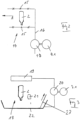
- the device serves to treat containers 2, which are shown in the figures as bottles, but can also be containers with a different design and/or function, for example cans or other bottle- or can-like containers, transport boxes for bottles or similar containers or for other transport goods, for example transport boxes made of plastic.
- the device 1 is part of an overall system which is connected to one another in a transport or conveying direction A in which the containers 2 are moved through the system. for example directly and/or via appropriate conveyors or transport devices provided between the individual devices.
- the containers 2 are fed to the device 1 or to a container inlet 1.1 of this device via an external conveyor 3. After treatment, the containers 2 are discharged to a container outlet 1.2 of the device 1 via an external conveyor 4 and, for example, forwarded to another device in the overall system.
- the containers 2 are transported on an internal conveyor, which is located in the Figure 1 is only indicated very schematically with the broken line 5, between the container inlet 1.1 and the container outlet 1.2.
- the containers 2 are then treated on this device-internal conveyor 5, whereby this treatment, as the following explanations show, can be of very different types, depending on the respective special function of the device 1.
- the device 1 is designed, among other things, with an electric drive group 6 with at least one electric drive motor 6.1, specifically for the motor drive of at least one higher-level functional element of the device 1, for example for driving the transport element 5 inside the device.
- the device 1 is designed, among other things, with a further electric drive group 7 with at least one electric drive motor 7.1, which serves to drive further functional elements, namely pumps of the device 1.
- the drive motors 6.1 and 7.1 are at least partially frequency-controlled electric motors that are operated via frequency converters 8 and 9, respectively, in such a way that their speed and/or power can be controlled or regulated very precisely by a control device 10 controlling the frequency converters 8 and 9, independently of the frequency of the general supply network, and largely independently of the respective load on the drive groups 6 and 7 or the drive motors 6.1 and 7.1, whereby the torques of the drive motors 6.1 and 7.1 can be kept very precisely within desired limit values, preferably over a wide speed range.
- the control of the frequency converters 8 and 9 by the, for example, computer-aided control electronics 10 takes place, for example, taking into account control programs and/or data and/or characteristics stored in a memory 11 of the control electronics 10, in particular taking into account characteristics of the functional elements driven by the electric drive 7, namely pumps, and/or depending on sensor signals supplied by sensors 12 provided in and/or on the device 1, for example by temperature sensors, flow meters, pressure sensors, etc., and/or depending on control signals or data which are fed to the control device 10 via at least one data connection or line 13, for example designed as a data and/or control bus, and which, for example, reflect or correspond to the operating state of the entire system and/or at least one device which precedes the device 1 in the overall system in the transport direction A or which follows the device 1.
- the device 1 or its drive groups 6 and 7 are controlled by the control device 10 in such a way that, when the entire system is operating without problems, the device 1 is also operated with the required target output (containers 2 treated per unit of time
- the control device 10 controls the drive groups 6 and 7 or their drive motors 6.1 and 7.1 via the frequency converters 8 and 9 in such a way that at least the drive group 7 or the drive motors 7.1 therein are not completely switched off, but continue to operate in a standby mode, in such a way that in this standby mode the speed or frequency of the network driving the drive motors is reduced to a frequency range between 40 Hertz and 5 Hertz.
- the power and/or the speed of the drive group 7 or its drive motors 7.1 can also be reduced to a range between 90% and 5% of the rated power or the rated speed of the drives 6 and 7 and thus be sufficient to avoid undesirable long time delays and/or excessive starting currents when restarting the device or when returning to the target speed and/or power after the fault has been rectified.
- the functional elements or auxiliary units driven by the drive group 7 or by the frequency-controlled drive motors 7.1 therein in a cleaning machine for cleaning containers 2 in the form of bottles are pumps in various treatment zones, for example circulation pumps for circulating cleaning and treatment liquids, in particular also for heating treatment zones, pumps used in conjunction with heat exchangers, pumps for flushing or overflowing the containers 2 in treatment zones for removing labels and/or for removing other foreign or solid substances from or from the containers, pumps in treatment zones for internal and external spraying of the containers with a cleaning liquid (lye) containing cleaning agents or cleaning additives, pumps in treatment zones for the final internal or external spraying of the containers with fresh water, drives for label and shard removal, etc.
- circulation pumps for circulating cleaning and treatment liquids in particular also for heating treatment zones
- pumps used in conjunction with heat exchangers pumps for flushing or overflowing the containers 2 in treatment zones for removing labels and/or for removing other foreign or solid substances from or from the containers
- the device 1 is a cleaning machine for cleaning the containers 2 designed as bottles.
- a cleaning machine for cleaning the containers 2 designed as bottles.
- a cleaning machine also has, in the manner known to the person skilled in the art, treatment zones which, as shown in the Figure 2 shown schematically, serve as spray zones 14 for the internal and external spraying of the containers 2 held in receptacles of the device-internal conveyor 5 with cleaning liquids, for example with lye or fresh water.
- spray nozzles 15 are provided on the transport path on which the containers 2 are moved through the respective spray zone 14, which are then connected via at least one line 16 with at least one pump 17 to a source (not shown) for the respective treatment liquid.
- each spray zone 14 or a group of several spray zones 14 is assigned a pump 17 which is driven by a frequency-controlled drive or pump motor 7.1.
- the power or speed of, among others, the drive group 6 driving the device-internal conveyor 5 is reduced via the control device 10 in order to adapt to the current performance of the overall system, but not the speed and/or power of the drive group 7 driving the pumps 17.
- the drive group 6 for the device-internal conveyor 5 is switched off and the speed and/or power of the drive group 7 or at least some of the drive motors 7.1 there are reduced, and the speed and/or power of the associated pumps 17 are reduced in such a way that the lines 16 remain reliably filled with the respective cleaning liquid, i.e. these lines are prevented from running dry.
- the speed and/or power of the associated pump 17 is reduced, for example, so that the treatment liquid (fresh water) can just be seen coming out of the spray nozzles 15.
- the volume flow generated by the respective pump 17 is significantly below the volume flow during target or normal operation, for example below 90% but above 5% of the volume flow during normal operation.
- the volume flow is particularly preferably reduced to a range below 70% but above 20% of the volume flow during target or normal operation.
- the speed and/or power of the associated pump 17 is reduced in such a way that the containers are kept in a completely wetted state, i.e. the treatment liquid on and in the containers 2 is prevented from drying out or drying out, and thus dried residues of the lye or treatment liquid that are difficult to remove later are reliably avoided.
- the volume flow generated by the respective pump 17 is significantly below the volume flow during target or normal operation, for example below 90%, but above 5% of the volume flow during normal operation.
- the volume flow of the lye spray is particularly preferably reduced to a range below 70%, but above 20% of the volume flow during target or normal operation.
- the pumps 17 are controlled for spraying the containers 2 with the cleaning liquid (lye) containing cleaning additives and for the final spraying of the containers 2 with fresh water.
- At least one station is often provided on the conveyor line formed by the device-internal conveyor 5, where labels are preferably removed, for example by exposing the bottles to a large volume flow of the cleaning or treatment liquid.
- a station is described in the Figure 3 shown schematically with regard to their function, namely with an overflow device 19 for applying the cleaning or treatment liquid to the containers 2 and with a pump 20 driven by a pump or drive motor 7.1.
- the treatment liquid is caught or collected in a tub 22 together with the labels 21 detached from the containers 2 and flows back to the pump 20 via a label discharge 23, for example in the form of a rotating driven sieve belt.
- the drive motor 7.1 and thus the pump 20 will operate at reduced Power, ie for example with a power below 90% but above 5% of the target or normal power, so that a certain liquid flow moving the labels 21 to the label outlet 23 is maintained and thereby a possibly difficult to dissolve deposit of detached labels 21 in the treatment station 18, for example on the bottom of the tank 22, is avoided.
- reduced Power ie for example with a power below 90% but above 5% of the target or normal power
- the drive motor 7.1 and the associated pump 20 of the label slurry are operated such that the performance is below 70% but above 20% of the performance at the target or normal performance.
- the power of the drive motors is reduced in the event of a major disruption to such an extent that the labels to be removed settle on the floor of the cleaning machine, resulting in further energy savings.
- the drive motor and the associated pump 20 of the label swirl system are temporarily operated at an increased power in order to achieve a stronger volume flow for a certain time interval, which is able to stir up the labels lying on the floor and thus also remove them from the cleaning machine.
- the label discharge 23 is also operated at a reduced power, for example at a power below 90% but above 5% of the target or normal power, in such a way that the moving masses of the label discharge 23 do not come to a complete standstill and thus undesirably high starting currents of the drive motor 7.1 for the label discharge 23 are avoided.
Landscapes
- Engineering & Computer Science (AREA)
- Mechanical Engineering (AREA)
- Cleaning In General (AREA)
- Filling Of Jars Or Cans And Processes For Cleaning And Sealing Jars (AREA)
- Cleaning By Liquid Or Steam (AREA)
- Supplying Of Containers To The Packaging Station (AREA)
Claims (10)
- Procédé pour faire fonctionner un dispositif (1) pour le traitement de contenants (2), avec au moins un groupe d'entraînement (6, 7) présentant au moins un moteur d'entraînement (6.1, 7.1) électrique pour l'entraînement d'ensembles secondaires ou d'autres éléments fonctionnels du dispositif, dans lequel la vitesse de rotation ou la puissance de l'au moins un groupe d'entraînement ou de l'au moins un moteur d'entraînement (7.1) situé à cet endroit est adaptée à l'état de fonctionnement concerné du dispositif (1) ou d'une installation présentant ledit dispositif, et dans lequel l'au moins un moteur d'entraînement (7.1) de l'au moins un groupe d'entraînement (7) est un moteur d'entraînement (7.1) électrique commandé en fréquence fonctionnant par l'intermédiaire d'un convertisseur de fréquence (8, 9) et l'adaptation de la vitesse de rotation ou de la puissance est effectuée par la modification de la fréquence de la tension de sortie du convertisseur de fréquence associé au moteur d'entraînement (7.1) concerné, dans lequel le dispositif est réalisé en tant que machine de nettoyage et l'élément fonctionnel entraîné par l'au moins un groupe d'entraînement (7) ou le moteur d'entraînement (7.1) situé à cet endroit est au moins une pompe (17, 20) pour un liquide de traitement ou de nettoyage, caractérisé en ce que dans le cas d'un dysfonctionnement dans le dispositif (1) ou dans l'installation, l'au moins un groupe d'entraînement (7) ou l'au moins un entraînement (7.1) situé à cet endroit fonctionne dans un mode d'attente avec une vitesse de rotation ou une puissance réduite, qui est choisie de telle sorte qu'un redémarrage du dispositif est possible une fois le dysfonctionnement éliminé sans ou sensiblement sans décalage de temps ou sans un courant de démarrage surélevé.
- Procédé selon la revendication 1, caractérisé en ce que dans le cas d'un dispositif avec au moins un transporteur (5) interne au dispositif, avec lequel les contenants (2) sont déplacés à travers le dispositif (1) et qui est entraîné par l'intermédiaire d'au moins un moteur d'entraînement (6.1) de l'au moins un groupe d'entraînement (6), dans le cas d'un dysfonctionnement dans le dispositif (1) ou dans l'installation, l'au moins un moteur d'entraînement (6.1) pour le transporteur (5) interne au dispositif est arrêté et l'au moins un groupe d'entraînement (7) ou un moteur d'entraînement (7.1) pour d'autres éléments fonctionnels situé à cet endroit fonctionne avec une puissance ou vitesse de rotation réduite.
- Procédé selon la revendication 1 ou 2, caractérisé en ce que dans le cas d'un dysfonctionnement dans le dispositif (1) ou dans l'installation, la vitesse de rotation ou la puissance de l'au moins un groupe d'entraînement ou d'un moteur d'entraînement 7.1) situé à cet endroit est réduite sur une valeur inférieure à 90 %, toutefois supérieure à 5 % de la puissance théorique ou normale.
- Procédé selon l'une quelconque des revendications précédentes, caractérisé en ce que lors de la réalisation du dispositif (1) en tant que machine de nettoyage, dans le cas d'un dysfonctionnement dans le dispositif ou dans l'installation, la vitesse de rotation ou la puissance de l'au moins un groupe d'entraînement (7) ou d'au moins un moteur d'entraînement (7.1) situé à cet endroit, faisant office de moteur de pompe, sont réduites de telle manière qu'aucun flux volumique ou sensiblement aucun flux volumique dudit liquide n'est obtenu dans un conduit (16) raccordé à la pompe (17) pour un liquide de nettoyage ou de traitement, une marche à vide du conduit (16) est toutefois empêchée.
- Procédé selon la revendication 4, caractérisé en ce que la pompe (17) fonctionne avec une vitesse de rotation ou une puissance réduite de telle manière qu'un liquide de nettoyage ou de traitement refoulé avec la pompe sort encore précisément au niveau d'au moins une buse de pulvérisation (15) raccordée, de préférence au niveau de toutes les buses de pulvérisation (15) raccordées.
- Procédé selon la revendication 5, caractérisé en ce que dans le cas d'un dysfonctionnement, la vitesse de rotation ou la puissance de l'au moins un moteur d'entraînement (7.1) est réduite à moins de 90 %, mais plus de 5 % de la puissance théorique ou normale.
- Procédé selon la revendication 4, caractérisé en ce que la pompe (17) fonctionne avec une vitesse de rotation ou une puissance réduite de telle manière qu'un liquide de nettoyage ou de traitement refoulé avec la pompe est distribué au niveau d'au moins une buse de pulvérisation (15) raccordée, de préférence au niveau de toutes les buses de pulvérisation (15) raccordées en une quantité telle qui empêche encore précisément un séchage du liquide de nettoyage ou de traitement au niveau des ou dans des contenants (2).
- Procédé selon la revendication 7, caractérisé en ce que dans le cas d'un dysfonctionnement, la vi- tesse de rotation ou la puissance de l'au moins un moteur d'entraînement (7.1) est réduite à moins de 90 %, mais plus de 5 % de la puissance théorique ou normale.
- Procédé selon l'une quelconque des revendications précédentes, caractérisé en ce que l'élément fonctionnel entraîné par l'au moins un moteur d'entraînement (7.1) de l'au moins un groupe d'entraînement 7) est une pompe (20) d'un poste de débordement (18) pour retirer des étiquettes (21) ou des corps extérieurs au niveau des ou hors des contenants (2), et que le moteur d'entraînement (7.1) de la pompe (20) fonctionne dans le cas d'un dysfonctionnement dans le dispositif (1) ou dans l'installation avec une vitesse de rotation ou une puissance réduite de telle manière qu'un dépôt d'étiquettes (21) au niveau de faces du poste de débordement (18) est précisément encore empêché.
- Procédé selon la revendication 7, caractérisé en ce que dans le cas d'un dysfonctionnement, la vitesse de rotation ou la puissance de l'au moins un moteur d'entraînement (7.1) est réduite à moins de 90 %, mais plus de 5 % de la puissance théorique ou normale.
Priority Applications (1)
| Application Number | Priority Date | Filing Date | Title |
|---|---|---|---|
| SI200932085T SI2334446T2 (sl) | 2008-10-02 | 2009-09-29 | Naprava in postopek za obdelavo vsebnikov |
Applications Claiming Priority (2)
| Application Number | Priority Date | Filing Date | Title |
|---|---|---|---|
| DE102008049937A DE102008049937A1 (de) | 2008-10-02 | 2008-10-02 | Vorrichtung sowie Verfahren zum Behandeln von Behältern |
| PCT/EP2009/006989 WO2010037517A2 (fr) | 2008-10-02 | 2009-09-29 | Dispositif et procédé pour traiter des contenants |
Publications (3)
| Publication Number | Publication Date |
|---|---|
| EP2334446A2 EP2334446A2 (fr) | 2011-06-22 |
| EP2334446B1 EP2334446B1 (fr) | 2020-07-29 |
| EP2334446B2 true EP2334446B2 (fr) | 2024-09-04 |
Family
ID=41718768
Family Applications (1)
| Application Number | Title | Priority Date | Filing Date |
|---|---|---|---|
| EP09778759.2A Active EP2334446B2 (fr) | 2008-10-02 | 2009-09-29 | Dispositif et procédé pour traiter des contenants |
Country Status (6)
| Country | Link |
|---|---|
| EP (1) | EP2334446B2 (fr) |
| CN (1) | CN102131595B (fr) |
| DE (1) | DE102008049937A1 (fr) |
| RU (1) | RU2469804C1 (fr) |
| SI (1) | SI2334446T2 (fr) |
| WO (1) | WO2010037517A2 (fr) |
Families Citing this family (10)
| Publication number | Priority date | Publication date | Assignee | Title |
|---|---|---|---|---|
| DE102011119584A1 (de) * | 2011-10-05 | 2013-04-11 | Focke & Co. (Gmbh & Co. Kg) | System zum Betreiben einer Verpackungsanlage |
| DE102012102965A1 (de) | 2012-04-04 | 2013-10-10 | Krones Ag | Verfahren zur Steuerung eines Füllers |
| DE102012112369A1 (de) | 2012-12-17 | 2014-06-18 | Krones Ag | Verfahren zur Ermittlung einer Ressourceneffizienz einer Anlage zum Herstellen von Getränkebehältnissen |
| CN103569922A (zh) * | 2013-10-31 | 2014-02-12 | 苏州泰科尼光伏材料有限公司 | 一种用于eva胶粒搅拌的添加剂溶液自动灌装装置 |
| DE102014100945A1 (de) | 2014-01-28 | 2015-07-30 | Khs Gmbh | Vorrichtung sowie Verfahren zur Fehlererkennung in Maschinen |
| DE102018111235A1 (de) | 2018-05-09 | 2019-11-14 | Krones Ag | Vorrichtung zum Umformen von Kunststoffvorformlingen zu Kunststoffbehältnissen mit entkoppelten Antrieben |
| DE102020126355A1 (de) | 2020-10-08 | 2022-04-14 | Krones Aktiengesellschaft | Verfahren zum Betreiben einer Maschine in einer Verarbeitungsanlage für Behälter und Maschine zur Behandlung von Behältern |
| DE102021110009A1 (de) | 2021-04-20 | 2022-10-20 | Krones Aktiengesellschaft | Behälterbehandlungsanlage und Behälterbehandlungsverfahren zur Behandlung von Behältern |
| DE102021114049A1 (de) | 2021-05-31 | 2022-12-01 | Rovema Gmbh | Verfahren zum Betrieb einer Schlauchbeutelmaschine |
| DE102024106556A1 (de) * | 2024-03-07 | 2025-09-11 | Krones Aktiengesellschaft | Verfahren zum Regeln einer Behälterbehandlungsanlage und Behälterbehandlungsanlage zum Ausführen des Verfahrens |
Citations (2)
| Publication number | Priority date | Publication date | Assignee | Title |
|---|---|---|---|---|
| DE4431052A1 (de) † | 1994-09-01 | 1996-03-07 | Elektro Maschinen Und Apparate | Einrichtung zum Entfernen von Kronenkorken |
| WO2008055663A1 (fr) † | 2006-11-10 | 2008-05-15 | Khs Ag | Poste de projection pour machine de nettoyage de bouteilles ou de récipients similaires et machine de nettoyage dotée d'au moins un poste de projection |
Family Cites Families (23)
| Publication number | Priority date | Publication date | Assignee | Title |
|---|---|---|---|---|
| DE1803332A1 (de) | 1968-10-16 | 1970-05-27 | Hermann Kronseder | Etikettiermaschine mit Leistungsverstelleinrichtung |
| DE2122152A1 (de) | 1971-05-05 | 1972-11-16 | Kronseder, Hermann, 8402 Neutraubling | Flaschenbehandlungsanlage |
| DE2254972A1 (de) * | 1972-11-10 | 1974-05-22 | Winterwerb Streng Co Gmbh | Flaschenreinigungsmaschine |
| DE3120603A1 (de) * | 1981-05-23 | 1982-12-23 | Holstein Und Kappert Gmbh, 4600 Dortmund | Verfahren zur ermittlung der abgabeleistung und behandlungsanzahl von gefaessspeichernden behandlungsmaschinen |
| GB2182461B (en) | 1985-11-05 | 1989-10-04 | Nestle Sa | Steam injection process |
| DD285649A5 (de) * | 1989-10-12 | 1990-12-19 | ������@������������k�� | Verfahren zum steuern der arbeitsgeschwindigkeit von verarbeitungsmaschinen |
| DE4037899A1 (de) * | 1990-11-28 | 1992-06-04 | Brechtelterra Spezialtiefbau U | Vorrichtung zum reinigen eines brunnenrohres und der filterschuettung in wasserbrunnen |
| DE4304814A1 (de) | 1993-02-17 | 1994-08-18 | Kronseder Maschf Krones | Verfahren zur Beeinflussung der Transportgeschwindigkeit |
| DE69415423T2 (de) * | 1993-07-12 | 1999-06-10 | Pepsico Inc., Purchase, N.Y. | Hochgeschwindigkeits-Flaschenspülmaschine und Spritzdüsenzusammensetzung |
| DE4434176C2 (de) * | 1994-09-24 | 2001-08-16 | Khs Masch & Anlagenbau Ag | Verfahren zur leistungsbezogenen Versorgung von Maschinen in Gefäßbehandlungsanlagen |
| AU697630B2 (en) | 1995-02-22 | 1998-10-15 | Afuema Abfullmaschinen Gmbh | Procedure for adjusting a filling jet |
| JP3367588B2 (ja) * | 1995-08-18 | 2003-01-14 | 株式会社イシダ | 製袋包装機における縦シール機構 |
| DE19741476C5 (de) | 1997-09-15 | 2010-06-02 | Krones Ag | Maschine zum Behandeln von Gefäßen |
| JP3856597B2 (ja) * | 1998-12-16 | 2006-12-13 | 株式会社東京自働機械製作所 | 縦形製袋充填包装機の縦シール制御装置 |
| JP4329198B2 (ja) | 2000-01-25 | 2009-09-09 | シブヤマシナリー株式会社 | 容器洗浄装置 |
| CN100457600C (zh) | 2002-12-12 | 2009-02-04 | 三得利株式会社 | 液体灌装方法和装置 |
| DE20300142U1 (de) | 2003-01-08 | 2003-10-23 | KHS Maschinen- und Anlagenbau AG, 44143 Dortmund | Vorrichtung zum Transportieren von Gefäßen |
| DE10300642C5 (de) | 2003-01-09 | 2018-02-22 | Krones Aktiengesellschaft | Fördervorrichtung |
| DE20313908U1 (de) * | 2003-09-04 | 2004-02-19 | Strauß, Jörn | Anordnung zum Reinigen von Schalen |
| RU59452U1 (ru) * | 2005-04-18 | 2006-12-27 | Александр Николаевич Панфилов | Машина очистная малогабаритная |
| DE102005026080B4 (de) | 2005-06-07 | 2007-06-06 | Khs Ag | Flaschenreinigungsmaschine |
| US7803232B2 (en) | 2005-11-17 | 2010-09-28 | Mcbrady Engineering, Inc. | Multi-pass inverting bottle cleaner |
| CN200964291Y (zh) * | 2006-10-31 | 2007-10-24 | 长沙楚天科技有限公司 | 链传动机构的升降装置 |
-
2008
- 2008-10-02 DE DE102008049937A patent/DE102008049937A1/de not_active Withdrawn
-
2009
- 2009-09-29 EP EP09778759.2A patent/EP2334446B2/fr active Active
- 2009-09-29 CN CN2009801328256A patent/CN102131595B/zh active Active
- 2009-09-29 WO PCT/EP2009/006989 patent/WO2010037517A2/fr not_active Ceased
- 2009-09-29 RU RU2011117306/05A patent/RU2469804C1/ru not_active IP Right Cessation
- 2009-09-29 SI SI200932085T patent/SI2334446T2/sl unknown
Patent Citations (2)
| Publication number | Priority date | Publication date | Assignee | Title |
|---|---|---|---|---|
| DE4431052A1 (de) † | 1994-09-01 | 1996-03-07 | Elektro Maschinen Und Apparate | Einrichtung zum Entfernen von Kronenkorken |
| WO2008055663A1 (fr) † | 2006-11-10 | 2008-05-15 | Khs Ag | Poste de projection pour machine de nettoyage de bouteilles ou de récipients similaires et machine de nettoyage dotée d'au moins un poste de projection |
Also Published As
| Publication number | Publication date |
|---|---|
| SI2334446T2 (sl) | 2024-10-30 |
| EP2334446A2 (fr) | 2011-06-22 |
| SI2334446T1 (sl) | 2020-09-30 |
| DE102008049937A1 (de) | 2010-04-29 |
| WO2010037517A2 (fr) | 2010-04-08 |
| RU2469804C1 (ru) | 2012-12-20 |
| CN102131595A (zh) | 2011-07-20 |
| WO2010037517A3 (fr) | 2010-06-17 |
| EP2334446B1 (fr) | 2020-07-29 |
| CN102131595B (zh) | 2013-04-03 |
Similar Documents
| Publication | Publication Date | Title |
|---|---|---|
| EP2334446B2 (fr) | Dispositif et procédé pour traiter des contenants | |
| DE19741242C1 (de) | Anlage zum Reinigen einer Abfüllanlage | |
| DE102014103671B3 (de) | Behälterbehandlungsmaschine sowie Verfahren zum Zu- und/oder Abführen von Behältern zu einer Behälterbehandlungsmaschine | |
| EP2218523B1 (fr) | Machine de nettoyage de bouteilles | |
| EP2547590B1 (fr) | Tunnel de rétraction pour l'application de films rétractables, procédé pour faire fonctionner ou commander un tunnel de rétraction et dispositif de production comportant un tunnel de rétraction | |
| EP3860939B1 (fr) | Installation de remplissage et procédé pour le remplissage de bouteilles adapté à la demande | |
| DE102004026565B4 (de) | Verfahren zum Reinigen von Flaschen o.dgl. Behälter sowie Reinigungsmaschine | |
| EP2001774A1 (fr) | Système de transport de bouteilles ou de récipients similaires et installation de traitement de bouteilles ou de récipients similaires | |
| EP2046670A1 (fr) | Dispositif de transport | |
| EP2999635A1 (fr) | Machine de traitement de récipient ainsi que procédé servant à faire fonctionner une machine de traitement de récipient | |
| EP3310664B1 (fr) | Système et procédé de remplissage de récipients | |
| EP3083087B1 (fr) | Dispositif et procédé pour le nettoyage de conteneurs | |
| EP2097184A1 (fr) | Poste de projection pour machine de nettoyage de bouteilles ou de récipients similaires et machine de nettoyage dotée d'au moins un poste de projection | |
| EP2323909A1 (fr) | Procédé et appareillage pour manipuler des récipients à boissons | |
| DE3815441C2 (fr) | ||
| DE202008013072U1 (de) | Vorrichtung zum Behandeln von Behältern | |
| EP4142958A1 (fr) | Commande d'une machine de nettoyage de récipient en fonction du débit de récipient d'un système/machine de traitement de récipient en aval | |
| WO2008095576A2 (fr) | Procédé de réduction de la consommation d'énergie dans des usines de pasteurisation, et installation de remplissage | |
| WO2024052534A1 (fr) | Installation de mise en bouteille, mélangeur pour une installation de mise en bouteille et procédé de préparation d'un produit chimique | |
| EP2777830B1 (fr) | Procédé et appareil pour nettoyer un segment de transport | |
| EP3615462B1 (fr) | Dispositif de manutention, ainsi que machine pour la manutention de récipients | |
| WO2013023739A1 (fr) | Procédé servant à commander un dispositif de pasteurisation et dispositif de pasteurisation | |
| EP4494839A1 (fr) | Installation de traitement de récipients pour la fabrication et le traitement de préformes | |
| DE20300142U1 (de) | Vorrichtung zum Transportieren von Gefäßen | |
| EP3294661A1 (fr) | Machine de traitement de récipients et/ou de denrées alimentaires munie d'une amenée de fluide de travail |
Legal Events
| Date | Code | Title | Description |
|---|---|---|---|
| PUAI | Public reference made under article 153(3) epc to a published international application that has entered the european phase |
Free format text: ORIGINAL CODE: 0009012 |
|
| 17P | Request for examination filed |
Effective date: 20110502 |
|
| AK | Designated contracting states |
Kind code of ref document: A2 Designated state(s): AT BE BG CH CY CZ DE DK EE ES FI FR GB GR HR HU IE IS IT LI LT LU LV MC MK MT NL NO PL PT RO SE SI SK SM TR |
|
| AX | Request for extension of the european patent |
Extension state: AL BA RS |
|
| DAX | Request for extension of the european patent (deleted) | ||
| 17Q | First examination report despatched |
Effective date: 20141118 |
|
| STAA | Information on the status of an ep patent application or granted ep patent |
Free format text: STATUS: EXAMINATION IS IN PROGRESS |
|
| RAP1 | Party data changed (applicant data changed or rights of an application transferred) |
Owner name: KHS GMBH |
|
| GRAP | Despatch of communication of intention to grant a patent |
Free format text: ORIGINAL CODE: EPIDOSNIGR1 |
|
| STAA | Information on the status of an ep patent application or granted ep patent |
Free format text: STATUS: GRANT OF PATENT IS INTENDED |
|
| GRAS | Grant fee paid |
Free format text: ORIGINAL CODE: EPIDOSNIGR3 |
|
| INTG | Intention to grant announced |
Effective date: 20200528 |
|
| GRAA | (expected) grant |
Free format text: ORIGINAL CODE: 0009210 |
|
| STAA | Information on the status of an ep patent application or granted ep patent |
Free format text: STATUS: THE PATENT HAS BEEN GRANTED |
|
| AK | Designated contracting states |
Kind code of ref document: B1 Designated state(s): AT BE BG CH CY CZ DE DK EE ES FI FR GB GR HR HU IE IS IT LI LT LU LV MC MK MT NL NO PL PT RO SE SI SK SM TR |
|
| REG | Reference to a national code |
Ref country code: GB Ref legal event code: FG4D Free format text: NOT ENGLISH |
|
| REG | Reference to a national code |
Ref country code: CH Ref legal event code: NV Representative=s name: E. BLUM AND CO. AG PATENT- UND MARKENANWAELTE , CH Ref country code: CH Ref legal event code: EP |
|
| REG | Reference to a national code |
Ref country code: AT Ref legal event code: REF Ref document number: 1295186 Country of ref document: AT Kind code of ref document: T Effective date: 20200815 |
|
| REG | Reference to a national code |
Ref country code: IE Ref legal event code: FG4D Free format text: LANGUAGE OF EP DOCUMENT: GERMAN |
|
| REG | Reference to a national code |
Ref country code: DE Ref legal event code: R096 Ref document number: 502009016250 Country of ref document: DE |
|
| REG | Reference to a national code |
Ref country code: LT Ref legal event code: MG4D |
|
| REG | Reference to a national code |
Ref country code: NL Ref legal event code: MP Effective date: 20200729 |
|
| PG25 | Lapsed in a contracting state [announced via postgrant information from national office to epo] |
Ref country code: HR Free format text: LAPSE BECAUSE OF FAILURE TO SUBMIT A TRANSLATION OF THE DESCRIPTION OR TO PAY THE FEE WITHIN THE PRESCRIBED TIME-LIMIT Effective date: 20200729 Ref country code: SE Free format text: LAPSE BECAUSE OF FAILURE TO SUBMIT A TRANSLATION OF THE DESCRIPTION OR TO PAY THE FEE WITHIN THE PRESCRIBED TIME-LIMIT Effective date: 20200729 Ref country code: PT Free format text: LAPSE BECAUSE OF FAILURE TO SUBMIT A TRANSLATION OF THE DESCRIPTION OR TO PAY THE FEE WITHIN THE PRESCRIBED TIME-LIMIT Effective date: 20201130 Ref country code: ES Free format text: LAPSE BECAUSE OF FAILURE TO SUBMIT A TRANSLATION OF THE DESCRIPTION OR TO PAY THE FEE WITHIN THE PRESCRIBED TIME-LIMIT Effective date: 20200729 Ref country code: NO Free format text: LAPSE BECAUSE OF FAILURE TO SUBMIT A TRANSLATION OF THE DESCRIPTION OR TO PAY THE FEE WITHIN THE PRESCRIBED TIME-LIMIT Effective date: 20201029 Ref country code: BG Free format text: LAPSE BECAUSE OF FAILURE TO SUBMIT A TRANSLATION OF THE DESCRIPTION OR TO PAY THE FEE WITHIN THE PRESCRIBED TIME-LIMIT Effective date: 20201029 Ref country code: LT Free format text: LAPSE BECAUSE OF FAILURE TO SUBMIT A TRANSLATION OF THE DESCRIPTION OR TO PAY THE FEE WITHIN THE PRESCRIBED TIME-LIMIT Effective date: 20200729 Ref country code: FI Free format text: LAPSE BECAUSE OF FAILURE TO SUBMIT A TRANSLATION OF THE DESCRIPTION OR TO PAY THE FEE WITHIN THE PRESCRIBED TIME-LIMIT Effective date: 20200729 Ref country code: GR Free format text: LAPSE BECAUSE OF FAILURE TO SUBMIT A TRANSLATION OF THE DESCRIPTION OR TO PAY THE FEE WITHIN THE PRESCRIBED TIME-LIMIT Effective date: 20201030 |
|
| PG25 | Lapsed in a contracting state [announced via postgrant information from national office to epo] |
Ref country code: IS Free format text: LAPSE BECAUSE OF FAILURE TO SUBMIT A TRANSLATION OF THE DESCRIPTION OR TO PAY THE FEE WITHIN THE PRESCRIBED TIME-LIMIT Effective date: 20201129 Ref country code: LV Free format text: LAPSE BECAUSE OF FAILURE TO SUBMIT A TRANSLATION OF THE DESCRIPTION OR TO PAY THE FEE WITHIN THE PRESCRIBED TIME-LIMIT Effective date: 20200729 Ref country code: PL Free format text: LAPSE BECAUSE OF FAILURE TO SUBMIT A TRANSLATION OF THE DESCRIPTION OR TO PAY THE FEE WITHIN THE PRESCRIBED TIME-LIMIT Effective date: 20200729 |
|
| PG25 | Lapsed in a contracting state [announced via postgrant information from national office to epo] |
Ref country code: NL Free format text: LAPSE BECAUSE OF FAILURE TO SUBMIT A TRANSLATION OF THE DESCRIPTION OR TO PAY THE FEE WITHIN THE PRESCRIBED TIME-LIMIT Effective date: 20200729 |
|
| REG | Reference to a national code |
Ref country code: DE Ref legal event code: R026 Ref document number: 502009016250 Country of ref document: DE |
|
| PG25 | Lapsed in a contracting state [announced via postgrant information from national office to epo] |
Ref country code: EE Free format text: LAPSE BECAUSE OF FAILURE TO SUBMIT A TRANSLATION OF THE DESCRIPTION OR TO PAY THE FEE WITHIN THE PRESCRIBED TIME-LIMIT Effective date: 20200729 Ref country code: DK Free format text: LAPSE BECAUSE OF FAILURE TO SUBMIT A TRANSLATION OF THE DESCRIPTION OR TO PAY THE FEE WITHIN THE PRESCRIBED TIME-LIMIT Effective date: 20200729 Ref country code: SM Free format text: LAPSE BECAUSE OF FAILURE TO SUBMIT A TRANSLATION OF THE DESCRIPTION OR TO PAY THE FEE WITHIN THE PRESCRIBED TIME-LIMIT Effective date: 20200729 Ref country code: RO Free format text: LAPSE BECAUSE OF FAILURE TO SUBMIT A TRANSLATION OF THE DESCRIPTION OR TO PAY THE FEE WITHIN THE PRESCRIBED TIME-LIMIT Effective date: 20200729 Ref country code: MC Free format text: LAPSE BECAUSE OF FAILURE TO SUBMIT A TRANSLATION OF THE DESCRIPTION OR TO PAY THE FEE WITHIN THE PRESCRIBED TIME-LIMIT Effective date: 20200729 |
|
| PLBI | Opposition filed |
Free format text: ORIGINAL CODE: 0009260 |
|
| PLAX | Notice of opposition and request to file observation + time limit sent |
Free format text: ORIGINAL CODE: EPIDOSNOBS2 |
|
| 26 | Opposition filed |
Opponent name: KRONES AG Effective date: 20210429 |
|
| REG | Reference to a national code |
Ref country code: BE Ref legal event code: MM Effective date: 20200930 |
|
| GBPC | Gb: european patent ceased through non-payment of renewal fee |
Effective date: 20201029 |
|
| PG25 | Lapsed in a contracting state [announced via postgrant information from national office to epo] |
Ref country code: LU Free format text: LAPSE BECAUSE OF NON-PAYMENT OF DUE FEES Effective date: 20200929 Ref country code: SK Free format text: LAPSE BECAUSE OF FAILURE TO SUBMIT A TRANSLATION OF THE DESCRIPTION OR TO PAY THE FEE WITHIN THE PRESCRIBED TIME-LIMIT Effective date: 20200729 |
|
| PG25 | Lapsed in a contracting state [announced via postgrant information from national office to epo] |
Ref country code: IE Free format text: LAPSE BECAUSE OF NON-PAYMENT OF DUE FEES Effective date: 20200929 Ref country code: GB Free format text: LAPSE BECAUSE OF NON-PAYMENT OF DUE FEES Effective date: 20201029 Ref country code: BE Free format text: LAPSE BECAUSE OF NON-PAYMENT OF DUE FEES Effective date: 20200930 |
|
| PLBB | Reply of patent proprietor to notice(s) of opposition received |
Free format text: ORIGINAL CODE: EPIDOSNOBS3 |
|
| PG25 | Lapsed in a contracting state [announced via postgrant information from national office to epo] |
Ref country code: TR Free format text: LAPSE BECAUSE OF FAILURE TO SUBMIT A TRANSLATION OF THE DESCRIPTION OR TO PAY THE FEE WITHIN THE PRESCRIBED TIME-LIMIT Effective date: 20200729 Ref country code: MT Free format text: LAPSE BECAUSE OF FAILURE TO SUBMIT A TRANSLATION OF THE DESCRIPTION OR TO PAY THE FEE WITHIN THE PRESCRIBED TIME-LIMIT Effective date: 20200729 Ref country code: CY Free format text: LAPSE BECAUSE OF FAILURE TO SUBMIT A TRANSLATION OF THE DESCRIPTION OR TO PAY THE FEE WITHIN THE PRESCRIBED TIME-LIMIT Effective date: 20200729 |
|
| PG25 | Lapsed in a contracting state [announced via postgrant information from national office to epo] |
Ref country code: MK Free format text: LAPSE BECAUSE OF FAILURE TO SUBMIT A TRANSLATION OF THE DESCRIPTION OR TO PAY THE FEE WITHIN THE PRESCRIBED TIME-LIMIT Effective date: 20200729 |
|
| APAH | Appeal reference modified |
Free format text: ORIGINAL CODE: EPIDOSCREFNO |
|
| APAW | Appeal reference deleted |
Free format text: ORIGINAL CODE: EPIDOSDREFNO |
|
| APBM | Appeal reference recorded |
Free format text: ORIGINAL CODE: EPIDOSNREFNO |
|
| APBP | Date of receipt of notice of appeal recorded |
Free format text: ORIGINAL CODE: EPIDOSNNOA2O |
|
| APBQ | Date of receipt of statement of grounds of appeal recorded |
Free format text: ORIGINAL CODE: EPIDOSNNOA3O |
|
| APBQ | Date of receipt of statement of grounds of appeal recorded |
Free format text: ORIGINAL CODE: EPIDOSNNOA3O |
|
| APBU | Appeal procedure closed |
Free format text: ORIGINAL CODE: EPIDOSNNOA9O |
|
| PUAH | Patent maintained in amended form |
Free format text: ORIGINAL CODE: 0009272 |
|
| STAA | Information on the status of an ep patent application or granted ep patent |
Free format text: STATUS: PATENT MAINTAINED AS AMENDED |
|
| 27A | Patent maintained in amended form |
Effective date: 20240904 |
|
| AK | Designated contracting states |
Kind code of ref document: B2 Designated state(s): AT BE BG CH CY CZ DE DK EE ES FI FR GB GR HR HU IE IS IT LI LT LU LV MC MK MT NL NO PL PT RO SE SI SK SM TR |
|
| REG | Reference to a national code |
Ref country code: DE Ref legal event code: R102 Ref document number: 502009016250 Country of ref document: DE |
|
| PGFP | Annual fee paid to national office [announced via postgrant information from national office to epo] |
Ref country code: CH Payment date: 20241001 Year of fee payment: 16 |
|
| REG | Reference to a national code |
Ref country code: CH Ref legal event code: U11 Free format text: ST27 STATUS EVENT CODE: U-0-0-U10-U11 (AS PROVIDED BY THE NATIONAL OFFICE) Effective date: 20251001 |
|
| PGFP | Annual fee paid to national office [announced via postgrant information from national office to epo] |
Ref country code: DE Payment date: 20250919 Year of fee payment: 17 |
|
| PGFP | Annual fee paid to national office [announced via postgrant information from national office to epo] |
Ref country code: IT Payment date: 20250923 Year of fee payment: 17 |
|
| PGFP | Annual fee paid to national office [announced via postgrant information from national office to epo] |
Ref country code: FR Payment date: 20250922 Year of fee payment: 17 Ref country code: AT Payment date: 20250919 Year of fee payment: 17 |
|
| PGFP | Annual fee paid to national office [announced via postgrant information from national office to epo] |
Ref country code: CZ Payment date: 20250925 Year of fee payment: 17 |
|
| PGFP | Annual fee paid to national office [announced via postgrant information from national office to epo] |
Ref country code: SI Payment date: 20250918 Year of fee payment: 17 |