EP2332509A1 - Gas mist pressure bath system - Google Patents
Gas mist pressure bath system Download PDFInfo
- Publication number
- EP2332509A1 EP2332509A1 EP10738541A EP10738541A EP2332509A1 EP 2332509 A1 EP2332509 A1 EP 2332509A1 EP 10738541 A EP10738541 A EP 10738541A EP 10738541 A EP10738541 A EP 10738541A EP 2332509 A1 EP2332509 A1 EP 2332509A1
- Authority
- EP
- European Patent Office
- Prior art keywords
- gas mist
- gas
- living
- pressure bath
- liquid
- Prior art date
- Legal status (The legal status is an assumption and is not a legal conclusion. Google has not performed a legal analysis and makes no representation as to the accuracy of the status listed.)
- Withdrawn
Links
Images


Classifications
-
- A—HUMAN NECESSITIES
- A61—MEDICAL OR VETERINARY SCIENCE; HYGIENE
- A61K—PREPARATIONS FOR MEDICAL, DENTAL OR TOILETRY PURPOSES
- A61K33/00—Medicinal preparations containing inorganic active ingredients
-
- A—HUMAN NECESSITIES
- A61—MEDICAL OR VETERINARY SCIENCE; HYGIENE
- A61H—PHYSICAL THERAPY APPARATUS, e.g. DEVICES FOR LOCATING OR STIMULATING REFLEX POINTS IN THE BODY; ARTIFICIAL RESPIRATION; MASSAGE; BATHING DEVICES FOR SPECIAL THERAPEUTIC OR HYGIENIC PURPOSES OR SPECIFIC PARTS OF THE BODY
- A61H33/00—Bathing devices for special therapeutic or hygienic purposes
- A61H33/02—Bathing devices for use with gas-containing liquid, or liquid in which gas is led or generated, e.g. carbon dioxide baths
-
- A—HUMAN NECESSITIES
- A61—MEDICAL OR VETERINARY SCIENCE; HYGIENE
- A61H—PHYSICAL THERAPY APPARATUS, e.g. DEVICES FOR LOCATING OR STIMULATING REFLEX POINTS IN THE BODY; ARTIFICIAL RESPIRATION; MASSAGE; BATHING DEVICES FOR SPECIAL THERAPEUTIC OR HYGIENIC PURPOSES OR SPECIFIC PARTS OF THE BODY
- A61H33/00—Bathing devices for special therapeutic or hygienic purposes
- A61H33/06—Artificial hot-air or cold-air baths; Steam or gas baths or douches, e.g. sauna or Finnish baths
- A61H33/10—Devices on tubs for steam baths
-
- A—HUMAN NECESSITIES
- A61—MEDICAL OR VETERINARY SCIENCE; HYGIENE
- A61H—PHYSICAL THERAPY APPARATUS, e.g. DEVICES FOR LOCATING OR STIMULATING REFLEX POINTS IN THE BODY; ARTIFICIAL RESPIRATION; MASSAGE; BATHING DEVICES FOR SPECIAL THERAPEUTIC OR HYGIENIC PURPOSES OR SPECIFIC PARTS OF THE BODY
- A61H33/00—Bathing devices for special therapeutic or hygienic purposes
- A61H33/14—Devices for gas baths with ozone, hydrogen, or the like
-
- A—HUMAN NECESSITIES
- A61—MEDICAL OR VETERINARY SCIENCE; HYGIENE
- A61H—PHYSICAL THERAPY APPARATUS, e.g. DEVICES FOR LOCATING OR STIMULATING REFLEX POINTS IN THE BODY; ARTIFICIAL RESPIRATION; MASSAGE; BATHING DEVICES FOR SPECIAL THERAPEUTIC OR HYGIENIC PURPOSES OR SPECIFIC PARTS OF THE BODY
- A61H35/00—Baths for specific parts of the body
-
- A—HUMAN NECESSITIES
- A61—MEDICAL OR VETERINARY SCIENCE; HYGIENE
- A61H—PHYSICAL THERAPY APPARATUS, e.g. DEVICES FOR LOCATING OR STIMULATING REFLEX POINTS IN THE BODY; ARTIFICIAL RESPIRATION; MASSAGE; BATHING DEVICES FOR SPECIAL THERAPEUTIC OR HYGIENIC PURPOSES OR SPECIFIC PARTS OF THE BODY
- A61H33/00—Bathing devices for special therapeutic or hygienic purposes
- A61H33/06—Artificial hot-air or cold-air baths; Steam or gas baths or douches, e.g. sauna or Finnish baths
- A61H2033/068—Steam baths
-
- A—HUMAN NECESSITIES
- A61—MEDICAL OR VETERINARY SCIENCE; HYGIENE
- A61H—PHYSICAL THERAPY APPARATUS, e.g. DEVICES FOR LOCATING OR STIMULATING REFLEX POINTS IN THE BODY; ARTIFICIAL RESPIRATION; MASSAGE; BATHING DEVICES FOR SPECIAL THERAPEUTIC OR HYGIENIC PURPOSES OR SPECIFIC PARTS OF THE BODY
- A61H2201/00—Characteristics of apparatus not provided for in the preceding codes
- A61H2201/16—Physical interface with patient
- A61H2201/1602—Physical interface with patient kind of interface, e.g. head rest, knee support or lumbar support
- A61H2201/165—Wearable interfaces
Definitions
- the present invention relates to a gas mist pressure bath system, in which a mist (called as “gas mist” hereafter) is prepared by pulverizing and dissolving carbon dioxide or oxygen, or a mixed gas (called as “gas” hereafter) of carbon dioxide and oxygen, and liquid, and the thus prepared gas mist is directly contacted to a skin and mucous membrane of a human living body at pressure of not less than a predetermined value, thereby to improve a gas absorption efficiency into skin and mucous membrane.
- a mist called as “gas mist” hereafter
- carbon dioxide carbonic acid anhydride: CO 2 , called as “carbon dioxide” hereafter
- carbon dioxide carbonic acid anhydride: CO 2
- Carbon dioxide in the tissue of the living body works to release oxygen carried in combination with hemoglobin in a red blood cell. Around parts at a high density of carbon dioxide, the red blood cell releases more oxygen. Thus, supply of oxygen to cells by the red blood cell is mainly controlled by carbon dioxide. In short, being without carbon dioxide, hemoglobin remains as combined with oxygen and the cell becomes unable to receive oxygen. As is seen, carbon dioxide seems to be a waste product resulted from action of the cell, however, it plays in fact very important roles in the human living body.
- oxygen of high density has also widely been known as effective in activity of metabolism, accelerating the blood circulation, fatigue recovery, or stability of blood pressure. Other than them, oxygen has disinfection or sterilization by oxidative effect.
- a bathing agent issuing carbon dioxide in water. Throwing this bathing agent into hot water in a bathtub, it generates carbon dioxide by reacting carbonate and acid contained in the bathing agent, and dissolves it in hot water. Carbon dioxide dissolved in hot water contacts the skin of a bathing person and penetrates his subcutaneous layer to display physiological effects as above mentioned.
- a carbon dioxide bathing device As the prior art for causing more carbon dioxide to contact the living body, (2) a carbon dioxide bathing device is known. This emits and disperses carbon dioxide in hot water and dissolves it at high density. When bathing in hot water dissolving carbon dioxide, the skin directly contacts it like the above mentioned bathing agent.
- a blood circulation accelerating device (for example, Patent Document 1) has now been disclosed, which (3) attaches a cover of forming a sealed space together with the surface of a human living body to the human living body on its surface, and introduces carbon dioxide into the sealed space from a carbon dioxide supply means for carrying out a carbon dioxide bath.
- a carbon dioxide pressure bath device which is equipped with at least (4) the carbon dioxide supply means, a pressurizing means, and a covering material for covering the living body' s skin and causing carbon dioxide to contact the skin at pressure of not less than predetermined value, has been proposed by an inventor of the present invention.
- a high density oxygen bathing device Being similar to the carbon dioxide bathing device, this emits and disperses carbon dioxide in hot water, in which taking a bath, oxygen is caused to directly contact the skin.
- Patent Document 1 Japanese Patent Application Publication No. 07-171189
- each of the above prior arts (1), (2) and (5) dissolves carbon dioxide or oxygen in hot water when taking the bath, and causes carbon dioxide or oxygen to be absorbed into the skin of the living body. Accordingly, they were involved with difficult points of using only when taking the bath. In addition, since carbon dioxide is easily dissolved in water, and even if much consuming it for dissolving in hot water, an absorption rate into the skin is never much high.
- the present invention is to provide a gas mist pressure bath system, in which a mist (called as “gas mist” hereafter) is prepared at a density of not less than a predetermined value by pulverizing and dissolving carbon dioxide or oxygen, or a mixed gas (called as “gas” hereafter) of carbon dioxide and oxygen, and liquid, and the thus prepared gas mist is contacted to the skin and mucous membrane of the living body.
- a mist called as “gas mist” hereafter
- the present system comprises a gas supply means, a gas mist supply means for generating and supplying the gas mist by pulverizing and dissolving the gas and the liquid supplied from the gas supply means, and a living-body cover member for covering the skin and mucous membrane of the living body and forming a space of sealing inside the gas mist supplied from the gas mist supply means
- the gas mist supply means comprises a liquid storage of storing liquid, a gas mist storage of storing a gas mist, a nozzle part of jetting gas from its front end, a suction pipe of sucking up the liquid stored in the liquid storage until the nozzle front end, and a baffle member provided opposite the nozzle front end, and is characterized in that the gas jetted from the nozzle part causes the liquid sucked up by the suction pipe until the nozzle front end to collide with the baffle member and turn out the gas mist by pulverizing and dissolving.
- the invention refers it as “pulverizing and dissolving” to pulverize the liquid into fine liquid drops, and cause to contact and mix with gas (carbon dioxide, or oxygen, or a mixed gas of carbon dioxide and oxygen).
- gas carbon dioxide, or oxygen, or a mixed gas of carbon dioxide and oxygen
- the above mentioned gas mist pressure bath system of the invention is further provided with a sensor for measuring supplying conditions of the gas, liquid and gas mist, and control means for controlling supplies of the gas, liquid and gas mist based on the measuring values of the sensors.
- the above gas mist pressure bath system is desirably further provided with a pressurizing means for pressurizing the living-body cover member.
- the control means may supply the gas mist intermittently into the living-body cover member to perform interval pressurization (pulse pressurization) thereon. Otherwise, the pressurizing means may pressurize the living-body cover member intermittently to perform the interval pressurization (pulse pressurization) thereon.
- the gas mist pressure bath system of the present invention is desirably provided with a liquid supply means of supplying liquid to the above mentioned liquid storage.
- a liquid pressurizing means may be furnished for pressurizing the liquid from the liquid supply means and supplying it to the gas mist supply means.
- the above mentioned liquid is any one or plural combination of water, ionic water, physiological salt solution, ozone water, purified water or sterilized water.
- This liquid desirably further contains any one or plural combination of menthol, vitamin E, vitamin C derivative, retinol, anesthetic, cyclodextrin, photocatalyst, complex of photocatalyst and apatite, hyaluronic acid, coenzyme Q10, seed oil, propolith, ethanol, gluconic acid chlorohexizine, amphoteric surface active agent, benzalkonium chloride, alkyldiamino ether glycin acetate, sodium hypochlorite, acetyl hydroperoxide, sodium sesquicarbonate, silica, povidone-iodine, sodium hydrogen carbonate, high density carbonate spring, anti-allergic agent, anti-inflammatory agent, anti-febrile, anti-fungus agent, anti-influ
- the liquid is supplied into the gas mist supply means under a condition of being heated.
- Sizes of the gas mist supplied from the gas mist supply means into the living-body cover member are suitably not more than 10 ⁇ m.
- the control means preferably holds pressure at 1.02 to 2.5 air pressure in the living-body cover member when taking the gas mist bath.
- the gas mist supply means has a gas mist supply pipe for supplying the gas mist into the living-body cover member, and this gas mist supply pipe has a filter for removing liquid drops attached to a pipe inside.
- a whole or one part of the gas mist supply pipe is suitably composed of a cornice shaped pipe, and this gas mist supply pipe is provided with a check valve.
- gas mist supply portion of the living-body cover member is also provided at its supply portion with the check valve.
- the gas mist storage is shaped in dome of convex having a curved face toward an upper portion and is formed with a gas mist exhaust portion at the dome shaped top.
- the gas mist storage has desirably one or plurality of pored plates for refining the gas mist.
- the control means stops the gas from the gas supply means when the pressurizing value within the living-body cover member is higher than the predetermined value.
- the gas mist pressure bath system of the invention since it is possible to control the amount and pressure of the gas mist in the living-body pressure bath cover by the control device, the gas mist bath can be always taken under the best condition.
- pressurization into the living-body pressure bath cover is easy, and a skin-pass breath of the gas can be carried out more efficiently.
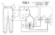
- FIG. 1 is the generally schematic view of the gas mist pressure bath system depending on the first embodiment of the invention.
- the gas mist pressure bath system of this embodiment comprises the gas supply means 11, the liquid supply means 21, the gas mist supply device 31 having the storage 32 composed of a gas mist storing part 32A and a liquid storing part 32B, generating the gas mist by pulverizing and dissolving the liquid and the gas (carbon dioxide, or oxygen, or a mixed gas of carbon dioxide and oxygen), and supplying it under pressurization, the living-body pressure bath cover 41 of forming a space for sealing the supplied gas mist, and the control device 51 for generating and controlling to supply the gas mist.
- the gas mist pressure bath system of this embodiment comprises the gas supply means 11, the liquid supply means 21, the gas mist supply device 31 having the storage 32 composed of a gas mist storing part 32A and a liquid storing part 32B, generating the gas mist by pulverizing and dissolving the liquid and the gas (carbon dioxide, or oxygen, or a mixed
- the liquid supply means 21 is composed of such as a pump and supplies water to the gas mist supply device 31.
- the liquid it is suitable to use water, ionic water, physiological salt solution, ozone water, purified water or sterilized water. Further, these liquids may contain medicines useful to user's diseases or symptoms. For the medicines, enumerated are, for example, anti-allergic agent, anti-inflammatory agent, anti-febrile, anti-fungus agent, anti-influenza virus, carcinostatic substance, anti-hypertensive agent, cosmetic agent, or trichogen.
- these liquids are further possible to generate synergistic effects by coupling with a gas physiological action with single or plurality of menthol having a cooling action; vitamin E accelerating circulation of the blood; vitamin C derivative easily to be absorbed to a skin tissue and having a skin beautifying effect; retinol normalizing a skin heratinizing action and protecting the mucous membrane; anesthetic moderating irritation to the mucous membrane; cyclodextrin removing odor; photocatalysis or a complex of photocatalysis and apatite having disinfection and anti-phlogistic; hyaluronic acid having excellent water holding capacity and a skin moisture retention effect; coenzyme Q10 activating cells and heightening immunization; a seed oil containing anti-oxidation and much nutrient; or propolith having anti-oxidation, anti-fungus, anti-inflummatory agent, pain-killing, anesthetic, and immunity.
- the liquids may be added with ethanol, gluconic acid chlorohexizine, amphoteric surface active agent, benzalkonium chloride, alkyldiamino ether glycin acetate, sodium hypochlorite, acetyl hydroperoxide, sodium sesquicarbonate, silica, povidone-iodine, sodium hydrogen carbonate.
- high density carbonate spring may be added (as examples organic components, sulfate, carbonate, sodium dichloroisocyanurate) having main components of carbonate and organic acid.
- thermometer controlling temperature
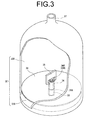
- the storage 32 is, as shown in FIG. 3 , is divided into the gas mist storing part 32A and the liquid storing part 32B by a shielding plate 34.
- the above side (the opening side 33A of the nozzle front end) of the shielding plate 34 is the gas mist storing part 32A of storing the generated gas, while the under side (the bottom side of the storage 32) is the liquid storing part 32B of storing the liquid.
- a nozzle 33 is provided at the bottom center of the storage 32.
- This nozzle 33 is formed to be substantially conic toward an upper part from the bottom side. Its basic end is connected to the gas supply means 11 outside of the device, while its front end projects toward the side of the gas mist storing part 32A, and it is possible to discharge gas from the gas mist storing part 32A.
- the nozzle 33 is connected at its basic end to the gas supply means 11 directly or via a tube, and desirably, a connection portion is composed with such as a connector of one-touch.
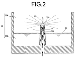
- the suction pipe 36A is formed between the nozzle 33 and a suction pipe-forming member 36 being substantially conic and larger in size than the nozzle 33. That is, as shown in FIG. 2 , by covering the suction pipe-forming member 36 over the nozzle 33, the suction pipe 36A is defined between the outer circumference of the nozzle 33 and the suction pipe-forming member 36. Further, between the basic end of the suction pipe-forming member 36 and the bottom of the liquid storing part 32B, space is defined from which the liquid stored in the liquid storing part 32B is sucked by the suction pipe 36A.
- the front end 36B of the suction pipe-forming member 36 opens nearly a front end opening 33A, and this is so structured that the liquid sucked up along the suction pipe 36A collides with the gas flow discharged from the nozzle 33.
- the baffle 35 is a member which is positioned opposite the front end opening 33A of the nozzle 33 and the front end 36B of the suction pipe-forming member 36, and herein this is connected to the suction pipe-forming member 36.
- the baffle 35 may be structured to connect to the shielding plate 34 or the storage 32.
- the suction pipe-forming member 36 is connected to the shielding plate 34 at a central portion in the vertical direction.
- the outer circumference of the shielding plate 34 is connected to the inside of the storage 32.
- the whole of the gas mist supply device 31 is formed as one-body.
- the shielding plate 34 operates to force liquid upward of the suction pipe-forming member 36 by keeping pressure higher within the liquid storing 32B than that of the gas mist storing part 32A. Therefore, the shielding plate 34 may be secured at a determined position of an inside wall of the liquid storing part 32B, but may be structured to be movable vertically in response to the level of the liquid surface in the liquid storing part 32B. Further, depending on magnification of gas pressure discharged from front end opening 33A, the shielding plate 34 may be absent.
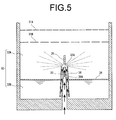
- FIG. 5 above the nozzle 33 in the gas mist storing part 32A, one sheet or plural sheets of plates 31A, 31B (in FIG. 5 , as the example, two sheets) are furnished.
- FIG. 6 shows examples of the plates 31A, 31B.
- the plates 31A, 31B are formed with plural pores, and the generated gas mist is further refined by passing through the pores. Then, with respect to the upper plate 31A and the lower plate 31B, it is preferable that the diameter of the pore in the upper plate 31A is smaller than that of the lower plate 31B.
- the gas from the gas supply means 11 is supplied to the nozzle 33 under a condition of having stored the liquid in the liquid storing part 32B. Then, since the nozzle 33 is reduced in diameter toward the front end, the gas increases flowing speed and discharged. The liquid is sucked upward in the suction pipe 36A owing to negative pressure caused by air current, and is blown up by the air current near the front end opening 33A of the nozzle 33 and collides with the lower end of the baffle 35. By this collision, the liquid is pulverized, mixed with gas and dissolved. Sizes of the mist generated at this time are desirably fine, and concretely, being less than 10 ⁇ m is optimum.
- the generated gas mist spreads over inside of the storing part 32A and is discharged from the gas mist exhaust portion 37 following a gas convection.
- the storing part 32A is shaped in convex dome toward an upper portion having a curved face as shown in FIG. 1 .
- the gas mist exhaust portion 37 is provided at a head top of the dome shape.
- the gas mist discharged from the gas mist exhaust portion 37 is supplied into the living-body pressure bath cover 41 via the gas mist supply pipe 38.
- the gas mist supply pipe 38 is connected to a supply portion 43 of the living-body pressure bath cover 41, and is desirably furnished with a liquid drop removing filter 39 for removing excessive liquid drop attached to the pipe inside.
- the gas mist supply pipe 38 is provided inside with a check valve for checking back-flow of gas mist and gas.
- the liquid in the liquid storing part 32B is supplied from the liquid supply means 21, but it is sufficient to provide such a structure, omitting the liquid supply means 21, in advance containing a liquid (liquid medicine).
- preparing the gas mist supply device 31 having in advance contained the liquid and sealed it is, at using, connected with the gas supply means 11 and the living-body pressure bath cover 41 for taking a gas mist pressure bath. After using, only the gas mist supply device 31 is taken away and disused. Being structured as disposable, the gas mist pressure bath can be taken hygienically and conveniently.
- the supply portion 43 is inside provided with a check valve for checking back flow of the gas mist and the gas.
- the living-body pressure bath cover 41 may be provided with an opening or a valve for exhausting the gas and the gas mist.
- the pressure control may be carried out manually, but as later mentioned, desirably automatically by a control device 51 together with supply control of the gas and the gas mist on the basis of measuring values of the manometer 61.
- a safety valve may be provided for automatically opening a valve when the inside of the living-body pressure bath cover 41 becomes more than a constant pressure.
- the living-body pressure bath cover 41 is inside installed with a manometer 61 for measuring an inside pressure.
- the control device 51 controls supply of the gas mist and the gas on the basis of measuring values of the manometer 61 for maintaining a pressure value within the living-body pressure bath cover 41 to be more than 1 air pressure (more preferably, around 1.02 to 2.5 air pressure).
- the control device 51 controls or stops the supply of the gas from the gas supply means 11, or exhausts the gas or the gas mist from the living-body pressure bath cover 41.
- the living-body pressure bath cover 41 is inside installed with a thermometer 62 for measuring an inside temperature within the living-body pressure bath cover 41.
- the control device 51 performs on-off of a heater installed in the liquid supply means 21 on the basis of measuring values of a manometer 62 for maintaining a predetermined temperature (for example, around 38°C) bringing about warm bath effects within the living-body pressure bath cover 41.
- the living-body pressure bath cover 41 has, around its opening, a stopper 42 for attaching to and detaching from the living body (herein, as the example, the lower extremity) and stopping leakage of the gas mist and the gas.
- the stopper 42 is suitably composed of, e.g., a face stretching fastener, or may have a sole string or rubber or their combination.
- the inside that of the stopper 42 may have a material attaching to the user' s skin.
- the adhesive material is preferably, e.g., a visco-elastic gel of polyurethane or silicone rubber. Further, this adhesive material is detachably used and exchangeable each time or if viscosity becomes weak.
- the control device 51 is composed of a computer having CPU, memory and display. This device performs various kinds of controls such as pressure control or on-off switch of the gas from the gas supply means 11, supply pressure or temperature of the liquid from the liquid supply means 21, on-off switch of the gas mist, on-off switch of the gas mist in order to perform the gas mist pressure bath under an optimum condition.
- controls such as pressure control or on-off switch of the gas from the gas supply means 11, supply pressure or temperature of the liquid from the liquid supply means 21, on-off switch of the gas mist, on-off switch of the gas mist in order to perform the gas mist pressure bath under an optimum condition.
- the living-body pressure bath cover 41 is secured to the living body (herein, as the example, the lower extremity) and closed.
- the liquid storing part 32B of the gas mist supply device 31 a liquid of a predetermined amount is in advance poured, and next, the gas is supplied from the gas supply means 11 to the nozzle, thereby to generate the gas mist.
- the control device 51 controls the supplying pressure, amount, temperature and others of the liquid and the gas.
- the generated gas mist is supplied from the supply portion 43 into the living-body pressure bath cover 41.
- the gas is not supplied into the nozzle 33, but directly supplied into the gas mist storing part 32A.
- the control device 51 once stops supply of the gas mist or the gas and under this condition the gas mist pressure bath is carried out.
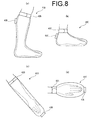
- FIG. 8 shows the various shaped examples of the living-body pressure bath covers 41 for covering further limited parts of the living body.
- FIG. 8 (a) is a living-body pressure bath cover 41B for one-side lower extremity (lower part under a knee) of the living body.
- the living-body pressure bath cover 41B has a stopper 42B at its opening part and a supply portion 43B for introducing the gas mist and the gas inside.
- FIG. 8(b) is a living-body pressure bath cover 41C for a foot of the living body.
- the living-body pressure bath cover 41C has a stopper 42C at its opening part and a supply portion 43C for introducing inside the gas mist and the gas.
- FIG. 8 (b) is a living-body pressure bath cover 41C for a foot of the living body.
- the living-body pressure bath cover 41C has a stopper 42C at its opening part and a supply portion 43C for introducing inside the gas mist and the gas.
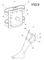
- FIG. 9 shows a patch shaped living-body pressure bath cover 41F.
- FIG. 9(a) is a view showing an outline of the patch shaped living-body pressure bath cover 41F.
- FIG. 9 (b) is a view showing an external appearance when attaching the patch shaped living-body pressure bath cover 41F to the living body (herein, lower extremity of the living body).
- the living-body pressure bath cover 41F is composed of a cover part 45F for covering the skin and mucous membrane of the living body, a stopper 42F provided at the margin of the cover part 45F and directly attached to the skin and mucous membrane of the living body, a supply portion 43F for supplying the gas mist and the gas into a space defined by the cover part 45F and the stopper 42F, and fasteners 44F made of belts or strings for fastening the cover part 45F to the living body.
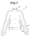
- the living-body pressure bath covers 41 other than the examples shown in FIG.s 7 to 9 , various shapes may be assumed. In sum, if forming the space for sealing the gas mist and the gas inside, any shape is sufficient. An exhaust portion may be formed for exhausting the gas mist and the gas from the inside of the living-body pressure bath covers 41. In addition, the invention may be applied not only to the human living body but to animals.
- the control device 51 may supply the gas mist into the living body pressure bath cover 41 intermittently at fixed rhythm. As to the pressurizing interval at such a case, if synchronizing with pulsations, the effects are more heightened.
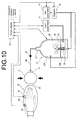
- FIG. 10 is the whole schematic view of the gas mist pressure bath system depending on the second embodiment of this invention. This embodiment will explain the gas mist pressure bath system further having a pressurizing means for simplifying pressurization within the living-body pressure bath cover. As to the same parts as those of the first embodiment shown in FIG. 1 , the same numerals will be given, and detailed explanation will be omitted.
- the gas mist pressure bath system of this embodiment has a living-body pressure bath cover 81 forming a space into which the gas mist and the gas are sealed and a pressurizing part (gas storage) 71 connecting the living-body pressure bath cover 81 and pressurizing therein.
- the living-body pressure bath cover 81 has almost the same structure of the living-body pressure bath cover 41 of the first embodiment, and has a stopper 82 and a gas mist and gas supply portion 83, provided herein that the supply portion 83 is connected to the pressurizing part 71.
- the example hereof illustrates the living-body pressure bath cover 81 of a shape for covering a hand of the human living body.
- the pressurizing part 71 is the hollow gas storage connecting the living-body pressure bath cover 81 and pressurizing therein.
- the pressurizing part 71 is connected to the supply portion 83 of the living-body pressure bath cover 81 and has also a supply portion 72 of itself from which the gas mist or the gas are supplied therein.
- the supply portion 72 of the pressurizing part 71 is also provided with the check valve for checking back flow of the gas mist and the gas.
- the pressurizing part 71 may be structured as pressing manually, and mechanically by controlling the control means 51 using a driving device. As mentioned above, pressurization in the gas mist pressure bath heightens effects by performing interval pressurization in pulse, and so the pressurizing part 71 may be pressed intermittently. The pressurizing interval heightens effects by synchronizing with pulsation of pulse.
- the living-body pressure bath cover 81 is secured to the living body (herein, as the example, the living-body's hand) and closed.
- the liquid storing part 32B of the gas mist supply device 31 a liquid of a predetermined amount is in advance poured, and next, the gas is supplied from the gas supply means 11 to the nozzle 33, thereby to generate the gas mist.
- the control device 51 controls the supplying pressure, amount, temperature and others of the liquid and the gas.
- the generated gas mist is supplied from the supply portion 83 via the pressurizing part 71 into the living-body pressure bath cover 81.
- the gas mist is not supplied into the nozzle 33, but directly supplied into the gas mist storing part 32A.
- the control device 51 so controls that the inside of the living-body pressure bath cover 81 is to be at an optimum temperature (for example, around 38°C) from the measuring values of the thermometer 62.
- the pressurizing part 71 is pressurized as crushed.
- the gas mist or the gas in the pressurizing part 71 are exhausted into the living-body pressure bath cover 81, and the inside of the living-body pressure bath cover 81 is pressurized moderately (around 1.02 to 2.5 air pressure) and the gas mist pressure bath is carried out.
- the living-body pressure bath cover 81 is applied to various parts of the living body, many shapes may be used, provided in this embodiment that shapes (size) must be easily pressurized by the pressurizing part 71. This substantially depends on the dimension of the pressurizing part 71. Actually, so far as pressurizing means are any one, the pressurizing part 71 is desirably compact as not demanding large spaces, and accordingly, the living-body pressure bath cover is also desirably applied to comparatively compact objects (covering limited parts of the living body).
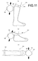
- FIG.s 11 and 12 show examples of the living-body pressure bath cover 81 and the pressurizing part 71 connected thereto.
- FIG. 11(a) is a living-body pressure bath cover 81A for one-side lower extremity (lower part under a knee) of the living body.
- the living-body pressure bath cover 81A has a stopper 82A at its opening part and a supply portion 83A for introducing inside the gas mist and the gas.
- the supply portion 83A is connected to the pressurizing part 71, and the gas mist and the gas are supplied into the living-body pressure bath cover 81A through a supply portion 72A of a pressurizing part 71A.
- FIG. 11(a) is a living-body pressure bath cover 81A for one-side lower extremity (lower part under a knee) of the living body.
- the living-body pressure bath cover 81A has a stopper 82A at its opening part and a supply portion 83A for introducing inside the gas mist
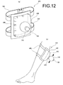
- FIG. 12 shows a patch shaped living-body pressure bath covers 81D.
- FIG. 12(a) is a view showing an outline of the patch shaped living-body pressure bath covers 81D.
- FIG. 12 (b) is a view showing an external appearance when attaching the patch shaped living-body pressure bath covers 81D to the living body (herein, lower extremity of the living body).
- the living-body pressure bath covers 81D is composed of a cover part 85D for covering the skin and mucous membrane of the living body, a stopper 82D provided at the margin of the cover part 85D and directly attached to the skin and mucous membrane of the living body, a supply portion 83D for supplying the gas mist and the gas into a space defined by the cover part 85D and the stopper 82D, and fasteners 84D made of belts or strings for fastening the cover part 85D to the living body.
- the supply portion 83D is connected to a pressurizing part 71D, and through a supply portion 72D of a pressurizing part 71D, the gas mist and the gas are supplied into the living-body pressure bath cover 81D.
- An exhaust portion may be formed for exhausting the gas mist and the gas from the inside of the living-body pressure bath cover 81.
- the invention may be applied not only to the human living body but to animals.
- the pressurizing part 71 is the hollow gas storage connected to the living-body pressure bath cover 81, and so far as materials of easily pressurizing as crushing externally the living-body pressure bath cover 81 itself, any materials are sufficient.
- FIG. 13 is the whole schematic view of the gas mist pressure bath system depending on the third embodiment of this invention. This embodiment will explain the gas mist pressure bath system further having a means for charging generated mist. As to the same parts as those of the first embodiment shown in FIG. 1 , the same numerals will be given, and detailed explanation will be omitted.
- the gas mist pressure bath system of this embodiment is arranged with an electrode 92 at the gas mist exhaust portion 37 of the gas mist supply device 31.
- the electrode 92 is connected to a source device 91, and the control device 51 sets voltage values and performs on-off control.
- the electrode 92 supplies an electric charge (minus charge is desirable) when exhausting the mist generated by the gas mist supply device 31 from the gas mist exhaust portion 37.
- the mist is made turn out charged so that adhesion to a charged material can be heightened. For example, if adhesion to the skin and the mucous membrane of the living body, an effect of increasing absorption of the gas by the mist is further heightened, and if the mist contains the above mentioned medicines, penetration into the skin and the mucous membrane can be accelerated.
- the living-body pressure bath cover 41 is secured to the living body (herein, as the example, the lower extremity) and closed.
- the liquid storing part 32B of the gas mist supply device 31 a liquid of a predetermined amount is in advance poured, and next, the gas is supplied from the gas supply means 11 to the nozzle 33, thereby to generate the gas mist.
- the control device 51 controls the gas supplying pressure, amount, or the liquid supplying amount, temperature and others.
- the control device 51 turns on the source device 91, and supplies electric charge from an electrode 92 to the mist.
- the generated gas mist is supplied from the supply portion 43 into the living-body pressure bath cover 41.
- the gas is not supplied into the nozzle 33, but directly supplied into the gas mist storing part 32A.
- the control device 51 once stops supply of the gas mist or the gas and under this condition the gas mist pressure bath is carried out.
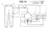
- FIG. 14 is the whole schematic view of the gas mist pressure bath system depending on the fourth embodiment of this invention.
- This embodiment will explain the gas mist pressure bath system further having a liquid pressurizing means for pressurizing the liquid from the liquid supply means and sending it to the gas mist supply means.
- a liquid pressurizing means for pressurizing the liquid from the liquid supply means and sending it to the gas mist supply means.
- the same numerals will be given, and detailed explanation will be omitted.
- the gas mist pressure bath system of this embodiment is provided with the liquid pressurizing means 101 for pressurizing the liquid and sending it to the gas mist supply device 31.
- the liquid pressurizing means 101 is composed of a pump for pressurizing the liquid from the liquid supply means 21 and sending it to the liquid storing part 32B of the gas mist supply device 31. By pressurizing the liquid, it makes easy to pressurize and supply of the gas mist of the gas mist supply device 31. Adjustment of supplying pressure in the liquid pressurizing means 101 is carried out by the control device 51.
- the living-body pressure bath cover 41 is secured to the living body (herein, as the example, the lower extremity) and closed.
- a liquid of a predetermined amount is in advance poured via the liquid pressurizing means 101.
- the control device 51 controls the liquid and gas supplying pressure, amount, or the liquid supplying amount, temperature and others.
- the control device 51 turns on the source device 91, and supplies electric charge from an electrode 92 to the mist.
- the generated gas mist is supplied from the supply portion 43 into the living-body pressure bath cover 41.
- the gas is not supplied into the nozzle 33, but directly supplied into the gas mist storing part 32A.
- the control device 51 once stops supply of the gas mist or the gas and under this condition the gas mist pressure bath is carried out.
- the above mentioned explanation has been made with the example of the lower extremities of the living body, and the invention is applicable to various parts. Then, the optimum gas mist pressure bath is performed using the living-body pressure bath cover 41 meeting object parts of the living body.
- the gas mist pressure bath system it is possible to control the amount, pressure and other of the gas mist within the living-body pressure bath cover by the control device, and so the gas mist pressure bath can be always carried out under the optimum condition.
- pressurization into the living-body pressure bath cover is easy, the gas skin-pass absorption can be more efficiently performed.
Landscapes
- Health & Medical Sciences (AREA)
- Public Health (AREA)
- Veterinary Medicine (AREA)
- Life Sciences & Earth Sciences (AREA)
- Animal Behavior & Ethology (AREA)
- General Health & Medical Sciences (AREA)
- Epidemiology (AREA)
- Pain & Pain Management (AREA)
- Physical Education & Sports Medicine (AREA)
- Rehabilitation Therapy (AREA)
- Chemical & Material Sciences (AREA)
- Inorganic Chemistry (AREA)
- Medicinal Chemistry (AREA)
- Pharmacology & Pharmacy (AREA)
- Devices For Medical Bathing And Washing (AREA)
Applications Claiming Priority (5)
| Application Number | Priority Date | Filing Date | Title |
|---|---|---|---|
| JP2009026767 | 2009-02-06 | ||
| JP2009026769 | 2009-02-06 | ||
| JP2009026768 | 2009-02-06 | ||
| JP2009026766 | 2009-02-06 | ||
| PCT/JP2010/051492 WO2010090210A1 (ja) | 2009-02-06 | 2010-02-03 | ガスミスト圧浴システム |
Publications (1)
| Publication Number | Publication Date |
|---|---|
| EP2332509A1 true EP2332509A1 (en) | 2011-06-15 |
Family
ID=42542103
Family Applications (1)
| Application Number | Title | Priority Date | Filing Date |
|---|---|---|---|
| EP10738541A Withdrawn EP2332509A1 (en) | 2009-02-06 | 2010-02-03 | Gas mist pressure bath system |
Country Status (8)
| Country | Link |
|---|---|
| US (1) | US20110060257A1 (ja) |
| EP (1) | EP2332509A1 (ja) |
| JP (1) | JP4922459B2 (ja) |
| KR (1) | KR20110118124A (ja) |
| CN (1) | CN102046135B (ja) |
| AU (1) | AU2010211679B2 (ja) |
| BR (1) | BRPI1011360A2 (ja) |
| WO (1) | WO2010090210A1 (ja) |
Families Citing this family (10)
| Publication number | Priority date | Publication date | Assignee | Title |
|---|---|---|---|---|
| JPWO2012086636A1 (ja) * | 2010-12-20 | 2014-05-22 | 中村 正一 | 生体の虚血領域の血行状態を改善又は促進するための炭酸ガスミスト圧浴方法及び炭酸ガスミスト圧浴装置 |
| US9271894B2 (en) * | 2010-12-20 | 2016-03-01 | Advance Biotron Co., Ltd. | Carbon dioxide gas mist pressure bath apparatus for preventing, improving or curing myocardial infarction |
| JP5102377B2 (ja) * | 2011-01-21 | 2012-12-19 | 正一 中村 | ガスミスト圧浴システム |
| JP5743587B2 (ja) * | 2011-02-17 | 2015-07-01 | 中村 正一 | ガスミスト圧浴システム |
| EP2532341A1 (en) * | 2011-06-07 | 2012-12-12 | Burghardt Krebber | Kit of parts for the treatment of infectious disease |
| KR20140095966A (ko) * | 2011-11-04 | 2014-08-04 | 쇼이치 나카무라 | 가스 미스트 압욕 시스템 |
| CA2856196C (en) | 2011-12-06 | 2020-09-01 | Masco Corporation Of Indiana | Ozone distribution in a faucet |
| CN103893906B (zh) * | 2014-04-02 | 2016-01-20 | 宁波江北怡和工业设计有限公司 | 一种背部敷药器 |
| CN103893905B (zh) * | 2014-04-02 | 2016-01-27 | 宁波江北怡和工业设计有限公司 | 背部敷药器 |
| US11458214B2 (en) | 2015-12-21 | 2022-10-04 | Delta Faucet Company | Fluid delivery system including a disinfectant device |
Family Cites Families (25)
| Publication number | Priority date | Publication date | Assignee | Title |
|---|---|---|---|---|
| US3826255A (en) * | 1972-06-22 | 1974-07-30 | Hudson Oxygen Therapy Sales Co | Intermittent positive pressure breathing manifold |
| JPS61217132A (ja) * | 1985-03-22 | 1986-09-26 | 松下電工株式会社 | 血圧計 |
| US4792097A (en) * | 1987-03-31 | 1988-12-20 | Mallinckrodt, Inc. | Non-sputtering nebulizer |
| US4772259A (en) * | 1987-06-12 | 1988-09-20 | Ballard Medical Products | Hyperbaric oxygenation apparatus and methods |
| US5054478A (en) * | 1989-04-21 | 1991-10-08 | Trudell Medical | Nebulizer |
| JP2979416B2 (ja) * | 1989-10-30 | 1999-11-15 | カシオ計算機株式会社 | キー入力装置 |
| JPH07171189A (ja) | 1993-12-17 | 1995-07-11 | Matsushita Electric Works Ltd | 血行促進装置 |
| US5823179A (en) * | 1996-02-13 | 1998-10-20 | 1263152 Ontario Inc. | Nebulizer apparatus and method |
| JP3844384B2 (ja) * | 1997-08-07 | 2006-11-08 | 株式会社ファイン | 気体処理装置 |
| WO2003009788A1 (de) * | 2001-07-25 | 2003-02-06 | Zimmer Elektromedizin Gmbh | Thermischer applikator und applikatorsystem |
| TW580384B (en) * | 2002-07-01 | 2004-03-21 | Neochemir Inc | Carbon dioxide administrating device |
| JP2005205163A (ja) * | 2003-06-30 | 2005-08-04 | Pijon:Kk | 理美容機用ミスト噴霧装置 |
| JP3981711B2 (ja) * | 2003-07-28 | 2007-09-26 | 有限会社ネクスティア | 二酸化炭素治療装置 |
| JP2006026022A (ja) * | 2004-07-14 | 2006-02-02 | Aglex Inc | 理美容用蒸気発生装置 |
| JP2006062024A (ja) * | 2004-08-26 | 2006-03-09 | Ebara Corp | ミスト生成装置 |
| JP2006322683A (ja) * | 2005-05-20 | 2006-11-30 | Mitsubishi Heavy Ind Ltd | 蒸気発生器 |
| JP2007014482A (ja) * | 2005-07-06 | 2007-01-25 | Hitachi Ltd | 人工炭酸泉製造装置 |
| WO2007100857A2 (en) * | 2006-02-28 | 2007-09-07 | Vortexx Group, Inc. | Nozzle that produce angular momentum and methods for making and using same |
| RU2468785C2 (ru) * | 2006-10-18 | 2012-12-10 | Неокемир Инк. | Устройство для наружного введения диоксида углерода |
| JP2009018136A (ja) * | 2007-06-12 | 2009-01-29 | Tatsuo Okazaki | 炭酸温水による美容方法および機器 |
| JP3144718U (ja) * | 2008-06-27 | 2008-09-11 | 正一 中村 | 炭酸ガス浴用カバー |
| JP3144717U (ja) * | 2008-06-27 | 2008-09-11 | 正一 中村 | 炭酸ガス浴用カバー |
| CN101925340B (zh) * | 2008-06-27 | 2014-10-08 | 中村正一 | 气雾压浴装置 |
| JP3150692U (ja) * | 2009-03-10 | 2009-05-28 | 中村 正一 | ガスミスト圧浴用カバー |
| JP3150690U (ja) * | 2009-03-10 | 2009-05-28 | 中村 正一 | ガスミスト圧浴用カバー |
-
2010
- 2010-02-03 KR KR1020117012009A patent/KR20110118124A/ko not_active Application Discontinuation
- 2010-02-03 US US12/736,731 patent/US20110060257A1/en not_active Abandoned
- 2010-02-03 BR BRPI1011360A patent/BRPI1011360A2/pt not_active IP Right Cessation
- 2010-02-03 WO PCT/JP2010/051492 patent/WO2010090210A1/ja active Application Filing
- 2010-02-03 EP EP10738541A patent/EP2332509A1/en not_active Withdrawn
- 2010-02-03 JP JP2010549489A patent/JP4922459B2/ja not_active Expired - Fee Related
- 2010-02-03 AU AU2010211679A patent/AU2010211679B2/en not_active Ceased
- 2010-02-03 CN CN201080001687.0A patent/CN102046135B/zh not_active Expired - Fee Related
Non-Patent Citations (1)
| Title |
|---|
| See references of WO2010090210A1 * |
Also Published As
| Publication number | Publication date |
|---|---|
| CN102046135B (zh) | 2014-02-19 |
| WO2010090210A1 (ja) | 2010-08-12 |
| US20110060257A1 (en) | 2011-03-10 |
| KR20110118124A (ko) | 2011-10-28 |
| JP4922459B2 (ja) | 2012-04-25 |
| AU2010211679A1 (en) | 2010-08-12 |
| JPWO2010090210A1 (ja) | 2012-08-09 |
| BRPI1011360A2 (pt) | 2016-03-15 |
| CN102046135A (zh) | 2011-05-04 |
| AU2010211679B2 (en) | 2014-01-16 |
Similar Documents
| Publication | Publication Date | Title |
|---|---|---|
| AU2010211679B2 (en) | Gas mist pressure bath system | |
| US8230853B2 (en) | Gas mist pressure bath system | |
| US8505532B2 (en) | Carbon dioxide mist pressure bath system | |
| EP2246027A1 (en) | Pressurized carbon dioxide-containing mist bathing system | |
| US8585633B2 (en) | Gas mist pressure bath system | |
| US8961478B2 (en) | Gas mist pressure bathing system | |
| EP2279721A1 (en) | Pressurized gas mist bathing system | |
| US9278204B2 (en) | Pressurized gas mist bathing system | |
| US9101526B2 (en) | Gas mist pressure bathing system | |
| EP2260826A1 (en) | Gas mist pressure bath system | |
| US8905982B2 (en) | Gas mist pressure bath system | |
| US9713569B2 (en) | Pressurized gas mist bathing system |
Legal Events
| Date | Code | Title | Description |
|---|---|---|---|
| PUAI | Public reference made under article 153(3) epc to a published international application that has entered the european phase |
Free format text: ORIGINAL CODE: 0009012 |
|
| 17P | Request for examination filed |
Effective date: 20101112 |
|
| AK | Designated contracting states |
Kind code of ref document: A1 Designated state(s): AT BE BG CH CY CZ DE DK EE ES FI FR GB GR HR HU IE IS IT LI LT LU LV MC MK MT NL NO PL PT RO SE SI SK SM TR |
|
| AX | Request for extension of the european patent |
Extension state: AL BA RS |
|
| DAX | Request for extension of the european patent (deleted) | ||
| STAA | Information on the status of an ep patent application or granted ep patent |
Free format text: STATUS: THE APPLICATION HAS BEEN WITHDRAWN |
|
| 18W | Application withdrawn |
Effective date: 20150109 |