EP2331844B1 - Tendeur compact avec amortissement durable - Google Patents
Tendeur compact avec amortissement durable Download PDFInfo
- Publication number
- EP2331844B1 EP2331844B1 EP09817152.3A EP09817152A EP2331844B1 EP 2331844 B1 EP2331844 B1 EP 2331844B1 EP 09817152 A EP09817152 A EP 09817152A EP 2331844 B1 EP2331844 B1 EP 2331844B1
- Authority
- EP
- European Patent Office
- Prior art keywords
- spring
- base
- tensioner assembly
- arm
- stem
- Prior art date
- Legal status (The legal status is an assumption and is not a legal conclusion. Google has not performed a legal analysis and makes no representation as to the accuracy of the status listed.)
- Active
Links
- 238000013016 damping Methods 0.000 title claims abstract description 58
- 230000000712 assembly Effects 0.000 description 10
- 238000000429 assembly Methods 0.000 description 10
- 239000000428 dust Substances 0.000 description 6
- 238000000034 method Methods 0.000 description 5
- 239000000463 material Substances 0.000 description 4
- 229910000831 Steel Inorganic materials 0.000 description 3
- 230000007423 decrease Effects 0.000 description 3
- 238000009826 distribution Methods 0.000 description 3
- 239000010959 steel Substances 0.000 description 3
- 239000004677 Nylon Substances 0.000 description 2
- 230000005540 biological transmission Effects 0.000 description 2
- 230000001419 dependent effect Effects 0.000 description 2
- 238000004512 die casting Methods 0.000 description 2
- 238000009434 installation Methods 0.000 description 2
- 229920001778 nylon Polymers 0.000 description 2
- 239000012858 resilient material Substances 0.000 description 2
- XAGFODPZIPBFFR-UHFFFAOYSA-N aluminium Chemical compound [Al] XAGFODPZIPBFFR-UHFFFAOYSA-N 0.000 description 1
- 229910052782 aluminium Inorganic materials 0.000 description 1
- 230000006835 compression Effects 0.000 description 1
- 238000007906 compression Methods 0.000 description 1
- 238000010586 diagram Methods 0.000 description 1
- 238000004519 manufacturing process Methods 0.000 description 1
- 230000000750 progressive effect Effects 0.000 description 1
Images


Classifications
-
- F—MECHANICAL ENGINEERING; LIGHTING; HEATING; WEAPONS; BLASTING
- F16—ENGINEERING ELEMENTS AND UNITS; GENERAL MEASURES FOR PRODUCING AND MAINTAINING EFFECTIVE FUNCTIONING OF MACHINES OR INSTALLATIONS; THERMAL INSULATION IN GENERAL
- F16H—GEARING
- F16H7/00—Gearings for conveying rotary motion by endless flexible members
- F16H7/08—Means for varying tension of belts, ropes, or chains
- F16H7/10—Means for varying tension of belts, ropes, or chains by adjusting the axis of a pulley
- F16H7/12—Means for varying tension of belts, ropes, or chains by adjusting the axis of a pulley of an idle pulley
- F16H7/1209—Means for varying tension of belts, ropes, or chains by adjusting the axis of a pulley of an idle pulley with vibration damping means
- F16H7/1218—Means for varying tension of belts, ropes, or chains by adjusting the axis of a pulley of an idle pulley with vibration damping means of the dry friction type
-
- F—MECHANICAL ENGINEERING; LIGHTING; HEATING; WEAPONS; BLASTING
- F16—ENGINEERING ELEMENTS AND UNITS; GENERAL MEASURES FOR PRODUCING AND MAINTAINING EFFECTIVE FUNCTIONING OF MACHINES OR INSTALLATIONS; THERMAL INSULATION IN GENERAL
- F16H—GEARING
- F16H7/00—Gearings for conveying rotary motion by endless flexible members
- F16H7/08—Means for varying tension of belts, ropes, or chains
- F16H2007/0802—Actuators for final output members
- F16H2007/081—Torsion springs
-
- F—MECHANICAL ENGINEERING; LIGHTING; HEATING; WEAPONS; BLASTING
- F16—ENGINEERING ELEMENTS AND UNITS; GENERAL MEASURES FOR PRODUCING AND MAINTAINING EFFECTIVE FUNCTIONING OF MACHINES OR INSTALLATIONS; THERMAL INSULATION IN GENERAL
- F16H—GEARING
- F16H7/00—Gearings for conveying rotary motion by endless flexible members
- F16H7/08—Means for varying tension of belts, ropes, or chains
- F16H2007/0889—Path of movement of the finally actuated member
- F16H2007/0893—Circular path
Definitions
- the present invention generally relates to a tensioner that is employed to tension an endless power transmitting element.
- a tensioner assembly in accordance with the preamble of claim 1 is known from DE102006017287A .
- Mechanical tensioners are employed to automatically control the tension in an endless power transmitting element, such as a belt or a chain.
- mechanical tensioners employ an arm that pivots about a base and a torsion spring that biases the arm in a predetermined rotational direction. Torsional damping is sometimes needed to ensure that the endless power transmitting element, or a component driven by the endless power transmitting system, is not overstressed.
- damping tensioners can be costly to manufacture and/or do not provide for consistent damping performance throughout the life of the tensioner and/or can subject a pivot bushing the arm and the base to relatively high forces, which can result in pulley misalignment as the pivot bushing wears. Accordingly, there remains a need in the art for an improved damping tensioner.
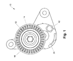
- Figure 1 is a top plan view of a tensioner assembly constructed in accordance with the teachings of the present disclosure
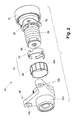
- Figures 2 and 3 are exploded perspective views of the tensioner assembly of Figure 1 ;
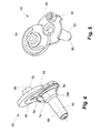
- Figures 4 and 5 are perspective views of a portion of the tensioner assembly of Figure 1 illustrating the arm in more detail;
- Figure 6 is a perspective view of a portion of the tensioner assembly of Figure 1 illustrating the arm and the spring in greater detail;
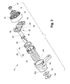
- Figure 7 is a sectional view of the tensioner assembly of Figure 1 ;
- Figures 8 and 9 are sectional views of a tensioner similar to that of Figure 1 but illustrating the tensioner assemblies with differently sized damping elements;
- Figure 10 and 11 are sectional views of the tensioner assembly of Figure 1 illustrating the damping element and the spring relative to the brake drum when the damping element is new ( Fig. 10 ) and when the damping element is wom ( Fig. 11 );
- Figure 12 is a view of a portion of the tensioner assembly of Figure 1 schematically illustrating the spring load and the grounding force as applied to the tensioner assembly;
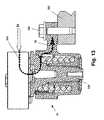
- Figure 13 is a section view of the tensioner assembly of Figure 1 schematically illustrating the path along which the hub load is transmitted through the tensioner assembly to the base;
- Figure 14 is a section view of a prior art tensioner assembly schematically illustrating the path along which the hub load is transmitted through the prior art tensioner assembly to its mounting base;
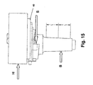
- Figures 15 and 16 are free-body diagrams of a portion of the tensioner assembly of Figure 1 that schematically illustrate the hub load, the spring reaction force and the bushing load that are applied to an illustrated portion of the tensioner assembly;
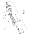
- FIG 17 is an exploded perspective view of another tensioner assembly constructed in accordance with the teachings of the present disclosure.
- Figure 18 is a perspective view of a portion of the tensioner assembly of Figure 17 illustrating the arm and the spring in greater detail;
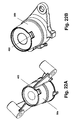
- Figures 19 and 20 are views of a portion of the tensioner of Figure 1 schematically depicting the distribution of damping force under different load conditions;
- Figures 21 A and 21 B are plan views of the arms of two tensioner assemblies in a family of tensioner assemblies, the arms being configured with features that permit a common set of tooling and/or assembly steps to be employed in the assembly of the tensioner assemblies;
- Figure 22A and 22B are perspective view of the bases of two tensioner assemblies in a family of tensioner assemblies, the bases being configured with features that permit a common set of tooling and/or assembly steps to be employed in the assembly of the tensioner assemblies;
- Figures 23A through 23C are perspective views illustrating an assembly process in which features formed onto the base and arm of the tensioner assembly are engaged to one another to maintain the arm of the tensioner assembly in a predetermined axial position relative to the base during a portion of the assembly process;
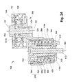
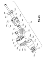
- FIG. 24 is a sectional view of another tensioner assembly constructed in accordance with the teachings of the present disclosure.
- Figure 25 is an exploded perspective view of the tensioner assembly of Figure 24 .
- the tensioner assembly 10 can include a fastener 12, a dust shield 14, a wheel 16, a bearing 18, an arm 20, a pivot bushing 22, a damping mechanism 23 (which can comprise a sleeve 24 and a damping element 26), a spring 28, a bracket or base 30, a thrust washer 32 and a thrust plate 34.
- the fastener 12, the dust shield 14, the bearing 18 and the thrust washer 32 can be generally conventional in their configuration and as such, need not be discussed in detail herein.
- the arm 20 can be unitarily formed in a suitable process, such as die casting, and can define an arm member or portion 40 and a stem member or portion 42.
- the arm portion 40 can include a bearing mount 50, a lifting member 52, a spring reaction member 54 and a spring support 56, while the stem portion 42 can include a stem 60.
- the bearing mount 50 can be formed onto a first side of the arm portion 40 and can be configured to be received into an inner bearing race 18-1 of the bearing 18 to support the wheel 16 for rotation about a first axis 66.
- the fastener 12 can be threadably engaged to the bearing mount 50 and can cooperate with the dust shield 14 and the bearing 18 to rotatably mount the wheel 16 to the arm portion 40.
- the lifting member 52 can be formed on the first side of the arm portion 40 and can be configured to be engaged by a tool (not shown) to pivot the arm portion 40 about a second axis 68 that extends through the stem portion 42.
- a tool not shown
- the wheel 16 has been illustrated in the particular example as being a generally cylindrically shaped roller, it will be appreciated that the wheel could include teeth, grooves and/or other features. Accordingly, it will be appreciated that the wheel 16 could be a sprocket or a pulley in the alternative.
- the spring reaction member 54 can be offset from the second axis 68 and can be configured to engage the spring 28 to permit the spring 28 to apply a force to the arm portion 40 that tends to rotate the arm portion 40 about the second axis 68.
- the spring reaction member 54 is a block-like nub having an end face 74 that is configured to abut an end face 76 of a first helical coil 78 of the spring 28. It will be appreciated, however, that the spring reaction member 54 and the spring 28 can be configured somewhat differently as will be discussed in detail, below.
- the spring support 56 can be helically shaped and can be configured to support the first helical coil 78 of the spring 28.
- the stem 60 can be disposed on a side of the arm portion 40, such as the side opposite the bearing mount 50, and can be configured to receive the pivot bushing 22 and the spring 28.
- the stem 60 is tapered (i.e., the stem 60 has a frusto-conical shape) such that it converges with increasing distance from the arm portion 40.
- the pivot bushing 22 can have a tapered configuration that is configured to be received over the stem 60 and matingly received into a bushing aperture 84 formed in the base 30.
- the bushing aperture 84 also employs a tapered (i.e., frusto-conical) shape. It will be appreciated from this disclosure that the pivot bushing 22 can support the arm 20 relative to the base 30 for rotation about the second axis 68.
- the sleeve 24 can be formed of an appropriate material, such as steel, and can be configured to engage the spring 28 and distribute the force exerted by the spring 28 onto the damping element 26.
- the sleeve 24 includes a window 90 into which the spring reaction member 54 can be received to thereby non-rotatably couple the sleeve 24 to the arm 20.
- the sleeve 24 can be shaped to distribute load between the spring 28 and the damping element 26 in a desired manner.
- the damping element 26 can be formed of a resilient material, such as an unfilled (non-reinforced) nylon so as to flexibly conform to the interior surface of a cylindrically-shaped brake drum aperture 100 formed in a brake drum 101 that can be coupled to the base 30.
- the damping element 26 can be non-rotatably engaged to the sleeve 24, as well as received into the brake drum aperture 100.
- the damping element 26 can contact the circumferential surface 102 of the brake drum aperture 100 to dampen the torque that is transmitted about the second axis 68.
- the surface 104 of the damping element 26 that contacts the circumferential surface 102 of the brake drum aperture 100 can be configured in a desired manner to control the distribution of force at given points along the surface 104 of the damping element 26.
- tensioner assembly 10-1 is illustrated to including a damping element 26-1 that is relatively taller than the damping element 26-2 of the tensioner assembly 10-2.
- contact over a relatively smaller area can facilitate cost reduction of the tensioner assembly (through a reduction of material to form the damping element) but can increase the load on the damping element. Configuration of the tensioner assembly in this manner permits the surface area of the sleeve and/or damping element to be easily tailored to a given situation.
- the curvature of the spring 28 can vary as a function of torque transmitted through the spring 28.
- the arc X of contact between spring 28 and damping mechanism 23 can vary (i.e., increase or decrease, respectively) such that the area over which the load is transmitted between the damping mechanism 23 and the base 30 can correspondingly increase or decrease, respectively. Accordingly, a desired range of pressure on the damping element 26 may be maintained.
- the spring 28 can be received into a spring pocket 110 formed in the base 30 concentric with the stem 60.
- An end 112 ( Fig. 6 ) of the spring 28 opposite the spring reaction member 54 ( Fig. 4 ) can engage the base 30 in a desired manner.
- the spring pocket 110 can include a groove 114 into which a last coil 116 of the spring 28 can be received and the groove 114 can terminate at an end face (not specifically shown) that is perpendicular to the axis of the wire that forms the last coil 116 so that an end face 112 ( Fig. 6 ) of the last coil 116 can be abutted against the end face of the groove 114
- the groove 114 can be configured to support the last coil 116 in a desired manner at one or more locations along its (helical) length.
- the base 30 can include a plurality of mounting bosses 130 that are configured to receive threaded fasteners 132 when the base 30 is fixedly coupled to a structure, such as an engine block (not shown).
- the base 30 can be formed of a desired material, such as aluminum, in an appropriate process, such as die casting.
- the thrust plate 34 can be fixedly coupled to an end of the stem 60 that extends through the base 30 so that the arm 20 is axially fixed but rotatable relative to the base 30.
- the thrust washer 32 which can be received between the thrust plate 34 and the base 30, can be employed to control the friction between the base 30 and the thrust plate 34, as well as to control the compressive force acting on the spring 28.
- the arm 20 can be rotated about the second axis 68 to apply tension to an endless power transmitting element, such as a chain or a belt 200 as shown in Figure 10 .
- Rotation of the arm 20 in the direction of arrow A can cause the spring 28 to open or expand about the second axis 68 such that an outwardly directed force is applied through the sleeve 24 to the damping element 26.
- the damping element 26 is flexible, it can conform to the brake drum aperture 100 in the base 30, even if the damping element 26 has experienced significant wear as is shown in Figure 11 .
- the damping element 26 is represented in Figure 11 as being relatively thinner than in Figure 10 and that the spring 28 is shifted radially outwardly in Figure 11 relative to the depiction in Figure 10 to illustrate that the spring 28 can compensate for wear experienced by the damping element 26. Consequently, the tensioner assembly 10 is able to provide consistent damping and torque (and therefore belt tension) throughout the life of the tensioner assembly 10. Moreover, it will be appreciated that the force generated by the spring 28 is applied to the arm 20 in a direction that is tangent with the last coil 116 as shown in Figure 6 .
- a grounding force G acts on the damping element 26 as a result of the spring load S' generated by the tension of the belt 200.
- a damping force applied to the circumferential surface 102 of the brake drum aperture 100 is related proportionally to the grounding force G.
- the damping force is not dependent upon radial pre-loading and does not substantially change even if the damping element 26 is significantly worn.
- the spring load S' can be directed tangent to the coils of the spring 28, and that the grounding force G can be directed parallel to the spring load S' and perpendicular to the second axis 68 (i.e., the grounding force G is transmitted in a direction that intersects the second axis 68).
- the load path 210 for transmission of the hub load H through various components of the tensioner assembly 10 is schematically illustrated.
- the configuration of the tensioner assembly 10 in the example provided configures the load transmission path 210 such that the hub load H is grounded directly or within close proximity to the points at which the base 30 is fixedly mounted to another structure, such as an engine 220.
- configuration of the tensioner assembly 10 in this manner lowers the angular deflection of the tensioner assembly 10 as well as lowers the load that is transmitted through a distal end 222 of the stem 60.
- tensioner deflection can cause angular misalignment of the endless power transmitting element (e.g., belt).
- the spring reaction force S directly balances the hub load H so that the load B on the pivot bushing 22 is relatively lower.
- the load B is centrally located on the pivot bushing 22 along its length.
- the hub load H and spring reaction force S are partially canceled directly on the arm portion 40 so that the pivot bushing 22 is only subject to the difference of the loads rather than their sum.
- the hub load H and the load B on the pivot bushing 22 i.e., the bushing load
- the arm 20 can be configured with an enlarged section 230 ( Fig. 4 ) at the point where the stem portion 42 ( Fig. 4 ) intersects the arm portion 40 ( Fig. 4 ) to thereby strengthen this portion of the arm 20.
- the tensioner assembly 10' of Figures 17 and 18 is generally similar to the above-described example and as such, similar reference numerals will be employed to identify similar features.
- the arm 20' of the tensioner assembly 10' can be formed of several discrete components, including a plate member 300, a nut 302 and an axle 304.
- the plate member 300 can be formed of steel in a progressive stamping operation and the nut 302 can be employed with the fastener 12 to fixedly couple the bearing 18 to the arm 20'.
- the spring 28' can include an elongated tang 310 that can be tangent to the first coil 78'.
- An end face 76' of the tang 310 can be abutted against a lip 312 that is formed on the plate member 300.
- the lip 312 forms the spring reaction member 54'.
- the axle 304 can include a washer-like head portion 330 and a stem 60' and can be unitarily formed of a length of cylindrical stock or tubing.
- the stem 60' can be staked to the plate member 300 to fixedly couple the arm 20' to the base 30.
- the arms 20a, 20b can be configured to facilitate the efficient use of tooling and/or capital equipment to assemble the tensioner assemblies.
- the arms 20a, 20b can include a feature that can be engaged by matingly shaped tooling (not shown) that can be employed to pivot the arms 20a, 20b about their respective axes 68 relative to the base (not shown) of the tensioner assembly.
- the feature comprises an aperture or recess which has a generally cylindrical portion 401 a that is intersected by a keyway or slot 401 b, but those of ordinary skill in the art will appreciate that the feature could be shaped differently or could comprise one or more male features, such as a male feature having a non-circular cross-sectional shape.
- a feature can comprise a slot or recess 402 that can be formed into the bases 30a and 30b of the different tensioner assemblies.
- the slot 402 can be engaged by tooling (not shown) to hold the base 30a, 30b in a stationary condition relative to the arm (not shown).
- a set of assembly features 500 can be incorporated into the tensioner assembly 10c to retain the base 30c to the arm 20c in an axial direction prior to the installation of the thrust washer 32 and the thrust plate 34.
- the spring 28 ( Fig. 3 ) may need to be compressed axially between the base 30c and the arm 20c prior to certain assembly steps and that compression of the spring 28 ( Fig. 3 ) would cause the spring 28 ( Fig. 3 ) to exert a force onto the arm 20c that would urge the arm 20c away from the base 30c.
- the set of assembly features 500 includes a first axial retaining feature 403, which can be formed on the arm 20c, and a second axial retaining feature 404 that can be formed on the base 30c. It will be appreciated that a force 405 can be employed to axially compress the spring 28 ( Fig. 3 ) and a simultaneous moment can be employed to the arm 20c to axially compress the spring 28 ( Fig. 3 ) while rotating the arm 20c (relative to the base 30c) to store torque in the spring 28 ( Fig.
- the features 403, 404 are configured such that they abut one another when the arm 20c is rotated relative to the base 30c in the predetermined rotational direction to thereby limit an amount by which the arm 20c may be rotated in the predetermined rotational direction.
- a first rotational stop 410 on the arm 20c can abut a second rotational stop 412 on the base 30c.
- the features 403, 404 can also axially overlap one another such that the axial force exerted by the spring 28 ( Fig.
- a first axial stop 414 on the arm 20c can abut a second axial stop 416 on the base 30c.
- the features 403, 404 comprise interlocking L-shaped lugs, but those of skill in the art will appreciate that the features may be differently shaped or configured and need not be associated with the rotational stops 410, 412 on the arm 20c and the base 30c.
- the tensioner assembly 10d can be generally similar to the tensioner 10 ( Fig. 1 ) except that the spring reaction member 54d and the brake drum 101 d can be coupled to the base 30d and the arm member 40d, respectively, rather than vice versa as described above.
- the tensioner assembly 10d can include a fastener 12d, a dust shield 14d, a wheel 16d, a bearing 18d, an arm 20d, a pivot bushing 22d, a damping mechanism 23d (which can comprise a sleeve 24d and a damping element 26d), a spring 28d, a base 30d, a thrust washer 32d and a thrust plate 34d.
- the fastener 12d, the dust shield 14d, the bearing 18d and the thrust washer 32d can be generally conventional in their configuration and as such, need not be discussed in detail herein.
- the arm 20d can include the arm member or portion 40d, a stem member or portion 42d and a brake drum 101d that can define a brake drum aperture 100d.
- the arm portion 40d can include a bearing mount 50d, while the stem portion 42d can include a stem 60d.
- the bearing mount 50d can be formed onto a first side of the arm portion 40d and can be configured to be received into an inner bearing race of the bearing 18d to support the wheel 16d for rotation about a first axis 66d.
- the fastener 12d can be threadably engaged to the bearing mount 50d and can cooperate with the dust shield 14d and the bearing 18d to rotatably mount the wheel 16d to the arm portion 40d.
- the wheel 16d could be a roller, a sprocket or a pulley, for example.
- the brake drum 101d can be configured to receive the spring 28 and the damping mechanism 23 and can be coupled to or integrally formed with the arm member 40d.
- the brake drum 101d can include a brake drum aperture 100d against which the damping element 26d can be frictionally engaged.
- the base 30d can include the spring reaction member 54d, a spring support 56d and a post 500 that can be received between the pivot bushing 22d and the stem 60d such that the arm 20d and the brake drum 101d are rotatable about a second axis 68d that extends longitudinally through the post 500.
- the spring reaction member 54d can be offset from the second axis 68d and can be configured to engage the spring 28d to permit the spring 28d to apply a force to the base 30d that tends to rotate the arm portion 40 about the second axis 68d.
- the spring reaction member 54d is a block-like nub having an end face 74d that is configured to abut an end face 76d of a first helical coil 78d of the spring 28d.
- the spring support 56d can be helically shaped and can be configured to support the first helical coil 78d of the spring 28d.
- the sleeve 24d can be formed of an appropriate material, such as steel, and can be configured to engage the spring 28d and distribute the force exerted by the spring 28d onto the damping element 26d.
- the sleeve 24d includes a window 90d into which the spring reaction member 54d can be received to thereby non-rotatably couple the sleeve 24d to the base 30d.
- the sleeve 24d can be shaped to distribute load between the spring 28d and the damping element 26d in a desired manner.
- the damping element 26d can be formed of a resilient material, such as an unfilled (non-reinforced) nylon so as to flexibly conform to the interior surface of a cylindrically-shaped brake drum aperture 100d in the brake drum 101 d.
- the damping element 26d can be non-rotatably engaged to the sleeve 24d, as well as received into the brake drum aperture 100d.
- the damping element 26d can contact the circumferential surface 102d of the brake drum aperture 100d to dampen the torque that is transmitted about the second axis 68d.
- the surface 104d of the damping element 26d that contacts the circumferential surface 102d of the brake drum aperture 100d can be configured in a desired manner to control the distribution of force at given points along the surface 104d of the damping element 26d.
- the spring 28d can be received into a spring pocket 110d formed in the arm 20d concentric with the stem 60d.
- An end 112d of the spring 28d opposite the spring reaction member 54d can engage the arm 20d in a desired manner.
- the spring pocket 110d can be formed such that the axial end face end 112d of the last coil 116d of the spring 28d abuts a feature (e.g., a vertical wall) formed into the arm 20d.
- a feature e.g., a vertical wall
- an end of the spring pocket 110d can be configured to support the last coil 116d in a desired manner at one or more locations along its (helical) length.
- the thrust washer 32d can be received between the arm 20d and the thrust plate 34d, which can be fixedly coupled to the post 500 of the base 30d. It will be appreciated that the thrust washer 32d can control an amount of end play between the base 30d and the arm 20d, as well as to control friction between the arm 20d and the thrust plate 34d.
- the thrust plate 34d can include an engagement feature 510 that can be employed to orient the tensioner assembly 10d in a desired manner.
- An installation fastener 512 can be received through the post 500 and can be employed to fixedly couple the tensioner assembly 10d to another structure, such as an engine (not shown).
- the spring reaction member 54d can be oriented about the base 30d to achieve the loading that is described in detail above (i.e., bushing and hub loads that counteract a spring reaction force that is applied to the spring reaction member; a spring load that can be directed tangent to the coils of the spring 28; and a grounding force that can be directed parallel to the spring load and perpendicular to the second axis 68d such that it intersects the second axis 68d.
Landscapes
- Engineering & Computer Science (AREA)
- General Engineering & Computer Science (AREA)
- Mechanical Engineering (AREA)
- Devices For Conveying Motion By Means Of Endless Flexible Members (AREA)
- Vibration Prevention Devices (AREA)
- Vibration Dampers (AREA)
Claims (7)
- Ensemble tendeur (10) comprenant :une base (30) ;une tige (60) couplée de manière pivotante à la base (30) autour d'un premier axe (68) ;un organe formant bras (20) fixé à la tige (60) ;un tambour de frein (101) couplé à un élément parmi la base (30) et l'organe formant bras (20) ;un élément de réaction élastique (54) couplé à l'autre élément parmi la base (30) et l'organe formant bras (20) ;un ressort hélicoïdal (28) disposé autour de la tige (60), le ressort hélicoïdal (28) comportant une pluralité d'enroulements qui sont disposés entre une première extrémité (112) et une seconde extrémité (76), la première extrémité (112) étant engagée avec le tambour de frein (101), la seconde extrémité (76) étant engagée avec l'élément de réaction élastique (54), le ressort hélicoïdal (28) poussant l'organe formant bras (20) dans un premier sens de rotation par rapport à la base (30), dans lequel la rotation de l'organe formant bras (20) dans un second sens de rotation opposé au premier sens de rotation applique un couple au ressort hélicoïdal (28) provoquant l'expansion d'au moins une partie de la pluralité d'enroulements dans une direction radiale ;une douille de pivotement (22) disposée entre la tige (60) et la base (30) ;une roue (16) montée sur l'organe formant bras (20) pour tourner autour d'un second axe (66) qui est parallèle au premier axe (68) et décalé radialement par rapport à celui-ci, la roue (16) étant disposée sur un côté de l'organe formant bras (20) opposé à la tige (60) de telle sorte que l'organe formant bras (20) est disposé axialement entre la roue (16) et la tige (60) ; etun mécanisme d'amortissement (23) comprenant un élément d'amortissement (26) qui est engagé par friction avec le tambour de frein (101), l'élément d'amortissement (26) étant reçu entre le ressort hélicoïdal (28) et le tambour de frein (101), l'élément d'amortissement (26) étant agencé le long du premier axe (68) entre la douille de pivotement (22) et la roue (16) et étant poussé radialement vers l'extérieur en contact avec une surface du tambour de frein (101) par au moins un enroulement de la pluralité d'enroulements ;caractérisé en ce quel'élément d'amortissement (26) est décalé axialement de la douille de pivotement (22) de telle sorte qu'une force de réaction de ressort(S) exercée par le ressort hélicoïdal (28) sur l'élément de réaction élastique (54) est appliquée verticalement entre une charge de moyeu centrifuge (H) et une charge (B) sur la douille de pivotement (22).
- Ensemble tendeur selon la revendication 1, dans lequel un contact entre au moins un enroulement de la pluralité d'enroulements et le mécanisme d'amortissement (23) se produit sur un arc qui est défini par un secteur ayant un angle intérieur supérieur ou égal à 60 degrés lorsque l'organe formant bras (20) est disposé dans une plage prédéterminée de positions de fonctionnement.
- Ensemble tendeur selon la revendication 1, dans lequel le mécanisme d'amortissement (23) comprend en outre un manchon (24) qui est reçu entre l'élément d'amortissement (26) et le ressort hélicoïdal (28).
- Ensemble tendeur selon la revendication 3, dans lequel l'élément d'amortissement (26) est couplé sans rotation au manchon (24).
- Ensemble tendeur selon la revendication 3, dans lequel le manchon (24) est couplé sans rotation à l'autre élément parmi la base (30) et l'organe formant bras (20).
- Ensemble tendeur selon la revendication 1, dans lequel la tige (60) comprend une première surface d'appui tronconique, dans lequel la base (30) comprend une seconde surface d'appui tronconique et dans lequel la douille de pivotement (22) est reçue entre les première et seconde surfaces d'appui tronconiques, et engagée avec celles-ci.
- Ensemble tendeur selon la revendication 1, dans lequel la seconde extrémité du ressort hélicoïdal (28) et l'élément de réaction élastique (54) sont configurés pour diriger une force de réaction de ressort dans une direction qui est tangente à l'au moins un enroulement de la pluralité d'enroulements.
Priority Applications (1)
| Application Number | Priority Date | Filing Date | Title |
|---|---|---|---|
| PL09817152T PL2331844T3 (pl) | 2008-10-02 | 2009-09-30 | Kompaktowy napinacz o zrównoważonym tłumieniu |
Applications Claiming Priority (2)
| Application Number | Priority Date | Filing Date | Title |
|---|---|---|---|
| US10211208P | 2008-10-02 | 2008-10-02 | |
| PCT/CA2009/001394 WO2010037232A1 (fr) | 2008-10-02 | 2009-09-30 | Tendeur compact avec amortissement durable |
Publications (3)
| Publication Number | Publication Date |
|---|---|
| EP2331844A1 EP2331844A1 (fr) | 2011-06-15 |
| EP2331844A4 EP2331844A4 (fr) | 2012-04-18 |
| EP2331844B1 true EP2331844B1 (fr) | 2013-11-20 |
Family
ID=42072999
Family Applications (1)
| Application Number | Title | Priority Date | Filing Date |
|---|---|---|---|
| EP09817152.3A Active EP2331844B1 (fr) | 2008-10-02 | 2009-09-30 | Tendeur compact avec amortissement durable |
Country Status (9)
| Country | Link |
|---|---|
| US (1) | US9377090B2 (fr) |
| EP (1) | EP2331844B1 (fr) |
| JP (1) | JP5717637B2 (fr) |
| KR (1) | KR101698614B1 (fr) |
| CN (1) | CN102171489B (fr) |
| BR (1) | BRPI0920802B1 (fr) |
| CA (1) | CA2738697C (fr) |
| PL (1) | PL2331844T3 (fr) |
| WO (1) | WO2010037232A1 (fr) |
Families Citing this family (31)
| Publication number | Priority date | Publication date | Assignee | Title |
|---|---|---|---|---|
| DE102006017287B4 (de) | 2006-04-12 | 2021-03-25 | Litens Automotive Gmbh | Spanner für einen Endlostrieb |
| DE102010019054A1 (de) * | 2010-05-03 | 2011-11-03 | Schaeffler Technologies Gmbh & Co. Kg | Spannvorrichtung |
| US8545352B2 (en) * | 2010-09-02 | 2013-10-01 | Dayco Ip Holdings, Llc | Tensioner with expanding spring for radial frictional asymmetric damping |
| US8617013B2 (en) * | 2010-09-02 | 2013-12-31 | Dayco Ip Holdings, Llc | Tensioner with expanding spring for radial frictional asymmetric damping |
| DE102011082764A1 (de) * | 2010-10-13 | 2012-04-19 | Schaeffler Technologies Gmbh & Co. Kg | Spannvorrichtung für einen Zugmitteltrieb eines Verbrennungsmotors |
| CA2814551A1 (fr) | 2010-11-14 | 2012-05-18 | Litens Automotive Partnership | Organe de decouplage a amortissement accorde et procedes associes |
| DE102011007877A1 (de) * | 2011-04-21 | 2012-10-25 | Schaeffler Technologies AG & Co. KG | Riemenspanner |
| US20140287860A1 (en) * | 2011-10-26 | 2014-09-25 | Litens Automotive Partnership | Tensioner with damping structure made from two components with no rotational play therebetween |
| KR101273873B1 (ko) * | 2011-10-27 | 2013-06-11 | 지엠 글로벌 테크놀러지 오퍼레이션스 엘엘씨 | 타원형의 내부를 가진 하우징을 포함하는 오토 텐셔너 |
| WO2013142951A1 (fr) | 2012-03-29 | 2013-10-03 | Litens Automotive Partnership | Tendeur et ensemble d'entraînement sans fin |
| CN104114911B (zh) * | 2012-09-25 | 2017-06-16 | 莱顿汽车部件(苏州)有限公司 | 用于张紧器的通风结构 |
| CN102979866B (zh) * | 2012-11-29 | 2015-11-25 | 奇瑞汽车股份有限公司 | 一种轮系间弹性皮带的装配装置 |
| DE102013002993A1 (de) * | 2013-02-22 | 2014-08-28 | Schaeffler Technologies Gmbh & Co. Kg | Startergenerator - Riemenspanner |
| DE102013203957B3 (de) * | 2013-03-08 | 2014-02-13 | Schaeffler Technologies AG & Co. KG | Riemenspanner |
| US9394977B2 (en) | 2013-03-15 | 2016-07-19 | Dayco Ip Holdings, Llc | Tensioner with expanding spring for radial frictional asymmetric damping |
| WO2014183200A1 (fr) | 2013-05-14 | 2014-11-20 | Litens Automotive Partnership | Tendeur avec amortissement amélioré |
| CN103423392B (zh) * | 2013-08-09 | 2015-11-18 | 宁波丰茂远东橡胶有限公司 | 带有非对称阻尼机构的张紧轮 |
| ITTO20131032A1 (it) * | 2013-12-17 | 2015-06-18 | Dayco Europe Srl | Tenditore per una trasmissione a cinghia |
| DE102014203952A1 (de) * | 2014-03-05 | 2015-09-10 | Schaeffler Technologies AG & Co. KG | Riemenspanner |
| CN203770558U (zh) * | 2014-03-25 | 2014-08-13 | 宁波丰茂远东橡胶有限公司 | 一种发动机用大阻尼低衰减张紧器 |
| CN103968019B (zh) * | 2014-03-25 | 2017-01-04 | 宁波丰茂远东橡胶有限公司 | 一种发动机用大阻尼低衰减张紧器 |
| CN105082179B (zh) * | 2014-05-08 | 2017-02-15 | 宁夏巨能机器人系统有限公司 | 一种机械手手抓旋转装置 |
| EP2955414A1 (fr) * | 2014-06-13 | 2015-12-16 | Aktiebolaget SKF | Dispositif de tension et procédé d'assemblage d'un tel dispositif |
| JP6871851B2 (ja) | 2014-09-10 | 2021-05-19 | リテンズ オートモーティヴ パートナーシップ | 捩りバネ力を使用する比例減衰式動力伝達デバイス |
| US9982760B2 (en) * | 2015-02-12 | 2018-05-29 | Ningbo Fengmao Far-East Rubber Co., Ltd. | Tensioner for engine with large and stable damping and minimum deflection of shaft |
| DE102015111809A1 (de) * | 2015-07-21 | 2017-01-26 | Muhr Und Bender Kg | Spannvorrichtung |
| CN109690134B (zh) | 2016-09-13 | 2022-02-18 | 利滕斯汽车合伙公司 | V形张紧器及环形传动装置 |
| US9890837B1 (en) * | 2016-09-15 | 2018-02-13 | Gates Corporation | Tensioner |
| CN110462239B (zh) | 2017-03-28 | 2022-05-10 | 利滕斯汽车合伙公司 | 在弹簧止挡部与阻尼构件之间具有选定的角度的隔离装置 |
| US10883575B2 (en) * | 2018-01-03 | 2021-01-05 | Gates Corporation | Tensioner |
| CN113305826A (zh) * | 2021-06-04 | 2021-08-27 | Abb瑞士股份有限公司 | 传动组件和机器人 |
Family Cites Families (83)
| Publication number | Priority date | Publication date | Assignee | Title |
|---|---|---|---|---|
| US4473362A (en) | 1981-07-08 | 1984-09-25 | Litens Automotive Inc. | Belt tensioner with variably proportional damping |
| US4583962A (en) | 1984-12-07 | 1986-04-22 | Litens Automotive Inc. | Timing belt tensioner with damped constant spring tensioning and belt tooth disegagement prevention |
| US4698049A (en) | 1986-04-11 | 1987-10-06 | Litens Automotive Inc. | Belt tensioner with frustoconical pivot bearing |
| US4689037A (en) | 1986-06-09 | 1987-08-25 | Litens Automotive, Inc. | Belt tensioning device with constant or variably proportional damping |
| JPS63308259A (ja) | 1987-06-05 | 1988-12-15 | Mitsuboshi Belting Ltd | ベルト用オ−トテンショナ− |
| US4824421A (en) | 1987-08-28 | 1989-04-25 | Litens Automotive Partnership | Belt tensioner with releasable belt load damping |
| JPH0289838A (ja) | 1988-09-27 | 1990-03-29 | Mitsuboshi Belting Ltd | ベルト用オートテンショナー |
| US5195932A (en) | 1988-10-13 | 1993-03-23 | Mitsuboshi Belting | Compact coil spring tensioner |
| CA2000433C (fr) | 1988-10-13 | 1994-09-20 | Hideo Hirai | Tendeur de courroie automatique compact |
| US5011460A (en) | 1989-03-16 | 1991-04-30 | Nippon Seiko Kabushiki Kaisha | Belt tensioner with elastic damping feature |
| US4886484A (en) | 1989-06-02 | 1989-12-12 | Litens Automotive Partnership | Torsional spring tensioner with stabilizer |
| US5030171A (en) | 1989-07-07 | 1991-07-09 | Dayco Products, Inc. | Belt tensioner and method of making the same |
| US4938734A (en) | 1989-09-06 | 1990-07-03 | Dayco Products, Inc. | Belt tensioner and method of making the same |
| US5083983A (en) | 1989-10-23 | 1992-01-28 | Mitsuboshi Belting Ltd. | Belt tensioner |
| DE9017863U1 (de) | 1990-04-04 | 1992-07-30 | MAGNA INTERNATIONAL GmbH, 6460 Gelnhausen | Automatischer Riemenspanner |
| JPH0530595U (ja) | 1991-09-30 | 1993-04-23 | 三ツ星ベルト株式会社 | オートテンシヨナー |
| JP2615296B2 (ja) | 1991-12-10 | 1997-05-28 | 三ツ星ベルト株式会社 | 動力伝動機構 |
| JP2577329Y2 (ja) | 1992-04-23 | 1998-07-23 | 日本精工株式会社 | オートテンショナ |
| DE4220879A1 (de) | 1992-06-25 | 1994-01-05 | Litens Automotive Gmbh | Riemenspannvorrichtung |
| US5352160A (en) | 1992-09-03 | 1994-10-04 | Nsk Ltd. | Auto tensioner |
| US5348514A (en) | 1993-09-21 | 1994-09-20 | Dayco Products, Inc. | Belt tensioner, components therefor and methods of making the same |
| JPH07151198A (ja) | 1993-11-30 | 1995-06-13 | Bando Chem Ind Ltd | オートテンショナ |
| US5478285A (en) | 1995-01-31 | 1995-12-26 | The Gates Rubber Company | Belt tensioner with pivot bushing damping |
| US5803849A (en) | 1995-06-14 | 1998-09-08 | Unitta Company | Belt tensioner |
| GB2328998B (en) | 1995-06-14 | 1999-07-14 | Unitta Co Ltd | Belt tensioner with urging means for damping member |
| US5795257A (en) | 1995-11-02 | 1998-08-18 | Ina Walzlager Schaeffler Kg | Tensioning device for traction means with cone-type sliding bearing |
| US5647813A (en) | 1995-12-18 | 1997-07-15 | The Gates Corporation | Tensioner with damping mechanism and belt drive system |
| US5632697A (en) | 1995-12-18 | 1997-05-27 | The Gates Corporation | Damping mechanism for a tensioner |
| US5975257A (en) | 1996-09-04 | 1999-11-02 | Komatsu Mining Systems Inc. | Method and apparatus for separating steering oil and brake cooling oil within a hydraulic tank |
| EP0857890B1 (fr) | 1997-01-31 | 2005-11-09 | Koyo Seiko Co., Ltd. | Autotendeur |
| JP3046263B2 (ja) | 1997-06-20 | 2000-05-29 | バンドー化学株式会社 | オートテンショナ |
| US5967919A (en) | 1997-10-03 | 1999-10-19 | The Gates Corporation | Belt tensioner |
| JP3681032B2 (ja) | 1997-11-27 | 2005-08-10 | 光洋精工株式会社 | オートテンショナ |
| JP2951321B1 (ja) | 1998-06-26 | 1999-09-20 | ユニッタ株式会社 | オートテンショナ |
| JP2000239297A (ja) | 1998-12-25 | 2000-09-05 | Azuma Noen:Kk | 薬効を有する梅抽出物およびそれを含有する組成物 |
| US6565468B2 (en) | 1999-12-21 | 2003-05-20 | The Gates Corporation | Tensioner with damping mechanism |
| US6582332B2 (en) | 2000-01-12 | 2003-06-24 | The Gates Corporation | Damping mechanism for a tensioner |
| JP2001241522A (ja) | 2000-02-25 | 2001-09-07 | Bando Chem Ind Ltd | ベルト伝動装置 |
| JP2002039297A (ja) * | 2000-07-19 | 2002-02-06 | Unitta Co Ltd | オートテンショナ |
| PL366033A1 (en) | 2000-10-03 | 2005-01-24 | The Gates Corporation | Accessory and motor/generator belt drive tensioner |
| JP2002174306A (ja) | 2000-12-08 | 2002-06-21 | Koyo Seiko Co Ltd | オートテンショナ |
| US6575860B2 (en) | 2001-02-28 | 2003-06-10 | Dayco Products, Llc | Belt tensioner for a power transmission belt system |
| US7588507B2 (en) | 2001-04-13 | 2009-09-15 | Unitta Company | Thin autotensioner |
| US6609988B1 (en) | 2001-05-24 | 2003-08-26 | The Gates Corporation | Asymmetric damping tensioner belt drive system |
| DE10131916A1 (de) | 2001-07-05 | 2003-01-23 | Muhr & Bender Kg | Spanneinrichtung für Zugmittel, insbesondere Riemenspanneinrichtung |
| JP3860986B2 (ja) | 2001-10-18 | 2006-12-20 | 株式会社ジェイテクト | オートテンショナ |
| JP3975719B2 (ja) | 2001-10-19 | 2007-09-12 | 株式会社ジェイテクト | オートテンショナ |
| US6592482B2 (en) | 2001-10-22 | 2003-07-15 | The Gates Corporation | Tensioner |
| US20030119616A1 (en) | 2001-12-20 | 2003-06-26 | Meckstroth Richard J. | Dual friction surface asymmetric damped tensioner |
| JP3916973B2 (ja) | 2002-02-28 | 2007-05-23 | 三ツ星ベルト株式会社 | オートテンショナ |
| JP2003278864A (ja) | 2002-03-27 | 2003-10-02 | Koyo Seiko Co Ltd | オートテンショナ |
| JP4139128B2 (ja) | 2002-04-26 | 2008-08-27 | 三ツ星ベルト株式会社 | オートテンショナ及びそれを備えたエンジン |
| US7004863B2 (en) | 2002-05-15 | 2006-02-28 | The Gates Corporation | Damping mechanism |
| US7186196B2 (en) | 2002-07-18 | 2007-03-06 | Dayco Products, Llc | Belt tensioner with integral damping |
| DE20220807U1 (de) | 2002-09-10 | 2004-04-01 | Litens Automotive Gmbh | Riemenspanner |
| RU2295075C2 (ru) | 2002-10-10 | 2007-03-10 | Дзе Гейтс Корпорейшн | Натяжное устройство |
| DE10248352A1 (de) | 2002-10-17 | 2004-04-29 | Ina-Schaeffler Kg | Spannvorrichtung für einen Zugmitteltrieb |
| JP4352727B2 (ja) | 2003-03-10 | 2009-10-28 | 株式会社ジェイテクト | オートテンショナ |
| JP3916074B2 (ja) | 2003-06-12 | 2007-05-16 | ゲイツ・ユニッタ・アジア株式会社 | オートテンショナ |
| JP2005076672A (ja) | 2003-08-28 | 2005-03-24 | Koyo Seiko Co Ltd | オートテンショナ |
| JP2005147304A (ja) | 2003-11-18 | 2005-06-09 | Koyo Seiko Co Ltd | オートテンショナ |
| DE20319886U1 (de) | 2003-12-22 | 2005-05-04 | Litens Automotive Gmbh | Automatischer Riemenspanner |
| JP2005299810A (ja) | 2004-04-13 | 2005-10-27 | Gates Unitta Asia Co | オートテンショナとオートテンショナの製造方法 |
| JP2006029536A (ja) | 2004-07-21 | 2006-02-02 | Bando Chem Ind Ltd | オートテンショナ |
| JP2006029537A (ja) | 2004-07-21 | 2006-02-02 | Bando Chem Ind Ltd | オートテンショナ |
| JP2006070936A (ja) | 2004-08-31 | 2006-03-16 | Mitsuboshi Belting Ltd | オートテンショナ |
| DE102004047422A1 (de) | 2004-09-28 | 2006-04-13 | Muhr Und Bender Kg | Riemenspannvorrichtung mit hoher Dämpfung |
| JP4870978B2 (ja) * | 2004-11-22 | 2012-02-08 | バンドー化学株式会社 | オートテンショナ |
| US7887445B2 (en) | 2005-01-20 | 2011-02-15 | Dayco Products, Llc | Belt tensioner |
| JP4949376B2 (ja) | 2005-03-21 | 2012-06-06 | ライテンズ オートモーティブ パートナーシップ | 磨耗補償付きベルトテンショナー |
| US20090131208A1 (en) | 2005-04-08 | 2009-05-21 | Hawryluck Chris D | Tensioner With Molded Arm |
| DE102005029789A1 (de) | 2005-06-24 | 2006-12-28 | Muhr Und Bender Kg | Riemenspanner mit außenliegender Dämpfungshülse |
| WO2007106971A1 (fr) | 2006-03-22 | 2007-09-27 | Litens Automotive Partnership | Tensionneur pour transmissions flexibles |
| DE102006014942A1 (de) | 2006-03-31 | 2007-10-04 | Schaeffler Kg | Spannvorrichtung eines Zugmitteltriebs |
| DE102006017287B4 (de) | 2006-04-12 | 2021-03-25 | Litens Automotive Gmbh | Spanner für einen Endlostrieb |
| JP4740058B2 (ja) * | 2006-07-26 | 2011-08-03 | 三ツ星ベルト株式会社 | オートテンショナ |
| DE102006041678A1 (de) | 2006-09-06 | 2008-03-27 | Schaeffler Kg | Spannvorrichtung eines Zugmitteltriebs |
| DE102007010958A1 (de) | 2007-03-05 | 2008-09-11 | Danfoss A/S | Heizölvorwärmer |
| US20090054186A1 (en) | 2007-08-22 | 2009-02-26 | Oliver Stegelmann | Tensioner |
| US20090075768A1 (en) | 2007-09-13 | 2009-03-19 | D Silva Alben | Tensioner |
| US8403780B2 (en) | 2007-12-21 | 2013-03-26 | The Gates Corporation | Tensioner |
| DE102008014325A1 (de) * | 2008-03-14 | 2009-09-17 | Schaeffler Kg | Riemenspanner |
| US7803078B2 (en) | 2008-03-20 | 2010-09-28 | The Gates Corporation | Tensioner |
-
2009
- 2009-09-30 US US13/145,081 patent/US9377090B2/en active Active
- 2009-09-30 BR BRPI0920802-0A patent/BRPI0920802B1/pt active IP Right Grant
- 2009-09-30 CN CN200980138941.9A patent/CN102171489B/zh active Active
- 2009-09-30 CA CA2738697A patent/CA2738697C/fr active Active
- 2009-09-30 KR KR1020117007551A patent/KR101698614B1/ko active IP Right Grant
- 2009-09-30 PL PL09817152T patent/PL2331844T3/pl unknown
- 2009-09-30 WO PCT/CA2009/001394 patent/WO2010037232A1/fr active Application Filing
- 2009-09-30 EP EP09817152.3A patent/EP2331844B1/fr active Active
- 2009-09-30 JP JP2011529429A patent/JP5717637B2/ja active Active
Also Published As
| Publication number | Publication date |
|---|---|
| US9377090B2 (en) | 2016-06-28 |
| US20120004059A1 (en) | 2012-01-05 |
| CN102171489B (zh) | 2014-07-09 |
| BRPI0920802B1 (pt) | 2019-11-05 |
| CA2738697A1 (fr) | 2010-04-08 |
| JP2012504733A (ja) | 2012-02-23 |
| PL2331844T3 (pl) | 2014-05-30 |
| KR20110079635A (ko) | 2011-07-07 |
| CN102171489A (zh) | 2011-08-31 |
| KR101698614B1 (ko) | 2017-01-20 |
| EP2331844A4 (fr) | 2012-04-18 |
| BRPI0920802A2 (pt) | 2015-12-22 |
| JP5717637B2 (ja) | 2015-05-13 |
| EP2331844A1 (fr) | 2011-06-15 |
| WO2010037232A1 (fr) | 2010-04-08 |
| CA2738697C (fr) | 2017-01-03 |
Similar Documents
| Publication | Publication Date | Title |
|---|---|---|
| EP2331844B1 (fr) | Tendeur compact avec amortissement durable | |
| JP4293902B2 (ja) | 装着ピンを備えたベルトテンショナ | |
| US5030172A (en) | Belt tensioner and method of making the same | |
| US5919107A (en) | Belt tensioner for motor vehicle | |
| EP1862702B1 (fr) | Tensionneur | |
| KR101358496B1 (ko) | 견인식 구동 장치의 텐셔닝 장치 | |
| CN107387693B (zh) | 具有单向高阻尼自动补偿的皮带张紧器 | |
| CA2409818C (fr) | Tendeur/organe de renvoi de courroie combine | |
| CA2599040C (fr) | Autotensiometre | |
| KR101239553B1 (ko) | 타이밍 체인용 인장 장치 | |
| DE4224759C2 (de) | Spannsystem, reibungsgedämpft für Riemen- oder Kettentriebe | |
| GB2280724A (en) | Autotensioner for belt | |
| AU629643B2 (en) | Belt tensioner and method of making the same | |
| US20210239194A1 (en) | Tensioner with a base having a captured damping spring | |
| US20130085027A1 (en) | Flatwire radial asymmetric damping by coil reaction path | |
| US20220275852A1 (en) | High-offset belt tensioner with counterbalance torsion spring force | |
| CN110671477A (zh) | 阻尼增强式自动皮带张紧器 | |
| WO2021091569A1 (fr) | Tendeur de ceinture amorti | |
| CA2190757C (fr) | Actuateur de tendeur de courroie et procedes de fabrication de ce dernier | |
| JP3025167B2 (ja) | ベルトテンショナー | |
| JP4076718B2 (ja) | ベルトテンショナ | |
| JP7112941B2 (ja) | オートテンショナ | |
| JP2020125846A (ja) | オートテンショナ | |
| JP2000179634A (ja) | オートテンショナ |
Legal Events
| Date | Code | Title | Description |
|---|---|---|---|
| PUAI | Public reference made under article 153(3) epc to a published international application that has entered the european phase |
Free format text: ORIGINAL CODE: 0009012 |
|
| 17P | Request for examination filed |
Effective date: 20110331 |
|
| AK | Designated contracting states |
Kind code of ref document: A1 Designated state(s): AT BE BG CH CY CZ DE DK EE ES FI FR GB GR HR HU IE IS IT LI LT LU LV MC MK MT NL NO PL PT RO SE SI SK SM TR |
|
| AX | Request for extension of the european patent |
Extension state: AL BA RS |
|
| DAX | Request for extension of the european patent (deleted) | ||
| A4 | Supplementary search report drawn up and despatched |
Effective date: 20120319 |
|
| RIC1 | Information provided on ipc code assigned before grant |
Ipc: F16H 7/12 20060101AFI20120313BHEP |
|
| GRAP | Despatch of communication of intention to grant a patent |
Free format text: ORIGINAL CODE: EPIDOSNIGR1 |
|
| INTG | Intention to grant announced |
Effective date: 20130527 |
|
| GRAS | Grant fee paid |
Free format text: ORIGINAL CODE: EPIDOSNIGR3 |
|
| GRAA | (expected) grant |
Free format text: ORIGINAL CODE: 0009210 |
|
| AK | Designated contracting states |
Kind code of ref document: B1 Designated state(s): AT BE BG CH CY CZ DE DK EE ES FI FR GB GR HR HU IE IS IT LI LT LU LV MC MK MT NL NO PL PT RO SE SI SK SM TR |
|
| REG | Reference to a national code |
Ref country code: GB Ref legal event code: FG4D |
|
| REG | Reference to a national code |
Ref country code: CH Ref legal event code: EP |
|
| REG | Reference to a national code |
Ref country code: AT Ref legal event code: REF Ref document number: 641835 Country of ref document: AT Kind code of ref document: T Effective date: 20131215 |
|
| REG | Reference to a national code |
Ref country code: IE Ref legal event code: FG4D |
|
| REG | Reference to a national code |
Ref country code: DE Ref legal event code: R096 Ref document number: 602009020320 Country of ref document: DE Effective date: 20140123 |
|
| REG | Reference to a national code |
Ref country code: NL Ref legal event code: VDEP Effective date: 20131120 |
|
| REG | Reference to a national code |
Ref country code: AT Ref legal event code: MK05 Ref document number: 641835 Country of ref document: AT Kind code of ref document: T Effective date: 20131120 |
|
| REG | Reference to a national code |
Ref country code: LT Ref legal event code: MG4D |
|
| PG25 | Lapsed in a contracting state [announced via postgrant information from national office to epo] |
Ref country code: NO Free format text: LAPSE BECAUSE OF FAILURE TO SUBMIT A TRANSLATION OF THE DESCRIPTION OR TO PAY THE FEE WITHIN THE PRESCRIBED TIME-LIMIT Effective date: 20140220 Ref country code: NL Free format text: LAPSE BECAUSE OF FAILURE TO SUBMIT A TRANSLATION OF THE DESCRIPTION OR TO PAY THE FEE WITHIN THE PRESCRIBED TIME-LIMIT Effective date: 20131120 Ref country code: HR Free format text: LAPSE BECAUSE OF FAILURE TO SUBMIT A TRANSLATION OF THE DESCRIPTION OR TO PAY THE FEE WITHIN THE PRESCRIBED TIME-LIMIT Effective date: 20131120 Ref country code: FI Free format text: LAPSE BECAUSE OF FAILURE TO SUBMIT A TRANSLATION OF THE DESCRIPTION OR TO PAY THE FEE WITHIN THE PRESCRIBED TIME-LIMIT Effective date: 20131120 Ref country code: SE Free format text: LAPSE BECAUSE OF FAILURE TO SUBMIT A TRANSLATION OF THE DESCRIPTION OR TO PAY THE FEE WITHIN THE PRESCRIBED TIME-LIMIT Effective date: 20131120 Ref country code: LT Free format text: LAPSE BECAUSE OF FAILURE TO SUBMIT A TRANSLATION OF THE DESCRIPTION OR TO PAY THE FEE WITHIN THE PRESCRIBED TIME-LIMIT Effective date: 20131120 Ref country code: IS Free format text: LAPSE BECAUSE OF FAILURE TO SUBMIT A TRANSLATION OF THE DESCRIPTION OR TO PAY THE FEE WITHIN THE PRESCRIBED TIME-LIMIT Effective date: 20140320 |
|
| PG25 | Lapsed in a contracting state [announced via postgrant information from national office to epo] |
Ref country code: LV Free format text: LAPSE BECAUSE OF FAILURE TO SUBMIT A TRANSLATION OF THE DESCRIPTION OR TO PAY THE FEE WITHIN THE PRESCRIBED TIME-LIMIT Effective date: 20131120 Ref country code: BE Free format text: LAPSE BECAUSE OF FAILURE TO SUBMIT A TRANSLATION OF THE DESCRIPTION OR TO PAY THE FEE WITHIN THE PRESCRIBED TIME-LIMIT Effective date: 20131120 Ref country code: AT Free format text: LAPSE BECAUSE OF FAILURE TO SUBMIT A TRANSLATION OF THE DESCRIPTION OR TO PAY THE FEE WITHIN THE PRESCRIBED TIME-LIMIT Effective date: 20131120 Ref country code: ES Free format text: LAPSE BECAUSE OF FAILURE TO SUBMIT A TRANSLATION OF THE DESCRIPTION OR TO PAY THE FEE WITHIN THE PRESCRIBED TIME-LIMIT Effective date: 20131120 |
|
| REG | Reference to a national code |
Ref country code: PL Ref legal event code: T3 |
|
| PG25 | Lapsed in a contracting state [announced via postgrant information from national office to epo] |
Ref country code: PT Free format text: LAPSE BECAUSE OF FAILURE TO SUBMIT A TRANSLATION OF THE DESCRIPTION OR TO PAY THE FEE WITHIN THE PRESCRIBED TIME-LIMIT Effective date: 20140320 |
|
| PG25 | Lapsed in a contracting state [announced via postgrant information from national office to epo] |
Ref country code: EE Free format text: LAPSE BECAUSE OF FAILURE TO SUBMIT A TRANSLATION OF THE DESCRIPTION OR TO PAY THE FEE WITHIN THE PRESCRIBED TIME-LIMIT Effective date: 20131120 |
|
| REG | Reference to a national code |
Ref country code: DE Ref legal event code: R097 Ref document number: 602009020320 Country of ref document: DE |
|
| PG25 | Lapsed in a contracting state [announced via postgrant information from national office to epo] |
Ref country code: RO Free format text: LAPSE BECAUSE OF FAILURE TO SUBMIT A TRANSLATION OF THE DESCRIPTION OR TO PAY THE FEE WITHIN THE PRESCRIBED TIME-LIMIT Effective date: 20131120 Ref country code: SK Free format text: LAPSE BECAUSE OF FAILURE TO SUBMIT A TRANSLATION OF THE DESCRIPTION OR TO PAY THE FEE WITHIN THE PRESCRIBED TIME-LIMIT Effective date: 20131120 |
|
| PLBE | No opposition filed within time limit |
Free format text: ORIGINAL CODE: 0009261 |
|
| STAA | Information on the status of an ep patent application or granted ep patent |
Free format text: STATUS: NO OPPOSITION FILED WITHIN TIME LIMIT |
|
| PG25 | Lapsed in a contracting state [announced via postgrant information from national office to epo] |
Ref country code: DK Free format text: LAPSE BECAUSE OF FAILURE TO SUBMIT A TRANSLATION OF THE DESCRIPTION OR TO PAY THE FEE WITHIN THE PRESCRIBED TIME-LIMIT Effective date: 20131120 |
|
| 26N | No opposition filed |
Effective date: 20140821 |
|
| REG | Reference to a national code |
Ref country code: DE Ref legal event code: R097 Ref document number: 602009020320 Country of ref document: DE Effective date: 20140821 |
|
| PG25 | Lapsed in a contracting state [announced via postgrant information from national office to epo] |
Ref country code: SI Free format text: LAPSE BECAUSE OF FAILURE TO SUBMIT A TRANSLATION OF THE DESCRIPTION OR TO PAY THE FEE WITHIN THE PRESCRIBED TIME-LIMIT Effective date: 20131120 |
|
| PG25 | Lapsed in a contracting state [announced via postgrant information from national office to epo] |
Ref country code: LU Free format text: LAPSE BECAUSE OF FAILURE TO SUBMIT A TRANSLATION OF THE DESCRIPTION OR TO PAY THE FEE WITHIN THE PRESCRIBED TIME-LIMIT Effective date: 20140930 Ref country code: MC Free format text: LAPSE BECAUSE OF FAILURE TO SUBMIT A TRANSLATION OF THE DESCRIPTION OR TO PAY THE FEE WITHIN THE PRESCRIBED TIME-LIMIT Effective date: 20131120 |
|
| REG | Reference to a national code |
Ref country code: CH Ref legal event code: PL |
|
| REG | Reference to a national code |
Ref country code: IE Ref legal event code: MM4A |
|
| PG25 | Lapsed in a contracting state [announced via postgrant information from national office to epo] |
Ref country code: LI Free format text: LAPSE BECAUSE OF NON-PAYMENT OF DUE FEES Effective date: 20140930 Ref country code: CH Free format text: LAPSE BECAUSE OF NON-PAYMENT OF DUE FEES Effective date: 20140930 |
|
| PG25 | Lapsed in a contracting state [announced via postgrant information from national office to epo] |
Ref country code: IE Free format text: LAPSE BECAUSE OF NON-PAYMENT OF DUE FEES Effective date: 20140930 |
|
| PG25 | Lapsed in a contracting state [announced via postgrant information from national office to epo] |
Ref country code: SM Free format text: LAPSE BECAUSE OF FAILURE TO SUBMIT A TRANSLATION OF THE DESCRIPTION OR TO PAY THE FEE WITHIN THE PRESCRIBED TIME-LIMIT Effective date: 20131120 |
|
| PG25 | Lapsed in a contracting state [announced via postgrant information from national office to epo] |
Ref country code: GR Free format text: LAPSE BECAUSE OF FAILURE TO SUBMIT A TRANSLATION OF THE DESCRIPTION OR TO PAY THE FEE WITHIN THE PRESCRIBED TIME-LIMIT Effective date: 20140221 Ref country code: CY Free format text: LAPSE BECAUSE OF FAILURE TO SUBMIT A TRANSLATION OF THE DESCRIPTION OR TO PAY THE FEE WITHIN THE PRESCRIBED TIME-LIMIT Effective date: 20131120 Ref country code: MT Free format text: LAPSE BECAUSE OF FAILURE TO SUBMIT A TRANSLATION OF THE DESCRIPTION OR TO PAY THE FEE WITHIN THE PRESCRIBED TIME-LIMIT Effective date: 20131120 Ref country code: BG Free format text: LAPSE BECAUSE OF FAILURE TO SUBMIT A TRANSLATION OF THE DESCRIPTION OR TO PAY THE FEE WITHIN THE PRESCRIBED TIME-LIMIT Effective date: 20131120 |
|
| PG25 | Lapsed in a contracting state [announced via postgrant information from national office to epo] |
Ref country code: HU Free format text: LAPSE BECAUSE OF FAILURE TO SUBMIT A TRANSLATION OF THE DESCRIPTION OR TO PAY THE FEE WITHIN THE PRESCRIBED TIME-LIMIT; INVALID AB INITIO Effective date: 20090930 Ref country code: TR Free format text: LAPSE BECAUSE OF FAILURE TO SUBMIT A TRANSLATION OF THE DESCRIPTION OR TO PAY THE FEE WITHIN THE PRESCRIBED TIME-LIMIT Effective date: 20131120 |
|
| REG | Reference to a national code |
Ref country code: FR Ref legal event code: PLFP Year of fee payment: 8 |
|
| REG | Reference to a national code |
Ref country code: FR Ref legal event code: PLFP Year of fee payment: 9 |
|
| PG25 | Lapsed in a contracting state [announced via postgrant information from national office to epo] |
Ref country code: MK Free format text: LAPSE BECAUSE OF FAILURE TO SUBMIT A TRANSLATION OF THE DESCRIPTION OR TO PAY THE FEE WITHIN THE PRESCRIBED TIME-LIMIT Effective date: 20131120 |
|
| REG | Reference to a national code |
Ref country code: FR Ref legal event code: PLFP Year of fee payment: 10 |
|
| P01 | Opt-out of the competence of the unified patent court (upc) registered |
Effective date: 20230530 |
|
| PGFP | Annual fee paid to national office [announced via postgrant information from national office to epo] |
Ref country code: IT Payment date: 20230810 Year of fee payment: 15 Ref country code: CZ Payment date: 20230919 Year of fee payment: 15 |
|
| PGFP | Annual fee paid to national office [announced via postgrant information from national office to epo] |
Ref country code: PL Payment date: 20230713 Year of fee payment: 15 |
|
| PGFP | Annual fee paid to national office [announced via postgrant information from national office to epo] |
Ref country code: DE Payment date: 20240806 Year of fee payment: 16 |
|
| PGFP | Annual fee paid to national office [announced via postgrant information from national office to epo] |
Ref country code: GB Payment date: 20240808 Year of fee payment: 16 |
|
| PGFP | Annual fee paid to national office [announced via postgrant information from national office to epo] |
Ref country code: FR Payment date: 20240808 Year of fee payment: 16 |