EP2325980B1 - Rotorscheibe und Montageverfahren - Google Patents
Rotorscheibe und Montageverfahren Download PDFInfo
- Publication number
- EP2325980B1 EP2325980B1 EP09176731.9A EP09176731A EP2325980B1 EP 2325980 B1 EP2325980 B1 EP 2325980B1 EP 09176731 A EP09176731 A EP 09176731A EP 2325980 B1 EP2325980 B1 EP 2325980B1
- Authority
- EP
- European Patent Office
- Prior art keywords
- shaft
- disks
- holes
- rotor
- positioning holes
- Prior art date
- Legal status (The legal status is an assumption and is not a legal conclusion. Google has not performed a legal analysis and makes no representation as to the accuracy of the status listed.)
- Active
Links
Images


Classifications
-
- H—ELECTRICITY
- H02—GENERATION; CONVERSION OR DISTRIBUTION OF ELECTRIC POWER
- H02K—DYNAMO-ELECTRIC MACHINES
- H02K1/00—Details of the magnetic circuit
- H02K1/06—Details of the magnetic circuit characterised by the shape, form or construction
- H02K1/22—Rotating parts of the magnetic circuit
- H02K1/24—Rotor cores with salient poles ; Variable reluctance rotors
-
- H—ELECTRICITY
- H02—GENERATION; CONVERSION OR DISTRIBUTION OF ELECTRIC POWER
- H02K—DYNAMO-ELECTRIC MACHINES
- H02K1/00—Details of the magnetic circuit
- H02K1/06—Details of the magnetic circuit characterised by the shape, form or construction
- H02K1/22—Rotating parts of the magnetic circuit
- H02K1/28—Means for mounting or fastening rotating magnetic parts on to, or to, the rotor structures
-
- H—ELECTRICITY
- H02—GENERATION; CONVERSION OR DISTRIBUTION OF ELECTRIC POWER
- H02K—DYNAMO-ELECTRIC MACHINES
- H02K1/00—Details of the magnetic circuit
- H02K1/06—Details of the magnetic circuit characterised by the shape, form or construction
- H02K1/22—Rotating parts of the magnetic circuit
- H02K1/24—Rotor cores with salient poles ; Variable reluctance rotors
- H02K1/246—Variable reluctance rotors
-
- H—ELECTRICITY
- H02—GENERATION; CONVERSION OR DISTRIBUTION OF ELECTRIC POWER
- H02K—DYNAMO-ELECTRIC MACHINES
- H02K15/00—Processes or apparatus specially adapted for manufacturing, assembling, maintaining or repairing of dynamo-electric machines
- H02K15/02—Processes or apparatus specially adapted for manufacturing, assembling, maintaining or repairing of dynamo-electric machines of stator or rotor bodies
- H02K15/028—Fastening stator or rotor bodies to casings, supports, shafts or hubs
-
- Y—GENERAL TAGGING OF NEW TECHNOLOGICAL DEVELOPMENTS; GENERAL TAGGING OF CROSS-SECTIONAL TECHNOLOGIES SPANNING OVER SEVERAL SECTIONS OF THE IPC; TECHNICAL SUBJECTS COVERED BY FORMER USPC CROSS-REFERENCE ART COLLECTIONS [XRACs] AND DIGESTS
- Y10—TECHNICAL SUBJECTS COVERED BY FORMER USPC
- Y10T—TECHNICAL SUBJECTS COVERED BY FORMER US CLASSIFICATION
- Y10T29/00—Metal working
- Y10T29/37—Impeller making apparatus
Definitions
- the present invention relates to electric motors and specifically the structure of a rotor disk of a motor and assembling of a motor shaft to a rotor of an electric motor.
- the rotor comprises a plurality of rotor disks, which have a shaft hole that has a slightly smaller diameter than the shaft.
- the shaft holes of the rotor disks expand allowing the disks to be positioned around the shaft.
- the disks cool down to the same temperature with the shaft, a tight attachment is achieved as the disks shrink.
- JP 2036748 and JP 8163834 disclose lamination disks, whose shaft holes have certain eccentricity.
- Figure 1 shows a fitting between a rotor disk 100 and a motor shaft 112. It can be seen that the motor shaft 112 is tightly placed into a shaft hole 110 of the rotor disk.
- the assembly of Figure 1 shows a positioning hole 120 to which a positioning pin 140 has been placed.
- US 6 177 750 discloses such a configuration.
- Heat fitting is applicable to situations where the rotor material tolerates heating to a high temperature and consequent high mechanical stresses due to heat expansion. However, the process of heat fitting includes several steps and extra tensions remain in the rotor. Use of heat fitting is often not possible and other ways to provide the friction force between the shaft and the rotor disks must be considered.
- Such other ways include cold fitting by pressing, which, however, is disadvantageous because the fit easily remains loose and the rotor disks may bend while pressed.
- the disks are mounted by using wedges fitted to wedge grooves in the disks, which also adds work-steps to the procedure. Gluing of the disks to the shaft has also been used, but long-term endurance of such a fitting is questionable.
- An object of the present invention is thus to provide a method and an apparatus for implementing the method so as to alleviate the above disadvantages.
- the motor shaft can be tightly mounted on the rotor of the electric motor.
- the rotor of the electric motor is formed of a plurality of rotor disks.
- Each rotor disk has a hole for receiving a shaft of the motor.
- the shaft is cylindrical, that is the cross-section of the shaft is a circle.
- each rotor disk is provided with at least two positioning holes for receiving respective positioning pins. The task of the positioning pins is to align and keep the rotor disks in the same angular position with respect to each other, and to provide mechanical strength for a stack of rotor disks when stacked to form the rotor of the motor.
- the shaft hole is displaced from the central position of the disk and the positioning holes are symmetrically positioned in the disk.
- the shaft hole is centralized in the disk but the positioning holes are positioned asymmetrically in the disk. That is, at least one of the positioning holes deviates from the symmetry defined by the other positioning holes.
- the shaft hole is decentralized and also the positioning holes are asymmetrically placed such that there is asymmetry between the shaft hole and the positioning holes.
- At least one positioning hole is at another distance from the centre of the disk than the other positioning holes.
- the positioning holes may be described to form a plane-geometrical shape around the shaft hole.
- the plane-geometrical shape may be a line or a polygon. Expressed in this way, the centre of the weight of the plane-geometrical shape differs from the centre of the shaft hole.
- the asymmetry in the positioning of the holes causes that at least some of the shaft holes and/or positioning holes are misaligned with respect to each other. That is, when the edges of the disks are aligned with each other and the stack of disks is seen from the end of the stack, the shaft holes and/or the positioning holes are not in alignment with each other in such disks that have been rotated with respect to each other.
- rotation here is meant that the rotation angle is something else than a multiple of a full rotation, that is 0, 360, 720 degrees and so on. The rotation angle is however such that it aims to align as many holes of the disks as possible.
- Figure 2 shows an embodiment where the shaft hole 210 in the disk is slightly decentralized.
- the displacement of the shaft hole from the centre of the disk may be 0.1 to 0.5 mm, for instance.
- the displacement of the shaft hole may be vertical (y-direction), as in Figure 2 , where the shaft hole is slightly above the centre of the disk as indicated by the arrow.
- the diameter of the shaft 212 is slightly smaller than the diameter of the hole 210.
- the shaft touches only a part of the circumference of the hole and some free space remains between the shaft and the upper inner edge of the hole.
- two positioning holes 220, 222 are provided.
- the positioning holes 220, 222 are symmetrically positioned in the disk, that is, the positioning holes are at equal distances from the centre of the disk and on the same straight line with the centre of the disk.
- the symmetry can be tested such that the disk is rotated around its centre point an angle which is "360 degrees divided by the number of the positioning holes". If the positioning holes after the rotation match with the positions of the holes before the rotation, the positioning holes are symmetrically positioned in the disk. In the embodiment of Figure 2 , if the disk is rotated 180 degrees (360 degrees per 2) around the centre point of the disk, the hole 222 moves exactly to the position of the hole 220 before the rotation, and vice versa.
- the mutual positioning of the positioning holes with respect to the shaft hole is asymmetric. That is, in the example of Figure 2 having two positioning holes 220 and 222, a straight line cannot be drawn via the centres of the positioning holes and the shaft hole.
- the asymmetry can be tested such that the disk is rotated around the centre point of the shaft hole 212 an angle which is "360 degrees divided by the number of the positioning holes". If there is asymmetry between the shaft hole 212 and the positioning holes 220, 222, at least one of the shaft hole and positioning holes 220, 222 ends up in a position, which is partly different from the positions before the rotation. In the example of Figure 2 , if the disk is rotated 180 degrees around the centre of the disk, the shaft hole ends up partly in a different position than before the rotation.
- the partial overlapping is such that in the case of multiple stacked rotor disks where some of the disks are rotated, it is possible to insert the shaft through the partially overlapping shaft holes.
- Figure 3 shows an embodiment where the assembling of a motor shaft 312 to a stack of rotor disks 300, 302 is shown from the end of the shaft 312.
- the rotor may comprise from tens to hundreds of rotor disks.
- the rotor disks forming the rotor are preferably identical or at least most of the disks are identical. In-between the stack of rotor disks, there may occasionally be different disks to provide mechanical strength for the stack of disks, for instance.
- each rotor disk comprises four positioning holes 320, 322, 324, 326.
- the positioning holes 320, 322 are circles whereas the positioning holes 324, 326 are elliptical, and might be also square, for instance.
- the shaft hole 310 is eccentrically positioned with respect to the disk.
- the positioning holes are symmetrically positioned to the disk.
- the positioning holes are asymmetrically positioned with respect to the eccentrically positioned shaft hole.
- the rotor disk 302 has been rotated 180 degrees with respect to the rotor disk 300 before mounting the shaft 312 to the disks 300, 302.
- the eccentric shaft holes in mutually rotated rotor disks are displaced from each other.
- the shaft 312 is mounted to the shaft holes of the disks, the displacement of the shaft holes in the neighbouring disks is doubled, which causes that, when seen from the end of the stack of disks, it can be seen that the disks 300 and 302 are not in alignment with each other.
- Figure 4 shows another embodiment of a rotor disk 400, which is suitable for use in a reluctance motor, for instance.
- the shaft hole 410 is displaced slightly upward in the y-direction.
- the positioning holes are arranged symmetrically to the disk.
- the positioning holes on the x-axis are circles, whereas the positioning holes on the y-axis are ellipses.
- the rotor disk may have some flexible element, which is configured to flex such that the mounting of the shaft and the positioning pins is possible.
- Figure 4 shows a neck 460 between the positioning hole on the x-axis and the shaft hole 410.
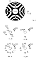
- Figures 5A to 5D show some possible constellations between the shaft hole and the positioning holes.
- the shaft holes 500A to 500D are centrally positioned to the disk.
- the shaft hole and the set of positioning holes are positioned in the rotor disk such that when the rotor disk is set to a rotated position with respect to another similar rotor disk, and the shaft and the positioning pins are penetrated to the respective holes of the two rotor disks, the disks cause a pressing force to the shaft.
- the holes are positioned such that rotationally the disk is somewhat in imbalance.
- the positioning holes 520A to 524A are symmetrically positioned with respect to the shaft hole 500A. That is, if the disk is rotated 90 degrees counter-clockwise around the shaft hole 500A, the positioning hole 520A lands to the previous position (before the rotation) of the positioning hole 522A and the positioning hole 522A lands to the previous position of the hole 524A.
- Figure 5A also shows a fourth positioning hole 526A. In the figure, the positioning hole 526A is shown in the symmetry position but the arrows depict that the hole is, in practice, positioned away from this symmetry position.
- the positioning between the shaft hole 500A and the set of positioning holes 522A to 526A becomes asymmetric.
- a polygon in this case is drawn via the positioning holes, the centre of weight of the polygon is located away from the centre of the shaft hole.
- the displacement of the positioning hole 526A from its symmetry position is small.
- the hole 524A ends up into a position that is partly overlapping with the position of the hole 526A before the rotation.
- the partial overlapping is preferably over 50% of the area of the holes.
- Figure 5B shows an embodiment, where the disk includes an odd number of, that is, three positioning holes.
- the symmetry is defined by the distance and the angle.
- each positioning hole is at the same distance from the shaft hole and the angles between the straight lines via the centre of the shaft hole and the positioning holes are 120 degrees.
- at least one of the positioning holes is at a different distance when compared to the other holes and/or at least one angle between two lines to two neighbouring holes deviates from 120 degrees.
- the positioning hole 526B is positioned away from the symmetry position defined by the other two positioning holes and the shaft hole 500B. Another way to look at Figure 5B is that the positioning hole 526B is positioned into the symmetry position and the two other positioning holes are positioned into asymmetric positions such that the overall positioning of the shaft hole 500B and the three positioning holes is at least partially asymmetric.
- Figure 5C shows an embodiment with 12 positioning holes. Only the hole 526C is positioned away from the symmetry position defined by the 11 other holes and the shaft hole 500C. Considering this example and two similar rotor disks, there is only one rotation angle of the disks where all the holes are fully aligned with each other. When the two disks are put to some other rotated position, at least some of the mutual holes of the disks are only partly overlapping with other. By a “rotated position", it is meant any rotation angle being 360/n, where n is an integer above 1 but less than the number of holes.
- Figure 5D shows a situation where the other positioning holes except 526D are positioned symmetrically with respect to the shaft hole.
- the displacement of the positioning hole 526D from the symmetry position causes that the overall constellation between the shaft hole and the eight positioning holes becomes asymmetric.
- the positioning holes may be combined with the neighbouring positioning holes such that a polygon is formed.
- a centre of weight of the polygon can be determined.
- Figures 6A and 6B illustrate the method of mounting the motor shaft and rotor on each other.
- Figure 6A shows the situation before mounting the shaft on the rotor and 6B after the mounting.
- the shaft holes 610A to 610H are eccentrically positioned.
- the positioning holes for the positioning pins 640, 642 are symmetrically positioned to the disks. Due to the eccentricity of the shaft hole and the symmetrical positioning of the positioning holes to the disk, the mutual positioning of the shaft hole and the positioning holes is asymmetric.
- the shaft holes 610A to 610H are partly in misalignment with each other.
- the odd (first, third, fifth, seventh) disks are rotated 180 degrees with respect to the even (second, fourth, sixth, eighth) disks.
- the disks 600A and 600H are rotated 180 degrees with respect to each other such that the shaft holes 610A and 610H are in misalignment with each other.
- the positioning pins 640, 642 are put into the positioning holes of the disks.
- the positioning holes are symmetrically positioned in the disk and, thus, when the outer edges of the disks are aligned with each other, the positioning holes in different disks are aligned with other and it is possible to insert the positioning pins practically without any force through the positioning holes.
- Each disk may include at least two positioning holes for the positioning pins. If there is an even number of positioning holes, pairs of positioning holes are formed, wherein the holes are substantially opposite to each other on the different sides of the disk centre.
- the head 660 of the shaft 612 may be formed such that there is a slide, which pushes the odd disks downward and even disks upwards.
- Figure 6B shows a situation, where the shaft 612 has been pressed to the shaft holes of the disks 600A to 600H.
- the displacement of the disks can be seen in that the odd disks have moved slightly downward and the even disks have moved slightly upward.
- the outer edges of the rotor disks 600A to 600H are not in alignment with each other.
- the shaft hole in each disk exerts a force to the shaft to fasten it tightly such that the rotation of the shaft with respect to the rotor is prevented.
- Figure 7 shows an embodiment of a method according to the invention.
- the method relates to mounting of a motor shaft on a rotor of an electric motor.
- the rotor disks that are used in the embodiment of Figure 7 are such that the disks include an eccentrically positioned shaft hole for the motor shaft having a circular cross-section.
- the disks include two or more positioning holes for the positioning pins, which in the embodiment of Figure 7 are positioned symmetrically to the disk.
- the shaft hole is eccentrically and the positioning holes are symmetrically positioned with respect to the disk, they are positioned mutually asymmetrically.
- the asymmetry can be tested by rotating the disk around the centre point of the shaft hole at an angle which is "360 degrees divided by the number of the positioning holes", the constellation of the positioning holes around the shaft hole differing from the constellation before the rotation. That is, when two similar disks are put to a rotated position with respect to each other, at least some of the holes are only partly overlapping with the respective holes in the other disk.
- the rotor disks forming the rotor are rotated with respect to the other rotor disks such that the shaft holes in the rotor disks are in misalignment when the positioning holes are aligned to each other.
- the mutual rotation of the disks is 180 degrees.
- the rotation angle may be 90 or 180 degrees, and so on.
- the mutual rotation of the disks may be such that every other disk is rotated.
- a sub-stack of disks may be rotated when compared to a neighbouring sub-stack.
- a sub-stack of five disks may have the same rotation, the next sub-stack of five disks another rotation, and so on.
- the outcome of 702 is that at least in some disks the shaft holes in the stack of disks are not in alignment with the shaft holes in the neighbouring disks when the disks are otherwise aligned with each other.
- the positioning pins are inserted/protruded to the positioning holes.
- the positioning holes are aligned with each other, as the positioning holes are symmetrically positioned to the disks and the disks are aligned with each other such that the positioning holes of the neighbouring disks overlap.
- the motor shaft is pressed to the shaft holes of the disks. As the shaft holes in the disks are not in alignment with each other, significant force may be needed in this step.
- the motor shaft may be pressed through the shaft holes of the disks by using a hydraulic press, for instance.
- the end of the motor shaft may have a bevelling such as to ease the insertion of the shaft to the disks.
- the shaft holes of the rotor disks are aligned to each other but the outer edges of the rotor disks are in misalignment with each other, depending on how the disks were rotated with respect to each other in step 702.
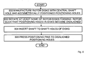
- Figure 8 shows another embodiment of a method.
- rotor disks having a centrally placed shaft hole for a cylindrical shaft, and asymmetrically positioned positioning holes for positioning pins, are manufactured.
- the asymmetry of the mutual positioning of the shaft hole and the positioning holes means in this context that at least one of the positioning holes is in an asymmetric position when compared to the other positioning holes and the shaft hole.
- the rotation can be 180 degrees (360/2), in the case of three positioning holes the rotation can be 120 (360/3) or 240 (2*360/3) degrees, and so on.
- the shaft is inserted to the shaft holes of the disks. As the shaft holes are aligned in this step, no significant force is needed.
- steps 802 and 804 may also be carried out in such an order that the disks are first put onto the shaft and the rotation of the disks with respect to each other is carried out when the shaft is already in the shaft holes of the disks.
- the positioning pins are pressed to the positioning holes that are at least partially misaligned to each other.
- a hydraulic press may be used for this purpose.
- the shaft hole in the rotor disk is arranged eccentrically, that is, the shaft hole is not exactly in the centre of the disk.
- the displacement of the shaft hole from the centre of the disk may be 0.2 to 0.4 mm, for instance.
- the positioning holes are positioned symmetrically to the disk, and thus the mutual positioning of the shaft hole and the positioning holes is asymmetric. The centre of weight of the positioning holes is thus displaced from the centre of weight of the shaft hole.
- the shaft hole is arranged centrally to the rotor disk, and the set of positioning holes is arranged asymmetrically with respect to the centrally arranged shaft hole, whereby the centre of weight of a polygon formed by the positioning holes differs from the centre of the shaft hole.
- the set of positioning holes is arranged asymmetrically with respect to the centrally placed shaft hole, this means that the set of positioning holes is also arranged asymmetrically with respect to the rotor disk.
- asymmetry is meant that at least one positioning hole in the set of positioning holes is arranged asymmetrically with respect to the other holes. That is, if there are two holes, these holes are not arranged symmetrically with respect to the shaft hole. If there are three holes, it may be that two of the holes are symmetrically arranged to the shaft hole but the third hole is not symmetrically arranged with the two other ones. Alternatively, all three holes are asymmetrically arranged, that is there is no symmetry between any of the holes and the shaft hole.
- the number of positioning holes may be any number higher than one.
- the shaft hole is arranged eccentrically, and the set of positioning holes is arranged asymmetrically with respect to the rotor disk.
- the rotor disk is configured to flex when the shaft is projected into the shaft hole or when a positioning pin is inserted into the positioning hole.
- the disk flexes.
- the flexing of the disk may be provided by a flexing element of the disk.
- the asymmetry with respect to the shaft hole of the positioning holes may be defined such that when the disk is rotated around the centre of the shaft hole 360 degrees divided by the number of positioning holes, the position of the shaft hole and/or the position of at least one positioning hole is incongruent with the position of the hole before the rotation. That is, in the case of two holes, for instance, the rotation angle is 180 degrees, with four holes 90 degrees, and so on.
- the rotation angle is 180 degrees, with four holes 90 degrees, and so on.
- the asymmetry may also be defined such that the centre of weight of a planar geometrical shape formed by the positioning holes differs from the centre of the shaft hole.
- the asymmetry can be defined such that the shaft hole and the set of positioning holes are positioned in the rotor disk such that when the rotor disk is set to a rotated position with respect to another similar rotor disk, and the shaft and the positioning pins are penetrated to the respective holes of the two rotor disks, the disks cause a pressing force to the shaft.
- the pressing force is caused by the inner edges of the shaft holes.
- Mutually rotated disks cause essentially opposite pressing forces to the shaft.
- a rotor of the electric motor may comprise a plurality of rotor disks.
- the mounting of the shaft to the stack of rotor disks may be carried out in two alternative ways.
- the positioning pins are mounted first.
- the shaft holes of the rotor disks are in misalignment with each other.
- each disk exerts a force towards the centre of the shaft to mount the shaft tightly to the rotor.
- the shaft is mounted first.
- the positioning holes are somewhat misaligned with each other and the tight mounting of the shaft and rotor is obtained by pressing the positioning pins to misaligned positioning holes.
Landscapes
- Engineering & Computer Science (AREA)
- Power Engineering (AREA)
- Manufacturing & Machinery (AREA)
- Manufacture Of Motors, Generators (AREA)
- Iron Core Of Rotating Electric Machines (AREA)
- Connection Of Motors, Electrical Generators, Mechanical Devices, And The Like (AREA)
- Motor Or Generator Frames (AREA)
Claims (14)
- Rotorscheibe für einen Elektromotor, aufweisend:eine Wellenbohrung (310) zum Aufnehmen einer Welle (312) des Elektromotors;eine Reihe von Positionierungsbohrungen (320, 322, 324, 326) um die Wellenbohrung (310), wobei jede von ihnen konfiguriert ist, einen Positionierungsstift (340, 342, 344, 346) aufzunehmen, dadurch gekennzeichnet, dass die Wellenbohrung (500A) und die Reihe von Positionierungsbohrungen (520A, 522A, 524A, 526A) in Bezug aufeinander asymmetrisch angeordnet sind, wobei die Wellenbohrung (310) und die Reihe von Positionierungsbohrungen (320, 322, 324, 326) in der Rotorscheibe (300) derart positioniert sind, dass, wenn die Rotorscheibe (300) in Bezug auf eine andere ähnliche Rotorscheibe (302) in eine gedrehte Position gestellt wird und die Welle (312) und die Positionierungsstifte (340, 342, 344, 346) in die entsprechenden Bohrungen der zwei Rotorscheiben (300, 302) eingedrungen sind, die Scheiben (300, 302) eine Presskraft auf die Welle (312) bewirken.
- Rotorscheibe nach Anspruch 1, dadurch gekennzeichnet , dass die Reihe von Positionierungsbohrungen (520A, 522A, 524A, 526A) eine ebene-geometrische Form ausbildet, deren Schwerpunkt sich vom Mittelpunkt der Wellenbohrung (500A) unterscheidet.
- Rotorscheibe nach Anspruch 2, dadurch gekennzeichnet, dass sich der Schwerpunkt eines über die Positionierungsbohrungen (520A, 522A, 524A, 526A) gezeichneten Polygons vom Mittelpunkt der Wellenbohrung (500A) abweicht.
- Rotorscheibe nach Anspruch 1, dadurch gekennzeichnet, dass
die Wellenbohrung (610A) exzentrisch zur Rotorscheibe (600A) angeordnet ist; und
die Reihe von Positionierungsbohrungen symmetrisch in der Rotorscheibe angeordnet ist. - Rotorscheibe nach Anspruch 1, dadurch gekennzeichnet, dass
die Wellenbohrung (500A) zentral zur Rotorscheibe angeordnet ist und
die Reihe von Positionierungsbohrungen (520A, 522A, 524A, 526A) in Bezug auf die zentral angeordnete Wellenbohrung (500A) asymmetrisch angeordnet ist. - Rotorscheibe nach Anspruch 1, dadurch gekennzeichnet, dass die Reihe von Positionierungsbohrungen (320, 322, 324, 326) und die Wellenbohrung (310) in Bezug aufeinander derart angeordnet sind, dass, falls zwei ähnliche Rotorscheiben (300, 302) aufeinander ausgerichtet sind und eine der Scheiben (300) 360 Grad, dividiert durch die Anzahl von Positionierungsbohrungen, gedreht wird, zumindest eine der Wellenbohrung und Positionierungsbohrungen nur teilweise die entsprechende Bohrung in der anderen Rotorscheibe überlappt.
- Rotorscheibe nach Anspruch 1, dadurch gekennzeichnet, dass die in Bezug aufeinander gedrehten Scheiben (300, 302) konfiguriert sind, wesentlich entgegengesetzte Presskräfte auf die Welle auszuüben.
- Rotorscheibe nach Anspruch 1, dadurch gekennzeichnet, dass die Rotorscheibe (400) konfiguriert ist, sich zu beugen, wenn die Welle in die Wellenbohrung (410) eingeführt wird oder wenn ein Positionierungsstift in die Positionierungsbohrung eingeführt wird.
- Rotorscheibe nach Anspruch 1, dadurch gekennzeichnet, dass die Wellenbohrung (410) ein Kreis ist, um eine Welle mit einem kreisförmigen Querschnitt aufnimmt.
- Elektromotor, dadurch gekennzeichnet, dass der Elektromotor:eine Vielzahl von Rotorscheiben (600A bis 600H) nach einem der vorhergehenden Ansprüche aufweist, wobei zumindest einige der Rotorscheiben in Bezug auf die anderen Rotorscheiben in eine gedrehte Position gestellt werden, wenn die Welle (612) und die Positionierungsstifte (640, 642) derart am Elektromotor montiert sind, dass die Rotorscheiben (600A bis 600H) eine Presskraft auf die Welle (612) bewirken.
- Elektromotor nach Anspruch 10, dadurch gekennzeichnet, dass der Elektromotor:eine Welle (612) mit einem kreisförmigen Querschnitt aufweist, wobei der Durchmesser des Querschnitts der Welle kleiner als die Durchmesser der Wellenbohrungen (610A bis 610H) in der Vielzahl von Rotorscheiben bei derselben Temperatur ist.
- Verfahren zur Montierung einer Motorwelle an einem Rotor eines Elektromotors, dadurch gekennzeichnet, dass
eine Vielzahl von Rotorscheiben mit einer Wellenbohrung zum Aufnehmen der Welle des Elektromotors und einer Reihe von Positionierungsbohrungen vorgesehen wird (700, 800), wobei jede von ihnen angeordnet ist, einen Positionierungsstift aufzunehmen, wobei die Wellenbohrung (500A) und die Reihe von Positionierungsbohrungen (520A, 522A, 524A, 526A) in Bezug aufeinander asymmetrisch angeordnet sind, wobei die Wellenbohrung und die Reihe von Positionierungsbohrungen in der Rotorscheibe derart positioniert sind, dass es nur eine gegenseitige Drehposition gibt, wenn die Bohrungen der Scheiben einander vollständig überlappen;
zumindest einige der Rotorscheiben in Bezug aufeinander derart gedreht werden (702, 802), dass in der Vielzahl von Rotorscheiben eine der Wellenbohrungen und die Reihe von Positionierungsbohrungen einander überlappen und eine der Wellenbohrungen und die Reihe von Positionierungsbohrungen einander nur teilweise überlappen;
zuerst die Motorwelle in die Wellenbohrung oder die Positionierungsstifte in die Positionierungsbohrungen eingeführt wird/werden (704, 804), je nachdem, welche der Bohrungen in den Scheiben einander überlappen, und
zweitens die Motorwelle in die Wellenbohrung oder die Positionierungsstifte in die Positionierungsbohrungen eingeführt wird/werden (706, 806), je nachdem, welche der Bohrungen in den Scheiben einander nur teilweise überlappen. - Verfahren nach Anspruch 12, dadurch gekennzeichnet, dass
eine Vielzahl von Rotorscheiben mit einer exzentrisch positionierten Wellenbohrung vorgesehen wird (700) und eine Reihe von symmetrisch auf der Rotorscheibe angeordneten Positionierungsbohrungen angeordnet wird;
zumindest einige der Rotorscheiben in Bezug aufeinander derart gedreht werden (702), dass die Wellenbohrungen einander nur teilweise überlappen und die symmetrisch positionierten Positionierungsbohrungen einander überlappen;
die Positionierungsstifte in die Positionierungsbohrungen der Vielzahl von Rotorscheiben eingeführt werden (704); und
die Motorwelle in die Wellenbohrungen der Rotorscheiben gedrückt wird (706). - Verfahren nach Anspruch 12, dadurch gekennzeichnet, dass
eine Vielzahl von Rotorscheiben mit einer zentral positionierten Wellenbohrung und einer Reihe von zumindest teilweise asymmetrisch in Bezug auf die zentral angeordnete Wellenbohrung angeordneten Positionierungsbohrungen vorgesehen werden (800);
zumindest einige der Rotorscheiben in Bezug aufeinander derart gedreht werden (802), dass die Positionierungsbohrungen einander nur teilweise überlappen; und
die Motorwelle in die Wellenbohrungen der Vielzahl von Rotorscheiben eingeführt wird (804); und
die Positionierungsstifte in die Positionierungsbohrungen der Rotorscheiben gedrückt werden (806), wenn die Motorwelle in die Wellenbohrungen der Rotorscheiben eingeführt worden ist.
Priority Applications (10)
| Application Number | Priority Date | Filing Date | Title |
|---|---|---|---|
| ES09176731T ES2422754T5 (es) | 2009-11-23 | 2009-11-23 | Disco rotor y método de montaje |
| PL09176731T PL2325980T5 (pl) | 2009-11-23 | 2009-11-23 | Tarcza wirnikowa i sposób montażu |
| PT91767319T PT2325980E (pt) | 2009-11-23 | 2009-11-23 | Disco de rotor e método de montagem |
| EP09176731.9A EP2325980B2 (de) | 2009-11-23 | 2009-11-23 | Rotorscheibe und Montageverfahren |
| KR1020127016354A KR101381213B1 (ko) | 2009-11-23 | 2010-11-23 | 회전자 디스크 및 조립 방법 |
| CN201080052837.0A CN102668331B (zh) | 2009-11-23 | 2010-11-23 | 转子盘及装配方法 |
| JP2012539377A JP5635618B2 (ja) | 2009-11-23 | 2010-11-23 | ロータ・ディスク及び組み立て方法 |
| PCT/FI2010/050948 WO2011061409A1 (en) | 2009-11-23 | 2010-11-23 | Rotor disk and assembly method |
| BR112012012183-9A BR112012012183B1 (pt) | 2009-11-23 | 2010-11-23 | Disco do rotor e metodo de montagem |
| US13/477,752 US8901799B2 (en) | 2009-11-23 | 2012-05-22 | Rotor disk and assembly method |
Applications Claiming Priority (1)
| Application Number | Priority Date | Filing Date | Title |
|---|---|---|---|
| EP09176731.9A EP2325980B2 (de) | 2009-11-23 | 2009-11-23 | Rotorscheibe und Montageverfahren |
Publications (3)
| Publication Number | Publication Date |
|---|---|
| EP2325980A1 EP2325980A1 (de) | 2011-05-25 |
| EP2325980B1 true EP2325980B1 (de) | 2013-06-19 |
| EP2325980B2 EP2325980B2 (de) | 2018-11-07 |
Family
ID=43125498
Family Applications (1)
| Application Number | Title | Priority Date | Filing Date |
|---|---|---|---|
| EP09176731.9A Active EP2325980B2 (de) | 2009-11-23 | 2009-11-23 | Rotorscheibe und Montageverfahren |
Country Status (10)
| Country | Link |
|---|---|
| US (1) | US8901799B2 (de) |
| EP (1) | EP2325980B2 (de) |
| JP (1) | JP5635618B2 (de) |
| KR (1) | KR101381213B1 (de) |
| CN (1) | CN102668331B (de) |
| BR (1) | BR112012012183B1 (de) |
| ES (1) | ES2422754T5 (de) |
| PL (1) | PL2325980T5 (de) |
| PT (1) | PT2325980E (de) |
| WO (1) | WO2011061409A1 (de) |
Families Citing this family (13)
| Publication number | Priority date | Publication date | Assignee | Title |
|---|---|---|---|---|
| WO2013013778A2 (de) * | 2011-07-22 | 2013-01-31 | Ebm-Papst St. Georgen Gmbh & Co. Kg | Innenläufermotor |
| JP5840006B2 (ja) * | 2012-01-24 | 2016-01-06 | 株式会社三井ハイテック | 回転子鉄心のシャフト固定方法 |
| JP5843692B2 (ja) * | 2012-05-15 | 2016-01-13 | 三菱電機株式会社 | 回転電機の回転子の積層鉄心の製造方法 |
| ES2612255T3 (es) * | 2012-12-14 | 2017-05-16 | Abb Schweiz Ag | Rotor para una máquina eléctrica, una máquina eléctrica y un método para fabricar una máquina eléctrica |
| DE102013206045A1 (de) * | 2013-04-05 | 2014-10-09 | Ksb Aktiengesellschaft | Verfahren zur Herstellung eines Rotors und Rotor |
| EP2961039B1 (de) * | 2014-06-23 | 2019-10-02 | Siemens Aktiengesellschaft | Mechanisch stabilisierter Rotor für einen Reluktanzmotor |
| JP6476385B2 (ja) * | 2015-05-25 | 2019-03-06 | 多摩川精機株式会社 | レゾルバロータ位置決め構造及び方法 |
| CN106612024A (zh) * | 2015-10-27 | 2017-05-03 | Abb技术有限公司 | 转子以及用于制造转子的方法 |
| JP6593125B2 (ja) * | 2015-11-25 | 2019-10-23 | 株式会社デンソー | ワイパユニット |
| CN109980806A (zh) * | 2017-12-28 | 2019-07-05 | 丹佛斯(天津)有限公司 | 电机转子和电机 |
| JP7228182B2 (ja) * | 2018-12-17 | 2023-02-24 | Kyb株式会社 | ロータ及びロータの製造方法 |
| KR102471079B1 (ko) * | 2020-12-01 | 2022-11-25 | 주식회사 에스 씨디 | 모터용 로터 |
| JP7512955B2 (ja) * | 2021-06-02 | 2024-07-09 | トヨタ自動車株式会社 | ステータとその製造方法 |
Family Cites Families (28)
| Publication number | Priority date | Publication date | Assignee | Title |
|---|---|---|---|---|
| US3141233A (en) † | 1959-01-13 | 1964-07-21 | Alliance Mfg Co | Rotor and shaft assembly method |
| DE2145132A1 (de) † | 1971-09-09 | 1973-03-22 | Black & Decker Mfg Co | Anker fuer einen elektromotor |
| DE2349359A1 (de) † | 1973-10-02 | 1975-04-10 | Licentia Gmbh | An einer glatten welle befestigtes laeuferblechpaket eines kleinmotors |
| US4361953A (en) * | 1978-10-31 | 1982-12-07 | Emerson Electric Co. | Method of securing end shields to the stator assembly of a dynamoelectric machine |
| JPH01157565U (de) * | 1988-04-12 | 1989-10-31 | ||
| JP2701048B2 (ja) | 1988-07-22 | 1998-01-21 | 黒田精工株式会社 | 回転子とその製造方法 |
| JPH054743U (ja) † | 1991-07-05 | 1993-01-22 | 株式会社東芝 | 永久磁石式回転子 |
| JPH05284680A (ja) † | 1992-04-01 | 1993-10-29 | Toshiba Corp | 永久磁石式回転子 |
| JP3501161B2 (ja) † | 1992-07-08 | 2004-03-02 | 松下電器産業株式会社 | 誘導電動機 |
| JP2583279Y2 (ja) * | 1992-11-20 | 1998-10-22 | 株式会社安川電機 | 回転電機の回転子 |
| JPH07298527A (ja) † | 1994-04-27 | 1995-11-10 | Asmo Co Ltd | 積層コアを有する回転電機のロータ構造 |
| JPH08163834A (ja) | 1994-12-02 | 1996-06-21 | Yaskawa Electric Corp | 積層鉄心の固定方法 |
| BR9705579A (pt) † | 1997-09-26 | 1999-05-11 | Brasil Compressores Sa | Rotor de motor elétrico e método de produção de rotor de motor elétrico |
| US6177750B1 (en) * | 1998-07-14 | 2001-01-23 | Reliance Electric Technologies, Llc | Rotating assembly construction for high speed induction motor |
| KR20000009230A (ko) * | 1998-07-22 | 2000-02-15 | 윤종용 | 브리시리스 직류 전동기 |
| US6177749B1 (en) * | 1998-11-12 | 2001-01-23 | Emerson Electric Co. | Polygonal shaft hole rotor |
| DE19962821A1 (de) † | 1999-12-23 | 2001-06-28 | Mannesmann Vdo Ag | Rotor für eine Gleichstrommaschine sowie Verfahren zu seiner Herstellung |
| JP2004023848A (ja) † | 2002-06-13 | 2004-01-22 | Asmo Co Ltd | モータのロータコア構造及びその製造方法 |
| US7157827B2 (en) * | 2004-09-21 | 2007-01-02 | A. O. Smith Corporation | Spoke permanent magnet rotor |
| JP4010319B2 (ja) | 2005-02-09 | 2007-11-21 | ダイキン工業株式会社 | コア及び回転子並びにモータ及び圧縮機 |
| CN101116235A (zh) * | 2005-02-09 | 2008-01-30 | 大金工业株式会社 | 铁芯及转子和电动机及压缩机 |
| US7687949B2 (en) † | 2005-05-12 | 2010-03-30 | Lg Electronics Inc. | Rotor of synchronous reluctance motor |
| JPWO2006132171A1 (ja) * | 2005-06-07 | 2009-01-08 | 株式会社ミツバ | 回転電機のアーマチュアおよびその製造方法 |
| JP2007181270A (ja) † | 2005-12-27 | 2007-07-12 | Toyota Motor Corp | 回転電機のロータ |
| JP5000262B2 (ja) † | 2006-10-23 | 2012-08-15 | 三菱電機株式会社 | 回転電機用回転子 |
| DE102008020779A1 (de) † | 2008-04-25 | 2009-11-05 | Siemens Aktiengesellschaft | Rotor mit einzelnen Teilsegmenten und elektrische Maschine |
| DE102008020778A1 (de) † | 2008-04-25 | 2009-11-05 | Siemens Aktiengesellschaft | Rotor für eine Synchronmaschine, Herstellungsverfahren für einen derartigen Rotor sowie Synchronmaschine mit einem derartigen Rotor |
| GB2468718A (en) † | 2009-03-20 | 2010-09-22 | Control Tech Dynamics Ltd | Securing permanent magnets to a laminated rotor |
-
2009
- 2009-11-23 EP EP09176731.9A patent/EP2325980B2/de active Active
- 2009-11-23 PT PT91767319T patent/PT2325980E/pt unknown
- 2009-11-23 PL PL09176731T patent/PL2325980T5/pl unknown
- 2009-11-23 ES ES09176731T patent/ES2422754T5/es active Active
-
2010
- 2010-11-23 CN CN201080052837.0A patent/CN102668331B/zh active Active
- 2010-11-23 BR BR112012012183-9A patent/BR112012012183B1/pt active IP Right Grant
- 2010-11-23 WO PCT/FI2010/050948 patent/WO2011061409A1/en not_active Ceased
- 2010-11-23 JP JP2012539377A patent/JP5635618B2/ja active Active
- 2010-11-23 KR KR1020127016354A patent/KR101381213B1/ko active Active
-
2012
- 2012-05-22 US US13/477,752 patent/US8901799B2/en active Active
Also Published As
| Publication number | Publication date |
|---|---|
| KR20120096542A (ko) | 2012-08-30 |
| JP2013511947A (ja) | 2013-04-04 |
| PT2325980E (pt) | 2013-08-05 |
| JP5635618B2 (ja) | 2014-12-03 |
| ES2422754T5 (es) | 2019-04-17 |
| PL2325980T5 (pl) | 2020-10-05 |
| US20120293038A1 (en) | 2012-11-22 |
| CN102668331A (zh) | 2012-09-12 |
| KR101381213B1 (ko) | 2014-04-07 |
| ES2422754T3 (es) | 2013-09-13 |
| CN102668331B (zh) | 2015-04-08 |
| WO2011061409A1 (en) | 2011-05-26 |
| BR112012012183A2 (pt) | 2016-04-12 |
| EP2325980A1 (de) | 2011-05-25 |
| BR112012012183A8 (pt) | 2017-12-19 |
| BR112012012183B1 (pt) | 2020-11-24 |
| PL2325980T3 (pl) | 2013-09-30 |
| US8901799B2 (en) | 2014-12-02 |
| EP2325980B2 (de) | 2018-11-07 |
Similar Documents
| Publication | Publication Date | Title |
|---|---|---|
| EP2325980B1 (de) | Rotorscheibe und Montageverfahren | |
| US8766505B2 (en) | Rotating electrical machine and method for manufacturing rotating electrical machine | |
| CN102484404B (zh) | 电动装置转子及其制造方法 | |
| JP6482240B2 (ja) | モータ用ロータ及びモータ | |
| JP3687749B2 (ja) | スキュー形状可変型積層鉄心及びその製造方法 | |
| US9136746B2 (en) | Stator for electric rotating machine and method of manufacturing the same | |
| US20130187505A1 (en) | Rotor having dividable core for electric motor and production method thereof | |
| CN105122596B (zh) | 具有通过弯曲载体保持的单区段的单区段转子和制造方法 | |
| US20140041207A1 (en) | Method for producing a motor rotor | |
| JPWO2019198708A1 (ja) | 回転電機のステータ、回転電機、および、回転電機のステータの製造方法 | |
| JP7321099B2 (ja) | 刻み目が付けられたロータシャフトを備えている電気機械と、そのような機械の製造方法 | |
| US20230028465A1 (en) | Stator for a rotating electrical machine | |
| CN106612024A (zh) | 转子以及用于制造转子的方法 | |
| CN114552808A (zh) | 定子铁芯、定子及电机 | |
| KR20130017232A (ko) | 모터의 적층 로터 코어 | |
| KR101471136B1 (ko) | 모터 어셈블리의 냉각 구조 | |
| JP7807443B2 (ja) | モータ | |
| KR101982646B1 (ko) | 모터의 적층 로터 코어 | |
| EP2676356A1 (de) | System und verfahren zum positionieren und fixieren von objekten in relation zueinander | |
| CN206790309U (zh) | 自动转子铁芯组装装置及具备该装置的马达制造设备 | |
| CN115694097A (zh) | 用于制造转子片组的方法 | |
| KR20250101019A (ko) | 전기 모터의 회전자 조립체 | |
| CN121566818A (zh) | 一种电机转子磁石固定结构及固定方法 | |
| KR20030011184A (ko) | 플럭스 배리어 타입 동기 리럭턴스 모터의 로터 및 그제조방법 | |
| JP2018001212A (ja) | 熱交換器の製造装置 |
Legal Events
| Date | Code | Title | Description |
|---|---|---|---|
| PUAI | Public reference made under article 153(3) epc to a published international application that has entered the european phase |
Free format text: ORIGINAL CODE: 0009012 |
|
| AK | Designated contracting states |
Kind code of ref document: A1 Designated state(s): AT BE BG CH CY CZ DE DK EE ES FI FR GB GR HR HU IE IS IT LI LT LU LV MC MK MT NL NO PL PT RO SE SI SK SM TR |
|
| AX | Request for extension of the european patent |
Extension state: AL BA RS |
|
| 17P | Request for examination filed |
Effective date: 20110928 |
|
| 17Q | First examination report despatched |
Effective date: 20121128 |
|
| GRAP | Despatch of communication of intention to grant a patent |
Free format text: ORIGINAL CODE: EPIDOSNIGR1 |
|
| GRAS | Grant fee paid |
Free format text: ORIGINAL CODE: EPIDOSNIGR3 |
|
| GRAA | (expected) grant |
Free format text: ORIGINAL CODE: 0009210 |
|
| AK | Designated contracting states |
Kind code of ref document: B1 Designated state(s): AT BE BG CH CY CZ DE DK EE ES FI FR GB GR HR HU IE IS IT LI LT LU LV MC MK MT NL NO PL PT RO SE SI SK SM TR |
|
| REG | Reference to a national code |
Ref country code: GB Ref legal event code: FG4D |
|
| REG | Reference to a national code |
Ref country code: CH Ref legal event code: EP |
|
| REG | Reference to a national code |
Ref country code: AT Ref legal event code: REF Ref document number: 618105 Country of ref document: AT Kind code of ref document: T Effective date: 20130715 |
|
| REG | Reference to a national code |
Ref country code: IE Ref legal event code: FG4D |
|
| REG | Reference to a national code |
Ref country code: PT Ref legal event code: SC4A Free format text: AVAILABILITY OF NATIONAL TRANSLATION Effective date: 20130730 |
|
| REG | Reference to a national code |
Ref country code: DE Ref legal event code: R096 Ref document number: 602009016492 Country of ref document: DE Effective date: 20130814 |
|
| REG | Reference to a national code |
Ref country code: ES Ref legal event code: FG2A Ref document number: 2422754 Country of ref document: ES Kind code of ref document: T3 Effective date: 20130913 |
|
| REG | Reference to a national code |
Ref country code: PL Ref legal event code: T3 |
|
| PG25 | Lapsed in a contracting state [announced via postgrant information from national office to epo] |
Ref country code: LT Free format text: LAPSE BECAUSE OF FAILURE TO SUBMIT A TRANSLATION OF THE DESCRIPTION OR TO PAY THE FEE WITHIN THE PRESCRIBED TIME-LIMIT Effective date: 20130619 Ref country code: SI Free format text: LAPSE BECAUSE OF FAILURE TO SUBMIT A TRANSLATION OF THE DESCRIPTION OR TO PAY THE FEE WITHIN THE PRESCRIBED TIME-LIMIT Effective date: 20130619 Ref country code: NO Free format text: LAPSE BECAUSE OF FAILURE TO SUBMIT A TRANSLATION OF THE DESCRIPTION OR TO PAY THE FEE WITHIN THE PRESCRIBED TIME-LIMIT Effective date: 20130919 Ref country code: SE Free format text: LAPSE BECAUSE OF FAILURE TO SUBMIT A TRANSLATION OF THE DESCRIPTION OR TO PAY THE FEE WITHIN THE PRESCRIBED TIME-LIMIT Effective date: 20130619 Ref country code: FI Free format text: LAPSE BECAUSE OF FAILURE TO SUBMIT A TRANSLATION OF THE DESCRIPTION OR TO PAY THE FEE WITHIN THE PRESCRIBED TIME-LIMIT Effective date: 20130619 Ref country code: GR Free format text: LAPSE BECAUSE OF FAILURE TO SUBMIT A TRANSLATION OF THE DESCRIPTION OR TO PAY THE FEE WITHIN THE PRESCRIBED TIME-LIMIT Effective date: 20130920 |
|
| REG | Reference to a national code |
Ref country code: LT Ref legal event code: MG4D |
|
| PG25 | Lapsed in a contracting state [announced via postgrant information from national office to epo] |
Ref country code: BG Free format text: LAPSE BECAUSE OF FAILURE TO SUBMIT A TRANSLATION OF THE DESCRIPTION OR TO PAY THE FEE WITHIN THE PRESCRIBED TIME-LIMIT Effective date: 20130919 Ref country code: HR Free format text: LAPSE BECAUSE OF FAILURE TO SUBMIT A TRANSLATION OF THE DESCRIPTION OR TO PAY THE FEE WITHIN THE PRESCRIBED TIME-LIMIT Effective date: 20130619 |
|
| REG | Reference to a national code |
Ref country code: NL Ref legal event code: VDEP Effective date: 20130619 |
|
| PG25 | Lapsed in a contracting state [announced via postgrant information from national office to epo] |
Ref country code: LV Free format text: LAPSE BECAUSE OF FAILURE TO SUBMIT A TRANSLATION OF THE DESCRIPTION OR TO PAY THE FEE WITHIN THE PRESCRIBED TIME-LIMIT Effective date: 20130619 |
|
| PG25 | Lapsed in a contracting state [announced via postgrant information from national office to epo] |
Ref country code: SK Free format text: LAPSE BECAUSE OF FAILURE TO SUBMIT A TRANSLATION OF THE DESCRIPTION OR TO PAY THE FEE WITHIN THE PRESCRIBED TIME-LIMIT Effective date: 20130619 Ref country code: CY Free format text: LAPSE BECAUSE OF FAILURE TO SUBMIT A TRANSLATION OF THE DESCRIPTION OR TO PAY THE FEE WITHIN THE PRESCRIBED TIME-LIMIT Effective date: 20130717 Ref country code: IS Free format text: LAPSE BECAUSE OF FAILURE TO SUBMIT A TRANSLATION OF THE DESCRIPTION OR TO PAY THE FEE WITHIN THE PRESCRIBED TIME-LIMIT Effective date: 20131019 Ref country code: EE Free format text: LAPSE BECAUSE OF FAILURE TO SUBMIT A TRANSLATION OF THE DESCRIPTION OR TO PAY THE FEE WITHIN THE PRESCRIBED TIME-LIMIT Effective date: 20130619 |
|
| PG25 | Lapsed in a contracting state [announced via postgrant information from national office to epo] |
Ref country code: RO Free format text: LAPSE BECAUSE OF FAILURE TO SUBMIT A TRANSLATION OF THE DESCRIPTION OR TO PAY THE FEE WITHIN THE PRESCRIBED TIME-LIMIT Effective date: 20130619 Ref country code: NL Free format text: LAPSE BECAUSE OF FAILURE TO SUBMIT A TRANSLATION OF THE DESCRIPTION OR TO PAY THE FEE WITHIN THE PRESCRIBED TIME-LIMIT Effective date: 20130619 |
|
| REG | Reference to a national code |
Ref country code: DE Ref legal event code: R026 Ref document number: 602009016492 Country of ref document: DE |
|
| PG25 | Lapsed in a contracting state [announced via postgrant information from national office to epo] |
Ref country code: CY Free format text: LAPSE BECAUSE OF FAILURE TO SUBMIT A TRANSLATION OF THE DESCRIPTION OR TO PAY THE FEE WITHIN THE PRESCRIBED TIME-LIMIT Effective date: 20130619 |
|
| PLBE | No opposition filed within time limit |
Free format text: ORIGINAL CODE: 0009261 |
|
| PG25 | Lapsed in a contracting state [announced via postgrant information from national office to epo] |
Ref country code: DK Free format text: LAPSE BECAUSE OF FAILURE TO SUBMIT A TRANSLATION OF THE DESCRIPTION OR TO PAY THE FEE WITHIN THE PRESCRIBED TIME-LIMIT Effective date: 20130619 |
|
| PLAA | Information modified related to event that no opposition was filed |
Free format text: ORIGINAL CODE: 0009299DELT |
|
| PLBE | No opposition filed within time limit |
Free format text: ORIGINAL CODE: 0009261 |
|
| 26N | No opposition filed |
Effective date: 20140320 |
|
| R26N | No opposition filed (corrected) |
Effective date: 20140320 |
|
| RAP2 | Party data changed (patent owner data changed or rights of a patent transferred) |
Owner name: ABB TECHNOLOGY AG |
|
| REG | Reference to a national code |
Ref country code: DE Ref legal event code: R097 Ref document number: 602009016492 Country of ref document: DE Effective date: 20140320 |
|
| REG | Reference to a national code |
Ref country code: CH Ref legal event code: PL |
|
| PG25 | Lapsed in a contracting state [announced via postgrant information from national office to epo] |
Ref country code: CH Free format text: LAPSE BECAUSE OF NON-PAYMENT OF DUE FEES Effective date: 20131130 Ref country code: LI Free format text: LAPSE BECAUSE OF NON-PAYMENT OF DUE FEES Effective date: 20131130 Ref country code: MC Free format text: LAPSE BECAUSE OF FAILURE TO SUBMIT A TRANSLATION OF THE DESCRIPTION OR TO PAY THE FEE WITHIN THE PRESCRIBED TIME-LIMIT Effective date: 20130619 |
|
| REG | Reference to a national code |
Ref country code: IE Ref legal event code: MM4A |
|
| REG | Reference to a national code |
Ref country code: PT Ref legal event code: PC4A Owner name: ABB TECHNOLOGY AG, CH Effective date: 20140930 |
|
| PG25 | Lapsed in a contracting state [announced via postgrant information from national office to epo] |
Ref country code: IE Free format text: LAPSE BECAUSE OF NON-PAYMENT OF DUE FEES Effective date: 20131123 |
|
| REG | Reference to a national code |
Ref country code: DE Ref legal event code: R081 Ref document number: 602009016492 Country of ref document: DE Owner name: ABB TECHNOLOGY AG, CH Free format text: FORMER OWNER: ABB OY, HELSINKI, FI Effective date: 20141015 Ref country code: DE Ref legal event code: R081 Ref document number: 602009016492 Country of ref document: DE Owner name: ABB SCHWEIZ AG, CH Free format text: FORMER OWNER: ABB OY, HELSINKI, FI Effective date: 20141015 |
|
| REG | Reference to a national code |
Ref country code: GB Ref legal event code: 732E Free format text: REGISTERED BETWEEN 20141030 AND 20141105 |
|
| REG | Reference to a national code |
Ref country code: AT Ref legal event code: PC Ref document number: 618105 Country of ref document: AT Kind code of ref document: T Owner name: ABB TECHNOLOGY AG, CH Effective date: 20141029 |
|
| PLAA | Information modified related to event that no opposition was filed |
Free format text: ORIGINAL CODE: 0009299DELT |
|
| PLBI | Opposition filed |
Free format text: ORIGINAL CODE: 0009260 |
|
| PLAX | Notice of opposition and request to file observation + time limit sent |
Free format text: ORIGINAL CODE: EPIDOSNOBS2 |
|
| PG25 | Lapsed in a contracting state [announced via postgrant information from national office to epo] |
Ref country code: SM Free format text: LAPSE BECAUSE OF FAILURE TO SUBMIT A TRANSLATION OF THE DESCRIPTION OR TO PAY THE FEE WITHIN THE PRESCRIBED TIME-LIMIT Effective date: 20130619 |
|
| PLAF | Information modified related to communication of a notice of opposition and request to file observations + time limit |
Free format text: ORIGINAL CODE: EPIDOSCOBS2 |
|
| 26 | Opposition filed |
Opponent name: KSB AKTIENGESELLSCHAFT Effective date: 20140319 |
|
| D26N | No opposition filed (deleted) | ||
| PG25 | Lapsed in a contracting state [announced via postgrant information from national office to epo] |
Ref country code: TR Free format text: LAPSE BECAUSE OF FAILURE TO SUBMIT A TRANSLATION OF THE DESCRIPTION OR TO PAY THE FEE WITHIN THE PRESCRIBED TIME-LIMIT Effective date: 20130619 |
|
| PG25 | Lapsed in a contracting state [announced via postgrant information from national office to epo] |
Ref country code: LU Free format text: LAPSE BECAUSE OF NON-PAYMENT OF DUE FEES Effective date: 20131123 Ref country code: MK Free format text: LAPSE BECAUSE OF FAILURE TO SUBMIT A TRANSLATION OF THE DESCRIPTION OR TO PAY THE FEE WITHIN THE PRESCRIBED TIME-LIMIT Effective date: 20130619 Ref country code: HU Free format text: LAPSE BECAUSE OF FAILURE TO SUBMIT A TRANSLATION OF THE DESCRIPTION OR TO PAY THE FEE WITHIN THE PRESCRIBED TIME-LIMIT; INVALID AB INITIO Effective date: 20091123 |
|
| PG25 | Lapsed in a contracting state [announced via postgrant information from national office to epo] |
Ref country code: MT Free format text: LAPSE BECAUSE OF FAILURE TO SUBMIT A TRANSLATION OF THE DESCRIPTION OR TO PAY THE FEE WITHIN THE PRESCRIBED TIME-LIMIT Effective date: 20130619 |
|
| PLBB | Reply of patent proprietor to notice(s) of opposition received |
Free format text: ORIGINAL CODE: EPIDOSNOBS3 |
|
| REG | Reference to a national code |
Ref country code: FR Ref legal event code: PLFP Year of fee payment: 7 |
|
| REG | Reference to a national code |
Ref country code: FR Ref legal event code: PLFP Year of fee payment: 8 |
|
| REG | Reference to a national code |
Ref country code: DE Ref legal event code: R082 Ref document number: 602009016492 Country of ref document: DE Representative=s name: DENNEMEYER & ASSOCIATES S.A., LU Ref country code: DE Ref legal event code: R081 Ref document number: 602009016492 Country of ref document: DE Owner name: ABB SCHWEIZ AG, CH Free format text: FORMER OWNER: ABB TECHNOLOGY AG, ZUERICH, CH |
|
| RAP2 | Party data changed (patent owner data changed or rights of a patent transferred) |
Owner name: ABB SCHWEIZ AG |
|
| REG | Reference to a national code |
Ref country code: FR Ref legal event code: PLFP Year of fee payment: 9 |
|
| REG | Reference to a national code |
Ref country code: BE Ref legal event code: PD Owner name: ABB SCHWEIZ AG; CH Free format text: DETAILS ASSIGNMENT: CHANGE OF OWNER(S), CESSION; FORMER OWNER NAME: ABB TECHNOLOGY AG Effective date: 20180112 Ref country code: BE Ref legal event code: PD Owner name: ABB TECHNOLOGY AG; CH Free format text: DETAILS ASSIGNMENT: CHANGE OF OWNER(S), AUTRE, CESSION OEB; FORMER OWNER NAME: ABB OY Effective date: 20141013 |
|
| REG | Reference to a national code |
Ref country code: GB Ref legal event code: 732E Free format text: REGISTERED BETWEEN 20180426 AND 20180502 |
|
| REG | Reference to a national code |
Ref country code: AT Ref legal event code: PC Ref document number: 618105 Country of ref document: AT Kind code of ref document: T Owner name: ABB SCHWEIZ AG, CH Effective date: 20180507 |
|
| PUAH | Patent maintained in amended form |
Free format text: ORIGINAL CODE: 0009272 |
|
| STAA | Information on the status of an ep patent application or granted ep patent |
Free format text: STATUS: PATENT MAINTAINED AS AMENDED |
|
| 27A | Patent maintained in amended form |
Effective date: 20181107 |
|
| AK | Designated contracting states |
Kind code of ref document: B2 Designated state(s): AT BE BG CH CY CZ DE DK EE ES FI FR GB GR HR HU IE IS IT LI LT LU LV MC MK MT NL NO PL PT RO SE SI SK SM TR |
|
| REG | Reference to a national code |
Ref country code: DE Ref legal event code: R102 Ref document number: 602009016492 Country of ref document: DE |
|
| REG | Reference to a national code |
Ref country code: ES Ref legal event code: DC2A Ref document number: 2422754 Country of ref document: ES Kind code of ref document: T5 Effective date: 20190417 |
|
| REG | Reference to a national code |
Ref country code: AT Ref legal event code: UEP Ref document number: 618105 Country of ref document: AT Kind code of ref document: T Effective date: 20181107 |
|
| REG | Reference to a national code |
Ref country code: DE Ref legal event code: R082 Ref document number: 602009016492 Country of ref document: DE Representative=s name: DENNEMEYER & ASSOCIATES RECHTSANWALTSGESELLSCH, DE |
|
| PGFP | Annual fee paid to national office [announced via postgrant information from national office to epo] |
Ref country code: PT Payment date: 20251113 Year of fee payment: 17 |
|
| PGFP | Annual fee paid to national office [announced via postgrant information from national office to epo] |
Ref country code: DE Payment date: 20251119 Year of fee payment: 17 |
|
| PGFP | Annual fee paid to national office [announced via postgrant information from national office to epo] |
Ref country code: GB Payment date: 20251121 Year of fee payment: 17 |
|
| PGFP | Annual fee paid to national office [announced via postgrant information from national office to epo] |
Ref country code: AT Payment date: 20251120 Year of fee payment: 17 |
|
| PGFP | Annual fee paid to national office [announced via postgrant information from national office to epo] |
Ref country code: IT Payment date: 20251125 Year of fee payment: 17 |
|
| PGFP | Annual fee paid to national office [announced via postgrant information from national office to epo] |
Ref country code: FR Payment date: 20251124 Year of fee payment: 17 |
|
| PGFP | Annual fee paid to national office [announced via postgrant information from national office to epo] |
Ref country code: BE Payment date: 20251119 Year of fee payment: 17 |
|
| PGFP | Annual fee paid to national office [announced via postgrant information from national office to epo] |
Ref country code: CZ Payment date: 20251119 Year of fee payment: 17 |
|
| PGFP | Annual fee paid to national office [announced via postgrant information from national office to epo] |
Ref country code: PL Payment date: 20251114 Year of fee payment: 17 |
|
| PGFP | Annual fee paid to national office [announced via postgrant information from national office to epo] |
Ref country code: ES Payment date: 20251229 Year of fee payment: 17 |