EP2325128B2 - Aufzuganlage für Personen und/oder Lasten mit zumindest einer Aufzugkabine - Google Patents
Aufzuganlage für Personen und/oder Lasten mit zumindest einer Aufzugkabine Download PDFInfo
- Publication number
- EP2325128B2 EP2325128B2 EP11157755.7A EP11157755A EP2325128B2 EP 2325128 B2 EP2325128 B2 EP 2325128B2 EP 11157755 A EP11157755 A EP 11157755A EP 2325128 B2 EP2325128 B2 EP 2325128B2
- Authority
- EP
- European Patent Office
- Prior art keywords
- elevator
- shaft
- car
- floor
- ceiling
- Prior art date
- Legal status (The legal status is an assumption and is not a legal conclusion. Google has not performed a legal analysis and makes no representation as to the accuracy of the status listed.)
- Active
Links
Images


Classifications
-
- B—PERFORMING OPERATIONS; TRANSPORTING
- B66—HOISTING; LIFTING; HAULING
- B66B—ELEVATORS; ESCALATORS OR MOVING WALKWAYS
- B66B17/00—Hoistway equipment
- B66B17/34—Safe lift clips; Keps
-
- B—PERFORMING OPERATIONS; TRANSPORTING
- B66—HOISTING; LIFTING; HAULING
- B66B—ELEVATORS; ESCALATORS OR MOVING WALKWAYS
- B66B5/00—Applications of checking, fault-correcting, or safety devices in elevators
- B66B5/0043—Devices enhancing safety during maintenance
- B66B5/005—Safety of maintenance personnel
-
- B—PERFORMING OPERATIONS; TRANSPORTING
- B66—HOISTING; LIFTING; HAULING
- B66B—ELEVATORS; ESCALATORS OR MOVING WALKWAYS
- B66B5/00—Applications of checking, fault-correcting, or safety devices in elevators
- B66B5/0087—Devices facilitating maintenance, repair or inspection tasks
Definitions
- the invention relates to a particularly rope-mechanical elevator system for persons and/or loads for connecting several access levels in a building with an elevator shaft which has a shaft floor, a shaft ceiling and a shaft opening which can be closed with a shaft door and an elevator which is equipped with a drive, a control system, a basic frame and at least one elevator car, wherein the elevator car comprises car walls, a car door, a car floor and a car ceiling and is arranged on the basic frame.
- Elevator systems are known for the vertical transport of people and/or loads in buildings. Elevator systems basically consist of the technical component of the elevator and the structural component of the elevator shaft. An elevator with a cable pull for the vertical transport of people and/or loads between different vertically superimposed levels of a building is known, among other things, from the publication US$1,164,115 known.
- the basic frame i.e. the supporting structure, and the actual elevator cabin are independent elements of the elevator device.
- the basic frame is usually designed in the form of a flat frame with a cantilever-shaped holder, with the elevator cabin being attached to this holder in an upright position and the basic frame having a larger vertical extension than the elevator cabin.
- the elevator shaft extends at its ends above the bare ceiling of the top access level and below the bare floor of the lowest access level. Therefore, additional space, known as an overpass and underpass, must be provided in a building on the floors above and below the access levels and/or must be available in existing buildings.
- the underpass is necessary on the one hand to be able to accommodate part of the elevator, for example part of the basic structure, when approaching the lowest access level; on the other hand, the underpass serves as a shelter for service personnel who might be on the shaft floor, i.e. in the shaft beneath the elevator.
- the shaft ceiling which means an overpass is common.
- DE 202005 016 050 U1 describes an elevator in which a low-level underpass can be achieved. This is possible because the elevator cabin is suspended from the supporting structure of the basic frame.
- a fixed panel known as a skirt
- the skirt dips into the sufficiently dimensioned underpass.
- the lift mechanic 9 carries a portable device 11 in his uniform 10 or in his overcoats, which interacts wirelessly with sensors 25, 26 or transmitters which are attached to the top and bottom of the lift car 17.
- the lift mechanic 6 must always carry this device 11 with him and he must check its function before using it.
- the device 11 is battery-operated and it is conceivable that the battery capacity will run low while the lift mechanic is working in the lift shaft, thereby no longer ensuring his protection.
- EP 1 110 900 A1 shows a shaft safety system which aims to ensure a safe working area in the lift shaft when a person is in it.
- a control system is activated which prevents a lift car from traveling except from that position in the lift shaft which is close to the shaft door which is equipped with the control system.
- the control system therefore prevents a lift car from traveling below a certain height in order to maintain a safety space with a minimum height as is valid for machine rooms.
- the control system can be overridden from inside the shaft, i.e. by deliberate control the lift car can travel further down into the shaft space even if the lift fitter is on the floor of the light shaft! A fitter could therefore inadvertently let the lift car travel down on itself in this way and realise too late what is happening and not be able to stop the journey. He would be crushed!
- WO 97/23399 A shows Motor-driven actuators that are directly coupled to supports that are extended when necessary and then prevent the lift cabin from moving further downwards in a vertical position.
- the solution requires two actuators that are electrically operated and can fail.
- WO 2006/067542 Finally, there is a detection device in the form of an infrared curtain, which can detect the presence of a person in the danger zone, so that crossing the danger zone is prevented if the presence is detected.
- the invention is therefore based on the object of designing an elevator system in such a way that it can be flexibly retrofitted in an existing building or individually planned in a new building, whereby the service personnel are particularly well protected, especially when the shaft floor has to be entered.
- the protective device required for this should be as simple as possible. The personnel should not have to carry any battery-operated devices with them, or even carry any devices at all to implement the protection. Rather, the protection should inevitably be absolutely safe and simple before and when entering the shaft floor.
- an elevator system in which the clear vertical extension of the elevator system between the shaft floor and the shaft ceiling is less than and/or equal to the distance between a bare ceiling of the top access level and a bare floor of the bottom access level.
- the elevator cabin can be accessed from three sides through shaft openings. This makes it possible to operate the elevator system in buildings with irregular floor plans or complicated geometries.
- the elevator car is guided by rails arranged vertically in the elevator shaft.
- the base frame is connected to the drive via a cable pull, with the cable pull resting on a pulley.
- the base frame is attached to a first end of the cable pull and a counterweight is attached to the other end of the cable pull.
- the pulley is an element of the drive. It is advantageous for the drive to be arranged on the rails to the side of a movement area of the elevator car. This makes it possible for the drive not to protrude into the movement area of the elevator car.
- the cable pull is connected to the base frame in the area around the cabin floor, with the area around the cabin floor comprising the first third of the vertical extension of the elevator cabin.
- the basic frame it is advantageous for the basic frame to have a cantilever arm in the area of the cabin ceiling, to which a tension rod is attached at a first end, with a support being provided at a second end of the tension rod.
- a tension rod is attached at a first end
- a support being provided at a second end of the tension rod.
- At least one apron is arranged on the cabin floor in a movable manner, in particular one that can be pivoted, folded and/or folded. This makes it possible for the apron to be released from a holding device in the event of a malfunction of the elevator device and to be moved into a position that is essentially parallel to the cabin door due to the gravity of the apron or with the help of an electric drive, for example.
- the movable apron means that, in contrast to a rigid apron, an underpass below the lowest access level can be largely dispensed with. This reduces the construction costs for installing or retrofitting an elevator.
- An emergency rescue of trapped passengers can only be carried out by trained personnel. This ensures that before the cabin door is opened the apron is positioned parallel to the shaft door. This makes it possible to prevent the passengers being rescued from falling into the elevator shaft. As a further safety measure, the control system is switched off when the apron is triggered.
- the apron can be placed parallel to the cabin floor, at least indirectly. This means that no large installation space is required below the lowest access level for the apron, which is locked in a horizontal position to the cabin floor during normal operation using the holding device and thus always lies close to the cabin floor in a horizontal position.
- the apron is made of one or more parts. This makes it possible to cover a large vertical shaft opening during an emergency rescue, even in elevators with a small footprint.
- a protective strip is fixed to the cabin floor. This makes it possible to prevent a person waiting for the elevator from moving their feet through the shaft door that opens during level compensation and then trapping them between the elevator cabin and the floor ceiling.
- the protective strip and the apron extend over the entire width of the shaft opening and are made of a solid material. This design ensures that the apron covers the entire width of the resulting opening in the shaft. The design in a solid material prevents the protective strip and/or the apron from giving way in the event of an emergency.
- the protective strip has an angled area that is oriented towards the side of the protective strip facing away from the shaft opening. This makes it possible to reduce the risk of feet being crushed.
- the apron can be guided by means of a rail, which is positioned to the side of the apron.
- a rail which is positioned to the side of the apron.
- the protective strip is advantageous for the protective strip to be positioned on a side facing the shaft opening between the apron and the shaft opening. This makes it possible to position the protective strip as close to the shaft opening as possible, which improves the effectiveness of the protective strip in reducing the risk of feet being crushed.
- the cabin door has an additional safety device. This means that the cabin door cannot be opened from inside the cabin if the elevator cabin stops between floors. Trapped people cannot open the door themselves, which prevents the risk of falling.
- control system enables the elevator system to be operated in regular operation, an inspection run and an emergency operation. This makes it possible to operate the elevator system in different operating states.
- the shaft floor can only be accessed through the lower shaft opening.
- an emergency release of the shaft door of the lower shaft opening is monitored by sensors. This makes it possible for the elevator control to be switched off for normal operation when the shaft floor is entered.
- the elevator control can be switched off during maintenance work using an emergency stop button. It is particularly advantageous that when the shaft door of the lower shaft opening is unlocked in an emergency, the service personnel are reminded to raise and/or unfold the support elements by means of a visual and/or acoustic signal. Support elements can be used in which the control can be switched off for normal operation by raising and/or unfolding the support elements.
- the control of the drive can be influenced by safety devices. It is particularly advantageous that the car ceiling is only accessible through shaft openings monitored by sensors. This makes it possible to switch the control to the "inspection trip" operating state when one of the shaft doors closing the shaft openings is opened, which means that the operation of the elevator is blocked by internal and external commands.
- control system for normal operation can be switched off using an emergency stop button. This makes it possible to prevent the elevator from moving unintentionally during maintenance work.
- the inspection trip is possible when the attachment elements on the car ceiling are raised and/or unfolded. This means that there is always sufficient protective space for the person in the elevator car.
- the travel path of an inspection trip ends by means of a safety switch approximately 2000 mm before the theoretical contact of the elevator car with the shaft ceiling. If the control of the inspection trip fails, the inspection trip can be switched off using a second safety switch.
- these technical protective devices make it possible to realize the shaft ceiling at the same level as the bare ceiling of the upper access level. This is particularly advantageous for subsequent installation, for example in listed buildings, as a space above the upper access level is not required.
- FIG. 1 shows a section through a building 3 with an elevator system 1.
- the elevator system 1 consists of an elevator shaft 4 and an elevator 9.
- the elements of the elevator 9 are an elevator car 13 which is attached to a base frame 12, the base frame 12 being connected to a drive 10 via a cable pull 21.
- the elevator 9 is also equipped with a control 11, by means of which an upward travel 28 and a downward travel 27 of the elevator car 13 is possible in different operating states.
- the base frame 12 of the elevator 9 is guided on a travel rail 20 on which the drive is positioned.
- the elevator system 1 is installed in a building 3.
- the elevator system 1 extends over only three access levels 2 of the five floors of the building 3.
- the vertical extension of the elevator system 1 is limited by the shaft floor 5 and the shaft ceiling 6.
- This vertical extension between the shaft floor 5 and the shaft ceiling 6 is less than and/or equal to the distance between a bare ceiling 18 of the top access level and a bare floor 19 of the bottom access level 2.
- Such an elevator system 1 can be flexibly constructed in an existing building 3, since only the ceilings and floors between the top access level 2 and the bottom access level 2 have to be broken through. The floors above and below the access levels 2 remain unaffected by the elevator system 1. The bare ceiling 18 of the top access level 2 and the bare floor 19 of the bottom access level 2 do not have to be broken through for the installation and operation of the elevator system 1.
- the access levels 2 are connected to the elevator shaft 4 through shaft openings 8, which can be closed by means of shaft doors 7.
- the Figures 2 , 3 and 4 show a cut and enlarged view of the Figure 1 shown elevator system 1.
- a cabin floor 16 of the elevator cabin 13 is at the same level as the upper edge of a floor structure 32 in the access level 2.
- the floor structure 32 includes all structures that are applied to the unfinished floor 19, for example underfloor heating, screed, hollow floors with piping technology and floor covering.
- the spatial closure of the elevator cabin 13 is achieved by means of at least one cabin wall 14, the cabin floor 16 and the cabin ceiling 17.
- the cabin floor is made of wood or a composite material, in particular Alucobond plate, and has a material thickness of approximately 20 mm.
- the elevator cabin is accessible from the access level 2 through the shaft opening 8.
- the elevator cabin 13 is held by at least one support 26, which is connected to a cantilever arm 24 of the basic frame 12 via a tension rod 25.
- the base frame 12 is connected to the drive 10 via a cable pull 21 and is guided in the elevator shaft 4 by means of a guide rail 20.
- the drive 10 is positioned on the guide rail 20, but below the bare ceiling 18 of the access level 2.
- the cable pull 21 is attached to the base frame 12 in an area around the cabin floor 16. Starting from the cabin floor 16, the area includes the first third of the vertical extension of the elevator cabin 13. If the elevator device 1 malfunctions, the elevator cabin 13 could become stuck between two access levels 2.
- Figure 2 shows a cut and enlarged view of a section of the Figure 1 shown elevator system 1 with an elevator shaft 4 and an elevator 9, wherein the elevator car 13 is positioned below the shaft ceiling 6 in the uppermost access level 2.
- Figure 2 further shows that the shaft opening 8 can be closed by means of the shaft door 7 which moves in a door guide 35.
- a car door 15 with a car door drive 36 is arranged in the elevator car 13.
- FIG 3 shows a cut and enlarged view of a section of the Figure 1 shown elevator system 1, wherein the elevator car 13 is positioned in the elevator shaft 4 in the area of any access level 2.
- the Figure 2 shows a rope-mechanical elevator 9.
- the cable pull 21 which carries the elevator car 13 at one end via the base frame 12 and a counterweight 33 at the other end, is guided over a drive pulley of the drive 10.
- the cable pull 21 is not attached to the drive pulley, but is held and moved by friction.
- the protective strip 30 has an angled area 31 oriented towards a side of the protective strip 30 facing away from the shaft opening 8, which makes it possible to reduce the risk of crushing the feet. Placing the base frame 12 on the Figures 1 and 4
- the shaft floor 5 shown is dampened by a buffer 34.
- Figure 4 shows a cut and enlarged view of a section of the Figure 1 shown elevator system 1, wherein the elevator car 13 is positioned in the elevator shaft 4 in the area of the lowest access level 2. Due to the movable apron 29, in contrast to a rigid apron, an underpass is not necessary. The unfinished floor 18 of the lowest access level 2 does not have to be penetrated and the floor below the lowest access level 2 remains unaffected.
- the Figure 4 The raw floor 18 shown has only one recess.
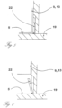
- support elements 22 are provided in the area of the shaft floor 5. The elevator car 13 cannot be moved to the shaft floor 5 when the support elements 22 are used.
- the Figures 5 and 6 show a cut and enlarged view of a Figure 4 shown support element 22.
- the support element 22 arranged in the area of the shaft floor 5 can be folded down as a type of support from a wall of the elevator shaft 4. During normal operation of the elevator 9, the support element 22 rests against the wall of the elevator shaft 4. If the support element 22 is brought into the functional position, the elevator car 13 cannot be moved to the shaft floor 5.
Landscapes
- Types And Forms Of Lifts (AREA)
- Cage And Drive Apparatuses For Elevators (AREA)
- Maintenance And Inspection Apparatuses For Elevators (AREA)
- Elevator Door Apparatuses (AREA)
Priority Applications (1)
| Application Number | Priority Date | Filing Date | Title |
|---|---|---|---|
| PL11157755.7T PL2325128T5 (pl) | 2007-10-16 | 2008-09-24 | Urządzenie dźwigowe dla osób i/lub ładunków z co najmniej jedną kabiną |
Applications Claiming Priority (2)
| Application Number | Priority Date | Filing Date | Title |
|---|---|---|---|
| DE102007049737A DE102007049737A1 (de) | 2007-10-16 | 2007-10-16 | Aufzuganlage für Personen und/oder Lasten mit zumindest einer Aufzugkabine |
| EP08016763.8A EP2050703B1 (de) | 2007-10-16 | 2008-09-24 | Aufzuganlage für Personen und/oder Lasten mit zumindest einer Aufzugkabine |
Related Parent Applications (3)
| Application Number | Title | Priority Date | Filing Date |
|---|---|---|---|
| EP08016763.8 Division | 2008-09-24 | ||
| EP08016763.8A Division-Into EP2050703B1 (de) | 2007-10-16 | 2008-09-24 | Aufzuganlage für Personen und/oder Lasten mit zumindest einer Aufzugkabine |
| EP08016763.8A Division EP2050703B1 (de) | 2007-10-16 | 2008-09-24 | Aufzuganlage für Personen und/oder Lasten mit zumindest einer Aufzugkabine |
Publications (3)
| Publication Number | Publication Date |
|---|---|
| EP2325128A1 EP2325128A1 (de) | 2011-05-25 |
| EP2325128B1 EP2325128B1 (de) | 2017-08-23 |
| EP2325128B2 true EP2325128B2 (de) | 2024-07-31 |
Family
ID=40292513
Family Applications (3)
| Application Number | Title | Priority Date | Filing Date |
|---|---|---|---|
| EP11157755.7A Active EP2325128B2 (de) | 2007-10-16 | 2008-09-24 | Aufzuganlage für Personen und/oder Lasten mit zumindest einer Aufzugkabine |
| EP08016763.8A Active EP2050703B1 (de) | 2007-10-16 | 2008-09-24 | Aufzuganlage für Personen und/oder Lasten mit zumindest einer Aufzugkabine |
| EP11157757A Withdrawn EP2325129A1 (de) | 2007-10-16 | 2008-09-24 | Aufzuganlage für Personen und/oder Lasten mit zumindest einer Aufzugkabine |
Family Applications After (2)
| Application Number | Title | Priority Date | Filing Date |
|---|---|---|---|
| EP08016763.8A Active EP2050703B1 (de) | 2007-10-16 | 2008-09-24 | Aufzuganlage für Personen und/oder Lasten mit zumindest einer Aufzugkabine |
| EP11157757A Withdrawn EP2325129A1 (de) | 2007-10-16 | 2008-09-24 | Aufzuganlage für Personen und/oder Lasten mit zumindest einer Aufzugkabine |
Country Status (4)
| Country | Link |
|---|---|
| EP (3) | EP2325128B2 (pl) |
| DE (1) | DE102007049737A1 (pl) |
| ES (2) | ES2640641T5 (pl) |
| PL (1) | PL2325128T5 (pl) |
Families Citing this family (2)
| Publication number | Priority date | Publication date | Assignee | Title |
|---|---|---|---|---|
| DE102014113341A1 (de) | 2014-09-16 | 2016-03-17 | Manfred Lienemann | Verfahren zum Betrieb einer Aufzuganlage und Aufzuganlage für Personen und/oder Lasten |
| CN108862132B (zh) * | 2018-09-27 | 2023-12-22 | 天津天玺建筑设计有限公司 | 一种适用于无电梯楼房的载人升降机 |
Family Cites Families (22)
| Publication number | Priority date | Publication date | Assignee | Title |
|---|---|---|---|---|
| US1164115A (en) | 1909-01-21 | 1915-12-14 | Charles O Pearson | Traction-elevator. |
| JPH0416472A (ja) | 1990-05-11 | 1992-01-21 | Toshiba Corp | エレベータの安全装置 |
| CA2166841C (en) | 1995-01-31 | 2006-08-22 | Heinrich Foelix | Temporary working space protection |
| US5806633A (en) * | 1995-12-22 | 1998-09-15 | Macuga; Henry J. | Elevator safety system incorporating false pit |
| FI108124B (fi) | 1998-03-18 | 2001-11-30 | Kone Corp | Hissin turvalaite |
| DE29817351U1 (de) * | 1998-09-28 | 1999-10-07 | C. Haushahn GmbH & Co., 70469 Stuttgart | Vorrichtung zum Sonderbetrieb von Aufzugsanlagen |
| US6202797B1 (en) * | 1999-08-26 | 2001-03-20 | Otis Elevator Company | Automatic protection of elevator mechanics |
| US6223681B1 (en) | 1999-09-07 | 2001-05-01 | The United States Of America As Represented By The Secretary Of The Navy | REMUS positive lock securing apparatus |
| EP1110900B2 (en) * | 1999-12-20 | 2011-07-27 | Mitsubishi Elevator Europe B.V. | Shaft safety system for an elevator |
| JP2002167137A (ja) * | 2000-11-29 | 2002-06-11 | Toshiba Corp | エレベータ |
| FI112640B (fi) * | 2000-12-22 | 2003-12-31 | Kone Corp | Hissin turvalaite |
| FI115625B (fi) | 2001-08-13 | 2005-06-15 | Kone Corp | Menetelmä ja järjestely turvatilan muodostamiseksi hissikuilun alaosaan |
| EP1333000A1 (en) * | 2002-02-05 | 2003-08-06 | Monitor S.p.A. | A machine-roomless traction sheave elevator |
| JP2003306277A (ja) * | 2002-04-12 | 2003-10-28 | Toshiba Elevator Co Ltd | エレベータのメンテナンスシステム |
| PE20040794A1 (es) | 2003-03-05 | 2004-12-22 | Inventio Ag | Prevencion de acceso no autorizado a cajas de ascensor |
| NZ532767A (en) | 2003-05-21 | 2004-12-24 | Inventio Ag | Lift installation with a buffer for creating a zone of protection in a lift installation and a method of creating a zone of protection |
| EP1710196B1 (en) * | 2004-01-27 | 2012-08-08 | Mitsubishi Denki Kabushiki Kaisha | Drive unit for elevator apparatus, elevator apparatus, installation method of elevator apparatus, and maintenance/inspection method of elevator apparatus |
| US7258202B1 (en) * | 2004-05-10 | 2007-08-21 | Inventio Ag | Creation of temporary safety spaces for elevators |
| CN101084157B (zh) * | 2004-12-21 | 2010-04-14 | 奥蒂斯电梯公司 | 电梯安全系统及其防止人员受伤的方法 |
| DE202005016050U1 (de) | 2005-07-21 | 2006-11-30 | Exclusive Lift Gmbh | Aufzug für Personen und/oder Lasten mit zumindest einer Aufzugskabine |
| DE102005047499A1 (de) | 2005-10-04 | 2007-04-12 | Wittur Ag | Aufzug (Rucksackaufzug mit am Fahrkorbrahmen aufgehängter Kabine) |
| US7954606B2 (en) | 2005-10-05 | 2011-06-07 | Otis Elevator Company | Elevator system control responsive to hoistway access detection |
-
2007
- 2007-10-16 DE DE102007049737A patent/DE102007049737A1/de active Pending
-
2008
- 2008-09-24 EP EP11157755.7A patent/EP2325128B2/de active Active
- 2008-09-24 PL PL11157755.7T patent/PL2325128T5/pl unknown
- 2008-09-24 EP EP08016763.8A patent/EP2050703B1/de active Active
- 2008-09-24 ES ES11157755T patent/ES2640641T5/es active Active
- 2008-09-24 EP EP11157757A patent/EP2325129A1/de not_active Withdrawn
- 2008-09-24 ES ES08016763T patent/ES2720861T3/es active Active
Also Published As
| Publication number | Publication date |
|---|---|
| EP2325129A1 (de) | 2011-05-25 |
| DE102007049737A1 (de) | 2009-04-23 |
| EP2050703A2 (de) | 2009-04-22 |
| EP2050703B1 (de) | 2019-02-13 |
| EP2325128B1 (de) | 2017-08-23 |
| EP2050703A3 (de) | 2009-07-22 |
| ES2720861T3 (es) | 2019-07-25 |
| ES2640641T5 (es) | 2024-12-10 |
| PL2325128T5 (pl) | 2024-11-12 |
| ES2640641T3 (es) | 2017-11-03 |
| PL2325128T3 (pl) | 2018-01-31 |
| EP2325128A1 (de) | 2011-05-25 |
Similar Documents
| Publication | Publication Date | Title |
|---|---|---|
| DE69926244T2 (de) | Schachtsicherheitssystem für Aufzug | |
| WO2012126618A1 (de) | Lift mit minimaler liftschacht-grubentiefe und mit permanentem schutzraum | |
| EP2581334B1 (de) | Absturzschutz für Aufzugsanlagen | |
| EP1854758B1 (de) | Aufzugfahrkorb | |
| EP1772414B1 (de) | Faltbare selbsthemmende Fahrkorbschürze | |
| EP0922663B1 (de) | Aufzug, insbesondere Treibscheibenaufzug | |
| EP3003944A1 (de) | Aufzugsschacht mit verkleinerter schachtgrube bzw. verkleinertem schachtkopf | |
| DE10065101A1 (de) | Aufzug mit einer Schutzvorrichtung | |
| EP2325128B2 (de) | Aufzuganlage für Personen und/oder Lasten mit zumindest einer Aufzugkabine | |
| DE102008038409B4 (de) | Vorrichtung zur Sicherung von Schachtzugängen von Aufzugsanlagen | |
| EP2730478A2 (de) | Schienenfahrzeug mit einer Hubliftplattform im Einstiegsbereich | |
| AT517871A1 (de) | Aufzugskabine | |
| EP1674416B1 (de) | Aufzug und Fahrkorb | |
| CH714341B1 (de) | Aufzugsanlage mit einer Kabine umfassend eine Auffangeinrichtung. | |
| EP1053202A1 (de) | Sicherheitseinrichtung für bauaufzug | |
| DE20105488U1 (de) | Temporärer Schutzraum im Aufzugsschacht ,aktivierbar von der Kabine aus | |
| EP0710137B1 (de) | Sicherheitseinrichtung für notausstiege | |
| DE102022114451B4 (de) | Notabseilvorrichtung für Bauwerke | |
| DE102005007475B3 (de) | Personenlift | |
| DE20202775U1 (de) | Aufzug mit einem temporären Schutzraum | |
| DE102006045499A1 (de) | Fahrkorbschürze mit Sicherheitsfunktion | |
| EP1602615A1 (de) | Sicherheitseinrichtung zum Festsetzen einer Aufzugskabine | |
| CH704628B1 (de) | Lift mit minimaler Liftschacht-Grubentiefe und mit permanentem Schutzraum. | |
| CH702838B1 (de) | Lift, mit geschlossener Kabine im Servicemodus fahrbar. | |
| DE10065099A1 (de) | Schutzvorrichtung zur Erzeugung eines Schutzraumes |
Legal Events
| Date | Code | Title | Description |
|---|---|---|---|
| PUAI | Public reference made under article 153(3) epc to a published international application that has entered the european phase |
Free format text: ORIGINAL CODE: 0009012 |
|
| AC | Divisional application: reference to earlier application |
Ref document number: 2050703 Country of ref document: EP Kind code of ref document: P |
|
| AK | Designated contracting states |
Kind code of ref document: A1 Designated state(s): AT BE BG CH CY CZ DE DK EE ES FI FR GB GR HR HU IE IS IT LI LT LU LV MC MT NL NO PL PT RO SE SI SK TR |
|
| AX | Request for extension of the european patent |
Extension state: AL BA MK RS |
|
| 17P | Request for examination filed |
Effective date: 20111124 |
|
| RAP1 | Party data changed (applicant data changed or rights of an application transferred) |
Owner name: INVENTIO AG |
|
| REG | Reference to a national code |
Ref country code: DE Ref legal event code: R079 Ref document number: 502008015562 Country of ref document: DE Free format text: PREVIOUS MAIN CLASS: B66B0011000000 Ipc: B66B0017340000 |
|
| GRAP | Despatch of communication of intention to grant a patent |
Free format text: ORIGINAL CODE: EPIDOSNIGR1 |
|
| STAA | Information on the status of an ep patent application or granted ep patent |
Free format text: STATUS: GRANT OF PATENT IS INTENDED |
|
| RIC1 | Information provided on ipc code assigned before grant |
Ipc: B66B 5/00 20060101ALI20170222BHEP Ipc: B66B 17/34 20060101AFI20170222BHEP |
|
| INTG | Intention to grant announced |
Effective date: 20170314 |
|
| RIN1 | Information on inventor provided before grant (corrected) |
Inventor name: LIENEMANN, MANFRED |
|
| GRAS | Grant fee paid |
Free format text: ORIGINAL CODE: EPIDOSNIGR3 |
|
| GRAA | (expected) grant |
Free format text: ORIGINAL CODE: 0009210 |
|
| STAA | Information on the status of an ep patent application or granted ep patent |
Free format text: STATUS: THE PATENT HAS BEEN GRANTED |
|
| AC | Divisional application: reference to earlier application |
Ref document number: 2050703 Country of ref document: EP Kind code of ref document: P |
|
| AK | Designated contracting states |
Kind code of ref document: B1 Designated state(s): AT BE BG CH CY CZ DE DK EE ES FI FR GB GR HR HU IE IS IT LI LT LU LV MC MT NL NO PL PT RO SE SI SK TR |
|
| REG | Reference to a national code |
Ref country code: GB Ref legal event code: FG4D Free format text: NOT ENGLISH |
|
| REG | Reference to a national code |
Ref country code: CH Ref legal event code: EP |
|
| REG | Reference to a national code |
Ref country code: AT Ref legal event code: REF Ref document number: 921102 Country of ref document: AT Kind code of ref document: T Effective date: 20170915 |
|
| REG | Reference to a national code |
Ref country code: IE Ref legal event code: FG4D Free format text: LANGUAGE OF EP DOCUMENT: GERMAN |
|
| REG | Reference to a national code |
Ref country code: DE Ref legal event code: R096 Ref document number: 502008015562 Country of ref document: DE Ref country code: FR Ref legal event code: PLFP Year of fee payment: 10 |
|
| REG | Reference to a national code |
Ref country code: ES Ref legal event code: FG2A Ref document number: 2640641 Country of ref document: ES Kind code of ref document: T3 Effective date: 20171103 |
|
| REG | Reference to a national code |
Ref country code: NL Ref legal event code: FP |
|
| REG | Reference to a national code |
Ref country code: LT Ref legal event code: MG4D |
|
| PG25 | Lapsed in a contracting state [announced via postgrant information from national office to epo] |
Ref country code: NO Free format text: LAPSE BECAUSE OF FAILURE TO SUBMIT A TRANSLATION OF THE DESCRIPTION OR TO PAY THE FEE WITHIN THE PRESCRIBED TIME-LIMIT Effective date: 20171123 Ref country code: SE Free format text: LAPSE BECAUSE OF FAILURE TO SUBMIT A TRANSLATION OF THE DESCRIPTION OR TO PAY THE FEE WITHIN THE PRESCRIBED TIME-LIMIT Effective date: 20170823 Ref country code: FI Free format text: LAPSE BECAUSE OF FAILURE TO SUBMIT A TRANSLATION OF THE DESCRIPTION OR TO PAY THE FEE WITHIN THE PRESCRIBED TIME-LIMIT Effective date: 20170823 Ref country code: LT Free format text: LAPSE BECAUSE OF FAILURE TO SUBMIT A TRANSLATION OF THE DESCRIPTION OR TO PAY THE FEE WITHIN THE PRESCRIBED TIME-LIMIT Effective date: 20170823 Ref country code: HR Free format text: LAPSE BECAUSE OF FAILURE TO SUBMIT A TRANSLATION OF THE DESCRIPTION OR TO PAY THE FEE WITHIN THE PRESCRIBED TIME-LIMIT Effective date: 20170823 |
|
| PG25 | Lapsed in a contracting state [announced via postgrant information from national office to epo] |
Ref country code: LV Free format text: LAPSE BECAUSE OF FAILURE TO SUBMIT A TRANSLATION OF THE DESCRIPTION OR TO PAY THE FEE WITHIN THE PRESCRIBED TIME-LIMIT Effective date: 20170823 Ref country code: GR Free format text: LAPSE BECAUSE OF FAILURE TO SUBMIT A TRANSLATION OF THE DESCRIPTION OR TO PAY THE FEE WITHIN THE PRESCRIBED TIME-LIMIT Effective date: 20171124 Ref country code: IS Free format text: LAPSE BECAUSE OF FAILURE TO SUBMIT A TRANSLATION OF THE DESCRIPTION OR TO PAY THE FEE WITHIN THE PRESCRIBED TIME-LIMIT Effective date: 20171223 Ref country code: BG Free format text: LAPSE BECAUSE OF FAILURE TO SUBMIT A TRANSLATION OF THE DESCRIPTION OR TO PAY THE FEE WITHIN THE PRESCRIBED TIME-LIMIT Effective date: 20171123 |
|
| PG25 | Lapsed in a contracting state [announced via postgrant information from national office to epo] |
Ref country code: DK Free format text: LAPSE BECAUSE OF FAILURE TO SUBMIT A TRANSLATION OF THE DESCRIPTION OR TO PAY THE FEE WITHIN THE PRESCRIBED TIME-LIMIT Effective date: 20170823 Ref country code: RO Free format text: LAPSE BECAUSE OF FAILURE TO SUBMIT A TRANSLATION OF THE DESCRIPTION OR TO PAY THE FEE WITHIN THE PRESCRIBED TIME-LIMIT Effective date: 20170823 |
|
| REG | Reference to a national code |
Ref country code: DE Ref legal event code: R026 Ref document number: 502008015562 Country of ref document: DE |
|
| PLBI | Opposition filed |
Free format text: ORIGINAL CODE: 0009260 |
|
| PG25 | Lapsed in a contracting state [announced via postgrant information from national office to epo] |
Ref country code: SK Free format text: LAPSE BECAUSE OF FAILURE TO SUBMIT A TRANSLATION OF THE DESCRIPTION OR TO PAY THE FEE WITHIN THE PRESCRIBED TIME-LIMIT Effective date: 20170823 Ref country code: EE Free format text: LAPSE BECAUSE OF FAILURE TO SUBMIT A TRANSLATION OF THE DESCRIPTION OR TO PAY THE FEE WITHIN THE PRESCRIBED TIME-LIMIT Effective date: 20170823 Ref country code: MC Free format text: LAPSE BECAUSE OF FAILURE TO SUBMIT A TRANSLATION OF THE DESCRIPTION OR TO PAY THE FEE WITHIN THE PRESCRIBED TIME-LIMIT Effective date: 20170823 |
|
| PLAX | Notice of opposition and request to file observation + time limit sent |
Free format text: ORIGINAL CODE: EPIDOSNOBS2 |
|
| 26 | Opposition filed |
Opponent name: OTIS ELEVATOR COMPANY Effective date: 20180522 |
|
| REG | Reference to a national code |
Ref country code: IE Ref legal event code: MM4A |
|
| REG | Reference to a national code |
Ref country code: BE Ref legal event code: MM Effective date: 20170930 |
|
| PG25 | Lapsed in a contracting state [announced via postgrant information from national office to epo] |
Ref country code: LU Free format text: LAPSE BECAUSE OF NON-PAYMENT OF DUE FEES Effective date: 20170924 |
|
| GBPC | Gb: european patent ceased through non-payment of renewal fee |
Effective date: 20171123 |
|
| PG25 | Lapsed in a contracting state [announced via postgrant information from national office to epo] |
Ref country code: IE Free format text: LAPSE BECAUSE OF NON-PAYMENT OF DUE FEES Effective date: 20170924 |
|
| PG25 | Lapsed in a contracting state [announced via postgrant information from national office to epo] |
Ref country code: SI Free format text: LAPSE BECAUSE OF FAILURE TO SUBMIT A TRANSLATION OF THE DESCRIPTION OR TO PAY THE FEE WITHIN THE PRESCRIBED TIME-LIMIT Effective date: 20170823 Ref country code: BE Free format text: LAPSE BECAUSE OF NON-PAYMENT OF DUE FEES Effective date: 20170930 |
|
| REG | Reference to a national code |
Ref country code: FR Ref legal event code: PLFP Year of fee payment: 11 |
|
| PG25 | Lapsed in a contracting state [announced via postgrant information from national office to epo] |
Ref country code: MT Free format text: LAPSE BECAUSE OF FAILURE TO SUBMIT A TRANSLATION OF THE DESCRIPTION OR TO PAY THE FEE WITHIN THE PRESCRIBED TIME-LIMIT Effective date: 20170823 |
|
| PLBB | Reply of patent proprietor to notice(s) of opposition received |
Free format text: ORIGINAL CODE: EPIDOSNOBS3 |
|
| PG25 | Lapsed in a contracting state [announced via postgrant information from national office to epo] |
Ref country code: GB Free format text: LAPSE BECAUSE OF NON-PAYMENT OF DUE FEES Effective date: 20171123 |
|
| PLAB | Opposition data, opponent's data or that of the opponent's representative modified |
Free format text: ORIGINAL CODE: 0009299OPPO |
|
| R26 | Opposition filed (corrected) |
Opponent name: OTIS ELEVATOR COMPANY Effective date: 20180522 |
|
| PG25 | Lapsed in a contracting state [announced via postgrant information from national office to epo] |
Ref country code: HU Free format text: LAPSE BECAUSE OF FAILURE TO SUBMIT A TRANSLATION OF THE DESCRIPTION OR TO PAY THE FEE WITHIN THE PRESCRIBED TIME-LIMIT; INVALID AB INITIO Effective date: 20080924 |
|
| PG25 | Lapsed in a contracting state [announced via postgrant information from national office to epo] |
Ref country code: CY Free format text: LAPSE BECAUSE OF NON-PAYMENT OF DUE FEES Effective date: 20170823 |
|
| PG25 | Lapsed in a contracting state [announced via postgrant information from national office to epo] |
Ref country code: TR Free format text: LAPSE BECAUSE OF FAILURE TO SUBMIT A TRANSLATION OF THE DESCRIPTION OR TO PAY THE FEE WITHIN THE PRESCRIBED TIME-LIMIT Effective date: 20170823 |
|
| PG25 | Lapsed in a contracting state [announced via postgrant information from national office to epo] |
Ref country code: PT Free format text: LAPSE BECAUSE OF FAILURE TO SUBMIT A TRANSLATION OF THE DESCRIPTION OR TO PAY THE FEE WITHIN THE PRESCRIBED TIME-LIMIT Effective date: 20170823 |
|
| APBM | Appeal reference recorded |
Free format text: ORIGINAL CODE: EPIDOSNREFNO |
|
| APBP | Date of receipt of notice of appeal recorded |
Free format text: ORIGINAL CODE: EPIDOSNNOA2O |
|
| APAH | Appeal reference modified |
Free format text: ORIGINAL CODE: EPIDOSCREFNO |
|
| APBQ | Date of receipt of statement of grounds of appeal recorded |
Free format text: ORIGINAL CODE: EPIDOSNNOA3O |
|
| RAP4 | Party data changed (patent owner data changed or rights of a patent transferred) |
Owner name: INVENTIO AG |
|
| APAH | Appeal reference modified |
Free format text: ORIGINAL CODE: EPIDOSCREFNO |
|
| P01 | Opt-out of the competence of the unified patent court (upc) registered |
Effective date: 20230516 |
|
| APBU | Appeal procedure closed |
Free format text: ORIGINAL CODE: EPIDOSNNOA9O |
|
| PUAH | Patent maintained in amended form |
Free format text: ORIGINAL CODE: 0009272 |
|
| STAA | Information on the status of an ep patent application or granted ep patent |
Free format text: STATUS: PATENT MAINTAINED AS AMENDED |
|
| 27A | Patent maintained in amended form |
Effective date: 20240731 |
|
| AK | Designated contracting states |
Kind code of ref document: B2 Designated state(s): AT BE BG CH CY CZ DE DK EE ES FI FR GB GR HR HU IE IS IT LI LT LU LV MC MT NL NO PL PT RO SE SI SK TR |
|
| REG | Reference to a national code |
Ref country code: DE Ref legal event code: R102 Ref document number: 502008015562 Country of ref document: DE |
|
| REG | Reference to a national code |
Ref country code: NL Ref legal event code: FP |
|
| PGFP | Annual fee paid to national office [announced via postgrant information from national office to epo] |
Ref country code: FR Payment date: 20240925 Year of fee payment: 17 |
|
| PGFP | Annual fee paid to national office [announced via postgrant information from national office to epo] |
Ref country code: NL Payment date: 20240925 Year of fee payment: 17 |
|
| PGFP | Annual fee paid to national office [announced via postgrant information from national office to epo] |
Ref country code: CZ Payment date: 20240912 Year of fee payment: 17 |
|
| PGFP | Annual fee paid to national office [announced via postgrant information from national office to epo] |
Ref country code: AT Payment date: 20240917 Year of fee payment: 17 |
|
| REG | Reference to a national code |
Ref country code: ES Ref legal event code: DC2A Ref document number: 2640641 Country of ref document: ES Kind code of ref document: T5 Effective date: 20241210 |
|
| REG | Reference to a national code |
Ref country code: DE Ref legal event code: R084 Ref document number: 502008015562 Country of ref document: DE |
|
| REG | Reference to a national code |
Ref country code: CH Ref legal event code: U11 Free format text: ST27 STATUS EVENT CODE: U-0-0-U10-U11 (AS PROVIDED BY THE NATIONAL OFFICE) Effective date: 20251001 |
|
| PGFP | Annual fee paid to national office [announced via postgrant information from national office to epo] |
Ref country code: DE Payment date: 20250926 Year of fee payment: 18 |
|
| PGFP | Annual fee paid to national office [announced via postgrant information from national office to epo] |
Ref country code: PL Payment date: 20250911 Year of fee payment: 18 Ref country code: IT Payment date: 20250922 Year of fee payment: 18 |
|
| PGFP | Annual fee paid to national office [announced via postgrant information from national office to epo] |
Ref country code: CH Payment date: 20251001 Year of fee payment: 18 |
|
| PGFP | Annual fee paid to national office [announced via postgrant information from national office to epo] |
Ref country code: ES Payment date: 20251015 Year of fee payment: 18 |
|
| PG25 | Lapsed in a contracting state [announced via postgrant information from national office to epo] |
Ref country code: CZ Free format text: LAPSE BECAUSE OF NON-PAYMENT OF DUE FEES Effective date: 20250924 |