EP2320719B1 - Dichtungsstruktur für eine elektronische vorrichtung - Google Patents
Dichtungsstruktur für eine elektronische vorrichtung Download PDFInfo
- Publication number
- EP2320719B1 EP2320719B1 EP09809751.2A EP09809751A EP2320719B1 EP 2320719 B1 EP2320719 B1 EP 2320719B1 EP 09809751 A EP09809751 A EP 09809751A EP 2320719 B1 EP2320719 B1 EP 2320719B1
- Authority
- EP
- European Patent Office
- Prior art keywords
- gasket
- case
- lid
- shape
- integrated
- Prior art date
- Legal status (The legal status is an assumption and is not a legal conclusion. Google has not performed a legal analysis and makes no representation as to the accuracy of the status listed.)
- Not-in-force
Links
Images


Classifications
-
- F—MECHANICAL ENGINEERING; LIGHTING; HEATING; WEAPONS; BLASTING
- F16—ENGINEERING ELEMENTS AND UNITS; GENERAL MEASURES FOR PRODUCING AND MAINTAINING EFFECTIVE FUNCTIONING OF MACHINES OR INSTALLATIONS; THERMAL INSULATION IN GENERAL
- F16J—PISTONS; CYLINDERS; SEALINGS
- F16J15/00—Sealings
- F16J15/02—Sealings between relatively-stationary surfaces
- F16J15/06—Sealings between relatively-stationary surfaces with solid packing compressed between sealing surfaces
- F16J15/10—Sealings between relatively-stationary surfaces with solid packing compressed between sealing surfaces with non-metallic packing
- F16J15/104—Sealings between relatively-stationary surfaces with solid packing compressed between sealing surfaces with non-metallic packing characterised by structure
-
- H—ELECTRICITY
- H05—ELECTRIC TECHNIQUES NOT OTHERWISE PROVIDED FOR
- H05K—PRINTED CIRCUITS; CASINGS OR CONSTRUCTIONAL DETAILS OF ELECTRIC APPARATUS; MANUFACTURE OF ASSEMBLAGES OF ELECTRICAL COMPONENTS
- H05K5/00—Casings, cabinets or drawers for electric apparatus
- H05K5/06—Hermetically-sealed casings
- H05K5/061—Hermetically-sealed casings sealed by a gasket held between a removable cover and a body, e.g. O-ring, packing
Definitions
- the present invention relates to a seal structure for an electronic equipment, and more particularly to a seal structure to prevent a water droplet from entering into an inner portion of the electronic equipment such as a cellular phone user terminal or the like. Accordingly, the seal structure in accordance with the present invention is preferably utilized as a seal structure for a waterproofed electronic equipment.
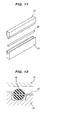
- a casing is formed by a combination of a case and a lid which are fitted to each other, and a gasket 31 constructed by an 0-ring or the like made of rubber only is interposed between a case 11 and a lid 21 as partly shown in Fig. 11 to prevent a water droplet from entering into an inner portion of the casing (refer to Patent Document 1). Further, since downsizing and thinning of the casing are now demanded, the gasket 31 is required to have a small cross sectional shape and a low hardness in order to make a burden to the casing as small as possible.
- the gasket 31 is made to have a small cross sectional shape and a low hardness as mentioned above, a rigidity of the gasket 31 itself is lowered, and a handling performance (a handling and working property) is lowered. Accordingly, an operating efficiency of a user terminal assembling step is deteriorated in addition to an assembling work of the gasket 31.
- reaction force of the gasket 31 becomes higher since a rate of the thickness of the resin film 41 to the height dimension of the gasket 31 is comparatively large. Accordingly, much load is applied to the casing due to the reaction force, and there is fear that the casing may be broken.
- Patent Document 1 Japanese Unexamined Patent Publication No. 11-54950 ( Fig. 12 ), published as JP H1154950 .
- Document JP 2005 195 138 A shows the features of the preamble of claims 1 and 6.
- the present invention is made by taking the points mentioned above into consideration, and an object of the present invention is to provide such a seal structure for an electronic equipment that a resin film is integrated with a gasket for enhancing a shape retaining property of a rubber only gasket, reaction force of the gasket does not become higher even by the integration of the resin film and the gasket, a casing of the electronic equipment is thus not broken by high reaction force of the gasket, and the casing can be easily assembled. Further, an additional object of the present invention is to provide a seal structure for an electronic equipment in which the same effect can be achieved by using a resin molded component in place of the resin film.
- a seal structure for sealing between a case and a lid which are combined with each other so as to form a casing of an electronic equipment comprising:
- the seal structure as described in claim 1 wherein the gasket and the resin film are integrated by a mechanical means, that is, are integrated by integral molding via through holes provided at a predetermined pitch in the resin film, or integral molding via come-off preventing anchor shaped parts provided at an end portion of the resin film.
- the seal structure as described in claim 1, 2, 3 or 4 wherein the installation position between the case and the lid at which the gasket is installed in the non-adhesion manner is formed in a groove shape having side wall portions at both sides in a width direction, a height of one side wall portion is set lower than that of the other side wall portion, the resin film is integrated with the gasket at a predetermined height position from a bottom surface portion of the gasket, and the resin film has such a structure that a part thereof is mounted on the one side wall portion when the gasket is installed to the groove.
- a seal structure for sealing between a case and a lid which are combined with each other so as to form a casing of an electronic equipment comprising:
- an installation position between the case and the lid at which the gasket is installed in the non-adhesion manner is formed in a 3-D shape which has a predetermined planar shape and whose height position changes in an overlapping direction of the case and the lid, and the gasket and the resin molded component are manufactured in the same 3-D shape as that of the installation position
- the gasket has the non-compressed portion, in addition to the portion which is compressed between the case and the lid when the case and the lid are assembled, and the resin film is integrated with the non-compressed portion, like as the seal structure in accordance with the present invention having the structure mentioned above, there is constructed the seal structure in which the existence of the resin film does not affect the magnitude of the gasket reaction force at all. Accordingly, it is possible to provide the seal structure in which the gasket reaction force is not enhanced in spite that the shape retaining property of the gasket is enhanced by the integration of the resin film (claim 1).
- the integration structure by the former chemical means is specifically structured such that the gasket and the resin film are adhered by the adhesive agent which is previously applied to the resin film, or the gasket and the resin film are adhered on the basis of the self-adhesiveness of the self-adhesive rubber used as the material of the gasket to. In any event, it is possible to firmly couple the gasket and the resin film (claim 2).
- the integration structure by the latter mechanical means is structured specifically such that the gasket and the resin film are integrally molded via the through holes provided at a predetermined pitch in the resin film, or the gasket and the resin film are integrally molded via the come-off preventing anchor shaped parts at the end portion of the resin film. After all, it is possible to firmly couple the gasket and the resin film in any event (claim 3).
- the installation position to which the gasket is installed in the non-adhesion manner is formed in a 3-D shape (three dimensional shape) which has a predetermined planar shape and whose height position changes in the overlapping direction of the case and the lid.
- the flat gasket having a planar shape is installed at the 3-D shaped installation position, the gasket is deformed by force after the installation, so that there is fear of a seal breakage, a gasket breakage, or the like due to an installation defect.
- the installation defect is hardly caused (seating of the gasket with respect to the installation position becomes better) (claim 4).
- the installation position at which the gasket is installed in the non-adhesion manner is formed in the groove shape having the side wall portions at both sides in the width direction, the height of the one side wall portion is set lower than that of the other side wall portion, the film is integrated with the gasket at the predetermined height position from the bottom surface portion of the gasket, and the film has such the structure that a part thereof is mounted on the one side wall portion when the gasket is installed to the groove, seating of the gasket (including the film) with respect to the installation position becomes better similarly to the above, and the installation defect is hardly caused (claim 5).
- the resin molded component is used in place of the resin film integrated with the gasket, for enhancing the shape retaining property of the gasket, and the resin molded component is integrated with the gasket (claim 6).
- the resin molded component is a three-dimensionally shaped part having a predetermined height dimension in place of the film shaped plane shaped part, and shape retaining force with respect to the gasket is larger than the resin film on the basis of its shape or volume.
- the gasket is integrated by the insert molding in which the gasket is molded in the metal mold in the state that the resin molded component previously manufactured in the product shape is inserted into the cavity space of the gasket forming metal mold (claim 7).
- the installation position between the case and the lid to which the gasket is installed in the non-adhesion manner is formed in a 3-D shape which has a predetermined planar shape and whose height position changes in the overlapping direction of the case and the lid, it is preferable to manufacture the gasket and the resin molded component in the same 3-D shape.
- the gasket since the gasket is not deformed by force after the installation, the installation defect is hardly caused (seating of the gasket with respect to the installation position becomes better) (claim 8).
- the resin molded component is thicker than the resin film so as to have a sufficient rigidity, it is possible to easily carry out an installation work in such a manner as to fit it to the casing.
- it is general to provide the groove at the installation position of the casing and insert the integrated component into the groove, in the case of the integrated component of the gasket and the resin film.
- the step may be provided and the integrated component may be fitted to the inner side of the step. Claim 9 defines this.
- the installation position between the case and the lid at which the gasket is installed in the non-adhesion manner is formed in such the step shape that one side wall portion is omitted from the groove shape having the side wall portions at both sides in the width direction, and the resin molded component is arranged at the position corresponding to that of the omitted one side wall portion when the integrated component of the gasket and the resin molded component is installed at the installation position.
- the installing work can be made easy, and the resin molded component performs a function of the groove wall, it is possible to achieve a space saving.
- the present invention achieves the following effects.
- the gasket since the gasket has the non-compression portion, in addition to the portion which is compressed between the case and the lid when the case and the lid are assembled, and the resin film is integrated with the non-compressed portion, there is constructed the seal structure in which the existence of the resin film does not affect the magnitude of the gasket reaction force at all. Accordingly, it is possible to enhance the shape retaining property of the gasket on the basis of the integration of the resin film and, in spite thereof, it is possible to provide the seal structure in which the gasket reaction force is not enhanced. Therefore, it is possible to prevent the casing from being broken on the basis of high reaction force of the gasket, and it is possible to make assembling of the casing easy (since it is not necessary to assemble the case and the lid against the high reaction force).
- the installation position at which the gasket is installed in the non-adhesion manner is formed in the groove shape having the side wall portions at both sides in the width direction, the height of the one side wall portion is set lower than that of the other side wall portion, the film is integrated with the gasket at the predetermined height position from the bottom surface portion of the gasket, and the film has such the structure that a part of the film is mounted on the one side wall portion when the gasket is installed to the groove, seating of the gasket with respect to the installation groove becomes better similarly, and the installation defect of the gasket is hardly caused.
- the seal structure in accordance with the present invention having the structure mentioned above, since the gasket has the non-compressed portion, in addition to the portion which is compressed between the case and the lid when the case and the lid are assembled, and the resin molded component is integrated with the non-compressed portion, there is constructed the seal structure in which the existence of the resin molded component does not affect the magnitude of the gasket reaction force at all. Accordingly, it is possible to enhance the shape retaining property of the gasket on the basis of the integration of the resin molded component and, in spite thereof, it is possible to provide the seal structure in which the gasket reaction force is not enhanced. Therefore, it is possible to prevent the casing from being broken on the basis of high reaction force of the gasket, and it is possible to make assembling of the casing easy (since it is not necessary to assemble the case and the lid against the high reaction force).
- the installation position between the case and the lid at which the gasket is installed in the non-adhesion manner is formed in such the step shape that one side wall portion is omitted from the groove shape having the side wall portions at both sides in the width direction, and the resin molded component is arranged at the position corresponding to that of the omitted one side wall portion when the integrated component of the gasket and the resin molded component are installed at the installation position, the installing work is made easy, and the resin molded component perform a function of the groove wall. Therefore, it is possible to achieve space saving.
- Fig. 1 shows an exploded perspective view of a seal structure in accordance with a first embodiment of the present invention
- Fig. 2 is a cross sectional view of a substantial part thereof.
- reference numerals 11 and 21 denote a case (a casing main body) and a lid which are fitted to each other so as to form a casing (an outer case) of a cellular phone terminal corresponding to one kind of an electronic equipment.
- a gasket 31 is installed in a non-adhesion manner between both the elements 11 and 21 so as to seal between the case 11 and the lid 21, and a resin film (a shape retaining film) 41 is integrated with the gasket 31 so as to enhance a shape retaining property of the gasket 31.
- an installation groove 12 for installing of the gasket 31 is formed in a peripheral edge portion (a side wall portion) of any one (the case 11 in the present embodiment) of the case 11 and the lid 21, the gasket 31 is installed to the installation groove 12 so as to be installed over a whole periphery of the casing, and when the case 11 and the lid 21 are assembled so as to come into contact with each other by mutually opposed surfaces 11a and 21a from an illustrated state, the gasket 31 is interposed in a state of being compressed between the case 11 and the lid 21.
- the gasket 31 is formed to have a circular cross sectional shape by a predetermined rubber-like elastic material (for example, a silicone rubber).
- a portion having the circular cross sectional shape is a seal portion 32 which is compressed between the case 11 and the lid 21 at a time of assembling of the case 11 and the lid 21, a connection portion 33 which is not compressed between the case 11 and the lid 21 at a time of the case 11 and the lid 21 being assembled is integrally formed in a projection shaped element over a whole periphery of a side surface (an inner peripheral surface) of the seal portion 32, in the gasket 31 in addition to the seal portion 32, and a resin film 41 is integrated with respect to the connection portion 33. Accordingly, the resin film 41 is coupled only to the connection portion 33, and is not embedded within a thickness of the seal portion 32.
- the resin film 41 is formed in a thin film shape as implied by the name by a predetermined resin material (for example, PI, PEN, PET), and is formed over a whole periphery of the side surface (the inner peripheral surface) of the gasket 31. Further, the resin film 41 is coupled to the connection portion 33 of the gasket 31 by a connection portion 42 which is a part (an outer peripheral portion) thereof, and a portion (an inner peripheral portion) other than the connection portion 42 is formed as an exposure portion 43 which is arranged in parallel to the gasket 31 after the installation. As shown in Fig. 1 , the exposure portion 43 may be provided with a guide hole 44 for positioning or fixing of the gasket, or the like.
- a predetermined resin material for example, PI, PEN, PET
- the gasket 31 and the resin film 41 are integrated by a chemical means, that is, are integrated by being adhered with an adhesive agent (not shown) which is previously applied to the resin film 41.
- the seal structure in accordance with the embodiment is structured such that an installation position between the case 11 and the lid 21, where the gasket 31 is installed in a non-adhesion manner, is formed to be an installation groove 12 in a shape having side wall portions 13 and 14 at both sides in a width direction, a height dimension h1 of one side wall portion 13 positioned at inner side in the casing is set lower than a height dimension h2 of the other side wall portion 14 positioned at outer side in the casing (h1 ⁇ h2), and the resin film 41 is integrated with the gasket 31 at a predetermined height position from a bottom surface portion 34 of the gasket 31, whereby the resin film 41 is mounted on the one side wall portion 13 by the partial exposure portion 43 which is a part thereof at a time of the gasket 31 being installed to the installation groove 12.
- the seal structure having the construction mentioned above is to seal between the case 11 and the lid 21 to prevent a water droplet from entering into the inner portion of the casing, and is characterized in that the following operational effect can be achieved by the construction mentioned above.
- the seal structure having the structure mentioned above, since the gasket 31 has the non-compressed projection shaped connection portion 33, in addition to the seal portion 32 which is compressed between the case 11 and the lid 21 at a time of the case 11 and the lid 21 being assembled, and the resin film 41 is integrated with respect to the non-compressed connection portion 33, there is provided the seal structure in which existence of the resin film 41 does not affect a magnitude of the gasket reaction force at all. Accordingly, it is possible to provide the seal structure in which a shape retaining property of the gasket 31 is enhanced on the basis of the integration of the resin film 41, but reaction force of the gasket 31 is not enhanced in spite thereof. Therefore, it is possible to prevent the casing from being broken due to the high reaction force of the gasket 31, and it is possible to make assembling of the casing easy.
- the gasket 31 and the resin film 41 are integrated by the chemical means, that is, are integrated by being adhered with an adhesive agent (not shown) which is previously applied to the resin film 41, the gasket 31 and the resin film 41 are firmly coupled.
- an adhesive agent not shown
- a material of the gasket 31 is a self-adhesive rubber, it is possible to adhere them on the basis of the self-adhesiveness without applying any adhesive agent.
- the installation position between the case 11 and the lid 21, at which the gasket 31 is installed in the non-adhesion manner is formed to be the installation groove 12 in the shape having the side wall portions 13 and 14 at both sides in the width direction, the height dimension h1 of the one side wall portion 13 is set lower than the height dimension h2 of the other side wall portion 14, the resin film 41 is integrated with the gasket 31 at the predetermined height position from the bottom surface portion 34 of the gasket 31, and the resin film 41 is mounted on the one side wall portion 13 by the partial exposure portion 43 which is a part thereof at a time of the gasket 31 being installed to the installation groove 12, seating of the gasket 31 with respect to the installation groove 12 becomes good, and an installation defect of the gasket 31 is hardly caused.
- the installation groove 12, the gasket 31 and the resin film 41 are all formed in a planar shape.
- the installation groove 12 is formed in a 3-D shape which has a predetermined planar shape and whose height position changes in an overlapping direction of the case 11 and the lid 21, as exemplified in Fig. 3 .
- the gasket 31 and the resin film 41 are manufactured in the same 3-D shape, by changing of a cavity shape of a gasket forming metal mold or otherwise.
- the 3-D shape is formed in such a shape that is planar from a portion A to a portion B, and becomes higher in its height position little by little from the portion B to a portion C.
- both the elements 31 and 41 are integrated by the chemical means in the first embodiment. However, in place thereof, both the elements 31 and 41 are integrated by a mechanical means.
- a lot of through holes 45 are provided at a predetermined pitch in the resin film 41, both the elements 31 and 41 are integrally formed by a metal mold, a part of the elastic material is filled in the through holes 45, thereby both the elements 31 and 41 being engaged.
- a surface roughness or the like provided by roughening of a surface of the film 41 may be used besides the above.
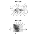
- Fig. 7 shows a perspective view of an integrated component of a gasket and a resin molded component which is used in a seal structure in accordance with a seventh embodiment of the present invention
- Figs. 8(A), 8(B) and 8(C) show a cross section of a substantial part thereof.
- Fig. 9 shows a perspective view of a state in which the integrated component is fitted to a case
- Fig. 10 shows a cross section of a substantial part of the whole of the seal structure.
- a resin molded component 51 is used in place of the resin film 41 in the first to sixth embodiments.
- the resin molded component 51 is integrated with the gasket 31 in order to enhancing the shape retaining property of the gasket 31.
- the gasket 31 is formed to have a circular cross sectional shape by a predetermined rubber-like elastic material (for example, a silicone rubber) in the same manner as each of the embodiments, however, the portion having the circular cross sectional shape is a seal portion 32 which is compressed between the case 11 and the lid 21 at a time of the case 11 and the lid 21 being assembled, a connection portion 33, which is not compressed between the case 11 and the lid 21 at a time of the case 11 and the lid 21 being assembled, is integrally formed as a projection shaped element over a whole periphery on a side surface (an inner peripheral surface) of the seal portion 32 of the gasket 31 in addition to the seal portion 32, and the resin molded component 51 is integrated with respect to the connection portion 33. Therefore, the resin molded component 51 is coupled only to the connection portion 33, and is not embedded within a thickness of the seal portion 32.
- a predetermined rubber-like elastic material for example, a silicone rubber
- the resin molded component 51 is formed as a three-dimensionally shaped part (a part having a rectangular cross sectional shape in the figures) having a predetermined height dimension by a predetermined resin material (for example, a liquid crystal polymer which can be formed thin and has a good heat resistance), and an upper surface thereof is adhered by vulcanization to a lower surface of the connection portion 33.
- the resin molded component 51 is provided over a whole periphery on a side surface (an inner peripheral surface) of the gasket 31. Further, the resin molded component 51 integrally has projection shaped engagement portions 52 for positioning or fixing of the gasket from place to place on the periphery (for example, six positions on the periphery).
- the gasket 31 and the resin molded component 51 are integrated in accordance with insert molding, that is, are integrated in accordance with insert molding in which the gasket 31 is molded by a metal mold in a state of the resin molded component 51, which is previously manufactured in a product shape, being inserted into a cavity space of the gasket forming metal mold.
- an installation position between the case 11 and the lid (not shown) to which the gasket 31 is installed in a non-adhesion manner is formed in a 3-D shape which has a predetermined planar shape and whose height position changes in an overlapping direction of the case 11 and the lid, and the integrated component of the gasket 31 and the resin molded component 51 is manufactured in the same 3-D shape in conformity thereto.
- An illustrated 3-D shape is formed such that a part of the periphery denoted by reference symbol E is lower than the other portions.
- the installation position between the case 11 and the lid 21 to which the gasket 31 is installed in a non-adhesion manner is formed in such a shape that the side wall portion 13 at one side is omitted from the groove shape (refer to Fig. 2 ) having the side wall portions 13 and 14 at both sides in the width direction (a step shape having only the side wall portion 14 at the remaining side), and is structured such that the resin molded component 51 is arranged at a position corresponding to the omitted side wall portion 13 when the integrated component of the gasket 31 and the resin molded component 51 is installed to the installation position.
- the seal structure having the construction mentioned above is to seal between the case 11 and the lid 21 to prevent the water droplet from entering into the inner portion of the casing, and is characterized in that the following operational effects can be achieved by the construction mentioned above.
- the seal structure having the construction mentioned above, since the gasket 31 has the projection shaped non-compressed connection portion 33 in addition to the seal portion 32 which is compressed between the case 11 and the lid 21 at a time of the case 11 and the lid 21 being assembled, and the resin molded component 51 is integrated with respect to the non-compressed connection portion 33, there is provided the seal structure in which the existence of the resin molded component 51 does not affect a magnitude of the gasket reaction force at all. Accordingly, it is possible to provide the seal structure in which the shape retaining property of the gasket 31 is enhanced by the integration of the resin molded component 51, but the gasket reaction force is not enhanced in spite thereof. Therefore, it is possible to prevent the casing from being broken by the high reaction force generation of the gasket 31, and it is possible to make assembling of the casing easy.
- the gasket 31 and the resin molded component 51 since the gasket 31 and the resin molded component 51 are integrated in accordance with insert molding, it is possible to easily and firmly couple the resin molded component 51 to the gasket 31.
- gasket 31 and the resin molded component 51 are manufactured in the same 3-D shape in the case that the installation position is formed in the 3-D shape, seating of the gasket 31 becomes better with respect to the installation position, and the installation defect of the gasket 31 is hardly caused.
- the installation position between the case 11 and the lid 21 to which the gasket 31 is installed in a non-adhesion manner is formed in such the shape that the side wall portion 13 at one side is omitted from the groove shape (refer to Fig. 2 ) having the side wall portions 13 and 14 at both sides in the width direction (the stepped shape having only the side wall portion 14 at the remaining side), and is structured such that the resin molded component 51 is arranged at the position corresponding to the omitted side wall portion 13 at a time of the integrated component of the gasket 31 and the resin molded component 51 being installed to the installation position, the installing work is made easy, and the resin molded component 51 performs a function of the groove wall. Accordingly, space saving can be achieved.
Landscapes
- Engineering & Computer Science (AREA)
- General Engineering & Computer Science (AREA)
- Mechanical Engineering (AREA)
- Microelectronics & Electronic Packaging (AREA)
- Casings For Electric Apparatus (AREA)
- Gasket Seals (AREA)
- Telephone Set Structure (AREA)
Claims (9)
- Dichtungsstruktur, die zwischen einem Behälter (11) und einem Deckel (21) abdichtet, die ein Gehäuse einer elektronischen Ausrüstung bildend miteinander verbunden sind, wobei die Dichtungsstruktur für die elektronische Ausrüstung aufweist:eine Dichtung (31), die in einer nicht haftenden Weise zwischen dem Behälter und Deckel einbaubar ist und in einem zusammengedrückten Zustand zwischenlegbar ist, wenn der Behälter und Deckel zusammengebaut sind; undwobei die Dichtung einen nicht zusammengedrückten Abschnitt (33) zusätzlich zu einem Abschnitt (32) hat, der zwischen dem Behälter und Deckel zusammendrückbar ist, wenn der Behälter und Deckel zusammengebaut sind, und wobei eine Harzschicht (41) mit dem nicht zusammengedrückten Abschnitt (33) einstückig ausgebildet ist, dadurch gekennzeichnet, dassdie Harzschicht (41) mit der Dichtung einstückig ausgebildet ist, um eine formstabile Eigenschaft der Dichtung zu verbessern.
- Dichtungsstruktur nach Anspruch 1, wobei die Dichtung (31) und die Harzschicht (41) durch ein chemisches Mittel einstückig ausgebildet sind, das heißt, durch Anhaften mit einem Klebstoff einstückig ausgebildet sind, der vorher auf die Harzschicht aufgetragen ist, oder basierend auf der Selbstanhaftung eines selbstklebenden Gummis, der als ein Material der Dichtung verwendet ist.
- Dichtungsstruktur nach Anspruch 1, wobei die Dichtung und die Harzschicht durch ein mechanisches Mittel einstückig ausgebildet sind, das heißt, durch einstückiges Formen über Durchgangslöcher 45 einstückig ausgebildet sind, die mit einer vorgegebenen Teilung in der Harzschicht vorgesehen sind, oder durch einstückiges Formen über eine Ablösung verhindernde ankerförmige Teile (48, 49), die an einem Endabschnitt der Harzschicht vorgesehen sind.
- Dichtungsstruktur nach Anspruch 1, 2 oder 3, wobei eine Einbauposition zwischen dem Behälter und dem Deckel, in der die Dichtung in der nicht haftenden Weise einbaubar ist, als eine 3D-Form ausgebildet ist, die eine vorgegebene ebene Form hat und deren Höhenposition sich in einer Überlappungsrichtung des Behälters und des Deckels ändert, und wobei die Dichtung und der Harzfilm als die gleiche 3D-Form hergestellt sind wie die der Einbauposition.
- Dichtungsstruktur nach Anspruch 1, 2, 3 oder 4, wobei die Einbauposition zwischen dem Behälter und dem Deckel, in der die Dichtung in der nicht haftenden Weise einbaubar ist, als eine Nutform (12) ausgebildet ist, die Seitenwandabschnitte (13, 14) an beiden Seiten in einer Breitenrichtung hat, wobei eine Höhe (h1) eines Seitenwandabschnitts (13) niedriger festgelegt ist als die des anderen Seitenwandabschnitts (14), der Harzfilm mit der Dichtung an einer vorgegebenen Höhenposition von einem Bodenflächenabschnitt der Dichtung einstückig ausgebildet ist und der Harzfilm eine solche Struktur hat, dass einer von seinen Teilen auf dem einen Seitenwandabschnitt (13) montiert ist, wenn die Dichtung in der Nut eingebaut ist.
- Dichtungsstruktur, die zwischen einem Behälter (11) und einem Deckel (21) abdichtet, die ein Gehäuse einer elektronischen Ausrüstung bildend miteinander verbunden sind, wobei die Dichtungsstruktur für die elektronische Ausrüstung aufweist:eine Dichtung (31), die in einer nicht haftenden Weise zwischen dem Behälter und Deckel einbaubar ist und in einem zusammengedrückten Zustand zwischenlegbar ist, wenn der Behälter und Deckel zusammengebaut sind; undwobei die Dichtung (31) einen nicht zusammengedrückten Abschnitt (33) zusätzlich zu einem Abschnitt hat, der zwischen dem Behälter und dem Deckel zusammendrückbar ist, wenn der Behälter und Deckel zusammengebaut sind, und wobei eine harzgeformte Komponente (51) mit dem nicht zusammengedrückten Abschnitt (33) einstückig ausgebildet ist, dadurch gekennzeichnet, dassdie harzgeformte Komponente (51) mit der Dichtung (31) einstückig ausgebildet ist, um eine formstabile Eigenschaft der Dichtung zu verbessern.
- Dichtungsstruktur nach Anspruch 6, wobei die Dichtung und die harzgeformte Komponente durch Umspritzen einstückig ausgebildet sind, bei dem die Dichtung durch eine Metallform in einem Zustand geformt ist, in dem die vorher als ein Formling hergestellte harzgeformte Komponente in einen Aussparungsbereich der die Dichtung erzeugenden Metallform eingesetzt ist.
- Dichtungsstruktur nach Anspruch 6 oder 7, wobei eine Einbauposition zwischen dem Behälter und dem Deckel, in der die Dichtung in der nicht haftenden Weise einbaubar ist, als eine 3D-Form ausgebildet ist, die eine vorgegebene ebene Form hat und deren Höhenposition sich in einer Überlappungsrichtung des Behälters und des Deckels ändert, und wobei die Dichtung und die harzgeformte Komponente als die gleiche 3D-Form hergestellt sind wie die der Einbauposition.
- Dichtungsstruktur nach einem der Ansprüche 6, 7 oder 8, wobei die Einbauposition zwischen dem Behälter und dem Deckel, in der die Dichtung in der nicht haftenden Weise einbaubar ist, als eine solche Stufenform ausgebildet ist, dass ein Seitenwandabschnitt (13) aus einer Nutform mit Seitenwandabschnitten (13, 14) an beiden Seiten in einer Breitenrichtung weggelassen ist und die harzgeformte Komponente (51) an einer Position angeordnet ist, die dem einen weggelassenen Seitenwandabschnitt (13) entspricht, wenn die einstückig ausgebildete Komponente der Dichtung und die harzgeformte Komponente in der Einbauposition eingebaut sind.
Applications Claiming Priority (3)
| Application Number | Priority Date | Filing Date | Title |
|---|---|---|---|
| JP2008217678 | 2008-08-27 | ||
| JP2009071689A JP5198335B2 (ja) | 2008-08-27 | 2009-03-24 | 電子機器のシール構造 |
| PCT/JP2009/063912 WO2010024097A1 (ja) | 2008-08-27 | 2009-08-06 | 電子機器のシール構造 |
Publications (3)
| Publication Number | Publication Date |
|---|---|
| EP2320719A1 EP2320719A1 (de) | 2011-05-11 |
| EP2320719A4 EP2320719A4 (de) | 2013-09-25 |
| EP2320719B1 true EP2320719B1 (de) | 2015-10-07 |
Family
ID=41721269
Family Applications (1)
| Application Number | Title | Priority Date | Filing Date |
|---|---|---|---|
| EP09809751.2A Not-in-force EP2320719B1 (de) | 2008-08-27 | 2009-08-06 | Dichtungsstruktur für eine elektronische vorrichtung |
Country Status (6)
| Country | Link |
|---|---|
| US (1) | US8833772B2 (de) |
| EP (1) | EP2320719B1 (de) |
| JP (1) | JP5198335B2 (de) |
| KR (1) | KR101612892B1 (de) |
| CN (1) | CN102132640B (de) |
| WO (1) | WO2010024097A1 (de) |
Families Citing this family (24)
| Publication number | Priority date | Publication date | Assignee | Title |
|---|---|---|---|---|
| NZ583590A (en) * | 2009-02-27 | 2011-09-30 | Clipsal Australia Pty Ltd | An electrical enclosure and a gasket with a hard stop for an electrical enclosure |
| JP4567798B1 (ja) * | 2009-06-04 | 2010-10-20 | 三菱電線工業株式会社 | 密封構造 |
| WO2012169068A1 (ja) | 2011-06-10 | 2012-12-13 | 富士通株式会社 | 携帯型電子機器、および、防水カバー |
| KR20130006962A (ko) * | 2011-06-28 | 2013-01-18 | 시게이트 테크놀로지 인터내셔날 | 하드디스크 드라이브 |
| US20140206420A1 (en) * | 2011-08-22 | 2014-07-24 | Nec Casio Mobile Communications, Ltd. | Waterproof structure and waterproofing method for mobile terminal device |
| JP5852481B2 (ja) * | 2012-03-19 | 2016-02-03 | シャープ株式会社 | 携帯端末 |
| TWI482000B (zh) * | 2012-11-06 | 2015-04-21 | Wistron Corp | 密封元件及應用該密封元件之電子裝置 |
| JP2014183102A (ja) * | 2013-03-18 | 2014-09-29 | Fujitsu Ltd | 電子機器 |
| JP2015001990A (ja) * | 2013-06-13 | 2015-01-05 | 日本電産株式会社 | トップカバー、ディスク駆動装置、およびトップカバーの製造方法 |
| JP2015014343A (ja) * | 2013-07-08 | 2015-01-22 | 株式会社デンソー | シール構造 |
| US20150097471A1 (en) * | 2013-10-04 | 2015-04-09 | Stevan M. Bailey | Water resistant outdoor electronics cabinet |
| JP6233257B2 (ja) * | 2014-04-15 | 2017-11-22 | トヨタ自動車株式会社 | 電力変換器 |
| EP3287673B1 (de) * | 2015-04-24 | 2021-05-05 | NOK Corporation | Dichtungsformteil und herstellungsverfahren dafür |
| KR102645670B1 (ko) * | 2015-12-24 | 2024-03-07 | 엔오케이 가부시키가이샤 | 개스킷 및 그 제조방법 및 취급방법 |
| CN206237710U (zh) * | 2016-10-27 | 2017-06-09 | 丽宝大数据股份有限公司 | 电子装置壳体防水结构 |
| US10655420B2 (en) * | 2017-03-21 | 2020-05-19 | Baker Hughes, A Ge Company, Llc | Blowout prevention system including blind shear ram |
| WO2019004111A1 (ja) * | 2017-06-30 | 2019-01-03 | オリンパス株式会社 | 弾性シール部材、弾性シール部材の固定構造および内視鏡 |
| DE102018119052A1 (de) | 2018-08-06 | 2020-02-06 | Webasto SE | Batteriegehäuse |
| WO2020069112A1 (en) * | 2018-09-28 | 2020-04-02 | Federal-Mogul Motorparts Llc | Gasket and grommet installation assembly |
| US10925196B1 (en) * | 2019-08-09 | 2021-02-16 | Microsoft Technology Licensing, Llc | Dimensionally-constrained device faraday cage |
| CN113883403B (zh) * | 2020-07-01 | 2024-11-12 | 浙江万里扬股份有限公司 | 支撑垫板、支撑垫板应用结构和支撑垫板加工方法 |
| KR20230064807A (ko) * | 2021-11-04 | 2023-05-11 | 남도금형(주) | 레독스 흐름전지 스택 플레이트 구조체 제조용 이중복합사출금형 |
| CN116940018A (zh) * | 2023-06-30 | 2023-10-24 | 芜湖天马汽车电子有限公司 | 壳体安装结构、显示装置及车辆 |
| JP7811684B1 (ja) * | 2025-06-25 | 2026-02-05 | Nok株式会社 | ガスケット、燃料電池、及び水電解装置 |
Family Cites Families (12)
| Publication number | Priority date | Publication date | Assignee | Title |
|---|---|---|---|---|
| US3026367A (en) * | 1959-05-08 | 1962-03-20 | Tech Wire Prod Inc | Shielding and mounting strip |
| JPH06201048A (ja) * | 1993-01-04 | 1994-07-19 | Three Bond Co Ltd | 組立用シール材及びその組立方法 |
| US5564714A (en) * | 1993-02-23 | 1996-10-15 | Three Bond Co., Ltd. | Rubber-like molded product with support frame |
| JPH06307549A (ja) * | 1993-04-21 | 1994-11-01 | Three Bond Co Ltd | 支持枠付きゴム状成形品 |
| JPH08145181A (ja) * | 1994-11-25 | 1996-06-04 | Uchiyama Mfg Corp | ロッカーカバーガスケットとその装着方法 |
| US20010052521A1 (en) | 1997-05-30 | 2001-12-20 | Suresh Goyal | Rugged housing for portable devices |
| TWI259501B (en) * | 2000-12-07 | 2006-08-01 | Shinetsu Polymer Co | Seal and substrate container using same |
| JP2004068998A (ja) | 2002-08-08 | 2004-03-04 | Nhk Spring Co Ltd | ガスケットの取付構造およびその取付方法 |
| JP4300015B2 (ja) | 2002-10-28 | 2009-07-22 | 株式会社東芝 | 密閉形電気機器筐体 |
| JP2005195138A (ja) * | 2004-01-09 | 2005-07-21 | Auto Network Gijutsu Kenkyusho:Kk | 筐体の防水構造 |
| KR101098775B1 (ko) * | 2004-12-15 | 2011-12-26 | 에누오케 가부시키가이샤 | 전자파 실딩용 개스킷 |
| JP4210668B2 (ja) * | 2005-05-02 | 2009-01-21 | 日本ピラー工業株式会社 | 集積パネルと流体デバイスとの接続構造 |
-
2009
- 2009-03-24 JP JP2009071689A patent/JP5198335B2/ja active Active
- 2009-08-06 US US13/059,595 patent/US8833772B2/en active Active
- 2009-08-06 EP EP09809751.2A patent/EP2320719B1/de not_active Not-in-force
- 2009-08-06 WO PCT/JP2009/063912 patent/WO2010024097A1/ja not_active Ceased
- 2009-08-06 CN CN2009801335404A patent/CN102132640B/zh active Active
- 2009-08-06 KR KR1020117005080A patent/KR101612892B1/ko not_active Expired - Fee Related
Also Published As
| Publication number | Publication date |
|---|---|
| JP5198335B2 (ja) | 2013-05-15 |
| JP2010080910A (ja) | 2010-04-08 |
| CN102132640B (zh) | 2013-12-11 |
| CN102132640A (zh) | 2011-07-20 |
| US20110140375A1 (en) | 2011-06-16 |
| US8833772B2 (en) | 2014-09-16 |
| KR20110066135A (ko) | 2011-06-16 |
| KR101612892B1 (ko) | 2016-04-15 |
| EP2320719A1 (de) | 2011-05-11 |
| EP2320719A4 (de) | 2013-09-25 |
| WO2010024097A1 (ja) | 2010-03-04 |
Similar Documents
| Publication | Publication Date | Title |
|---|---|---|
| EP2320719B1 (de) | Dichtungsstruktur für eine elektronische vorrichtung | |
| JP6379204B2 (ja) | 電子制御装置 | |
| US8937246B2 (en) | Gasket and electronic device | |
| JP4460622B1 (ja) | 携帯端末装置 | |
| KR101904079B1 (ko) | 개스킷 | |
| KR101253432B1 (ko) | 시일 구조, 전자 장치, 휴대 장치 및 시일 방법 | |
| EP2752601A1 (de) | In eine platte integrierte dichtung | |
| JP5440775B2 (ja) | 燃料電池用構成部品およびその製造方法 | |
| JP2009146909A (ja) | 燃料電池用セパレータ | |
| CN102428301A (zh) | 密封构件 | |
| EP3281760A1 (de) | Dichtung und herstellungsverfahren dafür | |
| JP2011192584A (ja) | 燃料電池用ガスケットの装着構造 | |
| JP5366791B2 (ja) | 電子部品モジュールの取付構造 | |
| CN105580158B (zh) | 用于弯曲表面结构电池单元的托盘 | |
| EP3032929B1 (de) | Gehäuse für elektronische Steuereinheit | |
| JP5348680B2 (ja) | 防水構造、及び電子機器 | |
| JP6340901B2 (ja) | 携帯電子機器および指紋センサユニット | |
| JP2009036232A (ja) | 電子機器のシール構造 | |
| JP2012253196A (ja) | 電子機器およびそれに用いるカバー部材 | |
| CN221354361U (zh) | 保护套 | |
| JP5862923B2 (ja) | ガスケット | |
| CN208007073U (zh) | 钣金密封安装结构和具有其的车辆 | |
| JP5105052B2 (ja) | 電子機器筐体の製造方法、及び電子機器筐体の構造 | |
| JP2010153230A (ja) | 嵌合構造およびこれを備えた電子機器 |
Legal Events
| Date | Code | Title | Description |
|---|---|---|---|
| PUAI | Public reference made under article 153(3) epc to a published international application that has entered the european phase |
Free format text: ORIGINAL CODE: 0009012 |
|
| 17P | Request for examination filed |
Effective date: 20110222 |
|
| AK | Designated contracting states |
Kind code of ref document: A1 Designated state(s): AT BE BG CH CY CZ DE DK EE ES FI FR GB GR HR HU IE IS IT LI LT LU LV MC MK MT NL NO PL PT RO SE SI SK SM TR |
|
| AX | Request for extension of the european patent |
Extension state: AL BA RS |
|
| RAP1 | Party data changed (applicant data changed or rights of an application transferred) |
Owner name: NIPPON MEKTRON LTD. |
|
| DAX | Request for extension of the european patent (deleted) | ||
| A4 | Supplementary search report drawn up and despatched |
Effective date: 20130823 |
|
| RIC1 | Information provided on ipc code assigned before grant |
Ipc: H05K 5/06 20060101AFI20130819BHEP Ipc: F16J 15/10 20060101ALI20130819BHEP |
|
| GRAP | Despatch of communication of intention to grant a patent |
Free format text: ORIGINAL CODE: EPIDOSNIGR1 |
|
| INTG | Intention to grant announced |
Effective date: 20150309 |
|
| GRAS | Grant fee paid |
Free format text: ORIGINAL CODE: EPIDOSNIGR3 |
|
| GRAA | (expected) grant |
Free format text: ORIGINAL CODE: 0009210 |
|
| AK | Designated contracting states |
Kind code of ref document: B1 Designated state(s): AT BE BG CH CY CZ DE DK EE ES FI FR GB GR HR HU IE IS IT LI LT LU LV MC MK MT NL NO PL PT RO SE SI SK SM TR |
|
| REG | Reference to a national code |
Ref country code: GB Ref legal event code: FG4D |
|
| REG | Reference to a national code |
Ref country code: AT Ref legal event code: REF Ref document number: 754389 Country of ref document: AT Kind code of ref document: T Effective date: 20151015 Ref country code: CH Ref legal event code: EP |
|
| REG | Reference to a national code |
Ref country code: IE Ref legal event code: FG4D |
|
| REG | Reference to a national code |
Ref country code: DE Ref legal event code: R096 Ref document number: 602009034083 Country of ref document: DE |
|
| REG | Reference to a national code |
Ref country code: NL Ref legal event code: MP Effective date: 20151007 |
|
| REG | Reference to a national code |
Ref country code: AT Ref legal event code: MK05 Ref document number: 754389 Country of ref document: AT Kind code of ref document: T Effective date: 20151007 |
|
| REG | Reference to a national code |
Ref country code: LT Ref legal event code: MG4D |
|
| PG25 | Lapsed in a contracting state [announced via postgrant information from national office to epo] |
Ref country code: NO Free format text: LAPSE BECAUSE OF FAILURE TO SUBMIT A TRANSLATION OF THE DESCRIPTION OR TO PAY THE FEE WITHIN THE PRESCRIBED TIME-LIMIT Effective date: 20160107 Ref country code: HR Free format text: LAPSE BECAUSE OF FAILURE TO SUBMIT A TRANSLATION OF THE DESCRIPTION OR TO PAY THE FEE WITHIN THE PRESCRIBED TIME-LIMIT Effective date: 20151007 Ref country code: ES Free format text: LAPSE BECAUSE OF FAILURE TO SUBMIT A TRANSLATION OF THE DESCRIPTION OR TO PAY THE FEE WITHIN THE PRESCRIBED TIME-LIMIT Effective date: 20151007 Ref country code: IT Free format text: LAPSE BECAUSE OF FAILURE TO SUBMIT A TRANSLATION OF THE DESCRIPTION OR TO PAY THE FEE WITHIN THE PRESCRIBED TIME-LIMIT Effective date: 20151007 Ref country code: NL Free format text: LAPSE BECAUSE OF FAILURE TO SUBMIT A TRANSLATION OF THE DESCRIPTION OR TO PAY THE FEE WITHIN THE PRESCRIBED TIME-LIMIT Effective date: 20151007 Ref country code: IS Free format text: LAPSE BECAUSE OF FAILURE TO SUBMIT A TRANSLATION OF THE DESCRIPTION OR TO PAY THE FEE WITHIN THE PRESCRIBED TIME-LIMIT Effective date: 20160207 Ref country code: LT Free format text: LAPSE BECAUSE OF FAILURE TO SUBMIT A TRANSLATION OF THE DESCRIPTION OR TO PAY THE FEE WITHIN THE PRESCRIBED TIME-LIMIT Effective date: 20151007 |
|
| PG25 | Lapsed in a contracting state [announced via postgrant information from national office to epo] |
Ref country code: PT Free format text: LAPSE BECAUSE OF FAILURE TO SUBMIT A TRANSLATION OF THE DESCRIPTION OR TO PAY THE FEE WITHIN THE PRESCRIBED TIME-LIMIT Effective date: 20160208 Ref country code: LV Free format text: LAPSE BECAUSE OF FAILURE TO SUBMIT A TRANSLATION OF THE DESCRIPTION OR TO PAY THE FEE WITHIN THE PRESCRIBED TIME-LIMIT Effective date: 20151007 Ref country code: AT Free format text: LAPSE BECAUSE OF FAILURE TO SUBMIT A TRANSLATION OF THE DESCRIPTION OR TO PAY THE FEE WITHIN THE PRESCRIBED TIME-LIMIT Effective date: 20151007 Ref country code: SE Free format text: LAPSE BECAUSE OF FAILURE TO SUBMIT A TRANSLATION OF THE DESCRIPTION OR TO PAY THE FEE WITHIN THE PRESCRIBED TIME-LIMIT Effective date: 20151007 Ref country code: GR Free format text: LAPSE BECAUSE OF FAILURE TO SUBMIT A TRANSLATION OF THE DESCRIPTION OR TO PAY THE FEE WITHIN THE PRESCRIBED TIME-LIMIT Effective date: 20160108 Ref country code: FI Free format text: LAPSE BECAUSE OF FAILURE TO SUBMIT A TRANSLATION OF THE DESCRIPTION OR TO PAY THE FEE WITHIN THE PRESCRIBED TIME-LIMIT Effective date: 20151007 Ref country code: PL Free format text: LAPSE BECAUSE OF FAILURE TO SUBMIT A TRANSLATION OF THE DESCRIPTION OR TO PAY THE FEE WITHIN THE PRESCRIBED TIME-LIMIT Effective date: 20151007 |
|
| REG | Reference to a national code |
Ref country code: DE Ref legal event code: R097 Ref document number: 602009034083 Country of ref document: DE |
|
| PG25 | Lapsed in a contracting state [announced via postgrant information from national office to epo] |
Ref country code: CZ Free format text: LAPSE BECAUSE OF FAILURE TO SUBMIT A TRANSLATION OF THE DESCRIPTION OR TO PAY THE FEE WITHIN THE PRESCRIBED TIME-LIMIT Effective date: 20151007 |
|
| PLBE | No opposition filed within time limit |
Free format text: ORIGINAL CODE: 0009261 |
|
| STAA | Information on the status of an ep patent application or granted ep patent |
Free format text: STATUS: NO OPPOSITION FILED WITHIN TIME LIMIT |
|
| PG25 | Lapsed in a contracting state [announced via postgrant information from national office to epo] |
Ref country code: SM Free format text: LAPSE BECAUSE OF FAILURE TO SUBMIT A TRANSLATION OF THE DESCRIPTION OR TO PAY THE FEE WITHIN THE PRESCRIBED TIME-LIMIT Effective date: 20151007 Ref country code: DK Free format text: LAPSE BECAUSE OF FAILURE TO SUBMIT A TRANSLATION OF THE DESCRIPTION OR TO PAY THE FEE WITHIN THE PRESCRIBED TIME-LIMIT Effective date: 20151007 Ref country code: EE Free format text: LAPSE BECAUSE OF FAILURE TO SUBMIT A TRANSLATION OF THE DESCRIPTION OR TO PAY THE FEE WITHIN THE PRESCRIBED TIME-LIMIT Effective date: 20151007 Ref country code: SK Free format text: LAPSE BECAUSE OF FAILURE TO SUBMIT A TRANSLATION OF THE DESCRIPTION OR TO PAY THE FEE WITHIN THE PRESCRIBED TIME-LIMIT Effective date: 20151007 Ref country code: RO Free format text: LAPSE BECAUSE OF FAILURE TO SUBMIT A TRANSLATION OF THE DESCRIPTION OR TO PAY THE FEE WITHIN THE PRESCRIBED TIME-LIMIT Effective date: 20151007 |
|
| 26N | No opposition filed |
Effective date: 20160708 |
|
| PG25 | Lapsed in a contracting state [announced via postgrant information from national office to epo] |
Ref country code: SI Free format text: LAPSE BECAUSE OF FAILURE TO SUBMIT A TRANSLATION OF THE DESCRIPTION OR TO PAY THE FEE WITHIN THE PRESCRIBED TIME-LIMIT Effective date: 20151007 |
|
| PG25 | Lapsed in a contracting state [announced via postgrant information from national office to epo] |
Ref country code: BE Free format text: LAPSE BECAUSE OF FAILURE TO SUBMIT A TRANSLATION OF THE DESCRIPTION OR TO PAY THE FEE WITHIN THE PRESCRIBED TIME-LIMIT Effective date: 20151007 |
|
| PG25 | Lapsed in a contracting state [announced via postgrant information from national office to epo] |
Ref country code: MC Free format text: LAPSE BECAUSE OF FAILURE TO SUBMIT A TRANSLATION OF THE DESCRIPTION OR TO PAY THE FEE WITHIN THE PRESCRIBED TIME-LIMIT Effective date: 20151007 |
|
| REG | Reference to a national code |
Ref country code: CH Ref legal event code: PL |
|
| GBPC | Gb: european patent ceased through non-payment of renewal fee |
Effective date: 20160806 |
|
| PG25 | Lapsed in a contracting state [announced via postgrant information from national office to epo] |
Ref country code: LI Free format text: LAPSE BECAUSE OF NON-PAYMENT OF DUE FEES Effective date: 20160831 Ref country code: CH Free format text: LAPSE BECAUSE OF NON-PAYMENT OF DUE FEES Effective date: 20160831 |
|
| REG | Reference to a national code |
Ref country code: FR Ref legal event code: ST Effective date: 20170428 |
|
| REG | Reference to a national code |
Ref country code: IE Ref legal event code: MM4A |
|
| PG25 | Lapsed in a contracting state [announced via postgrant information from national office to epo] |
Ref country code: IE Free format text: LAPSE BECAUSE OF NON-PAYMENT OF DUE FEES Effective date: 20160806 Ref country code: FR Free format text: LAPSE BECAUSE OF NON-PAYMENT OF DUE FEES Effective date: 20160831 Ref country code: GB Free format text: LAPSE BECAUSE OF NON-PAYMENT OF DUE FEES Effective date: 20160806 |
|
| PG25 | Lapsed in a contracting state [announced via postgrant information from national office to epo] |
Ref country code: LU Free format text: LAPSE BECAUSE OF NON-PAYMENT OF DUE FEES Effective date: 20160806 |
|
| PG25 | Lapsed in a contracting state [announced via postgrant information from national office to epo] |
Ref country code: CY Free format text: LAPSE BECAUSE OF FAILURE TO SUBMIT A TRANSLATION OF THE DESCRIPTION OR TO PAY THE FEE WITHIN THE PRESCRIBED TIME-LIMIT Effective date: 20151007 Ref country code: HU Free format text: LAPSE BECAUSE OF FAILURE TO SUBMIT A TRANSLATION OF THE DESCRIPTION OR TO PAY THE FEE WITHIN THE PRESCRIBED TIME-LIMIT; INVALID AB INITIO Effective date: 20090806 |
|
| PG25 | Lapsed in a contracting state [announced via postgrant information from national office to epo] |
Ref country code: MT Free format text: LAPSE BECAUSE OF NON-PAYMENT OF DUE FEES Effective date: 20160831 Ref country code: MK Free format text: LAPSE BECAUSE OF FAILURE TO SUBMIT A TRANSLATION OF THE DESCRIPTION OR TO PAY THE FEE WITHIN THE PRESCRIBED TIME-LIMIT Effective date: 20151007 Ref country code: TR Free format text: LAPSE BECAUSE OF FAILURE TO SUBMIT A TRANSLATION OF THE DESCRIPTION OR TO PAY THE FEE WITHIN THE PRESCRIBED TIME-LIMIT Effective date: 20151007 |
|
| PG25 | Lapsed in a contracting state [announced via postgrant information from national office to epo] |
Ref country code: BG Free format text: LAPSE BECAUSE OF FAILURE TO SUBMIT A TRANSLATION OF THE DESCRIPTION OR TO PAY THE FEE WITHIN THE PRESCRIBED TIME-LIMIT Effective date: 20151007 |
|
| PGFP | Annual fee paid to national office [announced via postgrant information from national office to epo] |
Ref country code: DE Payment date: 20240702 Year of fee payment: 16 |
|
| REG | Reference to a national code |
Ref country code: DE Ref legal event code: R081 Ref document number: 602009034083 Country of ref document: DE Owner name: MEKTEC CORPORATION, JP Free format text: FORMER OWNER: NIPPON MEKTRON, LTD., TOKYO, JP |
|
| REG | Reference to a national code |
Ref country code: DE Ref legal event code: R119 Ref document number: 602009034083 Country of ref document: DE |