EP2320661A2 - Entfernungsverfahren für die Codierungsverzerrung - Google Patents
Entfernungsverfahren für die Codierungsverzerrung Download PDFInfo
- Publication number
- EP2320661A2 EP2320661A2 EP10178497A EP10178497A EP2320661A2 EP 2320661 A2 EP2320661 A2 EP 2320661A2 EP 10178497 A EP10178497 A EP 10178497A EP 10178497 A EP10178497 A EP 10178497A EP 2320661 A2 EP2320661 A2 EP 2320661A2
- Authority
- EP
- European Patent Office
- Prior art keywords
- coding distortion
- block
- picture
- blocks
- coding
- Prior art date
- Legal status (The legal status is an assumption and is not a legal conclusion. Google has not performed a legal analysis and makes no representation as to the accuracy of the status listed.)
- Granted
Links
- 238000000034 method Methods 0.000 title claims description 230
- 238000013139 quantization Methods 0.000 claims description 26
- 230000033001 locomotion Effects 0.000 description 78
- 238000010586 diagram Methods 0.000 description 38
- 238000012545 processing Methods 0.000 description 30
- 238000006243 chemical reaction Methods 0.000 description 25
- 238000004891 communication Methods 0.000 description 11
- 230000005540 biological transmission Effects 0.000 description 9
- 238000001914 filtration Methods 0.000 description 8
- 230000015556 catabolic process Effects 0.000 description 6
- 238000006731 degradation reaction Methods 0.000 description 6
- 238000001514 detection method Methods 0.000 description 6
- 238000005259 measurement Methods 0.000 description 6
- 101100443238 Caenorhabditis elegans dif-1 gene Proteins 0.000 description 5
- 230000003044 adaptive effect Effects 0.000 description 5
- 238000007906 compression Methods 0.000 description 5
- 230000006835 compression Effects 0.000 description 5
- 230000000593 degrading effect Effects 0.000 description 4
- 230000005236 sound signal Effects 0.000 description 4
- 101100537098 Mus musculus Alyref gene Proteins 0.000 description 3
- 101100269674 Mus musculus Alyref2 gene Proteins 0.000 description 3
- 101150095908 apex1 gene Proteins 0.000 description 3
- 230000007423 decrease Effects 0.000 description 3
- 238000011156 evaluation Methods 0.000 description 3
- 230000001629 suppression Effects 0.000 description 3
- 238000013144 data compression Methods 0.000 description 2
- 230000001419 dependent effect Effects 0.000 description 2
- 230000000694 effects Effects 0.000 description 2
- 238000005516 engineering process Methods 0.000 description 2
- 238000012986 modification Methods 0.000 description 2
- 230000004048 modification Effects 0.000 description 2
- 238000004364 calculation method Methods 0.000 description 1
- 238000012937 correction Methods 0.000 description 1
- 239000000284 extract Substances 0.000 description 1
- 238000010295 mobile communication Methods 0.000 description 1
- 230000003287 optical effect Effects 0.000 description 1
Images


Classifications
-
- H—ELECTRICITY
- H04—ELECTRIC COMMUNICATION TECHNIQUE
- H04N—PICTORIAL COMMUNICATION, e.g. TELEVISION
- H04N19/00—Methods or arrangements for coding, decoding, compressing or decompressing digital video signals
- H04N19/80—Details of filtering operations specially adapted for video compression, e.g. for pixel interpolation
-
- G—PHYSICS
- G06—COMPUTING; CALCULATING OR COUNTING
- G06T—IMAGE DATA PROCESSING OR GENERATION, IN GENERAL
- G06T5/00—Image enhancement or restoration
-
- H—ELECTRICITY
- H04—ELECTRIC COMMUNICATION TECHNIQUE
- H04N—PICTORIAL COMMUNICATION, e.g. TELEVISION
- H04N19/00—Methods or arrangements for coding, decoding, compressing or decompressing digital video signals
- H04N19/10—Methods or arrangements for coding, decoding, compressing or decompressing digital video signals using adaptive coding
- H04N19/102—Methods or arrangements for coding, decoding, compressing or decompressing digital video signals using adaptive coding characterised by the element, parameter or selection affected or controlled by the adaptive coding
- H04N19/103—Selection of coding mode or of prediction mode
- H04N19/105—Selection of the reference unit for prediction within a chosen coding or prediction mode, e.g. adaptive choice of position and number of pixels used for prediction
-
- H—ELECTRICITY
- H04—ELECTRIC COMMUNICATION TECHNIQUE
- H04N—PICTORIAL COMMUNICATION, e.g. TELEVISION
- H04N19/00—Methods or arrangements for coding, decoding, compressing or decompressing digital video signals
- H04N19/10—Methods or arrangements for coding, decoding, compressing or decompressing digital video signals using adaptive coding
- H04N19/102—Methods or arrangements for coding, decoding, compressing or decompressing digital video signals using adaptive coding characterised by the element, parameter or selection affected or controlled by the adaptive coding
- H04N19/103—Selection of coding mode or of prediction mode
- H04N19/112—Selection of coding mode or of prediction mode according to a given display mode, e.g. for interlaced or progressive display mode
-
- H—ELECTRICITY
- H04—ELECTRIC COMMUNICATION TECHNIQUE
- H04N—PICTORIAL COMMUNICATION, e.g. TELEVISION
- H04N19/00—Methods or arrangements for coding, decoding, compressing or decompressing digital video signals
- H04N19/10—Methods or arrangements for coding, decoding, compressing or decompressing digital video signals using adaptive coding
- H04N19/102—Methods or arrangements for coding, decoding, compressing or decompressing digital video signals using adaptive coding characterised by the element, parameter or selection affected or controlled by the adaptive coding
- H04N19/117—Filters, e.g. for pre-processing or post-processing
-
- H—ELECTRICITY
- H04—ELECTRIC COMMUNICATION TECHNIQUE
- H04N—PICTORIAL COMMUNICATION, e.g. TELEVISION
- H04N19/00—Methods or arrangements for coding, decoding, compressing or decompressing digital video signals
- H04N19/10—Methods or arrangements for coding, decoding, compressing or decompressing digital video signals using adaptive coding
- H04N19/102—Methods or arrangements for coding, decoding, compressing or decompressing digital video signals using adaptive coding characterised by the element, parameter or selection affected or controlled by the adaptive coding
- H04N19/124—Quantisation
-
- H—ELECTRICITY
- H04—ELECTRIC COMMUNICATION TECHNIQUE
- H04N—PICTORIAL COMMUNICATION, e.g. TELEVISION
- H04N19/00—Methods or arrangements for coding, decoding, compressing or decompressing digital video signals
- H04N19/10—Methods or arrangements for coding, decoding, compressing or decompressing digital video signals using adaptive coding
- H04N19/134—Methods or arrangements for coding, decoding, compressing or decompressing digital video signals using adaptive coding characterised by the element, parameter or criterion affecting or controlling the adaptive coding
- H04N19/136—Incoming video signal characteristics or properties
- H04N19/137—Motion inside a coding unit, e.g. average field, frame or block difference
-
- H—ELECTRICITY
- H04—ELECTRIC COMMUNICATION TECHNIQUE
- H04N—PICTORIAL COMMUNICATION, e.g. TELEVISION
- H04N19/00—Methods or arrangements for coding, decoding, compressing or decompressing digital video signals
- H04N19/10—Methods or arrangements for coding, decoding, compressing or decompressing digital video signals using adaptive coding
- H04N19/134—Methods or arrangements for coding, decoding, compressing or decompressing digital video signals using adaptive coding characterised by the element, parameter or criterion affecting or controlling the adaptive coding
- H04N19/136—Incoming video signal characteristics or properties
- H04N19/14—Coding unit complexity, e.g. amount of activity or edge presence estimation
-
- H—ELECTRICITY
- H04—ELECTRIC COMMUNICATION TECHNIQUE
- H04N—PICTORIAL COMMUNICATION, e.g. TELEVISION
- H04N19/00—Methods or arrangements for coding, decoding, compressing or decompressing digital video signals
- H04N19/10—Methods or arrangements for coding, decoding, compressing or decompressing digital video signals using adaptive coding
- H04N19/134—Methods or arrangements for coding, decoding, compressing or decompressing digital video signals using adaptive coding characterised by the element, parameter or criterion affecting or controlling the adaptive coding
- H04N19/154—Measured or subjectively estimated visual quality after decoding, e.g. measurement of distortion
-
- H—ELECTRICITY
- H04—ELECTRIC COMMUNICATION TECHNIQUE
- H04N—PICTORIAL COMMUNICATION, e.g. TELEVISION
- H04N19/00—Methods or arrangements for coding, decoding, compressing or decompressing digital video signals
- H04N19/10—Methods or arrangements for coding, decoding, compressing or decompressing digital video signals using adaptive coding
- H04N19/134—Methods or arrangements for coding, decoding, compressing or decompressing digital video signals using adaptive coding characterised by the element, parameter or criterion affecting or controlling the adaptive coding
- H04N19/157—Assigned coding mode, i.e. the coding mode being predefined or preselected to be further used for selection of another element or parameter
- H04N19/159—Prediction type, e.g. intra-frame, inter-frame or bidirectional frame prediction
-
- H—ELECTRICITY
- H04—ELECTRIC COMMUNICATION TECHNIQUE
- H04N—PICTORIAL COMMUNICATION, e.g. TELEVISION
- H04N19/00—Methods or arrangements for coding, decoding, compressing or decompressing digital video signals
- H04N19/10—Methods or arrangements for coding, decoding, compressing or decompressing digital video signals using adaptive coding
- H04N19/134—Methods or arrangements for coding, decoding, compressing or decompressing digital video signals using adaptive coding characterised by the element, parameter or criterion affecting or controlling the adaptive coding
- H04N19/157—Assigned coding mode, i.e. the coding mode being predefined or preselected to be further used for selection of another element or parameter
- H04N19/16—Assigned coding mode, i.e. the coding mode being predefined or preselected to be further used for selection of another element or parameter for a given display mode, e.g. for interlaced or progressive display mode
-
- H—ELECTRICITY
- H04—ELECTRIC COMMUNICATION TECHNIQUE
- H04N—PICTORIAL COMMUNICATION, e.g. TELEVISION
- H04N19/00—Methods or arrangements for coding, decoding, compressing or decompressing digital video signals
- H04N19/10—Methods or arrangements for coding, decoding, compressing or decompressing digital video signals using adaptive coding
- H04N19/169—Methods or arrangements for coding, decoding, compressing or decompressing digital video signals using adaptive coding characterised by the coding unit, i.e. the structural portion or semantic portion of the video signal being the object or the subject of the adaptive coding
- H04N19/17—Methods or arrangements for coding, decoding, compressing or decompressing digital video signals using adaptive coding characterised by the coding unit, i.e. the structural portion or semantic portion of the video signal being the object or the subject of the adaptive coding the unit being an image region, e.g. an object
- H04N19/172—Methods or arrangements for coding, decoding, compressing or decompressing digital video signals using adaptive coding characterised by the coding unit, i.e. the structural portion or semantic portion of the video signal being the object or the subject of the adaptive coding the unit being an image region, e.g. an object the region being a picture, frame or field
-
- H—ELECTRICITY
- H04—ELECTRIC COMMUNICATION TECHNIQUE
- H04N—PICTORIAL COMMUNICATION, e.g. TELEVISION
- H04N19/00—Methods or arrangements for coding, decoding, compressing or decompressing digital video signals
- H04N19/10—Methods or arrangements for coding, decoding, compressing or decompressing digital video signals using adaptive coding
- H04N19/169—Methods or arrangements for coding, decoding, compressing or decompressing digital video signals using adaptive coding characterised by the coding unit, i.e. the structural portion or semantic portion of the video signal being the object or the subject of the adaptive coding
- H04N19/17—Methods or arrangements for coding, decoding, compressing or decompressing digital video signals using adaptive coding characterised by the coding unit, i.e. the structural portion or semantic portion of the video signal being the object or the subject of the adaptive coding the unit being an image region, e.g. an object
- H04N19/174—Methods or arrangements for coding, decoding, compressing or decompressing digital video signals using adaptive coding characterised by the coding unit, i.e. the structural portion or semantic portion of the video signal being the object or the subject of the adaptive coding the unit being an image region, e.g. an object the region being a slice, e.g. a line of blocks or a group of blocks
-
- H—ELECTRICITY
- H04—ELECTRIC COMMUNICATION TECHNIQUE
- H04N—PICTORIAL COMMUNICATION, e.g. TELEVISION
- H04N19/00—Methods or arrangements for coding, decoding, compressing or decompressing digital video signals
- H04N19/10—Methods or arrangements for coding, decoding, compressing or decompressing digital video signals using adaptive coding
- H04N19/169—Methods or arrangements for coding, decoding, compressing or decompressing digital video signals using adaptive coding characterised by the coding unit, i.e. the structural portion or semantic portion of the video signal being the object or the subject of the adaptive coding
- H04N19/17—Methods or arrangements for coding, decoding, compressing or decompressing digital video signals using adaptive coding characterised by the coding unit, i.e. the structural portion or semantic portion of the video signal being the object or the subject of the adaptive coding the unit being an image region, e.g. an object
- H04N19/176—Methods or arrangements for coding, decoding, compressing or decompressing digital video signals using adaptive coding characterised by the coding unit, i.e. the structural portion or semantic portion of the video signal being the object or the subject of the adaptive coding the unit being an image region, e.g. an object the region being a block, e.g. a macroblock
-
- H—ELECTRICITY
- H04—ELECTRIC COMMUNICATION TECHNIQUE
- H04N—PICTORIAL COMMUNICATION, e.g. TELEVISION
- H04N19/00—Methods or arrangements for coding, decoding, compressing or decompressing digital video signals
- H04N19/10—Methods or arrangements for coding, decoding, compressing or decompressing digital video signals using adaptive coding
- H04N19/169—Methods or arrangements for coding, decoding, compressing or decompressing digital video signals using adaptive coding characterised by the coding unit, i.e. the structural portion or semantic portion of the video signal being the object or the subject of the adaptive coding
- H04N19/182—Methods or arrangements for coding, decoding, compressing or decompressing digital video signals using adaptive coding characterised by the coding unit, i.e. the structural portion or semantic portion of the video signal being the object or the subject of the adaptive coding the unit being a pixel
-
- H—ELECTRICITY
- H04—ELECTRIC COMMUNICATION TECHNIQUE
- H04N—PICTORIAL COMMUNICATION, e.g. TELEVISION
- H04N19/00—Methods or arrangements for coding, decoding, compressing or decompressing digital video signals
- H04N19/44—Decoders specially adapted therefor, e.g. video decoders which are asymmetric with respect to the encoder
-
- H—ELECTRICITY
- H04—ELECTRIC COMMUNICATION TECHNIQUE
- H04N—PICTORIAL COMMUNICATION, e.g. TELEVISION
- H04N19/00—Methods or arrangements for coding, decoding, compressing or decompressing digital video signals
- H04N19/46—Embedding additional information in the video signal during the compression process
-
- H—ELECTRICITY
- H04—ELECTRIC COMMUNICATION TECHNIQUE
- H04N—PICTORIAL COMMUNICATION, e.g. TELEVISION
- H04N19/00—Methods or arrangements for coding, decoding, compressing or decompressing digital video signals
- H04N19/60—Methods or arrangements for coding, decoding, compressing or decompressing digital video signals using transform coding
- H04N19/61—Methods or arrangements for coding, decoding, compressing or decompressing digital video signals using transform coding in combination with predictive coding
-
- H—ELECTRICITY
- H04—ELECTRIC COMMUNICATION TECHNIQUE
- H04N—PICTORIAL COMMUNICATION, e.g. TELEVISION
- H04N19/00—Methods or arrangements for coding, decoding, compressing or decompressing digital video signals
- H04N19/80—Details of filtering operations specially adapted for video compression, e.g. for pixel interpolation
- H04N19/82—Details of filtering operations specially adapted for video compression, e.g. for pixel interpolation involving filtering within a prediction loop
-
- H—ELECTRICITY
- H04—ELECTRIC COMMUNICATION TECHNIQUE
- H04N—PICTORIAL COMMUNICATION, e.g. TELEVISION
- H04N19/00—Methods or arrangements for coding, decoding, compressing or decompressing digital video signals
- H04N19/85—Methods or arrangements for coding, decoding, compressing or decompressing digital video signals using pre-processing or post-processing specially adapted for video compression
- H04N19/86—Methods or arrangements for coding, decoding, compressing or decompressing digital video signals using pre-processing or post-processing specially adapted for video compression involving reduction of coding artifacts, e.g. of blockiness
Definitions
- the present invention relates to a coding distortion removal method for removing coding distortion that occurs when encoding a video signal, an encoding method and a decoding method for increasing the compression rate using this coding distortion removal method, and a data recording medium storing a program for implementing these methods in software.
- Multimedia generally refers to text, graphics, audio, and video linked together in a single transmission stream, but conventional information media must first be digitized before the information can be handled in a multimedia format.
- the estimated storage capacity needed to store the information carried by conventional information media when converted to digital data is only 1 or 2 bytes per character for text, but 64 kbits for one second of telephone quality audio, and 100 Mbits for one second of video at current television receiver quality. It is therefore not practical to handle these massive amounts of information in digital form on the above information media.
- video telephony service is available over ISDN (Integrated Services Digital Network) lines with a transmission speed of 64 Kbps to 1.5 Mbps, but television camera grade video cannot be sent as is over ISDN lines.
- ISDN Integrated Services Digital Network
- Video telephony service for example, is implemented by using video compression techniques internationally standardized in ITU-T (International Telecommunication Union, Telecommunication Standardization Sector) Recommendations H.261 and H.263.
- video information can be recorded with audio on a conventional audio CD (Compact Disc).
- the MPEG Moving Picture Experts Group
- MPEG-1 enables compressing a video signal to 1.5 Mbps, that is, compressing the information in a television signal approximately 100:1.
- MPEG-2 which was standardized to meet the demand for even higher picture quality, enables compressing a moving picture signal to 2 Mbps to 15 Mbps.
- MPEG-4 with an even higher compression rate has also been standardized by the working group (ISO/IEC JTC1/SC29/WG11) that has advanced the standardization of MPEG-1 and MPEG-2.
- MPEG-4 not only enables low bit rate, high efficiency coding, it also introduces a powerful error resistance technology capable of reducing subjective image degradation even when transmission path errors occur.
- the ITU-T is also working on standardizing Recommendation H.26L as a next-generation picture coding method.
- H.26L uses a coding distortion removal method accompanied by complex processing to remove coding distortion.
- Block unit coding methods using orthogonal transforms such as the DCT techniques widely used in video coding are known to be subject to a grid-like distortion known as block distortion at the coding block boundaries.
- image quality loss in low frequency components is more conspicuous than image quality loss in high frequency components, the low frequency components are coded more faithfully than the high frequency components in block unit coding.
- the coding blocks contain more low frequency components than high frequency components. The coding blocks therefore tend to have substantially no high frequency components and adjacent pixels in a block tend to have substantially the same pixel value.
- Block distortion is thus a significant image quality problem resulting from image coding, but can be reduced by correcting the pixel values to be continuous across the block boundary as shown in Fig. 31 (c) .
- This process of reducing block distortion is called coding distortion removal (also referred to as "deblocking").
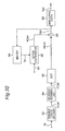
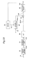
- the deblocking filter can be used as a post filter as shown in the block diagram of a video decoder using a conventional decoding method in Fig. 32 , or it can be used as an in-loop filter as shown in the block diagram of a video decoder using a conventional decoding method in Fig. 33 .
- the configurations shown in these block diagrams are described below.
- variable length decoder 52 variable length decodes encoded signal Str and outputs frequency code component DCoef.
- a de-zigzag scanning unit 54 rearranges the frequency components of the frequency code component DCoef in two-dimensional blocks, and outputs frequency component FCoef, the block unit frequency components.
- the reverse cosine transform unit 56 applies dequantization and reverse DCT operations to frequency component FCoef, and outputs difference image DifCoef.
- Motion compensator 60 outputs the pixel at the position indicated by externally input motion vector MV from the reference image Ref accumulated in memory 64 as motion compensated image MCpel.
- Adder 58 adds difference image DifCoef and motion compensated image MCpel to output reconstructed image Coef.
- Deblocking filter 62 applies coding distortion removal to reconstructed image Coef, and outputs decoded image signal Vout. Reconstructed image Coef is stored in memory 64, and used as reference image Ref for the next image decoding.
- the block diagram in Fig. 33 of a video decoder using a conventional decoding method is substantially identical to the block diagram of a video decoder shown in Fig. 32 , but differs in the location of the deblocking filter 62. As will be known from Fig. 33 the decoded image signal Vout output from deblocking filter 62 is stored to memory 64.
- the block diagram in Fig. 32 of a video decoder using a conventional decoding method shows the configuration and method used in MPEG-1, MPEG-2, MPEG-4, and H.263.
- the block diagram in Fig. 33 of a video decoder using a conventional decoding method shows the configuration and method used in H.261 and H.26L TM8.
- the reconstructed image Coef stored to memory 64 is not dependent upon the method applied by the deblocking filter 62.
- This allows developing and implementing various kinds of deblocking filters 62, including complex yet high performance filters as well as simple filters with relatively little effect according to the performance of the available hardware and the specific application.
- the advantage is that a deblocking filter 62 appropriate to the device can be used.
- the decoded image signal Vout stored to memory 64 is dependent upon the method employed by the deblocking filter 62.
- the problem here is that the filter cannot be changed to one appropriate to the hardware or application, but the advantage is that the same level of coding distortion removal can be assured in every device.
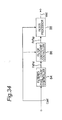
- Fig. 34 is a block diagram of a coding distortion removal unit using the conventional coding distortion removal method.
- Fig. 34 shows the configuration of the deblocking filter 62 in Fig. 32 and Fig. 33 in detail.
- the general concept behind coding distortion removal is to survey the image signal to determine the ratio of high frequency components in the image signal, identify high frequency components in image signal pixels normally thought to not contain a high frequency component as coding distortion, and apply a high frequency component suppression filter to the coding distortion. This is possible because the correlation between adjacent pixels in an image signal is high, pixels containing a high frequency component are concentrated in edge areas, and dispersed high frequency components can be considered to be coding distortion.
- This deblocking filter 62 was created by the inventors of the present invention based on content found in ITU-T Recommendation H.26L TML8.
- Filtered pixel count controller 84 uses reconstructed image Coef to determine the pixel positions containing coding distortion, and outputs filtered pixel count FtrPel.
- Filter coefficient controller 86 uses filtered pixel count FtrPel and reconstructed image Coef to determine the filter coefficient (including the number of filter taps) appropriate to removing coding distortion from the indicated pixels, and outputs filter coefficient FtrTap.
- the filter processor 88 applies filtering to remove coding distortion from reconstructed image Coef using the filter coefficient indicated by filter coefficient FtrTap, and outputs decoded image signal Vout.
- the conventional coding distortion removal methods described above are particularly effective at removing coding distortion, but the process is extremely complex and implementation difficult.
- a further problem is that the amount of data processed per unit time is high.
- An object of the present invention is therefore to provide a simple coding distortion removal method.
- a further object is to provide a coding distortion removal method, a coding method, and a decoding method whereby the likelihood of degrading image signal quality can be reduced by applying high performance coding distortion removal with less possibility of degrading image signal quality as a result of removing coding distortion than the prior art.
- a coding distortion removal method for removing coding distortion from a picture uses different methods to remove coding distortion at boundaries where the motion compensation unit boundary matches the coding unit boundary match, and boundary depending on whether the boundary is a motion compensation block boundary or not, when the motion compensation block size is larger than the coding block size.
- coding distortion at the boundary of the motion compensation unit differs qualitatively from coding distortion at the coding unit boundary
- coding distortion can be efficiently removed from an image signal containing coding distortion by changing the filter used for deblocking according to the unit.
- coding distortion is preferably removed only at the motion compensation block boundary.
- a further aspect of the invention is a coding distortion removal method for removing coding distortion from a picture by means of a step for extracting picture parameters from a picture containing coding distortion; a first step for identifying pixels for coding distortion removal using the picture parameters; a second step for identifying the method for coding distortion removal using the picture parameters; and a third step for removing coding distortion from the pixels identified by the first step using the coding distortion removal method identified by the second step.
- first computing picture parameters that can be used in both the first step identifying the pixels from which coding distortion is removed and the second step identifying the method used to remove the coding distortion
- the operations performed in the first step and second step can be simplified by using these common picture parameters, and processing by the coding distortion removal method can be reduced without degrading image quality.
- a further aspect of the invention is a coding distortion removal method for removing coding distortion from a picture whereby the pixels to be processed for coding distortion removal are identified by block based determination whether to remove coding distortion by block unit, and then pixel based determination whether to remove coding distortion for each pixel in the blocks determined to be removed by the block based determination.
- a yet further aspect of the invention is a coding distortion removal method for removing coding distortion in an area disposed on both sides of a block boundary between a first block and an adjacent second block in a picture having a plurality of blocks forming a moving picture image.
- This method has a comparison step for comparing a difference of pixel values of the first block and pixel values in pixels of the second block, and a parameter, corresponding to the average of a quantization parameter for the first block and a quantization parameter for the second block, for determining the method for removing coding distortion; and a removal step for removing coding distortion based on the result from the comparison step.
- Another coding distortion removal method for removing coding distortion in an area disposed on both sides of a boundary line between a first block and an adjacent second block in a picture having a plurality of blocks forming a moving picture image has a decoding step for decoding a parameter for setting a threshold value when removing coding distortion; a comparison step for comparing a difference of pixel values in pixels of the first block and pixel values in pixels of the second block, and a specific threshold value based on the decoded parameter; and a removal step for switching the method for removing coding distortion based on the result from the comparison step.
- Coding distortion can thus be efficiently removed from an image signal containing coding distortion by first superposing to each encoded signal a threshold value parameter used for coding distortion removal, and then prior to coding distortion removal detecting the threshold value appropriate to each encoded signal and using it to remove coding distortion.
- the moving picture contains a slice composed of plural blocks; and the parameter is stored in slice header information in a code stream obtained by encoding image data for the moving picture.
- a further aspect of the invention is a moving picture coding apparatus for picture coding with reference to at least one of multiple reference images, wherein a plurality of coded images obtained by removing coding distortion using plural methods are the reference images.
- the picture obtained by efficiently removing coding distortion from an image signal containing coding distortion can be used as the reference image, and the compression rate of moving picture coding can be increased.
- the first method of the plural methods is a method that does not remove coding distortion in the coded picture
- the second method is a method that removes coding distortion in the coded picture.
- a further aspect of the invention is a moving picture decoding apparatus for decoding with reference to at least one of multiple reference images, wherein a plurality of decoded images obtained by removing coding distortion using plural methods are the reference images.
- the picture obtained by efficiently removing coding distortion from an image signal containing coding distortion can be used as the reference image, and the coded signal can be corrected decoded.
- the first method of the plural methods is a method that does not remove coding distortion in the decoded picture
- the second method is a method that removes coding distortion in the decoded picture.
- a further aspect of the invention is a coding distortion removal method for removing coding distortion in an interlaced picture composed of odd-line pixels and even-line pixels.
- This method has an evaluation step for determining if a picture is a picture containing frame structure blocks having a specific number of odd-line pixels and a specific number of even-line pixels, a picture containing blocks of one field structure composed of a specific number of odd-line pixels, or a picture containing blocks of another field structure composed of a specific number of even-line pixels; and a removal step for removing coding distortion between adjacent frame structure blocks when the target block for coding distortion removal is a block in a picture in which all blocks are frame structure blocks, and removing coding distortion between adjacent field structure blocks when the target block for coding distortion removal is a block in a picture in which all blocks are field structure blocks.
- Processing of the blocks for coding distortion removal can thus be changed based on whether the blocks are in a picture of frame structure blocks or a picture of field structure blocks.
- the coding distortion removal method also has a conversion step for converting a field structure block to a frame structure block; a comparison step for comparing a difference of pixel values in pixels of the field structure block and pixel values in pixels of the converted block with a specific threshold value; and a removal step for removing coding distortion based on the result from the comparison step.
- the first blocks are frame structure blocks having a specific number of odd-line pixels and a specific number of even-line pixels in an interlaced picture composed of odd-line pixels and even-line pixels
- the second blocks are field structure blocks having one field composed of a specific number of odd-line pixels in an interlaced picture composed of odd-line pixels and even-line pixels, and another field composed of a specific number of even-line pixels in an interlaced picture composed of odd-line pixels and even-line pixels.
- the coding distortion removal method has a conversion step for converting a frame structure first block to a field structure block; a comparison step for comparing a difference of pixel values in pixels of the field structure second block and pixel values in pixels of the converted block with a specific threshold value; and a removal step for removing coding distortion based on the result from the comparison step.
- the target blocks for coding distortion removal can thus be adaptively processed.
- conversion from frame structure first blocks to field structure blocks switches by macroblock unit or units of two vertically adjacent macroblocks.
- field structure second blocks are not converted to frame structure blocks.
- the first blocks are frame structure blocks having a specific number of odd-line pixels and a specific number of even-line pixels in an interlaced picture composed of odd-line pixels and even-line pixels
- the second blocks are field structure blocks having one field composed of a specific number of odd-line pixels in an interlaced picture composed of odd-like pixels and even-line pixels, and another field composed of a specific number of even-line pixels in an interlaced picture composed of odd-line pixels and even-line pixels.
- the coding distortion removal method has an evaluation step for determining if the target block for coding distortion removal is a frame structure block or a field structure block; a conversion step for converting the frame structure first block to a field structure block when the target block is a field structure second block, and converting the field structure second block to a frame structure block when the target block is a frame structure first block; a comparison step for comparing pixel values in pixels of the target block with a specific threshold value; and a removal step for removing coding distortion based on the result from the comparison step.
- the target blocks for coding distortion removal can thus be adaptively processed.
- conversion in the conversion step from a frame structure block to a field structure block produces one field after conversion from odd-line pixels in the frame structure block, and produces the other field after conversion from even-line pixels in the frame structure block; and comparison of the difference and threshold value in the comparison step compares pixel values in pixels in one field of the second block and pixel values in pixels in one field of the first block after conversion, or compares pixel values in pixels of the other field in the second block and pixel values in pixels of the other field in the first block after conversion.
- the first blocks are frame structure blocks having a specific number of odd-line pixels and a specific number of even-line pixels in an interlaced picture composed of odd-line pixels and even-line pixels
- the second blocks are field structure blocks having one field composed of a specific number of odd-line pixels in an interlaced picture composed of odd-line pixels and even-line pixels, and another field composed of a specific number of even-line pixels in an interlaced picture composed of odd-line pixels and even-line pixels.
- the coding distortion removal method has a conversion step for converting a field structure second block to a frame structure block; a comparison step for comparing a difference of pixel values in pixels of the frame structure first block and pixel values in pixels of the converted block with a specific threshold value; and a removal step for removing coding distortion based on the result from the comparison step.
- the target blocks for coding distortion removal can thus be adaptively processed.
- conversion from field structure second blocks to frame structure blocks switches by macroblock unit or units of two vertically adjacent macroblocks.
- field structure second blocks are not converted to frame structure blocks.
- conversion in the conversion step from field structure block to frame structure block produces a converted frame from pixels in a block of one field and pixels in a block of the other field, and compares pixel values in odd-line pixels in the first block with pixel values in odd-line pixels in the second block after conversion, or compares pixel values in even-line pixels in the first block with pixel values in even-line pixels in the second block after conversion.
- the comparison step compares the difference and threshold value by groups of plural pixels aligned in line in a same direction as the boundary line at positions symmetrical to the boundary line.
- a yet further aspect of the present invention is a picture coding apparatus having a decoding unit for decoding a coded difference picture and outputting the difference picture; a motion compensation unit for outputting a motion compensated picture from a reference image; an adder for adding the difference picture and motion compensated picture, and outputting the merged picture; a coding distortion removal unit for removing coding distortion in the merged picture and outputting a reconstructed picture; and memory for storing the reconstructed picture as the reference image.
- the coding distortion removal unit removes coding distortion by means of any of the above-described methods of the invention.
- a yet further aspect of the invention is a program for removing coding distortion from a picture by means of any of the above-described methods of the invention.
- a yet further aspect of the invention is a program for picture coding using a decoding unit for decoding a coded difference picture and outputting the difference picture; a motion compensation unit for outputting a motion compensated picture from a reference image; an adder for adding the difference picture and motion compensated picture, and outputting the merged picture; a coding distortion removal unit for removing coding distortion in the merged picture and outputting a reconstructed picture; and memory for storing the reconstructed picture as the reference image.
- the coding distortion removal unit removes coding distortion by means of any of the above-described methods of the invention.
- variable length decoder 52 variable length decodes encoded signal Str and outputs frequency code component DCoef.
- De-zigzag scanning unit 54 rearranges the frequency components of the frequency code component DCoef in two-dimensional blocks, and outputs frequency component FCoef, the block unit frequency components.
- the reverse cosine transform unit 56 applies dequantization and reverse DCT operations to frequency component FCoef, and outputs difference image DifCoef.
- Motion compensator 60 outputs the pixel at the position indicated by externally input motion vector MV from the reference image Ref accumulated in memory 64 as motion compensated image MCpel, and outputs motion compensation block size MCsize denoting the size of the motion compensation block.
- Adder 58 adds difference image DifCoef and motion compensated image MCpel to output reconstructed image Coef.
- Deblocking filter 62 receives reconstructed image Coef, motion compensation block size MCsize, and difference image DifCoef, applies coding distortion removal, and outputs decoded image signal Vout.
- Reconstructed image Coef is stored in memory 64, and used as reference image Ref for the next image decoding.
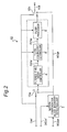
- Fig. 2 is a block diagram of deblocking filter 62 (also called a coding distortion removal unit) using a coding distortion removal method according to the present invention.
- This deblocking filter 62 was created by the inventors of the present invention with reference to the content of a deblocking filter described in ITU-T Recommendation H.26L TML8.
- Filtered pixel count controller 4 determines the pixel positions containing coding distortion for each reconstructed image Coef, and outputs filtered pixel count FtrPel. Filtered pixel count FtrPel thus indicates the pixel position that needs filtering.
- Filter coefficient controller 6 uses filtered pixel count FtrPel and reconstructed image Coef to determine the filter coefficient (including the number of filter taps) appropriate to removing coding distortion from the indicated pixels, and outputs filter coefficient FtrTap.
- the filter processor 8 applies a filter process to remove coding distortion from reconstructed image Coef using the filter coefficient indicated by filter coefficient FtrTap, and outputs decoded image signal Vout.
- the difference image DifCoef and motion compensation block size MCsize are input to motion compensation block boundary detection unit 2, which determines whether the difference image DifCoef for the process block is less than or equal to a specific value, such as whether it is 0, detects the boundaries of the motion compensation block, and outputs motion compensation block boundary flag IsEdge.
- Fig. 3 shows examples of the motion compensation block size used in ITU-T Recommendation H.26L TML8.
- the maximum motion compensation block size is 16 x 16 pixels, the same size as what is referred to as a macroblock.
- the motion compensation block sizes shown in Fig. 3 (a) to (g) are 4x4, 4x8, 8x4, 8x8, 8x16, 16x8, and 16x16 pixels.
- the size appropriate to the macroblock unit is selected from these seven motion compensation block sizes and used for coding and decoding. It should be noted that coding and decoding can be applied to an appropriate unit of two vertically adjacent macroblocks, and a unit of such macroblocks is called a "macroblock pair.”
- the unit used for frequency transforms and coding in ITU-T Recommendation H.26L TML8 is 4x4 pixels.
- This unit of 4x4 pixels is called a "coding unit.”
- each of the sixteen blocks A to P is a 4x4 pixel block.
- the 4x4 pixel coding unit matches the motion compensation block size only in the case shown in Fig. 3 (a) . Because block distortion that is particularly visually disruptive as coding distortion occurs at the smallest coding unit size of 4x4 pixels, the conventional coding distortion removal method always works on 4x4 pixel units.
- the coded motion compensation error between pictures is 0. Because the difference image DifCoef coded and decoded in 4x4 pixel units is also 0 in this case, discontinuities in the pixel values resulting from coding distortion during coding and decoding likely does not occur in places other than the boundaries of the motion compensation blocks. Therefore, if the motion compensation blocks are selected as shown in Fig. 3 (b) , the coding distortion removal process is not needed at the 4x4 pixel unit boundaries indicated by the dotted lines between blocks AC, BD, EG, FH, IK, JL, MO, and NP shown in Fig. 3 (a) .
- Deblocking is likewise not needed at the 4x4 pixel unit boundaries indicated by the dotted lines between blocks AB, CD, EF, GH, IJ, KL, MN, and OP shown in Fig. 3 (a) . If difference image DifCoef used for coding/decoding in 4x4 pixel units is also 0, deblocking is applied only at the boundaries of the motion compensation blocks, and is not applied at the boundaries of the 4x4 pixel units within the motion compensation blocks. This makes it possible to reduce the number of operations in the coding distortion removal process compared with deblocking all block boundaries.
- motion compensation block boundary detection unit 2 sets both selectors 10a and 10b off (indicated by a solid line) and selector 10b outputs reconstructed image Coef as decoded image signal Vout.
- the selectors 10a and 10b are switched by setting the motion compensation block boundary flag IsEdge. Processing by filtered pixel count controller 4, filter coefficient controller 6, and filter processor 8 can thus be omitted by switching selectors 10a and 10b off.
- selectors 10a and 10b are ON (denoted by the dotted line), and the output from filter processor 8 is output from selector 10b as decoded image signal Vout.
- This selector state is also set by applying motion compensation block boundary flag IsEdge.
- the present invention thus introduces the ability to omit operation of filtered pixel count controller 4, filter coefficient controller 6, and filter processor 8 by applying an appropriately set motion compensation block boundary flag IsEdge, and by skipping these units enables faster processing and reduces power consumption by these processes.
- this embodiment is described as simply not applying any coding distortion removal process, a simple coding distortion removal process could be used instead of skipping the process altogether, and switching could be between a complex coding distortion removal process and coding distortion removal processing in 4x4 pixel units.
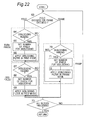
- step S18 It is first determined in step S18 whether the target block is a coding distortion removal block. If it is, control advances to step S19. If it is not, control advances to step S24.
- step S19 An appropriate coding distortion removal filter is selected in step S19, coding distortion removal processing is applied using the selected filter in step S20, and the target pixel is changed to the next unprocessed pixel in the block in step S21. If there are no unprocessed pixels in the block (step S22 returns no), control advances to step S24. If there is an unprocessed pixel (step S22 returns yes), control loops back to step S19 and the process repeats.
- Step S24 detects if there is another unprocessed block in the picture. If there is, control advances to step S23. If all blocks have been processed (step S24 returns no), the coding distortion removal process ends for that picture.
- step S23 If unprocessed blocks remain, the target block is changed to the next unprocessed block in step S23, control loops back to step S18 and the process repeats.
- Fig. 6 is a flow chart showing how the number of pixels to filter (the "filtered pixel count” below) is determined in the coding distortion removal method of the present invention.
- This flow chart describes one example the filtered pixel count controller 4 shown in Fig. 2 could operate.
- Fig. 6 shows a case in which the motion compensation block is the one shown in Fig. 8 (a) .
- the target pixel values for coding distortion removal are p3, p2, p1, p0, q0, q1, q2, q3 as shown in Fig. 8 (b)
- the pixel values after coding distortion removal are P3, P2, P1, P0, Q0, Q1, Q2, Q3.
- pixel values are assigned sequentially in the same order as the pixel positions, p0 to p3 and P0 to P3 denote corresponding pixels in the same block, and q0 to q3 and Q0 to Q3 denote corresponding pixels in the same block.
- Fig. 5 is a table showing the correlation between quantization parameter QP and coding distortion removal parameters.
- the correlation between parameters ⁇ , ⁇ , and n of the deblocking process for determining parameter n denoting the filtered pixel count is shown in Table 1 below. It should be noted that filtering should not be applied if the pixel difference is large because this denotes an edge, and ⁇ is therefore preferably set so that filtering is not applied to pixels where the pixel difference is less than ⁇ .
- ⁇ is therefore preferably set so that a stronger filter (i.e., n is high) is applied based on whether the pixel difference is extremely low (less than ⁇ ) or somewhat small (less than 2x ⁇ ).
- Step S27 computes pixel difference DifPel, a parameter that is repeatedly computed in the coding distortion removal process. Note that pixel difference DifPel refers to dif1a and dif2a calculated in step S27.
- dif2 is the absolute value of the difference in pixel values in proximity to the boundary, and because the number of high frequency components near the boundary decreases as this difference decreases, coding distortion can be removed efficiently from the boundary area by increasing the number of pixels processed for deblocking as dif2 gets smaller.
- Fig. 7 is a flow chart of a process for determining the filter coefficient in the coding distortion removal method of the present invention, and is an example of the operation of filter coefficient controller 6 in Fig. 2 .
- n is the threshold value for determining the number of filter taps
- a three tap filter normally provides stronger suppression of high frequency components than a single tap filter. Because the filter process can be changed using the value of n, parameter n can be used to change the type of filter instead of the number of pixels the filter is applied to. Parameter n thus obtained can also be used to change both the number of pixels filtered and the type of filter applied.
- quantization parameter QP can be changed for each block.
- the coding distortion removal process becomes more complicated at the boundary between blocks having a different quantization parameter QP.
- the present invention prevents this by using:
- Coding distortion can thus be easily removed by the method described above.
- Fig. 8 (a) is a block diagram of another embodiment of the deblocking filter 62 shown in Fig. 1 , and a separate embodiment of the part enclosed in a dotted line in Fig. 2 . It should be noted that like parts in Fig. 8 and the block diagram of the coding distortion removal unit using the conventional coding distortion removal method shown in Fig. 34 are identified by like reference numerals, and further description thereof is omitted here.
- the pixel difference calculator 20 computes the pixel difference at the block boundary from reconstructed image Coef, and outputs pixel difference DifPel.
- This pixel difference DifPel contains a signal equivalent to dif1 a and dif2a.
- Pixel difference DifPel is obtained by comparing pixels at symmetrical positions left and right or above and below the boundary between coding unit blocks, and using the difference d1, d2, d3, d4 (color difference or luminance difference) therebetween.
- the flow chart for determining the filtered pixel count can be used as an example of filtered pixel count controller 4 operation.
- An example of filter coefficient controller 6 operation in this embodiment is shown in the flow chart for determining the filter coefficient shown in Fig. 7 .
- the number of pixel difference calculations can be reduced for both filtered pixel count controller 4 and filter coefficient controller 6.
- the filtered pixel count controller 4 and filter coefficient controller 6 can therefore set the filtered pixel count and filter coefficient without referencing reconstructed image Coef.
- This embodiment of the invention describes an encoding apparatus and a decoding apparatus implementing the coding distortion removal method described in another embodiment of the invention.
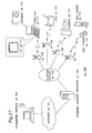
- Fig. 9 is a block diagram of the encoding apparatus.
- Motion detection unit 30 compares reference image Ref1 and reference image Ref2 output respectively from first memory 38 and second memory 40 with image signal Vin, and detects motion vector MV, that is, the amount of motion in image signal Vin relative to the reference image. It should be noted that information indicating whether prediction error will be less by referencing reference image Ref1 or reference image Ref2 is also included in the motion vector MV and reported to motion compensation unit 32.
- the motion compensation unit 32 extracts the image at the position indicated by motion vector MV from reference image Ref1 or reference image Ref2, and outputs it as motion compensated image MCpel.
- Subtracter 42 obtains the difference of image signal Vin and motion compensated image MCpel, and outputs to cosine transform unit (DCT) 46.
- Cosine transform unit 46 computes the DCT and quantizes the input difference, and outputs frequency component FCoef.
- Zigzag scanner 48 outputs frequency code component DCoef reordering the sequence of frequency component FCoef, and variable length coding unit 50 variable length codes frequency code component DCoef to output encoded signal Str.
- the output of the DCT unit (cosine transform unit) 46 is also input to inverse DCT unit (reverse cosine transform unit) 44.
- Frequency component FCoef and motion compensated image MCpel output from motion compensation unit 32 are merged by synthesizer 34, and merged image Coef is output.
- the merged image Coef is stored as is to first memory 38, and is also processed by deblocking filter 36 and the decoded image signal Vout from which coding distortion has been removed is stored to second memory 40.
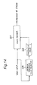
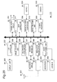
- Fig. 10 is a block diagram of the decoding apparatus. This decoding apparatus correctly decodes the encoded signal Str encoded by the encoding apparatus shown in the block diagram in Fig. 9 . Parts in Fig. 10 that operate the same as the corresponding parts in Fig. 32 or Fig. 33 are identified by like reference numeral, and further thereof description is omitted here.
- the inverse DCT unit (reverse cosine transform unit) 56 dequantizes frequency component FCoef and computes the inverse DCT to output difference image DifCoef.
- the adder 58 adds difference image DifCoef and motion compensated image MCpel to obtain reconstructed image Coef. Reconstructed image Coef is stored to first memory 64, and decoded image signal Vout obtained by deblocking filter 62 removing coding distortion from reconstructed image Coef is stored to second memory 66.
- the encoding apparatus shown in Fig. 9 is therefore configured so that the motion detection unit 30 can always select the best output from both first memory 38 and second memory 40.
- an appropriate reference image can be selected by referencing first memory 38.
- An appropriate reference image can likewise be selected by the decoding apparatus shown in Fig. 10 .
- DCT is used as the orthogonal transform in this embodiment of the invention, but a Hadamard transform or wavelet transform could be used.
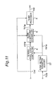
- Fig. 11 is a block diagram of a coding distortion removal unit according to a preferred embodiment of the invention, and corresponds to the deblocking filter 62 shown in Fig. 1 , for example.
- This coding distortion removal unit is distinguished by determining the threshold value for setting the filter. It should be noted that parts performing the same operation as like parts in the coding distortion removal unit shown in Fig. 34 are identified by like reference numerals and further description thereof is omitted here.
- Filter setting parameter decoder 22 decodes filter setting parameter signal FtrStr, and outputs filter parameter FtrPrm.
- This filter setting parameter signal FtrStr is not a threshold value, but is a parameter for setting the threshold value.
- Filter parameter FtrPrm is equivalent to ⁇ , Q, and ⁇ in Fig. 5 .
- Fig. 12 shows the structure of encoded signal Str in the coding distortion removal method of the present invention.
- Fig. 12 (a) is an encoded signal for one picture, and contains picture data PicData holding the data for one picture, and picture header PicHdr common to all data in one picture. This picture header PicHdr contains the filter setting parameter signal FtrStr.
- Fig. 12 (b) shows the structure of picture data PicData.
- This picture data PicData contains slice signal SliceStr, the encoded signal of a slice containing a group of plural block units.
- Fig. 12 (c) shows the structure of slice signal SliceStr, which contains slice data SliceData holding the data for one slice, and slice header SliceHdr common to all data in the one slice.
- filter setting parameter signal FtrStr could be written to only some of the slice headers SliceHdr instead of writing filter setting parameter signal FtrStr to all slice headers SliceHdr. If the content of the filter setting parameter signal FtrStr is common to each slice, and filter setting parameter signal FtrStr is not written to the slice header SliceHdr as shown in Fig. 12 (c) , an increase in the number of bits due to repeating the filter setting parameter signal FtrStr can be suppressed by substituting filter setting parameter signal FtrStr from another slice header SliceHdr.
- the header and non-header parts can be separately transmitted. In this case the header and data parts will not be in a single bit stream as shown in Fig. 12 . However, even if the transmission sequence of the header and data parts is not continuous, the header for a particular data packet is simply transmitted in another packet, and the concept is the same as the bit stream shown in Fig. 12 even though the transmission is not a single bit stream.
- Fig. 13 is a block diagram of the encoding apparatus. Note that like parts in Fig. 13 and Fig. 9 are identified by like reference numerals and further description thereof is omitted here.
- Memory 217 stores image signal Vin, that is, the image signal input for encoding.
- Image quality comparison unit 216 compares the encoding target image signal read from memory 217 with decoded image signal Vout. The size of the error obtained from the comparison done by image quality comparison unit 216 is stored together with the deblocking filter threshold value for the decoded image to comparison memory 218.
- the selection unit 219 selects as the optimum threshold value the threshold value of the deblocking filter corresponding to the smallest error stored in comparison memory 218. The selected optimum threshold value is multiplexed as a related added bit stream to the bit stream of the corresponding picture.
- threshold value control unit 215 Based on the optimum threshold value output by selection unit 219, threshold value control unit 215 generates a candidate threshold value for the deblocking filter of the next picture, advises the deblocking filter 36 and changes the threshold value of the coding distortion removal process, and sends the threshold value currently in use to the comparison memory 218.
- Fig. 14 is a conceptual representation of the specific encoding apparatus shown in the block diagram in Fig. 13 .
- the optimum threshold value selection unit 226 performs the operations of the parts in Fig. 13 other than zigzag scanner 48, variable length coding unit 50, and threshold value appending unit 220, equivalent to the operation of memory 217, image quality comparison unit 216, comparison memory 218, selection unit 219, and threshold value control unit 215.
- the video encoder 227 corresponds to the operation of the parts other than the memory 217, image quality comparison unit 216, comparison memory 218, selection unit 219, and threshold value control unit 215 in Fig. 13 .
- Threshold value 228 is equivalent to the above optimum threshold value.
- the optimum threshold value selection unit 226 selects an optimum threshold value. This optimum threshold value is equivalent to the set of ⁇ , ⁇ , and ⁇ values determined for each quantization parameter QP in Fig. 5 .
- the selected optimum threshold value is stored to threshold value memory 228 and applied to video encoder 227 as filter setting parameter signal FtrStr.
- the encoded filter setting parameter signal FtrStr is processed by the filter setting parameter decoder 22 shown in Fig. 11 , for example, in the decoder.
- threshold value control unit 215 shown in Fig. 13
- threshold value data sent by threshold value control unit 215 to threshold value appending unit 220.
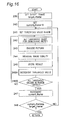
- FIG. 15 , Fig. 16 , and Fig. 17 are flow charts showing the operation of the encoding apparatus described with Fig. 13 and Fig. 14 .
- Fig. 15 is a flow chart of an operation for measuring image quality.
- the target frame target_frame is first set and the first picture output (step 229).
- the target frame target_frame is the picture used for deriving the threshold value.
- the threshold value control unit 215 sets a threshold value range (step 230), and the value at one end of this range is output from threshold value control unit 215 as the initial threshold value (step 231).
- the deblocking filter 36 removes coding distortion, begins coding the picture for target frame target_frame (step 232), and image quality comparison unit 216 then measures the image quality of this first encoded picture and image signal Vin (step 233).
- step 234 The result of this comparison is stored to comparison memory 218 (step 234), and the current frame number current_frame is incremented (step 235). That is, the picture being processed is changed from the first picture to the next picture, and the next picture is output to, for example, optimum threshold value selection unit 226 and video encoder 227 shown in Fig. 14 or memory 217, motion detection unit 30, and subtracter 42 shown in Fig. 13 .
- Step 236 determines if the current frame number current_frame has reached the target frame target_frame. If it has not, steps 233 to 235 repeat. The image quality of the input picture is measured by image quality comparison unit 216, and the result is stored to comparison memory 218. If the current frame number current_frame equals the target frame target_frame, control advances to step 237 and the current frame number current_frame is reset to the first picture.
- the threshold value control unit 215 then increments the threshold value (step 238A), that is, the threshold value is set to the next value. This "next value” is the value increased a specific increment from the first value.
- step 238B Whether all threshold values to the threshold value at the other end of the set range have been tested is then determined. If all threshold values have been tested, the process for determining the optimum threshold value ends. If all threshold values have not been tested, control loops back to step 232 and the picture for target frame target_frame is encoded.
- Image quality can thus be measured by measuring the image quality for all target frames target_frame using one threshold value, then incrementing the threshold value a specific amount, and then again measuring image quality for all target frames target_frame.
- the target frame target_frame is first set and the first picture output (step 239).
- the current frame number current_frame is then initialized to 0 (step 240).
- the threshold value control unit 215 then sets a threshold value range (step 241), and the threshold value is set to the deblocking filter 36 (step 242).
- the first picture is then encoded (processed for coding distortion removal) using the initial threshold value (step 243), and the image quality of the encoded picture is measured by image quality comparison unit 216 (step 244).
- image quality comparison unit 216 is stored to comparison memory 218 (step 245), and the threshold value control unit 215 increments the threshold value to the next value (step 246A).
- step 246B Whether all threshold values have been tested is then determined (step 246B). If all threshold values have not been tested, control loops back to step 242 and the image quality of the same picture is measured using a different threshold value. If all threshold values have been tested, control advances to step 247.
- the current frame number current_frame is then incremented in step 247. That is, the picture being processed is changed from the first picture (the first frame) to the second picture (the second frame), and the next picture is output to, for example, optimum threshold value selection unit 226 and video encoder 227 shown in Fig. 14 or memory 217, motion detection unit 30, and subtracter 42 shown in Fig. 13 .
- Step 248 determines if the current frame number current_frame has reached the target frame target_frame. If it has not, steps 241 to 247 repeat. If current_frame equals target_frame, the image quality measurement process ends.
- Fig. 17 is a flow chart of a method for selecting the optimum threshold value based on the threshold value described in Fig. 15 or Fig. 16 and the results of measuring image quality at that threshold value.
- the selection unit 219 gets the image quality measurement results and corresponding threshold value data in step 249 in Fig. 17 .
- the measurement results are then arranged in a specific order (step 250).
- the picture with the best image quality is then selected based on specific conditions (step 251), and the threshold value for that picture is selected as the optimum threshold value.
- These specific conditions could be any one of or a combination of the following: a low S/N ratio, the smallest difference between the reconstructed image (the picture deblocked at the threshold value) and the original picture (input image signal Vin), and the lowest mean square of the difference.
- the selected optimum threshold value is then output as filter setting parameter signal FtrStr to, for example, video encoder 227 in Fig. 14 (step 252).
- the best threshold value can thus be selected using the method described with reference to Fig. 17 .
- this preferred embodiment measures image quality for all threshold values in a specified range, gathers the image quality measurement results, and selects the optimum threshold value from among the results. It is also possible to measure image quality in sequence for all threshold values in a threshold value range, end image quality measurement at the point a result with the best image quality is detected, and select the threshold value producing that image quality result as the optimum threshold value. This method can reduce the number of image quality measurements performed.
- the coding distortion removal process for a given block compares the pixel values in that block with the pixel values in an adjacent block.
- the adjacent block in this case is a block for which the coding distortion removal process has ended and pixel value correction has ended.
- coding distortion could be removed by comparison with any of the four adjacent blocks E, D, H, and M.
- coding distortion can be removed more accurately.
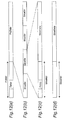
- Coding distortion is preferably removed in linear sequence in the scanning order. That is, coding distortion is removed in the scanning direction of the horizontal scan lines of the picture in horizontal scan line sequence.
- the first scan line of blocks A, B, E, F is processed first for coding distortion removal, then the next line of blocks C, D, G, H is processed, and so forth.
- Each block has four boundaries, but coding distortion removal processing is preferably applied using the adjacent blocks touching the top boundary and left boundary.
- coding distortion removal processing is not applied to block A because there is an adjacent block touching its top boundary or left boundary.
- Blocks E and D are respectively adjacent to the top and left boundaries of block G, and coding distortion is therefore removed from block G using blocks E and D while not using blocks H and M.
- coding distortion By thus removing coding distortion between a new block and adjacent blocks from which coding distortion has already been removed, and not referencing adjacent blocks that have not been processed for coding distortion, coding distortion can be removed more accurately.
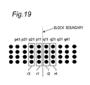
- This embodiment first describes a case in which pixels are divided into groups of multiple pixels each, such as groups of four pixels in one column, groups are then paired, and coding distortion removal is applied to group pairs.
- a coding distortion removal process as used in this embodiment refers to both or either determining whether to apply deblocking to an area on both sides of a block boundary, and the deblocking operation itself.
- a block could be a 4x4 block of 16 pixels that is the smallest coding unit, or any of the blocks to which motion compensation is applied as described above with reference to Fig. 3 .
- the four pixels in one group are a group of four pixels arranged in line with the block boundary.
- Four such groups are shown in Fig. 19 , r1, r2, r3, and r4.
- Data from these four groups r1, r2, r3, and r4 can be stored to four registers (SIMD registers, for example).
- Groups r1, r2 and groups r3, r4 are symmetrically located on left and right sides of the block boundary. Pixel values in group r1 are compared with pixel values in group r2, and coding distortion removal processing is applied using the resulting differences.
- difference 1 between the top pixel in group r1 and the top pixel in group r2 difference 2 between the second to the top pixel in group r1 and the second to the top pixel in group r2, difference 3 between the second to bottom pixel in group r1 and the second to bottom pixel in group r2, and difference 4 between the bottom pixel in group r1 and the bottom pixel in group r2 are obtained.
- the average of difference 1, difference 2, difference 3, and difference 4, or the sum of the absolute values of difference 1, difference 2, difference 3, and difference 4, is used as a representative difference, and this representative difference is compared with a specific threshold value. Other methods are also possible. Because these operations are performed on units of four pixels in the same groups, parallel processing can be used for significantly faster throughput compared with processing each pixel at a time.
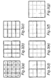
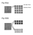
- Fig. 20 (a) and (b) show cases in which the scan lines are interlaced on screen.
- An interlaced picture is a picture in which one frame consists of two fields presented at different times. Coding and decoding an interlaced picture can be accomplished by processing one frame as a frame, as two fields, or by frame structure or field structure blocks in one frame.
- the small gray squares denote odd-line pixels
- the small white squares denote even-line pixels.
- the gray pixels of the odd lines thus form one field of a frame and the white pixels on the even lines form the other field of the same frame.
- one frame consists of two fields (an even field and an odd field) at different time instants.
- the pixel values do not change with time, and the correlation between vertically adjacent lines in a frame is stronger than the correlation between vertically adjacent lines in a field.
- the picture changes greatly with time pixel values can thus differ greatly in two fields, and the correlation between vertically adjacent lines in a field is stronger than the correlation between vertically adjacent lines in a frame. It is therefore more efficient to process still pictures by frame and moving pictures by field.
- all blocks could be frame structure blocks (the frame structure is described further below), (2) all blocks could be field structure blocks (the field structure is described further below), or (3) the picture could contain both frame structure and field structure blocks.
- Fig. 20 (a) Interlaced pictures that are still images or contain little motion are processed by frame units consisting of odd fields and even fields as shown in Fig. 20 (a) (referred to herein as a "frame structure").
- a frame structure As shown on the right side in Fig. 20 (a) , a block of 16 pixels contains both odd-line pixels and even-line pixels.
- the coding distortion removal process is applied between blocks with a frame structure. That is, as described with reference to Fig. 8 (b) , coding distortion removal processing is applied to the block boundaries.
- Fig. 20 (b) Interlaced pictures with much motion are processed by field unit separated into odd fields and even fields as shown in Fig. 20 (b) (referred to herein as a "field structure"). As shown on the right side in Fig. 20 (b) , the picture is separated into odd fields of odd-lines and even fields of even-lines; odd fields contain blocks of odd-lines, and even fields contain blocks of even-lines.
- the coding distortion removal process is applied only between field structure blocks of only odd-lines or field structure blocks of only even-lines.
- Fig. 21 (a) shows a case in which part of the interlaced image consists of frame structure blocks and another part consists of field structure blocks.
- the moving picture part of the image contains the field structure blocks and the still picture part contains the frame structure blocks.
- the smallest unit formed by a field structure or frame structure is the macroblock, i.e., the largest unit to which DCT or other orthogonal transform or motion compensation is applied (or super-macroblocks of plural macroblocks). It is assumed below that the rectangle containing the car in Fig. 21 (a) contains field structure blocks, and the rest of the picture contains frame structure blocks.
- the blocks in columns G1, C2, C3, and C4 belong to the image area containing the car and thus have a field structure because of the motion in this image area.
- the blocks in columns C5, C6, C7, and C8 belong to the area where the car is not, that is, the still picture area, and thus have an efficient frame structure.
- the macroblocks have 16 pixels per side and the blocks have 4 pixels per side.
- Columns C4 and C5 are shown apart in Fig. 21 (b) but are actually adjacent in the picture. Coding distortion removal as shown in Fig. 8 (b) is applied to the block boundary between columns C3 and C4 and the block boundary between columns C5 and C6.
- the frame structure blocks in column C5 are first converted to field structure blocks as shown in Fig. 21 (c) . This is done by, for example, converting the odd-line pixels in column C5 shown in Fig. 21 (b) to a block of gray pixels in column C5 as shown in Fig. 21 (c) , and converting the even-line pixels in column C5 shown in Fig. 21 (b) to a block of white pixels in column C5 as shown in Fig. 21 (c) . Coding distortion at the block boundary between columns C4 and C5 is then removed as shown in Fig. 8 (b) .
- Frame structure blocks are thus converted to field structure blocks because the vertical correlation between pixels will be lost if field structure blocks are converted to frame structure blocks when there is movement in the picture, and unnatural degradation occurs if the coding distortion removal process is applied between vertically adjacent blocks.
- the vertical correlation between pixels is not lost and unnatural image quality degradation does not occur easily.
- Frame structure blocks are converted to field structure blocks to reduce the amount of processing (only converting frames to fields) in the above example.
- an alternative method can be used that converts frames to fields and field to frames, and thus increases the number of operations compared with the previous example because of the additional processing required to convert fields to frames. More specifically, whether the target pixels for coding distortion removal (i.e., the current pixel for which the pixel value is to be changed by deblocking) are in a frame structure block or a field structure block is first determined.
- frame structure blocks are converted to field structure blocks (i.e., the block type of the target pixel)
- field structure blocks are converted to frame structure blocks (i.e., the block type of the target pixel).
- a frame in an interlaced image signal stream consists of two fields scanned at different time instants.
- a frame can therefore be frame encoded by combining the two fields into a single coding unit (frame structure coding), or it can be field encoded with the two fields coded and handled separately (field structure coding).
- frame structure coding coding unit
- field structure coding field structure coding
- These coding methods can also be grouped into the following two categories, fixed coding and adaptive coding. With fixed coding the entire picture is switched between either frame coding or field coding. With adaptive coding the picture is divided into a number of blocks and each block is either frame encoded or field encoded.
- Fixed coding further includes frame-fixed coding applied to frame structure blocks, and field-fixed coding applied to field structure blocks. With fixed coding the interlaced video sequence is always encoded with either frame encoding or field encoding regardless of the content.
- frame encoding or field encoding can be adaptively selected based on the content, the picture, or coding block unit in the picture.
- These in-picture coding blocks can be as small as the macroblock.
- adaptive coding individual macroblocks can therefore be coded using either frame encoding or field encoding. Macroblocks are used as the coding unit below.
- Frame encoded blocks that is, blocks with a frame structure, can be processed for coding distortion removal using the same technique applied to non-interlaced video.
- field encoded blocks that is, blocks with a field structure
- the fields are separated into even fields and odd fields, each field is handled as a separate picture, and deblocking is therefore applied to each field.
- step 63 whether the target block is field encoded or frame encoded is decided. If the block is field encoded, steps 64 to 69 are run. If the block is frame encoded, steps 70 to 72 run.
- Steps 64 to 66 process even field structure blocks, and steps 67 to 69 process odd field structure blocks. Steps 64 to 66 remove coding distortion between white pixels at the boundary between columns C3 and C4 in Fig. 21 (b) , and steps 67 to 69 remove coding distortion between gray pixels at the boundary between columns C3 and C4 in Fig. 21 (b) .
- step 64 pixel luminance is compared in step 64 to determine whether coding distortion removal is needed.
- the number of pixels to be filtered is then determined in step 65. Coding distortion is then removed in the field mode in step 66.
- Steps 67, 68, and 69 perform the same operations as steps 64, 65, and 66, respectively.
- Steps 70 to 72 process frame structure blocks to remove coding distortion at the boundary between columns C5 and C6 in Fig. 21 (b) . More specifically, pixel luminance is compared in step 70 to determine whether coding distortion removal is needed. The number of pixels to be filtered is then determined in step 71. Coding distortion is then removed in the frame mode in step 72.
- step 73 Whether all blocks have been processed is determined in step 73, and if they have operation ends.
- Fig. 23 shows an alternative method in which steps 64 and 67 in Fig. 22 are combined into a single step. More specifically, whether it is necessary to remove coding distortion from both even field blocks and odd field blocks is determined, and deblocking is applied to both even and odd field blocks if it is needed. This simplifies the coding distortion removal process.
- Fig. 24 shows a further alternative method in which steps 65 and 68 in Fig. 23 are combined into a single operation determining the number of pixels in both the even field blocks and odd field blocks to be deblocked. Coding distortion removal is then applied to both even and odd field blocks based on the result. This method further simplifies coding distortion removal.
- Fig. 25 is a flow chart of a process used when frame encoded blocks and field encoded blocks are mixed in a single picture, and the block boundary is between a frame structure block and a field structure block.
- Step 95 first determines if the boundary line between the blocks being processed for coding distortion removal is a specific boundary line, that is, if a frame structure block is on one side of the line and a field structure block is on the other side. This is comparable to determining if the line is between columns C4 and C5 in Fig. 21 (b) . If it is (step 95 returns yes), control advances to step 96.
- the frame structure block on one side of the boundary is then converted to a field structure block (step 96).
- This conversion is comparable to converting a block in column C5 in Fig. 21 (b) to a block in column C5 in Fig. 21 (c) .
- the converted block is referred to below as a "conversion block.”
- step 97 Whether coding distortion removal is needed between the conversion block and the field structure block on the other side of the boundary is then determined (step 97). This is comparable to deciding whether deblocking is needed at the boundary between columns C4 and C5 in Fig. 21 (c) . If it is needed, control advances to step 98.
- step 98 The number of pixels to filter is then determined (step 98), and coding distortion is removed in the field mode (step 99).
- Fig. 25 shows a method whereby frame structure blocks are converted to field structure blocks and coding distortion is removed from the fields when adaptively coded frame structure and field structure blocks are adjacent, but it is conversely possible to convert field structure blocks to frame structure blocks, and remove coding distortion on a frame basis.
- An advantage of removing coding distortion on a field basis as shown in Fig. 25 is that operation is resistant to unnatural image quality degradation because coding distortion is removed using only pixels at the same time instant even in image signals with rapid motion.
- deblocking on a frame basis results in less degradation of high frequency components than does deblocking on a field basis.
- Coding distortion removal could also be applied by picture unit (frame or field) instead of by block unit with adaptive coding.
- the deblocking filter can be simplified by providing one field mode or frame mode deblocking filter for processing picture units.
- the filter could be fixed in the field mode or frame mode, or it could switch on a picture basis. If the filter switches on a picture basis, the coding apparatus can determine the appropriate mode, and an identification signal denoting whether the deblocking filter of the decoding apparatus should operate in the field mode or frame mode can be added to the code stream header and transmitted to the decoder.
- the deblocking filter in the first to fifth embodiments described above can be used as a post filter as shown in Fig. 32 or an in-loop filter as shown in Fig. 33 .
- an image from which block distortion has not been removed is referenced as the predictive picture when used as an in-loop filter, and there is slightly more degradation of the encoded image quality compared with using a deblocked picture as the predictive picture.
- the decoded image will not be greatly degraded regardless of the type of deblocking filter 62 used.
- a simple filter performing the fewest operations could be used as the deblocking filter 62 in a cell phone, a device for which low power consumption is a priority, while a high precision, high image quality filter could be used as the deblocking filter 62 in a stationary entertainment system for which image quality is the top priority.
- Fig. 26 shows a computer system as a further embodiment of the invention achieved using a data recording medium (a floppy disk in this example) storing the coding distortion removal method, coding method, and decoding method described in the first to fifth embodiments above.
- a data recording medium a floppy disk in this example
- Fig. 26 (b) shows a floppy disk as seen from the front, a section view of the same, and the actual disk medium
- Fig. 26 (a) shows the physical format of a typical floppy disk recording medium.
- the floppy disk FD is housed inside a case F.
- a plurality of concentric tracks Tr are formed from the outside circumference to the inside circumference on the disk surface, and the tracks are divided in the angular direction into 16 sectors Se.
- a floppy disk FD storing the above program according to the present invention thus has the coding distortion removal method, coding method, and decoding method of the invention recorded as computer-executable programs to specifically allocated areas on the floppy disk FD.
- Fig. 26 (c) shows an apparatus for recording and reading these programs using this floppy disk FD.
- the computer system Cs writes the coding distortion removal method, coding method, and decoding method as the programs by means of a floppy disk drive FDD.
- the programs are read from the floppy disk FD by the floppy disk drive and transferred to the computer system.
- Fig. 27 is a schematic diagram showing the overall configuration of a content supply system ex100 for providing a content distribution service.
- the service area of this communication system is divided into cells of a desired size, and a base station ex107 to ex110 (stationary wireless station) is installed in each cell.
- This content supply system ex100 has numerous individual devices such as computer ex111, PDA (Personal Digital Assistant) ex112, camera ex113, cell phone ex114, and a cell phone with a camera ex115 connected to the Internet ex101, for example, by means of Internet service provider ex102, telephone network ex104, and base stations ex107 to ex110.
- PDA Personal Digital Assistant
- This content supply system ex100 shall not be limited to the configuration shown in Fig. 27 , however, and the desired devices could be selectively connected.
- the individual devices could also be connected directly to telephone network ex104 without passing through the fixed base stations ex107 to ex110.
- Camera ex113 is a digital video camera or other device capable of capturing video images.
- the cell phone could use any of various protocols, including PDC (Personal Digital Communications), CDMA (code division multiple access), W-CDMA (wideband code division multiple access), GSM (Global System for Mobile Communications), and PHS (Personal Handyphone System).
- PDC Personal Digital Communications
- CDMA code division multiple access
- W-CDMA wideband code division multiple access
- GSM Global System for Mobile Communications
- PHS Personal Handyphone System
- the camera ex113 can connect via a base station ex109 and telephone network ex104 to a streaming server ex103, which can stream live broadcasts of encoded content sent by a user using camera ex113.
- the content received from the camera ex113 can be encoded by the camera ex113 or by the server.
- Video data captured with a camera ex116 can also be sent via computer ex111 to the streaming server ex103.
- This camera ex116 is a digital camera or other device capable of capturing both still pictures and video.
- the video data received from the camera ex116 can be encoded by the camera ex116 or by the computer ex111. In either case the video data is processed by LSI device ex117 in the computer ex111 or camera ex116.
- the software for video coding and decoding can be stored to any computer-readable data recording medium (such as a CD-ROM disc, floppy disk, or hard disk drive) that the computer ex111 can access.
- Video data could also be sent by a cell phone with a camera ex115.
- the video data in this case is encoded by an LSI device in the cell phone with a camera ex115.
- this content supply system ex100 content (such as a live recording of a concert) recorded by the user using camera ex113, camera ex116, or other device is coded as described in the above embodiments of the invention and sent to the streaming server ex103.
- the streaming server ex103 then streams the content data out to clients requesting the data.
- the clients could be any device capable of decoding the encoded content, including computer ex111, PDA ex112, camera ex113, and cell phone ex114.
- This content supply system ex100 thus enables clients to receive and reproduce encoded content data, enables the clients to receive, decode, and play back content in real-time, and is thus a system enabling personal broadcasting.
- the video coding apparatus and video decoding apparatus of the present invention described in the above embodiments can be used for coding and decoding by the individual devices in this content supply system ex100.
- a cell phone used in this content supply system ex100 is described next by way of example.
- Fig. 28 shows a cell phone ex115 using the video encoding method and video decoding method described above according to the present invention.
- this cell phone with a camera ex115 has an antenna ex201 for exchanging RF signals with a base station ex110; a camera ex203 such as a CCD camera for capturing video and still pictures; a display unit ex202 such as an LCD for displaying images captured by the camera ex203 or images received by antenna ex201 and then decoded; an operating panel with a keypad ex204 and other controls; an audio output unit such as a speaker ex208 for outputting audio; a microphone ex205 or other type of audio input device; recording medium ex207 for storing encoded or decoded data such as video or still image data captured by the camera ex203, received e-mail, or other video or still picture data; and a slot ex206 for loading recording medium ex207 into the cell phone ex115.
- the recording medium ex207 could be an SD Card or other type of flash memory device such as an EEPROM (electrically erasable and
- This cell phone ex115 is further described with reference to Fig. 29 .
- a power supply circuit ex310 Connected to the main controller ex311 for systematically controlling each part of the cell phone ex115 including the display unit ex202 and keypad ex204 via synchronization bus ex313 are a power supply circuit ex310, operating input controller ex304, image encoding unit ex312, camera interface ex303, LCD controller ex302, image decoding unit ex309, multiplexer/demultiplexer ex308, reading/writing unit ex307, modulator/demodulator unit ex306, and audio processing unit ex305.
- power supply circuit ex310 supplies power from a battery pack to each part of the cell phone ex115 and thus sets the digital cell phone ex115 with camera to the operating mode.
- main controller ex311 which typically includes a CPU, ROM, and RAM
- cell phone ex115 converts the audio signals picked up by the microphone ex205 when in the talk mode to digital audio data by means of audio processing unit ex305.
- the modulator/demodulator unit ex306 then spectrum-spreads audio processing unit ex305 output, and the communication circuit ex301 applies D/A conversion and frequency conversion processing, and then outputs through antenna ex201.
- the cell phone ex115 amplifies signals received through the antenna ex201 and applies frequency conversion and A/D processing, the modulator/demodulator unit ex306 despreads the signal, the audio processing unit ex305 then converts the despread signal to an analog audio signal, and outputs the analog audio signal from speaker ex208.
- the text data of the e-mail message is input using the keypad ex204, and sent through operating input controller ex304 to main controller ex311.
- the main controller ex311 then spectrum-spreads the text data using modulator/demodulator unit ex306, D/A converts and frequency conversion processes the signal using communication circuit ex301, and then transmits from antenna ex201 to base station ex110.
- image data captured with the camera ex203 is supplied through camera interface ex303 to image encoding unit ex312. If the image data is not transmitted, image data captured with the camera ex203 can be displayed directly on the display unit ex202 by way of camera interface ex303 and LCD controller ex302.
- the image encoding unit ex312 has the configuration of an image encoding apparatus according to the present invention. It converts image data supplied from camera ex203 to encoded image data by compression coding using the coding method used in the image encoding apparatus described in the preceding embodiments, and outputs the encoded image data to the multiplexer/demultiplexer ex308. Audio captured by the microphone ex205 of cell phone ex115 while recording with the camera ex203 is also sent to the multiplexer/demultiplexer ex308 as digital audio data by the audio processing unit ex305.
- the multiplexer/demultiplexer ex308 multiplexes the coded picture data supplied from image encoding unit ex312 wit the audio data supplied from audio processing unit ex305.
- the resulting multiplexed data is then spectrum-spread by modulator/demodulator unit ex306, D/A conversion and frequency conversion are applied by the communication circuit ex301, and the signal is then transmitted from antenna ex201.
- the signal received from the base station ex110 via antenna ex201 is despread by modulator/demodulator unit ex306, and the resulting multiplexed data is sent to the multiplexer/demultiplexer ex308.
- multiplexer/demultiplexer ex308 demultiplexes the multiplexed data to separate the encoded video data bitstream and the encoded audio data bitstream.
- the encoded video data bitstream is then supplied to the image decoding unit ex309 and the encoded audio data bitstream is supplied to the audio processing unit ex305 by way of synchronization bus ex313.
- the image decoding unit ex309 has the same configuration as the image decoding apparatus described in the above embodiments. It produces reconstructed video data by decoding an encoded video data bit stream using a decoding method corresponding to the coding method described above, and supplies the decoded video data through LCD controller ex302 on display unit ex202. Video data in a video file accessed from a web page on the Internet can thus be displayed.
- the audio processing unit ex305 also converts the audio data to an analog audio signal at the same time, and supplies the result to the speaker ex208. Audio data contained in a video file accessed from a web site on the Internet can thus also be reproduced from the speaker.
- the communication system of the present invention shall not be limited to the above configuration.
- This system could, for example, be adapted to a digital broadcasting system as shown in Fig. 30 using the image encoding apparatus and/or the image decoding apparatus of the present invention to access digital broadcasts transmitted via satellite or terrestrial networks.
- broadcast station ex409 transmits an encoded video data bit stream via radio waves to a communication or broadcast satellite ex410.
- the broadcast satellite ex410 receiving this transmission transmits the broadcast signal, which is received by an antenna ex406 in a home, for example, with a satellite broadcast receiver.
- the encoded bit stream is then decoded and reconstructed by the television receiver ex401, set-top box (STB) ex407, or other device.
- STB set-top box
- the video decoding apparatus of the present invention can also be implemented in a playback device ex403 for reading and decoding an encoded bit stream recorded to a recording medium such as a CD, DVD, or other storage medium ex402.
- a recording medium such as a CD, DVD, or other storage medium ex402.
- the reconstructed video signal is presented on a monitor ex404, for example.
- the image decoding apparatus of the invention could also be built in to a set-top box ex407 connected to a satellite or terrestrial broadcast antenna ex406 or to a cable antenna ex405 for cable television access. Output from this set-top box ex407 could also be presented on a television monitor ex408.
- the image decoding apparatus could alternatively be built in to the television instead of the set-top box.
- Signals could also be received from satellite ex419 or base station ex107 by an automobile ex412 having an appropriate antenna ex411, and the decoded video could be presented on the display of a car navigation system ex4113 in the automobile ex412.
- a video signal could also be coded by a video encoding apparatus according to an embodiment of the present invention and recorded to a data recording medium. More specifically, a DVD recorder could record the image signal to a DVD disc ex421, or a hard disk recorder ex420 could record the image signal. The video signal could further alternatively be recorded to an SD Card ex422. If the recorder ex420 has a video decoding apparatus according to the present invention, it could also play back and present on monitor ex408 video signals recorded to DVD disc ex421, SD Card ex422, or other storage medium.
- car navigation system ex413 can be configured without the camera ex203, camera interface ex303, and image encoding unit ex312 shown in Fig. 29 . This also applies to the computer ex111 and television (receiver) ex401, for example.
- the cell phone ex114 or other terminal could be a transceiver terminal having both the above-described encoder and decoder, or it could be a transmission terminal having only the encoder, or a reception terminal having only the decoder.
- an decoding apparatus of the present invention shall not be limited to the configurations described in the above first to sixth embodiments, and can be varied in many ways.
- the coding distortion removal method of the present invention thus provides a coding distortion removal method with a simple process, a coding distortion removal method with little likelihood of reducing the image quality of the image signal due to removing coding distortion, and a coding method and decoding method that can reduce the likelihood of degrading the image quality of the image signal as a result of removing coding distortion.
- the present invention therefore has great practical value.
Priority Applications (3)
| Application Number | Priority Date | Filing Date | Title |
|---|---|---|---|
| DK15163835.0T DK2938071T3 (en) | 2001-11-29 | 2002-11-29 | METHOD OF REMOVING CODING PREVENTION |
| EP15163835.0A EP2938071B1 (de) | 2001-11-29 | 2002-11-29 | Entfernungsverfahren für die codierungsverzerrung |
| EP17186482.0A EP3282699B1 (de) | 2001-11-29 | 2002-11-29 | Entfernungsverfahren für die codierungsverzerrung |
Applications Claiming Priority (9)
| Application Number | Priority Date | Filing Date | Title |
|---|---|---|---|
| US33376301P | 2001-11-29 | 2001-11-29 | |
| US33376701P | 2001-11-29 | 2001-11-29 | |
| JP2002008859 | 2002-01-17 | ||
| JP2002110748 | 2002-04-12 | ||
| JP2002127101 | 2002-04-26 | ||
| US39431202P | 2002-07-09 | 2002-07-09 | |
| JP2002291264 | 2002-10-03 | ||
| EP08157921.1A EP1978748B1 (de) | 2001-11-29 | 2002-11-29 | Entfernungsverfahren für die Codierungsverzerrung |
| EP02783695A EP1452039B1 (de) | 2001-11-29 | 2002-11-29 | Verfahren zur beseitigung von kodierungsverzerrung und verfahren zur videokodierung und -dekodierung |
Related Parent Applications (5)
| Application Number | Title | Priority Date | Filing Date |
|---|---|---|---|
| EP02783695A Division EP1452039B1 (de) | 2001-11-29 | 2002-11-29 | Verfahren zur beseitigung von kodierungsverzerrung und verfahren zur videokodierung und -dekodierung |
| EP02783695.6 Division | 2002-11-29 | ||
| EP08157921.1A Division EP1978748B1 (de) | 2001-11-29 | 2002-11-29 | Entfernungsverfahren für die Codierungsverzerrung |
| EP08157921.1A Division-Into EP1978748B1 (de) | 2001-11-29 | 2002-11-29 | Entfernungsverfahren für die Codierungsverzerrung |
| EP08157921.1 Division | 2008-06-10 |
Related Child Applications (3)
| Application Number | Title | Priority Date | Filing Date |
|---|---|---|---|
| EP17186482.0A Division EP3282699B1 (de) | 2001-11-29 | 2002-11-29 | Entfernungsverfahren für die codierungsverzerrung |
| EP15163835.0A Division EP2938071B1 (de) | 2001-11-29 | 2002-11-29 | Entfernungsverfahren für die codierungsverzerrung |
| EP15163835.0A Division-Into EP2938071B1 (de) | 2001-11-29 | 2002-11-29 | Entfernungsverfahren für die codierungsverzerrung |
Publications (4)
| Publication Number | Publication Date |
|---|---|
| EP2320661A2 true EP2320661A2 (de) | 2011-05-11 |
| EP2320661A3 EP2320661A3 (de) | 2011-11-30 |
| EP2320661B1 EP2320661B1 (de) | 2015-07-29 |
| EP2320661B8 EP2320661B8 (de) | 2015-09-02 |
Family
ID=32034339
Family Applications (5)
| Application Number | Title | Priority Date | Filing Date |
|---|---|---|---|
| EP15163853.3A Withdrawn EP2938072A1 (de) | 2001-11-29 | 2002-11-29 | Entfernungsverfahren für kodierungsverzerrung |
| EP17186482.0A Expired - Lifetime EP3282699B1 (de) | 2001-11-29 | 2002-11-29 | Entfernungsverfahren für die codierungsverzerrung |
| EP10178497.3A Expired - Lifetime EP2320661B8 (de) | 2001-11-29 | 2002-11-29 | Entfernungsverfahren für die Codierungsverzerrung |
| EP15163835.0A Expired - Lifetime EP2938071B1 (de) | 2001-11-29 | 2002-11-29 | Entfernungsverfahren für die codierungsverzerrung |
| EP10178488.2A Expired - Lifetime EP2320660B8 (de) | 2001-11-29 | 2002-11-29 | Entfernungsverfahren für die Codierungsverzerrung |
Family Applications Before (2)
| Application Number | Title | Priority Date | Filing Date |
|---|---|---|---|
| EP15163853.3A Withdrawn EP2938072A1 (de) | 2001-11-29 | 2002-11-29 | Entfernungsverfahren für kodierungsverzerrung |
| EP17186482.0A Expired - Lifetime EP3282699B1 (de) | 2001-11-29 | 2002-11-29 | Entfernungsverfahren für die codierungsverzerrung |
Family Applications After (2)
| Application Number | Title | Priority Date | Filing Date |
|---|---|---|---|
| EP15163835.0A Expired - Lifetime EP2938071B1 (de) | 2001-11-29 | 2002-11-29 | Entfernungsverfahren für die codierungsverzerrung |
| EP10178488.2A Expired - Lifetime EP2320660B8 (de) | 2001-11-29 | 2002-11-29 | Entfernungsverfahren für die Codierungsverzerrung |
Country Status (6)
| Country | Link |
|---|---|
| US (15) | US20040062310A1 (de) |
| EP (5) | EP2938072A1 (de) |
| KR (2) | KR100958982B1 (de) |
| DK (2) | DK1978747T3 (de) |
| ES (2) | ES2650593T3 (de) |
| PT (2) | PT1978747E (de) |
Cited By (1)
| Publication number | Priority date | Publication date | Assignee | Title |
|---|---|---|---|---|
| US20130101031A1 (en) * | 2011-10-25 | 2013-04-25 | Qualcomm Incorporated | Determining quantization parameters for deblocking filtering for video coding |
Families Citing this family (121)
| Publication number | Priority date | Publication date | Assignee | Title |
|---|---|---|---|---|
| KR100525785B1 (ko) * | 2001-06-15 | 2005-11-03 | 엘지전자 주식회사 | 이미지 화소 필터링 방법 |
| AU2002347635B2 (en) | 2001-11-29 | 2008-04-24 | Godo Kaisha Ip Bridge 1 | Coding distortion removal method and video encoding end decoding methods |
| PT1978747E (pt) * | 2001-11-29 | 2014-07-24 | Panasonic Ip Corp America | Método de remoção de distorção de codificação |
| CN101448162B (zh) | 2001-12-17 | 2013-01-02 | 微软公司 | 处理视频图像的方法 |
| US8284844B2 (en) | 2002-04-01 | 2012-10-09 | Broadcom Corporation | Video decoding system supporting multiple standards |
| CN100428803C (zh) | 2002-11-25 | 2008-10-22 | 松下电器产业株式会社 | 动态图像的解码方法及解码装置 |
| US7809252B2 (en) * | 2003-04-09 | 2010-10-05 | Corel Inc. | Systems and methods for caching multimedia data |
| WO2004104790A2 (en) * | 2003-05-20 | 2004-12-02 | Kagutech Ltd. | Digital backplane |
| US10554985B2 (en) | 2003-07-18 | 2020-02-04 | Microsoft Technology Licensing, Llc | DC coefficient signaling at small quantization step sizes |
| AU2004301091B2 (en) * | 2003-08-19 | 2008-09-11 | Panasonic Corporation | Method for encoding moving image and method for decoding moving image |
| US7724827B2 (en) * | 2003-09-07 | 2010-05-25 | Microsoft Corporation | Multi-layer run level encoding and decoding |
| US7519274B2 (en) | 2003-12-08 | 2009-04-14 | Divx, Inc. | File format for multiple track digital data |
| US8472792B2 (en) | 2003-12-08 | 2013-06-25 | Divx, Llc | Multimedia distribution system |
| JP2006101228A (ja) * | 2004-09-29 | 2006-04-13 | Toshiba Corp | 映像処理装置 |
| EP1646243B1 (de) * | 2004-09-30 | 2009-06-24 | Kabushiki Kaisha Toshiba | Informationsbearbeitungsgerät und Programm |
| US7620261B2 (en) * | 2004-11-23 | 2009-11-17 | Stmicroelectronics Asia Pacific Pte. Ltd. | Edge adaptive filtering system for reducing artifacts and method |
| US20060133507A1 (en) * | 2004-12-06 | 2006-06-22 | Matsushita Electric Industrial Co., Ltd. | Picture information decoding method and picture information encoding method |
| KR100686141B1 (ko) * | 2005-01-21 | 2007-02-23 | 엘지전자 주식회사 | 이동형 방송 수신기의 디블로킹 필터 및 필터링 방법 |
| US8625914B2 (en) | 2013-02-04 | 2014-01-07 | Sony Corporation | Image processing system, image processing method and program |
| JP4784188B2 (ja) * | 2005-07-25 | 2011-10-05 | ソニー株式会社 | 画像処理装置、画像処理方法およびプログラム |
| KR100710338B1 (ko) * | 2005-08-29 | 2007-04-23 | 엘지전자 주식회사 | 멀티 포맷 비디오 디코더 및 디블로킹 필터링 방법 |
| JP5142727B2 (ja) * | 2005-12-27 | 2013-02-13 | パナソニック株式会社 | 音声復号装置および音声復号方法 |
| US7873224B2 (en) * | 2006-03-01 | 2011-01-18 | Qualcomm Incorporated | Enhanced image/video quality through artifact evaluation |
| WO2007105586A1 (ja) | 2006-03-10 | 2007-09-20 | Matsushita Electric Industrial Co., Ltd. | 符号化装置および符号化方法 |
| US7515710B2 (en) | 2006-03-14 | 2009-04-07 | Divx, Inc. | Federated digital rights management scheme including trusted systems |
| WO2007111292A1 (ja) | 2006-03-27 | 2007-10-04 | Matsushita Electric Industrial Co., Ltd. | 画像符号化装置および画像復号化装置 |
| US20070291839A1 (en) * | 2006-06-15 | 2007-12-20 | Faraday Technology Corp. | Method and device for multimedia processing |
| US20080063064A1 (en) * | 2006-09-13 | 2008-03-13 | Macinnis Alexander | Method and System for Motion Compensated Temporal Filtering Using IIR Filtering |
| US7865030B2 (en) * | 2006-09-13 | 2011-01-04 | Broadcom Corporation | Method and system for motion compensated temporal filtering using both FIR and IIR filtering |
| JP2008160724A (ja) * | 2006-12-26 | 2008-07-10 | Toshiba Corp | 映像信号処理装置及び映像信号処理方法並びに放送受信装置 |
| EP4213033A1 (de) | 2007-01-05 | 2023-07-19 | DivX, LLC | Videoverteilungssystem mit progressiver wiedergabe |
| WO2008084996A1 (en) * | 2007-01-11 | 2008-07-17 | Samsung Electronics Co, . Ltd. | Method and apparatus for deblocking-filtering video data |
| KR101365443B1 (ko) | 2007-01-11 | 2014-03-03 | 삼성전자주식회사 | 디블록킹 필터링 방법 및 장치 |
| JP2008293378A (ja) * | 2007-05-25 | 2008-12-04 | Panasonic Corp | プログラム書き換え装置 |
| CN100578179C (zh) * | 2007-08-21 | 2010-01-06 | 友达光电(苏州)有限公司 | 测量发光画面亮度均匀性的方法 |
| WO2009037817A1 (ja) * | 2007-09-19 | 2009-03-26 | Panasonic Corporation | 輪郭補正装置、輪郭補正方法、映像表示装置 |
| US20090080517A1 (en) * | 2007-09-21 | 2009-03-26 | Yu-Ling Ko | Method and Related Device for Reducing Blocking Artifacts in Video Streams |
| JP5014423B2 (ja) * | 2007-10-03 | 2012-08-29 | パナソニック株式会社 | ブロック歪みを減少させる方法および装置 |
| JP5411147B2 (ja) * | 2007-10-16 | 2014-02-12 | トムソン ライセンシング | ビット深さスケーラビリティのためのアーチファクト除去のための方法および装置 |
| CN101861583B (zh) | 2007-11-16 | 2014-06-04 | 索尼克Ip股份有限公司 | 用于多媒体文件的分级及简化索引结构 |
| US8515052B2 (en) | 2007-12-17 | 2013-08-20 | Wai Wu | Parallel signal processing system and method |
| US8743972B2 (en) * | 2007-12-20 | 2014-06-03 | Vixs Systems, Inc. | Coding adaptive deblocking filter and method for use therewith |
| JP2009232333A (ja) * | 2008-03-25 | 2009-10-08 | Fujitsu Ltd | 画像暗号化装置および画像復号化装置 |
| JP5137687B2 (ja) * | 2008-05-23 | 2013-02-06 | キヤノン株式会社 | 復号装置及び復号方法、プログラム |
| US8625681B2 (en) * | 2008-07-09 | 2014-01-07 | Intel Corporation | Rate-distortion cost reducing video encoding techniques |
| KR101489785B1 (ko) * | 2008-07-22 | 2015-02-06 | 에스케이 텔레콤주식회사 | 웨이블렛 변환 계수 부호화를 위한 적응적 필터 탭 결정장치와 방법, 그것을 이용한 웨이블렛 변환 장치와 방법,및 그를 위한 기록 매체 |
| GB2474799B (en) * | 2008-08-21 | 2012-11-14 | Hewlett Packard Development Co | Computer with integrated light |
| US8548041B2 (en) * | 2008-09-25 | 2013-10-01 | Mediatek Inc. | Adaptive filter |
| TWI463878B (zh) * | 2009-02-19 | 2014-12-01 | Sony Corp | Image processing apparatus and method |
| JP5597968B2 (ja) | 2009-07-01 | 2014-10-01 | ソニー株式会社 | 画像処理装置および方法、プログラム、並びに記録媒体 |
| CN102037732B (zh) * | 2009-07-06 | 2013-03-27 | 联发科技(新加坡)私人有限公司 | 一种执行单循环自适应内插滤波的方法、编码器和译码器 |
| JP5604825B2 (ja) | 2009-08-19 | 2014-10-15 | ソニー株式会社 | 画像処理装置および方法 |
| EP2489188A2 (de) * | 2009-10-15 | 2012-08-22 | Thomson Licensing | Verfahren und vorrichtung zur effizienten adaptiven filtrierung für videocodierer und -decodierer |
| CN104935935B (zh) * | 2009-10-21 | 2018-04-03 | Sk电信有限公司 | 视频编码方法、视频解码方法和视频解码装置 |
| CN102668566B (zh) * | 2009-10-22 | 2016-05-04 | 汤姆森特许公司 | 将dc帧内预测模式用于视频编码和解码的方法和装置 |
| JP4703759B2 (ja) * | 2009-11-27 | 2011-06-15 | 株式会社東芝 | 画像処理装置および同装置における画像処理方法 |
| WO2011068668A1 (en) | 2009-12-04 | 2011-06-09 | Divx, Llc | Elementary bitstream cryptographic material transport systems and methods |
| AU2010331511B2 (en) | 2009-12-18 | 2015-01-15 | Sharp Kabushiki Kaisha | Image filter, encoding device, decoding device, and data structure |
| WO2011111341A1 (ja) | 2010-03-09 | 2011-09-15 | パナソニック株式会社 | 動画像復号装置、動画像符号化装置、動画像復号回路及び動画像復号方法 |
| RU2597510C2 (ru) | 2010-06-10 | 2016-09-10 | Томсон Лайсенсинг | Способы и устройство для определения предсказателей параметров квантования по множеству соседних параметров квантования |
| JP2012044535A (ja) * | 2010-08-20 | 2012-03-01 | Toshiba Corp | 動画像符号化装置及び動画像符号化方法 |
| CN103141096A (zh) | 2010-09-28 | 2013-06-05 | 三星电子株式会社 | 自适应滤波方法和设备 |
| US8976856B2 (en) * | 2010-09-30 | 2015-03-10 | Apple Inc. | Optimized deblocking filters |
| US8787443B2 (en) | 2010-10-05 | 2014-07-22 | Microsoft Corporation | Content adaptive deblocking during video encoding and decoding |
| US20120106622A1 (en) * | 2010-11-03 | 2012-05-03 | Mediatek Inc. | Method and Apparatus of Slice Grouping for High Efficiency Video Coding |
| WO2012090413A1 (ja) * | 2010-12-27 | 2012-07-05 | 日本電気株式会社 | 映像符号化装置、映像復号装置、映像符号化方法、映像復号方法及びプログラム |
| US9060174B2 (en) | 2010-12-28 | 2015-06-16 | Fish Dive, Inc. | Method and system for selectively breaking prediction in video coding |
| US9247312B2 (en) | 2011-01-05 | 2016-01-26 | Sonic Ip, Inc. | Systems and methods for encoding source media in matroska container files for adaptive bitrate streaming using hypertext transfer protocol |
| US20120183234A1 (en) * | 2011-01-14 | 2012-07-19 | Sony Corporation | Methods for parallelizing fixed-length bitstream codecs |
| TWI562643B (en) | 2011-02-22 | 2016-12-11 | Tagivan Ii Llc | Filtering method and picture processing system |
| SG188199A1 (en) | 2011-02-22 | 2013-04-30 | Panasonic Corp | Image coding method, image decoding method, image coding apparatus, image decoding apparatus, and image coding and decoding apparatus |
| JP5614492B2 (ja) * | 2011-03-18 | 2014-10-29 | 富士通株式会社 | 画像処理装置、画像処理方法及び画像処理用コンピュータプログラム |
| US9042458B2 (en) | 2011-04-01 | 2015-05-26 | Microsoft Technology Licensing, Llc | Multi-threaded implementations of deblock filtering |
| WO2012134046A2 (ko) * | 2011-04-01 | 2012-10-04 | 주식회사 아이벡스피티홀딩스 | 동영상의 부호화 방법 |
| US20130101027A1 (en) * | 2011-06-20 | 2013-04-25 | Matthias Narroschke | Deblocking control by individual quantization parameters |
| US8812662B2 (en) | 2011-06-29 | 2014-08-19 | Sonic Ip, Inc. | Systems and methods for estimating available bandwidth and performing initial stream selection when streaming content |
| AU2012285242B2 (en) * | 2011-07-19 | 2016-07-21 | Tagivan Ii Llc | Filtering method, decoding method, and coding method |
| US9467708B2 (en) | 2011-08-30 | 2016-10-11 | Sonic Ip, Inc. | Selection of resolutions for seamless resolution switching of multimedia content |
| WO2013033458A2 (en) | 2011-08-30 | 2013-03-07 | Divx, Llc | Systems and methods for encoding and streaming video encoded using a plurality of maximum bitrate levels |
| US8787570B2 (en) | 2011-08-31 | 2014-07-22 | Sonic Ip, Inc. | Systems and methods for automatically genenrating top level index files |
| US8799647B2 (en) | 2011-08-31 | 2014-08-05 | Sonic Ip, Inc. | Systems and methods for application identification |
| US8964977B2 (en) | 2011-09-01 | 2015-02-24 | Sonic Ip, Inc. | Systems and methods for saving encoded media streamed using adaptive bitrate streaming |
| US8909922B2 (en) | 2011-09-01 | 2014-12-09 | Sonic Ip, Inc. | Systems and methods for playing back alternative streams of protected content protected using common cryptographic information |
| KR102039544B1 (ko) * | 2011-09-09 | 2019-11-01 | 선 페이턴트 트러스트 | 저복잡도 디블로킹 필터 결정 |
| US9584819B2 (en) * | 2011-10-24 | 2017-02-28 | Qualcomm Incorporated | Grouping of tiles for video coding |
| KR20130049522A (ko) | 2011-11-04 | 2013-05-14 | 오수미 | 인트라 예측 블록 생성 방법 |
| KR20130050405A (ko) * | 2011-11-07 | 2013-05-16 | 오수미 | 인터 모드에서의 시간 후보자 결정방법 |
| BR112013032615A2 (pt) | 2011-11-25 | 2017-08-01 | Panasonic Corp | método de processamento de imagem e aparelho de processamento de imagem |
| US20130179199A1 (en) | 2012-01-06 | 2013-07-11 | Rovi Corp. | Systems and methods for granting access to digital content using electronic tickets and ticket tokens |
| AR092786A1 (es) * | 2012-01-09 | 2015-05-06 | Jang Min | Metodos para eliminar artefactos de bloque |
| WO2013109773A1 (en) * | 2012-01-17 | 2013-07-25 | Futurewei Technologies, Inc. | In-loop filtering for lossless coding mode in high efficiency video coding |
| RU2679984C2 (ru) | 2012-05-25 | 2019-02-14 | Вилос Медиа Интернэшнл Лимитед | Способ кодирования изображений, устройство кодирования изображений, способ декодирования изображений, устройство декодирования изображений и устройство кодирования и декодирования изображений |
| WO2013175736A1 (ja) | 2012-05-25 | 2013-11-28 | パナソニック株式会社 | 動画像符号化方法、動画像符号化装置、動画像復号方法、動画像復号装置、および、動画像符号化復号装置 |
| JP6168452B2 (ja) | 2012-05-25 | 2017-07-26 | サン パテント トラスト | 動画像符号化方法、動画像復号方法、動画像符号化装置、動画像復号装置、および動画像符号化復号装置 |
| CA2840064C (en) | 2012-06-04 | 2019-01-15 | Panasonic Corporation | Moving picture coding method, moving picture coding apparatus, moving picture decoding method, and moving picture decoding apparatus |
| US9936267B2 (en) | 2012-08-31 | 2018-04-03 | Divx Cf Holdings Llc | System and method for decreasing an initial buffering period of an adaptive streaming system |
| US9313510B2 (en) | 2012-12-31 | 2016-04-12 | Sonic Ip, Inc. | Use of objective quality measures of streamed content to reduce streaming bandwidth |
| US9191457B2 (en) | 2012-12-31 | 2015-11-17 | Sonic Ip, Inc. | Systems, methods, and media for controlling delivery of content |
| US8855214B2 (en) * | 2013-02-04 | 2014-10-07 | Faroudja Enterprises, Inc. | Multidimensional video processing |
| US10397292B2 (en) | 2013-03-15 | 2019-08-27 | Divx, Llc | Systems, methods, and media for delivery of content |
| US9906785B2 (en) | 2013-03-15 | 2018-02-27 | Sonic Ip, Inc. | Systems, methods, and media for transcoding video data according to encoding parameters indicated by received metadata |
| US9094737B2 (en) | 2013-05-30 | 2015-07-28 | Sonic Ip, Inc. | Network video streaming with trick play based on separate trick play files |
| US9380099B2 (en) | 2013-05-31 | 2016-06-28 | Sonic Ip, Inc. | Synchronizing multiple over the top streaming clients |
| US9100687B2 (en) | 2013-05-31 | 2015-08-04 | Sonic Ip, Inc. | Playback synchronization across playback devices |
| CN105393532B (zh) * | 2013-07-22 | 2019-04-19 | 索尼公司 | 信息处理设备和方法 |
| US9589206B2 (en) * | 2013-12-05 | 2017-03-07 | Hochschule Pforzheim | Optimizing an image filter |
| US9386067B2 (en) | 2013-12-30 | 2016-07-05 | Sonic Ip, Inc. | Systems and methods for playing adaptive bitrate streaming content by multicast |
| US9866878B2 (en) | 2014-04-05 | 2018-01-09 | Sonic Ip, Inc. | Systems and methods for encoding and playing back video at different frame rates using enhancement layers |
| JP6410495B2 (ja) * | 2014-07-07 | 2018-10-24 | ルネサスエレクトロニクス株式会社 | 画像符号化装置、画像復号装置、および画像通信システム |
| KR102548789B1 (ko) | 2014-08-07 | 2023-06-29 | 디빅스, 엘엘씨 | 독립적으로 인코딩된 타일을 포함한 기본 비트스트림을 보호하는 시스템 및 방법 |
| CN107111477B (zh) | 2015-01-06 | 2021-05-14 | 帝威视有限公司 | 用于编码内容和在设备之间共享内容的系统和方法 |
| EP3627337A1 (de) | 2015-02-27 | 2020-03-25 | DivX, LLC | System und verfahren zur rahmenduplikation und rahmenerweiterung in live-video-codierung und streaming |
| US10499056B2 (en) * | 2016-03-09 | 2019-12-03 | Sony Corporation | System and method for video processing based on quantization parameter |
| US10075292B2 (en) | 2016-03-30 | 2018-09-11 | Divx, Llc | Systems and methods for quick start-up of playback |
| US10129574B2 (en) | 2016-05-24 | 2018-11-13 | Divx, Llc | Systems and methods for providing variable speeds in a trick-play mode |
| US10231001B2 (en) | 2016-05-24 | 2019-03-12 | Divx, Llc | Systems and methods for providing audio content during trick-play playback |
| US10148989B2 (en) | 2016-06-15 | 2018-12-04 | Divx, Llc | Systems and methods for encoding video content |
| US10498795B2 (en) | 2017-02-17 | 2019-12-03 | Divx, Llc | Systems and methods for adaptive switching between multiple content delivery networks during adaptive bitrate streaming |
| EP3777192A1 (de) * | 2018-03-29 | 2021-02-17 | FRAUNHOFER-GESELLSCHAFT zur Förderung der angewandten Forschung e.V. | Verfeinerte blockbasierte prädiktive codierung und decodierung eines bildes |
| US11825142B2 (en) | 2019-03-21 | 2023-11-21 | Divx, Llc | Systems and methods for multimedia swarms |
| US11616589B2 (en) | 2020-06-25 | 2023-03-28 | Sony Interactive Entertainment LLC | Methods and systems for performing and recording live music near live with no latency |
Family Cites Families (40)
| Publication number | Priority date | Publication date | Assignee | Title |
|---|---|---|---|---|
| US239360A (en) * | 1881-03-29 | Automatic gate | ||
| US36320A (en) * | 1862-08-26 | Improvement in cylinders for polishing gunpowder | ||
| US479211A (en) * | 1892-07-19 | Pile-wire | ||
| US95787A (en) * | 1869-10-12 | Improved railway-track clearer | ||
| US654759A (en) * | 1899-09-22 | 1900-07-31 | John B O'donnell | Duplex steam-engine. |
| US796875A (en) * | 1905-02-11 | 1905-08-08 | Arthur E Smith | Match-box. |
| US946421A (en) * | 1909-03-12 | 1910-01-11 | Lafayette T Bow | Cotton-sampler's cabinet. |
| US4876260A (en) | 1987-10-28 | 1989-10-24 | State Of Israel, Israel Institute Of Biological Research | Oxathiolanes |
| JPH04180381A (ja) | 1990-11-14 | 1992-06-26 | Matsushita Electric Ind Co Ltd | 画像信号の復号化装置 |
| WO1993018618A1 (en) * | 1992-03-03 | 1993-09-16 | Kabushiki Kaisha Toshiba | Time-varying image encoder |
| US5436665A (en) * | 1992-03-03 | 1995-07-25 | Kabushiki Kaisha Toshiba | Motion picture coding apparatus |
| US5479211A (en) | 1992-04-30 | 1995-12-26 | Olympus Optical Co., Ltd. | Image-signal decoding apparatus |
| JP3365784B2 (ja) | 1992-04-30 | 2003-01-14 | オリンパス光学工業株式会社 | 画像信号復号化装置 |
| JP3165296B2 (ja) * | 1992-12-25 | 2001-05-14 | 三菱電機株式会社 | フレーム間符号化処理方式及びフレーム間符号化処理方法及び符号化制御方式 |
| JP2673778B2 (ja) | 1994-02-22 | 1997-11-05 | 国際電信電話株式会社 | 動画像の復号化における雑音低減装置 |
| JP2940422B2 (ja) | 1994-11-24 | 1999-08-25 | 日本ビクター株式会社 | 変換符号化された画像データの復号化時に生じるブロック歪の低減方法及び変換符号化された画像データの復号化装置 |
| TW293227B (de) * | 1994-11-24 | 1996-12-11 | Victor Company Of Japan | |
| JP2900810B2 (ja) * | 1994-12-20 | 1999-06-02 | 日本ビクター株式会社 | 変換符号化された画像データの復号化時に生じる量子化ノイズの低減方法及び変換符号化された画像データの復号化装置 |
| US5654759A (en) * | 1995-02-15 | 1997-08-05 | Hitachi America Ltd. | Methods and apparatus for reducing blockiness in decoded video |
| SE9501189D0 (sv) * | 1995-03-31 | 1995-03-31 | Pharmacia Ab | Protein formulation |
| JP4014223B2 (ja) * | 1995-10-04 | 2007-11-28 | コーニンクレッカ フィリップス エレクトロニクス エヌ ヴィ | 受信機及び改善されたフォーマットでデータを提供する方法 |
| US5796875A (en) | 1996-08-13 | 1998-08-18 | Sony Electronics, Inc. | Selective de-blocking filter for DCT compressed images |
| KR100229796B1 (ko) * | 1996-08-30 | 1999-11-15 | 전주범 | 열화영상에 대한 보상기능을 갖는 영상 복호화 시스템 |
| JP3466032B2 (ja) * | 1996-10-24 | 2003-11-10 | 富士通株式会社 | 動画像符号化装置および復号化装置 |
| JP3961600B2 (ja) | 1996-12-27 | 2007-08-22 | ソニー株式会社 | ブロック歪低減方法及び装置 |
| US6188799B1 (en) * | 1997-02-07 | 2001-02-13 | Matsushita Electric Industrial Co., Ltd. | Method and apparatus for removing noise in still and moving pictures |
| JPH10224790A (ja) | 1997-02-07 | 1998-08-21 | Matsushita Electric Ind Co Ltd | 圧縮伸張された画像中のブロック状ノイズを除去するフィルタおよびフィルタ方法 |
| FI106071B (fi) * | 1997-03-13 | 2000-11-15 | Nokia Mobile Phones Ltd | Mukautuva suodatin |
| JPH10336668A (ja) | 1997-06-02 | 1998-12-18 | Sharp Corp | 動きベクトル検出装置 |
| KR100269125B1 (ko) | 1997-10-25 | 2000-10-16 | 윤덕용 | 양자화효과감소를위한영상데이터후처리방법및장치 |
| JPH11205792A (ja) | 1998-01-14 | 1999-07-30 | Sony Corp | ブロック歪低減方法及び装置 |
| KR100331331B1 (ko) * | 1998-11-02 | 2002-05-09 | 윤덕용 | 영상데이터 루프필터링 방법 |
| AU717480B2 (en) | 1998-08-01 | 2000-03-30 | Korea Advanced Institute Of Science And Technology | Loop-filtering method for image data and apparatus therefor |
| US6236764B1 (en) | 1998-11-30 | 2001-05-22 | Equator Technologies, Inc. | Image processing circuit and method for reducing a difference between pixel values across an image boundary |
| CN1296703A (zh) | 1999-02-16 | 2001-05-23 | 皇家菲利浦电子有限公司 | 采用过滤来减少块效应的视频解码设备和方法 |
| JP2001275110A (ja) | 2000-03-24 | 2001-10-05 | Matsushita Electric Ind Co Ltd | 動的なループ及びポストフィルタリングのための方法及び装置 |
| US7203234B1 (en) * | 2000-03-31 | 2007-04-10 | Sharp Laboratories Of America, Inc. | Method of directional filtering for post-processing compressed video |
| JP4180381B2 (ja) | 2001-03-16 | 2008-11-12 | 谷電機工業株式会社 | 識別票および識別物 |
| AU2002347635B2 (en) * | 2001-11-29 | 2008-04-24 | Godo Kaisha Ip Bridge 1 | Coding distortion removal method and video encoding end decoding methods |
| PT1978747E (pt) | 2001-11-29 | 2014-07-24 | Panasonic Ip Corp America | Método de remoção de distorção de codificação |
-
2002
- 2002-11-29 PT PT81579187T patent/PT1978747E/pt unknown
- 2002-11-29 ES ES15163835.0T patent/ES2650593T3/es not_active Expired - Lifetime
- 2002-11-29 ES ES08157918.7T patent/ES2467940T3/es not_active Expired - Lifetime
- 2002-11-29 EP EP15163853.3A patent/EP2938072A1/de not_active Withdrawn
- 2002-11-29 EP EP17186482.0A patent/EP3282699B1/de not_active Expired - Lifetime
- 2002-11-29 EP EP10178497.3A patent/EP2320661B8/de not_active Expired - Lifetime
- 2002-11-29 PT PT151638350T patent/PT2938071T/pt unknown
- 2002-11-29 KR KR1020037010017A patent/KR100958982B1/ko active IP Right Grant
- 2002-11-29 EP EP15163835.0A patent/EP2938071B1/de not_active Expired - Lifetime
- 2002-11-29 DK DK08157918.7T patent/DK1978747T3/da active
- 2002-11-29 EP EP10178488.2A patent/EP2320660B8/de not_active Expired - Lifetime
- 2002-11-29 KR KR1020037010016A patent/KR100929078B1/ko active IP Right Grant
- 2002-11-29 US US10/466,549 patent/US20040062310A1/en not_active Abandoned
- 2002-11-29 DK DK15163835.0T patent/DK2938071T3/en active
-
2006
- 2006-12-21 US US11/614,126 patent/US7782962B2/en not_active Expired - Lifetime
- 2006-12-21 US US11/614,145 patent/US20070098066A1/en not_active Abandoned
- 2006-12-21 US US11/614,134 patent/US7792195B2/en not_active Expired - Lifetime
-
2007
- 2007-10-30 US US11/928,429 patent/US8345770B2/en active Active
- 2007-10-30 US US11/928,468 patent/US7899123B2/en not_active Expired - Lifetime
- 2007-10-30 US US11/929,440 patent/US8369421B2/en active Active
- 2007-10-30 US US11/928,491 patent/US7742531B2/en not_active Expired - Lifetime
- 2007-10-30 US US11/928,517 patent/US8254468B2/en active Active
-
2011
- 2011-01-11 US US13/004,088 patent/US8488683B2/en not_active Expired - Lifetime
-
2013
- 2013-03-11 US US13/793,121 patent/US9118899B2/en not_active Expired - Lifetime
-
2015
- 2015-03-19 US US14/662,690 patent/US20150201194A1/en not_active Abandoned
- 2015-03-19 US US14/662,737 patent/US10958940B2/en not_active Expired - Lifetime
- 2015-03-19 US US14/662,715 patent/US10992962B2/en not_active Expired - Lifetime
-
2017
- 2017-01-20 US US15/411,184 patent/US9888258B2/en not_active Expired - Lifetime
Non-Patent Citations (1)
| Title |
|---|
| None |
Cited By (3)
| Publication number | Priority date | Publication date | Assignee | Title |
|---|---|---|---|---|
| US20130101031A1 (en) * | 2011-10-25 | 2013-04-25 | Qualcomm Incorporated | Determining quantization parameters for deblocking filtering for video coding |
| WO2013063113A1 (en) * | 2011-10-25 | 2013-05-02 | Qualcomm Incorporated | Determining quantization parameters for deblocking filtering for video coding |
| US9161046B2 (en) * | 2011-10-25 | 2015-10-13 | Qualcomm Incorporated | Determining quantization parameters for deblocking filtering for video coding |
Also Published As
Similar Documents
| Publication | Publication Date | Title |
|---|---|---|
| EP2938071B1 (de) | Entfernungsverfahren für die codierungsverzerrung | |
| EP1453319B1 (de) | "codierungsverzerrungsbeseitigungsverfahren, codierungsverfahren für bewegliche bilder, decodierungsverfahren für bewegliche bilder und vorrichtung zu ihrer realisierung, programm" | |
| KR100973909B1 (ko) | 코딩 왜곡 제거 반도체 | |
| JP2007143178A (ja) | 符号化歪除去方法 | |
| JP4009650B2 (ja) | 符号化歪除去方法、動画像符号化方法、動画像復号化方法、およびそれらを実現する装置、プログラム | |
| JP4562785B6 (ja) | 符号化歪除去方法 | |
| JP3769534B6 (ja) | 復号化方法 | |
| JP3769534B2 (ja) | 復号化方法 | |
| JP2008072731A (ja) | 受信装置及び送信装置 |
Legal Events
| Date | Code | Title | Description |
|---|---|---|---|
| PUAI | Public reference made under article 153(3) epc to a published international application that has entered the european phase |
Free format text: ORIGINAL CODE: 0009012 |
|
| 17P | Request for examination filed |
Effective date: 20101008 |
|
| AC | Divisional application: reference to earlier application |
Ref document number: 1452039 Country of ref document: EP Kind code of ref document: P Ref document number: 1978748 Country of ref document: EP Kind code of ref document: P |
|
| AK | Designated contracting states |
Kind code of ref document: A2 Designated state(s): AT BE BG CH CY CZ DE DK EE ES FI FR GB GR IE IT LI LU MC NL PT SE SK TR |
|
| PUAL | Search report despatched |
Free format text: ORIGINAL CODE: 0009013 |
|
| AK | Designated contracting states |
Kind code of ref document: A3 Designated state(s): AT BE BG CH CY CZ DE DK EE ES FI FR GB GR IE IT LI LU MC NL PT SE SK TR |
|
| RIC1 | Information provided on ipc code assigned before grant |
Ipc: H04N 7/50 20060101ALI20111027BHEP Ipc: H04N 7/26 20060101AFI20111027BHEP |
|
| 17Q | First examination report despatched |
Effective date: 20140227 |
|
| RAP1 | Party data changed (applicant data changed or rights of an application transferred) |
Owner name: PANASONIC INTELLECTUAL PROPERTY CORPORATION OF AME |
|
| REG | Reference to a national code |
Ref country code: DE Ref legal event code: R079 Ref document number: 60247361 Country of ref document: DE Free format text: PREVIOUS MAIN CLASS: H04N0007260000 Ipc: H04N0019117000 |
|
| GRAP | Despatch of communication of intention to grant a patent |
Free format text: ORIGINAL CODE: EPIDOSNIGR1 |
|
| RIC1 | Information provided on ipc code assigned before grant |
Ipc: H04N 19/86 20140101ALI20150130BHEP Ipc: H04N 19/176 20140101ALI20150130BHEP Ipc: H04N 19/182 20140101ALI20150130BHEP Ipc: H04N 19/137 20140101ALI20150130BHEP Ipc: H04N 19/82 20140101ALI20150130BHEP Ipc: H04N 19/159 20140101ALI20150130BHEP Ipc: H04N 19/117 20140101AFI20150130BHEP |
|
| INTG | Intention to grant announced |
Effective date: 20150217 |
|
| GRAS | Grant fee paid |
Free format text: ORIGINAL CODE: EPIDOSNIGR3 |
|
| GRAA | (expected) grant |
Free format text: ORIGINAL CODE: 0009210 |
|
| AC | Divisional application: reference to earlier application |
Ref document number: 1452039 Country of ref document: EP Kind code of ref document: P Ref document number: 1978748 Country of ref document: EP Kind code of ref document: P |
|
| AK | Designated contracting states |
Kind code of ref document: B1 Designated state(s): AT BE BG CH CY CZ DE DK EE ES FI FR GB GR IE IT LI LU MC NL PT SE SK TR |
|
| REG | Reference to a national code |
Ref country code: GB Ref legal event code: FG4D |
|
| REG | Reference to a national code |
Ref country code: CH Ref legal event code: EP |
|
| RAP2 | Party data changed (patent owner data changed or rights of a patent transferred) |
Owner name: GODO KAISHA IP BRIDGE 1 |
|
| REG | Reference to a national code |
Ref country code: AT Ref legal event code: REF Ref document number: 740057 Country of ref document: AT Kind code of ref document: T Effective date: 20150815 |
|
| REG | Reference to a national code |
Ref country code: IE Ref legal event code: FG4D |
|
| REG | Reference to a national code |
Ref country code: DE Ref legal event code: R096 Ref document number: 60247361 Country of ref document: DE |
|
| REG | Reference to a national code |
Ref country code: AT Ref legal event code: MK05 Ref document number: 740057 Country of ref document: AT Kind code of ref document: T Effective date: 20150729 |
|
| REG | Reference to a national code |
Ref country code: NL Ref legal event code: MP Effective date: 20150729 |
|
| PG25 | Lapsed in a contracting state [announced via postgrant information from national office to epo] |
Ref country code: GR Free format text: LAPSE BECAUSE OF FAILURE TO SUBMIT A TRANSLATION OF THE DESCRIPTION OR TO PAY THE FEE WITHIN THE PRESCRIBED TIME-LIMIT Effective date: 20151030 Ref country code: FI Free format text: LAPSE BECAUSE OF FAILURE TO SUBMIT A TRANSLATION OF THE DESCRIPTION OR TO PAY THE FEE WITHIN THE PRESCRIBED TIME-LIMIT Effective date: 20150729 |
|
| PG25 | Lapsed in a contracting state [announced via postgrant information from national office to epo] |
Ref country code: PT Free format text: LAPSE BECAUSE OF FAILURE TO SUBMIT A TRANSLATION OF THE DESCRIPTION OR TO PAY THE FEE WITHIN THE PRESCRIBED TIME-LIMIT Effective date: 20151130 Ref country code: SE Free format text: LAPSE BECAUSE OF FAILURE TO SUBMIT A TRANSLATION OF THE DESCRIPTION OR TO PAY THE FEE WITHIN THE PRESCRIBED TIME-LIMIT Effective date: 20150729 Ref country code: AT Free format text: LAPSE BECAUSE OF FAILURE TO SUBMIT A TRANSLATION OF THE DESCRIPTION OR TO PAY THE FEE WITHIN THE PRESCRIBED TIME-LIMIT Effective date: 20150729 Ref country code: ES Free format text: LAPSE BECAUSE OF FAILURE TO SUBMIT A TRANSLATION OF THE DESCRIPTION OR TO PAY THE FEE WITHIN THE PRESCRIBED TIME-LIMIT Effective date: 20150729 |
|
| PG25 | Lapsed in a contracting state [announced via postgrant information from national office to epo] |
Ref country code: NL Free format text: LAPSE BECAUSE OF FAILURE TO SUBMIT A TRANSLATION OF THE DESCRIPTION OR TO PAY THE FEE WITHIN THE PRESCRIBED TIME-LIMIT Effective date: 20150729 |
|
| PG25 | Lapsed in a contracting state [announced via postgrant information from national office to epo] |
Ref country code: IT Free format text: LAPSE BECAUSE OF FAILURE TO SUBMIT A TRANSLATION OF THE DESCRIPTION OR TO PAY THE FEE WITHIN THE PRESCRIBED TIME-LIMIT Effective date: 20150729 Ref country code: CZ Free format text: LAPSE BECAUSE OF FAILURE TO SUBMIT A TRANSLATION OF THE DESCRIPTION OR TO PAY THE FEE WITHIN THE PRESCRIBED TIME-LIMIT Effective date: 20150729 Ref country code: SK Free format text: LAPSE BECAUSE OF FAILURE TO SUBMIT A TRANSLATION OF THE DESCRIPTION OR TO PAY THE FEE WITHIN THE PRESCRIBED TIME-LIMIT Effective date: 20150729 Ref country code: EE Free format text: LAPSE BECAUSE OF FAILURE TO SUBMIT A TRANSLATION OF THE DESCRIPTION OR TO PAY THE FEE WITHIN THE PRESCRIBED TIME-LIMIT Effective date: 20150729 Ref country code: DK Free format text: LAPSE BECAUSE OF FAILURE TO SUBMIT A TRANSLATION OF THE DESCRIPTION OR TO PAY THE FEE WITHIN THE PRESCRIBED TIME-LIMIT Effective date: 20150729 |
|
| REG | Reference to a national code |
Ref country code: DE Ref legal event code: R097 Ref document number: 60247361 Country of ref document: DE |
|
| PLBE | No opposition filed within time limit |
Free format text: ORIGINAL CODE: 0009261 |
|
| STAA | Information on the status of an ep patent application or granted ep patent |
Free format text: STATUS: NO OPPOSITION FILED WITHIN TIME LIMIT |
|
| PG25 | Lapsed in a contracting state [announced via postgrant information from national office to epo] |
Ref country code: MC Free format text: LAPSE BECAUSE OF FAILURE TO SUBMIT A TRANSLATION OF THE DESCRIPTION OR TO PAY THE FEE WITHIN THE PRESCRIBED TIME-LIMIT Effective date: 20150729 Ref country code: LU Free format text: LAPSE BECAUSE OF FAILURE TO SUBMIT A TRANSLATION OF THE DESCRIPTION OR TO PAY THE FEE WITHIN THE PRESCRIBED TIME-LIMIT Effective date: 20151129 |
|
| REG | Reference to a national code |
Ref country code: CH Ref legal event code: PL |
|
| 26N | No opposition filed |
Effective date: 20160502 |
|
| GBPC | Gb: european patent ceased through non-payment of renewal fee |
Effective date: 20151129 |
|
| PG25 | Lapsed in a contracting state [announced via postgrant information from national office to epo] |
Ref country code: LI Free format text: LAPSE BECAUSE OF NON-PAYMENT OF DUE FEES Effective date: 20151130 Ref country code: CH Free format text: LAPSE BECAUSE OF NON-PAYMENT OF DUE FEES Effective date: 20151130 |
|
| REG | Reference to a national code |
Ref country code: IE Ref legal event code: MM4A |
|
| REG | Reference to a national code |
Ref country code: FR Ref legal event code: ST Effective date: 20160729 |
|
| PG25 | Lapsed in a contracting state [announced via postgrant information from national office to epo] |
Ref country code: IE Free format text: LAPSE BECAUSE OF NON-PAYMENT OF DUE FEES Effective date: 20151129 Ref country code: GB Free format text: LAPSE BECAUSE OF NON-PAYMENT OF DUE FEES Effective date: 20151129 |
|
| PG25 | Lapsed in a contracting state [announced via postgrant information from national office to epo] |
Ref country code: FR Free format text: LAPSE BECAUSE OF NON-PAYMENT OF DUE FEES Effective date: 20151130 |
|
| PG25 | Lapsed in a contracting state [announced via postgrant information from national office to epo] |
Ref country code: BE Free format text: LAPSE BECAUSE OF FAILURE TO SUBMIT A TRANSLATION OF THE DESCRIPTION OR TO PAY THE FEE WITHIN THE PRESCRIBED TIME-LIMIT Effective date: 20150729 |
|
| PG25 | Lapsed in a contracting state [announced via postgrant information from national office to epo] |
Ref country code: BG Free format text: LAPSE BECAUSE OF FAILURE TO SUBMIT A TRANSLATION OF THE DESCRIPTION OR TO PAY THE FEE WITHIN THE PRESCRIBED TIME-LIMIT Effective date: 20150729 |
|
| PG25 | Lapsed in a contracting state [announced via postgrant information from national office to epo] |
Ref country code: CY Free format text: LAPSE BECAUSE OF FAILURE TO SUBMIT A TRANSLATION OF THE DESCRIPTION OR TO PAY THE FEE WITHIN THE PRESCRIBED TIME-LIMIT Effective date: 20150729 |
|
| PG25 | Lapsed in a contracting state [announced via postgrant information from national office to epo] |
Ref country code: TR Free format text: LAPSE BECAUSE OF FAILURE TO SUBMIT A TRANSLATION OF THE DESCRIPTION OR TO PAY THE FEE WITHIN THE PRESCRIBED TIME-LIMIT Effective date: 20150729 |
|
| PGFP | Annual fee paid to national office [announced via postgrant information from national office to epo] |
Ref country code: DE Payment date: 20211118 Year of fee payment: 20 |
|
| REG | Reference to a national code |
Ref country code: DE Ref legal event code: R071 Ref document number: 60247361 Country of ref document: DE |