EP2320102A2 - Structure rotative pour un outil de formage rotatif - Google Patents
Structure rotative pour un outil de formage rotatif Download PDFInfo
- Publication number
- EP2320102A2 EP2320102A2 EP10187817A EP10187817A EP2320102A2 EP 2320102 A2 EP2320102 A2 EP 2320102A2 EP 10187817 A EP10187817 A EP 10187817A EP 10187817 A EP10187817 A EP 10187817A EP 2320102 A2 EP2320102 A2 EP 2320102A2
- Authority
- EP
- European Patent Office
- Prior art keywords
- rotary member
- sliding portion
- rotating structure
- concave
- convex
- Prior art date
- Legal status (The legal status is an assumption and is not a legal conclusion. Google has not performed a legal analysis and makes no representation as to the accuracy of the status listed.)
- Granted
Links
- 238000000465 moulding Methods 0.000 claims abstract description 15
- 230000000149 penetrating effect Effects 0.000 claims abstract description 8
- 239000007769 metal material Substances 0.000 claims description 2
- 238000004519 manufacturing process Methods 0.000 description 4
- 238000000034 method Methods 0.000 description 1
- 230000006641 stabilisation Effects 0.000 description 1
- 238000011105 stabilization Methods 0.000 description 1
Images


Classifications
-
- B—PERFORMING OPERATIONS; TRANSPORTING
- B21—MECHANICAL METAL-WORKING WITHOUT ESSENTIALLY REMOVING MATERIAL; PUNCHING METAL
- B21D—WORKING OR PROCESSING OF SHEET METAL OR METAL TUBES, RODS OR PROFILES WITHOUT ESSENTIALLY REMOVING MATERIAL; PUNCHING METAL
- B21D19/00—Flanging or other edge treatment, e.g. of tubes
- B21D19/08—Flanging or other edge treatment, e.g. of tubes by single or successive action of pressing tools, e.g. vice jaws
- B21D19/082—Flanging or other edge treatment, e.g. of tubes by single or successive action of pressing tools, e.g. vice jaws for making negative angles
- B21D19/086—Flanging or other edge treatment, e.g. of tubes by single or successive action of pressing tools, e.g. vice jaws for making negative angles with rotary cams
-
- B—PERFORMING OPERATIONS; TRANSPORTING
- B21—MECHANICAL METAL-WORKING WITHOUT ESSENTIALLY REMOVING MATERIAL; PUNCHING METAL
- B21D—WORKING OR PROCESSING OF SHEET METAL OR METAL TUBES, RODS OR PROFILES WITHOUT ESSENTIALLY REMOVING MATERIAL; PUNCHING METAL
- B21D28/00—Shaping by press-cutting; Perforating
- B21D28/24—Perforating, i.e. punching holes
- B21D28/32—Perforating, i.e. punching holes in other articles of special shape
-
- B—PERFORMING OPERATIONS; TRANSPORTING
- B21—MECHANICAL METAL-WORKING WITHOUT ESSENTIALLY REMOVING MATERIAL; PUNCHING METAL
- B21D—WORKING OR PROCESSING OF SHEET METAL OR METAL TUBES, RODS OR PROFILES WITHOUT ESSENTIALLY REMOVING MATERIAL; PUNCHING METAL
- B21D37/00—Tools as parts of machines covered by this subclass
- B21D37/10—Die sets; Pillar guides
-
- F—MECHANICAL ENGINEERING; LIGHTING; HEATING; WEAPONS; BLASTING
- F16—ENGINEERING ELEMENTS AND UNITS; GENERAL MEASURES FOR PRODUCING AND MAINTAINING EFFECTIVE FUNCTIONING OF MACHINES OR INSTALLATIONS; THERMAL INSULATION IN GENERAL
- F16C—SHAFTS; FLEXIBLE SHAFTS; ELEMENTS OR CRANKSHAFT MECHANISMS; ROTARY BODIES OTHER THAN GEARING ELEMENTS; BEARINGS
- F16C23/00—Bearings for exclusively rotary movement adjustable for aligning or positioning
- F16C23/02—Sliding-contact bearings
- F16C23/04—Sliding-contact bearings self-adjusting
- F16C23/043—Sliding-contact bearings self-adjusting with spherical surfaces, e.g. spherical plain bearings
- F16C23/045—Sliding-contact bearings self-adjusting with spherical surfaces, e.g. spherical plain bearings for radial load mainly, e.g. radial spherical plain bearings
Definitions
- the present invention relates to a rotating structure of a rotary member disposed in a press molding apparatus.
- a configuration as shown in Figs. 11 to 13 is known.
- Side portions 2 having a predetermined width are integrally provided at both end portions of a rotary member 1, and the side portions 2 each are provided with a depression 3.
- Supporting shafts 4 are fixedly fitted in the depressions 3 using bolts 5, and extremity portions 4a of the supporting shafts 4 are axially supported in bearing holes 7 of bearings 6 in a rotatable state, respectively.
- the bearings 6 are attached to a main body, not shown, and a plate member receiving portion 8 is disposed on an upper portion of the main body.
- rotary members configured as described above, for example, those disclosed in JP-A-2005-249019 ( Figs. 6 to 10 ) and JP-A-2007-283352 ( Figs. 1 to 5 ) are known.
- the rotary member 1 in the prior art includes the side portions 2 having a predetermined width for attaching the supporting shafts 4 and also includes the bearings 6 configured to axially support the supporting shafts 4. Therefore, the rotary member 1 has drawbacks such that existence of spaces therefor hinders downsizing of the rotary member and that the number of components increases correspondingly and hence the manufacturing cost of the press molding apparatus is increased.
- a rotating structure of a rotary member having a predetermined width and being disposed in a press molding apparatus including: the rotary member; a main body positioned under the rotary member; and a rotating block to be attached to the rotary member and the main body, wherein the rotating block includes a convex strip to be attached to the lower portion of the rotary member and a concave strip to be attached to the main body, and the convex strip includes a flat mounting portion and a convex sliding portion, and is formed with bolt holes penetrating through the mounting portion and the convex sliding portion at a plurality of positions, the concave strip includes a flat mounting portion and a concave sliding portion, and is formed with bolt holes penetrating through the mounting portion and the concave sliding portion at a plurality of positions, the convex sliding portion and the concave sliding portion are positioned at slidable positions, projecting portions are provided at both ends of the rotary member in the width direction
- the rotating structure of the rotary member in the invention has various superior advantages as follows.
- the rotary member can be rotated by the existence of the rotating block.
- the side portion 2 and the supporting shaft 4 or the bearing 6 as in the prior art are not necessary, and the space corresponding thereto can be omitted, so that the rotary member can be downsized. Consequently, the downsizing of the press molding apparatus is achieved.
- the center of rotation of the rotary member can be set arbitrarily, that is, design flexibility is improved.
- the projecting portions are provided at both ends of the rotary member in the width direction at positions lower than the axial center position of the rotary member, and the arcuate shaped drop preventing holding portions corresponding to the trajectory of rotation of the rotary member are disposed for the projecting portions, so that edge portions of the projecting portions move along edge portions of the drop preventing holding portions in association with the rotation of the rotary member. Therefore, even when there is no space for providing the projecting portions at the axial center position, the function to prevent the drop is achieved by providing the projecting portions at lower positions.
- the rotary member is prevented from being dropped even when the rotary member or entire press die is inverted.
- reference numeral 11 designates a rotating block of a rotary member.
- the rotating block 11 is formed of a metallic material, and includes a pair of convex strip 12 and a concave strip 13.
- the convex strip 12 is formed with a flat mounting portion 14 on an upper portion thereof and a convex sliding portion 15 formed into a convex shape is formed on a lower portion thereof.
- Bolt holes 16 are formed at a plurality of positions so as to penetrate through the convex strip 12 from the mounting portion 14 to the convex sliding portion 15.
- One side portion 12a of the convex strip 12 is formed so as to project outward from one side portion 13a of the concave strip 13. It is for stabilization of sliding movement by preventing a sliding surface between the rotating block 11 and the concave strip 13 from being reduced even when the end of the sliding portion of the rotating block 11 projects outward due to the rotation of the rotating block 11.
- the one side portion 12a does not necessarily have to be formed long, and may have the same length as the side portion 13a.
- the concave strip 13 is formed with a concave-shaped concave sliding portion 17 on an upper portion thereof as shown in Fig. 3 and a flat mounting portion 18 is formed on a lower portion thereof.
- Bolt holes 19 are formed at a plurality of positions so as to penetrate through the concave strip 13 from the concave sliding portion 17 to the mounting portion 18.
- the rotating block 11 configured in this manner is arranged so as to be slidable by bringing the convex sliding portion 15 and the concave sliding portion 17 into abutment with each other.
- the rotating block 11 configured as described above is attached to a rotary member 22 disposed in a press molding apparatus 21, described later, by securing the mounting portion 14 of the convex strip 12 (or the mounting portion 18 of the concave strip 13) thereto using a bolt securing device. Also, the mounting portion 18 of the concave strip 13 (or the mounting portion 14 of the convex strip 12) is attached to a main body 23 located on the lower portion of the rotary member 22 with the bolt securing device. Accordingly, the convex sliding portion 15 and the concave sliding portion 17 are arranged in a slidable state by being in abutment with each other.
- FIGS. 4 to 6 schematically show part of the press molding apparatus 21, and illustrate the rotating structure of the rotary member 22 disposed in the press molding apparatus 21.
- the press molding apparatus 21 inludes the rotary member 22 configured to rotate to process a plate member (not shown) as an object to be machined, the main body 23 positioned under the rotary member 22, and an upper die (not shown) corresponding to the main body 23, and the rotating block 11 is attached to the rotary member 22 and the main body 23.
- Reference numeral 20 in Fig. 4 designates a plate member receiving portion where the plate member is to be set.
- the mounting portion 14 of the convex strip 12 is attached to the lower portion of the rotary member 22 using the bolt securing device.
- the mounting portion 18 of the concave strip 13 is attached to the main body 23 using the bolt securing device. Accordingly, the convex sliding portion 15 and the concave sliding portion 17 are arranged in a slidable state by being in abutment with each other. In this configuration, the side portion 2 and the supporting shaft 4 or the bearing 6 in the prior art are not necessary any longer, so that the rotary member 22 can be downsized in comparison with the prior art.
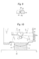
- Fig. 8 shows a second mounting mode of the rotating block 11.
- the mounting portion 18 of the concave strip 13 is attached to the lower portion of the rotary member 22 using the bolt securing device.
- the mounting portion 14 of the convex strip 12 is also attached to the main body 23 using the bolt securing device.
- the convex sliding portion 15 and the concave sliding portion 17 are arranged in a slidable state by being in abutment with each other. In this configuration, the convex sliding portion 15 can be slid stably with respect to the concave sliding portion 17, so that the rotation along a large arc is achieved.
- mounting positions of the rotating blocks 11 with respect to the rotary member 22 are near both ends 22a of the rotary member 22, that is, two positions as shown in Fig. 4 and Fig. 5 .
- the rotating block 11 may be provided only at one position, and if the rotary member 22 is larger, the rotating blocks 11 may be provided at three or more positions.
- the rotary member 22 is formed with rather small edge portions 27 on the both ends 22a in the widthwise direction, and projecting portions 25 are provided at an axial center position 24 of the edge portion 27, that is, as is clear from Figs. 5 , 9, and 10 , at the axial center position 24 as the axis of rotation of the rotary member 22.
- drop preventing holding plates 26 are provided for the projecting portions 25. The drop preventing holding plates 26 are fixed to predetermined positions of the main body 23.
- the rotary member 22 is prevented from being dropped even when the rotary member 22 or the entire press-die is inverted. Since the edge portions 27 are not subjected to bolt securing as in the case of the side portions 2 in the prior art, the width can remarkably be reduced.
- Fig. 10 shows a second mode of the drop preventing mechanism of the rotary member 22.
- the rotary member 22 is formed with projecting portions 28 on the both ends 22a in the widthwise direction at positions lower than the axial center position 24, that is, as is clear from Figs. 5 , 9, and 10 , at positions lower than the axial center position 24 as the axis of rotation of the rotary member 22.
- arcuate-shaped drop preventing holding portions 29 corresponding to the trajectory of rotation of the rotary member 22 are disposed for the projecting portions 28.
- the drop preventing holding portions 29 are fixed to predetermined positions of the main body 23. Edge portions of the projecting portions 28 move along edge portions of the drop preventing holding portions 29 in association with the sliding movement of the rotary member 22.
- the rotating structure of the rotary member 22 configured as described above is such that the rotating blocks 11 slide to allow the rotary member 22 to make rotary motion by pushing and pulling the rotary member 22 with a lift pin or the like (not shown) which can be projected or retracted (see Fig. 7 and Fig. 8 ).
- the center of rotation of the rotary member 22 can be set arbitrarily, that is, design flexibility is improved. Since the side portion 2 and the supporting shaft 4 or the bearing 6 as in the prior art are not necessary, the space corresponding thereto can be omitted, so that the rotary member can be downsized. Accordingly, the downsizing of the press molding apparatus is achieved. In addition, since the components such as the supporting shaft 4 are not necessary, the number of components can be reduced, so that the manufacturing cost of the press molding apparatus can be reduced.
Landscapes
- Engineering & Computer Science (AREA)
- Mechanical Engineering (AREA)
- General Engineering & Computer Science (AREA)
- Press Drives And Press Lines (AREA)
- Mounting, Exchange, And Manufacturing Of Dies (AREA)
- Presses And Accessory Devices Thereof (AREA)
- Shaping Metal By Deep-Drawing, Or The Like (AREA)
- Perforating, Stamping-Out Or Severing By Means Other Than Cutting (AREA)
- Bending Of Plates, Rods, And Pipes (AREA)
- Forging (AREA)
- Pivots And Pivotal Connections (AREA)
Applications Claiming Priority (1)
| Application Number | Priority Date | Filing Date | Title |
|---|---|---|---|
| JP2009239144A JP4597254B1 (ja) | 2009-10-16 | 2009-10-16 | 回動体の回動構造 |
Publications (3)
| Publication Number | Publication Date |
|---|---|
| EP2320102A2 true EP2320102A2 (fr) | 2011-05-11 |
| EP2320102A3 EP2320102A3 (fr) | 2014-01-22 |
| EP2320102B1 EP2320102B1 (fr) | 2015-01-14 |
Family
ID=43425731
Family Applications (1)
| Application Number | Title | Priority Date | Filing Date |
|---|---|---|---|
| EP10187817.1A Not-in-force EP2320102B1 (fr) | 2009-10-16 | 2010-10-15 | Structure rotative pour un outil de formage rotatif |
Country Status (5)
| Country | Link |
|---|---|
| US (1) | US8506281B2 (fr) |
| EP (1) | EP2320102B1 (fr) |
| JP (1) | JP4597254B1 (fr) |
| KR (1) | KR101451187B1 (fr) |
| CN (1) | CN102039343A (fr) |
Cited By (1)
| Publication number | Priority date | Publication date | Assignee | Title |
|---|---|---|---|---|
| WO2013049171A1 (fr) * | 2011-09-26 | 2013-04-04 | Chrysler Group Llc | Came de remplissage tournante, actionnée par un coin, utilisant une selle pour la rotation |
Families Citing this family (2)
| Publication number | Priority date | Publication date | Assignee | Title |
|---|---|---|---|---|
| JP6038216B2 (ja) | 2015-03-30 | 2016-12-07 | 株式会社ユアビジネス | 回動用軸受とその製造方法 |
| CN112135698B (zh) * | 2019-04-25 | 2023-07-14 | 优尔商业株式会社 | 旋转式冲压模具 |
Citations (2)
| Publication number | Priority date | Publication date | Assignee | Title |
|---|---|---|---|---|
| JP2005249019A (ja) | 2004-03-03 | 2005-09-15 | Your Business:Kk | 回動体の支軸形成及び軸支方法と支軸及び軸受け |
| JP2007283352A (ja) | 2006-04-17 | 2007-11-01 | Your Business:Kk | 軸受構造及び該構造を有するプレス成形装置 |
Family Cites Families (12)
| Publication number | Priority date | Publication date | Assignee | Title |
|---|---|---|---|---|
| JPS58218914A (ja) * | 1982-06-15 | 1983-12-20 | 池田物産株式会社 | シ−ト用リクライニングデバイス |
| JPH08256B2 (ja) * | 1993-06-07 | 1996-01-10 | ユミックス株式会社 | 薄板の成形型 |
| US5770123A (en) * | 1994-09-22 | 1998-06-23 | Ebara Corporation | Method and apparatus for energy beam machining |
| JP3490606B2 (ja) * | 1998-03-20 | 2004-01-26 | 富士通株式会社 | 半導体装置製造用金型 |
| JP3492642B2 (ja) * | 2001-03-21 | 2004-02-03 | ユミックス株式会社 | 負角成形型の回転カム移動装置 |
| JP2002347997A (ja) * | 2001-05-29 | 2002-12-04 | Fuji Xerox Co Ltd | 揺動装置及び給紙装置 |
| JP2003062617A (ja) * | 2001-08-29 | 2003-03-05 | Your Business:Kk | 回動体の外れ防止構造 |
| US7258030B2 (en) * | 2003-01-21 | 2007-08-21 | Syron Engineering & Manufacturing, Llc | Failsafe element for rotary cam unit used in a flanged die |
| JP2006116558A (ja) * | 2004-10-20 | 2006-05-11 | Your Business:Kk | 金属板のプレス成形装置 |
| JP4701008B2 (ja) * | 2005-05-25 | 2011-06-15 | 東芝機械株式会社 | ジンバル機構を備えた転写装置 |
| JP2008260061A (ja) * | 2007-03-20 | 2008-10-30 | Umix Co Ltd | 薄板の成形型 |
| JP2009172671A (ja) * | 2008-01-28 | 2009-08-06 | Toyota Motor Corp | プレス加工方法、及びプレス機 |
-
2009
- 2009-10-16 JP JP2009239144A patent/JP4597254B1/ja not_active Expired - Fee Related
-
2010
- 2010-10-13 US US12/903,274 patent/US8506281B2/en not_active Expired - Fee Related
- 2010-10-15 CN CN201010509973XA patent/CN102039343A/zh active Pending
- 2010-10-15 KR KR1020100100831A patent/KR101451187B1/ko not_active Expired - Fee Related
- 2010-10-15 EP EP10187817.1A patent/EP2320102B1/fr not_active Not-in-force
Patent Citations (2)
| Publication number | Priority date | Publication date | Assignee | Title |
|---|---|---|---|---|
| JP2005249019A (ja) | 2004-03-03 | 2005-09-15 | Your Business:Kk | 回動体の支軸形成及び軸支方法と支軸及び軸受け |
| JP2007283352A (ja) | 2006-04-17 | 2007-11-01 | Your Business:Kk | 軸受構造及び該構造を有するプレス成形装置 |
Cited By (2)
| Publication number | Priority date | Publication date | Assignee | Title |
|---|---|---|---|---|
| WO2013049171A1 (fr) * | 2011-09-26 | 2013-04-04 | Chrysler Group Llc | Came de remplissage tournante, actionnée par un coin, utilisant une selle pour la rotation |
| US8739596B2 (en) | 2011-09-26 | 2014-06-03 | Chrysler Group Llc | Wedge activated rotating filler cam utilizing a saddle for rotation |
Also Published As
| Publication number | Publication date |
|---|---|
| US8506281B2 (en) | 2013-08-13 |
| US20110091597A1 (en) | 2011-04-21 |
| JP2011083803A (ja) | 2011-04-28 |
| CN102039343A (zh) | 2011-05-04 |
| KR101451187B1 (ko) | 2014-10-15 |
| JP4597254B1 (ja) | 2010-12-15 |
| EP2320102B1 (fr) | 2015-01-14 |
| EP2320102A3 (fr) | 2014-01-22 |
| KR20110042016A (ko) | 2011-04-22 |
Similar Documents
| Publication | Publication Date | Title |
|---|---|---|
| EP3355159B1 (fr) | Ensemble logement et dispositif électronique | |
| US9752723B2 (en) | Display support device | |
| EP2320102B1 (fr) | Structure rotative pour un outil de formage rotatif | |
| EP1895639A3 (fr) | Aimant permanent et machine rotative à aimants permanents | |
| JP2012501895A5 (fr) | ||
| EP3355155B1 (fr) | Ensemble logement et dispositif électronique | |
| CN107623226B (zh) | 插座 | |
| CN105840696A (zh) | 制动衬片保持装置、制动衬片和衬片支架 | |
| EP2647448B1 (fr) | Dispositif de rabattage à rouleaux | |
| CA2598847C (fr) | Appareil de levage et de positionnement | |
| CN100561001C (zh) | 滚珠滑轨 | |
| KR100988161B1 (ko) | 절곡장치용 금형 | |
| US7363794B2 (en) | Bearing structure and press molding apparatus having the structure | |
| JP5581445B2 (ja) | 溶融金属容器支持装置 | |
| US10059275B2 (en) | Roof molding cap attachment structure and roof molding | |
| JP5161257B2 (ja) | 回転ユニット | |
| CN105276036A (zh) | 一种自适应锁紧装置 | |
| JP6321480B2 (ja) | オフセット型フローティングナット | |
| CN101395411B (zh) | 换挡装置 | |
| US11839809B2 (en) | Operating device | |
| JP2001137946A (ja) | 成形型 | |
| JP6439198B2 (ja) | ディテント機構 | |
| JP6407325B2 (ja) | 支持装置および該支持装置を備えた搬送装置 | |
| KR20170022593A (ko) | 프레스 | |
| JP2010012527A (ja) | 複数個のパンタグラフを設けたテレスコピックカバー |
Legal Events
| Date | Code | Title | Description |
|---|---|---|---|
| PUAI | Public reference made under article 153(3) epc to a published international application that has entered the european phase |
Free format text: ORIGINAL CODE: 0009012 |
|
| AK | Designated contracting states |
Kind code of ref document: A2 Designated state(s): AL AT BE BG CH CY CZ DE DK EE ES FI FR GB GR HR HU IE IS IT LI LT LU LV MC MK MT NL NO PL PT RO RS SE SI SK SM TR |
|
| AX | Request for extension of the european patent |
Extension state: BA ME |
|
| PUAL | Search report despatched |
Free format text: ORIGINAL CODE: 0009013 |
|
| AK | Designated contracting states |
Kind code of ref document: A3 Designated state(s): AL AT BE BG CH CY CZ DE DK EE ES FI FR GB GR HR HU IE IS IT LI LT LU LV MC MK MT NL NO PL PT RO RS SE SI SK SM TR |
|
| AX | Request for extension of the european patent |
Extension state: BA ME |
|
| RIC1 | Information provided on ipc code assigned before grant |
Ipc: F16C 35/02 20060101AFI20131218BHEP Ipc: B21D 19/08 20060101ALI20131218BHEP |
|
| 17P | Request for examination filed |
Effective date: 20140317 |
|
| RBV | Designated contracting states (corrected) |
Designated state(s): AL AT BE BG CH CY CZ DE DK EE ES FI FR GB GR HR HU IE IS IT LI LT LU LV MC MK MT NL NO PL PT RO RS SE SI SK SM TR |
|
| REG | Reference to a national code |
Ref country code: DE Ref legal event code: R079 Ref document number: 602010021769 Country of ref document: DE Free format text: PREVIOUS MAIN CLASS: F16C0035020000 Ipc: B21D0028320000 |
|
| GRAP | Despatch of communication of intention to grant a patent |
Free format text: ORIGINAL CODE: EPIDOSNIGR1 |
|
| RIC1 | Information provided on ipc code assigned before grant |
Ipc: B21D 28/32 20060101AFI20140624BHEP Ipc: B21D 19/08 20060101ALI20140624BHEP |
|
| INTG | Intention to grant announced |
Effective date: 20140729 |
|
| GRAS | Grant fee paid |
Free format text: ORIGINAL CODE: EPIDOSNIGR3 |
|
| GRAA | (expected) grant |
Free format text: ORIGINAL CODE: 0009210 |
|
| AK | Designated contracting states |
Kind code of ref document: B1 Designated state(s): AL AT BE BG CH CY CZ DE DK EE ES FI FR GB GR HR HU IE IS IT LI LT LU LV MC MK MT NL NO PL PT RO RS SE SI SK SM TR |
|
| REG | Reference to a national code |
Ref country code: GB Ref legal event code: FG4D |
|
| REG | Reference to a national code |
Ref country code: CH Ref legal event code: EP |
|
| REG | Reference to a national code |
Ref country code: IE Ref legal event code: FG4D |
|
| REG | Reference to a national code |
Ref country code: AT Ref legal event code: REF Ref document number: 706738 Country of ref document: AT Kind code of ref document: T Effective date: 20150215 |
|
| REG | Reference to a national code |
Ref country code: DE Ref legal event code: R096 Ref document number: 602010021769 Country of ref document: DE Effective date: 20150305 |
|
| REG | Reference to a national code |
Ref country code: NL Ref legal event code: VDEP Effective date: 20150114 |
|
| REG | Reference to a national code |
Ref country code: AT Ref legal event code: MK05 Ref document number: 706738 Country of ref document: AT Kind code of ref document: T Effective date: 20150114 |
|
| REG | Reference to a national code |
Ref country code: LT Ref legal event code: MG4D |
|
| PG25 | Lapsed in a contracting state [announced via postgrant information from national office to epo] |
Ref country code: LT Free format text: LAPSE BECAUSE OF FAILURE TO SUBMIT A TRANSLATION OF THE DESCRIPTION OR TO PAY THE FEE WITHIN THE PRESCRIBED TIME-LIMIT Effective date: 20150114 Ref country code: NO Free format text: LAPSE BECAUSE OF FAILURE TO SUBMIT A TRANSLATION OF THE DESCRIPTION OR TO PAY THE FEE WITHIN THE PRESCRIBED TIME-LIMIT Effective date: 20150414 Ref country code: HR Free format text: LAPSE BECAUSE OF FAILURE TO SUBMIT A TRANSLATION OF THE DESCRIPTION OR TO PAY THE FEE WITHIN THE PRESCRIBED TIME-LIMIT Effective date: 20150114 Ref country code: SE Free format text: LAPSE BECAUSE OF FAILURE TO SUBMIT A TRANSLATION OF THE DESCRIPTION OR TO PAY THE FEE WITHIN THE PRESCRIBED TIME-LIMIT Effective date: 20150114 Ref country code: FI Free format text: LAPSE BECAUSE OF FAILURE TO SUBMIT A TRANSLATION OF THE DESCRIPTION OR TO PAY THE FEE WITHIN THE PRESCRIBED TIME-LIMIT Effective date: 20150114 Ref country code: BG Free format text: LAPSE BECAUSE OF FAILURE TO SUBMIT A TRANSLATION OF THE DESCRIPTION OR TO PAY THE FEE WITHIN THE PRESCRIBED TIME-LIMIT Effective date: 20150414 Ref country code: ES Free format text: LAPSE BECAUSE OF FAILURE TO SUBMIT A TRANSLATION OF THE DESCRIPTION OR TO PAY THE FEE WITHIN THE PRESCRIBED TIME-LIMIT Effective date: 20150114 |
|
| PG25 | Lapsed in a contracting state [announced via postgrant information from national office to epo] |
Ref country code: NL Free format text: LAPSE BECAUSE OF FAILURE TO SUBMIT A TRANSLATION OF THE DESCRIPTION OR TO PAY THE FEE WITHIN THE PRESCRIBED TIME-LIMIT Effective date: 20150114 Ref country code: IS Free format text: LAPSE BECAUSE OF FAILURE TO SUBMIT A TRANSLATION OF THE DESCRIPTION OR TO PAY THE FEE WITHIN THE PRESCRIBED TIME-LIMIT Effective date: 20150514 Ref country code: LV Free format text: LAPSE BECAUSE OF FAILURE TO SUBMIT A TRANSLATION OF THE DESCRIPTION OR TO PAY THE FEE WITHIN THE PRESCRIBED TIME-LIMIT Effective date: 20150114 Ref country code: PL Free format text: LAPSE BECAUSE OF FAILURE TO SUBMIT A TRANSLATION OF THE DESCRIPTION OR TO PAY THE FEE WITHIN THE PRESCRIBED TIME-LIMIT Effective date: 20150114 Ref country code: AT Free format text: LAPSE BECAUSE OF FAILURE TO SUBMIT A TRANSLATION OF THE DESCRIPTION OR TO PAY THE FEE WITHIN THE PRESCRIBED TIME-LIMIT Effective date: 20150114 Ref country code: RS Free format text: LAPSE BECAUSE OF FAILURE TO SUBMIT A TRANSLATION OF THE DESCRIPTION OR TO PAY THE FEE WITHIN THE PRESCRIBED TIME-LIMIT Effective date: 20150114 Ref country code: GR Free format text: LAPSE BECAUSE OF FAILURE TO SUBMIT A TRANSLATION OF THE DESCRIPTION OR TO PAY THE FEE WITHIN THE PRESCRIBED TIME-LIMIT Effective date: 20150415 |
|
| REG | Reference to a national code |
Ref country code: DE Ref legal event code: R097 Ref document number: 602010021769 Country of ref document: DE |
|
| PG25 | Lapsed in a contracting state [announced via postgrant information from national office to epo] |
Ref country code: EE Free format text: LAPSE BECAUSE OF FAILURE TO SUBMIT A TRANSLATION OF THE DESCRIPTION OR TO PAY THE FEE WITHIN THE PRESCRIBED TIME-LIMIT Effective date: 20150114 Ref country code: DK Free format text: LAPSE BECAUSE OF FAILURE TO SUBMIT A TRANSLATION OF THE DESCRIPTION OR TO PAY THE FEE WITHIN THE PRESCRIBED TIME-LIMIT Effective date: 20150114 Ref country code: RO Free format text: LAPSE BECAUSE OF FAILURE TO SUBMIT A TRANSLATION OF THE DESCRIPTION OR TO PAY THE FEE WITHIN THE PRESCRIBED TIME-LIMIT Effective date: 20150114 Ref country code: SK Free format text: LAPSE BECAUSE OF FAILURE TO SUBMIT A TRANSLATION OF THE DESCRIPTION OR TO PAY THE FEE WITHIN THE PRESCRIBED TIME-LIMIT Effective date: 20150114 Ref country code: CZ Free format text: LAPSE BECAUSE OF FAILURE TO SUBMIT A TRANSLATION OF THE DESCRIPTION OR TO PAY THE FEE WITHIN THE PRESCRIBED TIME-LIMIT Effective date: 20150114 |
|
| PLBE | No opposition filed within time limit |
Free format text: ORIGINAL CODE: 0009261 |
|
| STAA | Information on the status of an ep patent application or granted ep patent |
Free format text: STATUS: NO OPPOSITION FILED WITHIN TIME LIMIT |
|
| 26N | No opposition filed |
Effective date: 20151015 |
|
| PG25 | Lapsed in a contracting state [announced via postgrant information from national office to epo] |
Ref country code: IT Free format text: LAPSE BECAUSE OF FAILURE TO SUBMIT A TRANSLATION OF THE DESCRIPTION OR TO PAY THE FEE WITHIN THE PRESCRIBED TIME-LIMIT Effective date: 20150114 |
|
| PG25 | Lapsed in a contracting state [announced via postgrant information from national office to epo] |
Ref country code: SI Free format text: LAPSE BECAUSE OF FAILURE TO SUBMIT A TRANSLATION OF THE DESCRIPTION OR TO PAY THE FEE WITHIN THE PRESCRIBED TIME-LIMIT Effective date: 20150114 |
|
| PG25 | Lapsed in a contracting state [announced via postgrant information from national office to epo] |
Ref country code: LU Free format text: LAPSE BECAUSE OF FAILURE TO SUBMIT A TRANSLATION OF THE DESCRIPTION OR TO PAY THE FEE WITHIN THE PRESCRIBED TIME-LIMIT Effective date: 20151015 Ref country code: BE Free format text: LAPSE BECAUSE OF FAILURE TO SUBMIT A TRANSLATION OF THE DESCRIPTION OR TO PAY THE FEE WITHIN THE PRESCRIBED TIME-LIMIT Effective date: 20150114 |
|
| REG | Reference to a national code |
Ref country code: CH Ref legal event code: PL |
|
| GBPC | Gb: european patent ceased through non-payment of renewal fee |
Effective date: 20151015 |
|
| PG25 | Lapsed in a contracting state [announced via postgrant information from national office to epo] |
Ref country code: MC Free format text: LAPSE BECAUSE OF FAILURE TO SUBMIT A TRANSLATION OF THE DESCRIPTION OR TO PAY THE FEE WITHIN THE PRESCRIBED TIME-LIMIT Effective date: 20150114 |
|
| REG | Reference to a national code |
Ref country code: IE Ref legal event code: MM4A |
|
| PG25 | Lapsed in a contracting state [announced via postgrant information from national office to epo] |
Ref country code: LI Free format text: LAPSE BECAUSE OF NON-PAYMENT OF DUE FEES Effective date: 20151031 Ref country code: GB Free format text: LAPSE BECAUSE OF NON-PAYMENT OF DUE FEES Effective date: 20151015 Ref country code: CH Free format text: LAPSE BECAUSE OF NON-PAYMENT OF DUE FEES Effective date: 20151031 |
|
| REG | Reference to a national code |
Ref country code: FR Ref legal event code: ST Effective date: 20160630 |
|
| PG25 | Lapsed in a contracting state [announced via postgrant information from national office to epo] |
Ref country code: FR Free format text: LAPSE BECAUSE OF NON-PAYMENT OF DUE FEES Effective date: 20151102 |
|
| PG25 | Lapsed in a contracting state [announced via postgrant information from national office to epo] |
Ref country code: IE Free format text: LAPSE BECAUSE OF NON-PAYMENT OF DUE FEES Effective date: 20151015 |
|
| PG25 | Lapsed in a contracting state [announced via postgrant information from national office to epo] |
Ref country code: HU Free format text: LAPSE BECAUSE OF FAILURE TO SUBMIT A TRANSLATION OF THE DESCRIPTION OR TO PAY THE FEE WITHIN THE PRESCRIBED TIME-LIMIT; INVALID AB INITIO Effective date: 20101015 Ref country code: SM Free format text: LAPSE BECAUSE OF FAILURE TO SUBMIT A TRANSLATION OF THE DESCRIPTION OR TO PAY THE FEE WITHIN THE PRESCRIBED TIME-LIMIT Effective date: 20150114 |
|
| PG25 | Lapsed in a contracting state [announced via postgrant information from national office to epo] |
Ref country code: CY Free format text: LAPSE BECAUSE OF FAILURE TO SUBMIT A TRANSLATION OF THE DESCRIPTION OR TO PAY THE FEE WITHIN THE PRESCRIBED TIME-LIMIT Effective date: 20150114 |
|
| PG25 | Lapsed in a contracting state [announced via postgrant information from national office to epo] |
Ref country code: MT Free format text: LAPSE BECAUSE OF FAILURE TO SUBMIT A TRANSLATION OF THE DESCRIPTION OR TO PAY THE FEE WITHIN THE PRESCRIBED TIME-LIMIT Effective date: 20150114 Ref country code: TR Free format text: LAPSE BECAUSE OF FAILURE TO SUBMIT A TRANSLATION OF THE DESCRIPTION OR TO PAY THE FEE WITHIN THE PRESCRIBED TIME-LIMIT Effective date: 20150114 |
|
| PG25 | Lapsed in a contracting state [announced via postgrant information from national office to epo] |
Ref country code: MK Free format text: LAPSE BECAUSE OF FAILURE TO SUBMIT A TRANSLATION OF THE DESCRIPTION OR TO PAY THE FEE WITHIN THE PRESCRIBED TIME-LIMIT Effective date: 20150114 Ref country code: PT Free format text: LAPSE BECAUSE OF FAILURE TO SUBMIT A TRANSLATION OF THE DESCRIPTION OR TO PAY THE FEE WITHIN THE PRESCRIBED TIME-LIMIT Effective date: 20150114 |
|
| PG25 | Lapsed in a contracting state [announced via postgrant information from national office to epo] |
Ref country code: AL Free format text: LAPSE BECAUSE OF FAILURE TO SUBMIT A TRANSLATION OF THE DESCRIPTION OR TO PAY THE FEE WITHIN THE PRESCRIBED TIME-LIMIT Effective date: 20150114 |
|
| PGFP | Annual fee paid to national office [announced via postgrant information from national office to epo] |
Ref country code: DE Payment date: 20181030 Year of fee payment: 9 |
|
| REG | Reference to a national code |
Ref country code: DE Ref legal event code: R119 Ref document number: 602010021769 Country of ref document: DE |
|
| PG25 | Lapsed in a contracting state [announced via postgrant information from national office to epo] |
Ref country code: DE Free format text: LAPSE BECAUSE OF NON-PAYMENT OF DUE FEES Effective date: 20200501 |