EP2315701B1 - Système de contenants empilables à verrouillage mutuel des contenants empilés - Google Patents
Système de contenants empilables à verrouillage mutuel des contenants empilés Download PDFInfo
- Publication number
- EP2315701B1 EP2315701B1 EP09776868A EP09776868A EP2315701B1 EP 2315701 B1 EP2315701 B1 EP 2315701B1 EP 09776868 A EP09776868 A EP 09776868A EP 09776868 A EP09776868 A EP 09776868A EP 2315701 B1 EP2315701 B1 EP 2315701B1
- Authority
- EP
- European Patent Office
- Prior art keywords
- container
- lid
- bottom part
- engagement
- locking
- Prior art date
- Legal status (The legal status is an assumption and is not a legal conclusion. Google has not performed a legal analysis and makes no representation as to the accuracy of the status listed.)
- Active
Links
Images


Classifications
-
- B—PERFORMING OPERATIONS; TRANSPORTING
- B65—CONVEYING; PACKING; STORING; HANDLING THIN OR FILAMENTARY MATERIAL
- B65D—CONTAINERS FOR STORAGE OR TRANSPORT OF ARTICLES OR MATERIALS, e.g. BAGS, BARRELS, BOTTLES, BOXES, CANS, CARTONS, CRATES, DRUMS, JARS, TANKS, HOPPERS, FORWARDING CONTAINERS; ACCESSORIES, CLOSURES, OR FITTINGS THEREFOR; PACKAGING ELEMENTS; PACKAGES
- B65D21/00—Nestable, stackable or joinable containers; Containers of variable capacity
- B65D21/02—Containers specially shaped, or provided with fittings or attachments, to facilitate nesting, stacking, or joining together
- B65D21/0209—Containers specially shaped, or provided with fittings or attachments, to facilitate nesting, stacking, or joining together stackable or joined together one-upon-the-other in the upright or upside-down position
- B65D21/0217—Containers with a closure presenting stacking elements
- B65D21/0223—Containers with a closure presenting stacking elements the closure and the bottom presenting local co-operating elements, e.g. projections and recesses
-
- B—PERFORMING OPERATIONS; TRANSPORTING
- B25—HAND TOOLS; PORTABLE POWER-DRIVEN TOOLS; MANIPULATORS
- B25H—WORKSHOP EQUIPMENT, e.g. FOR MARKING-OUT WORK; STORAGE MEANS FOR WORKSHOPS
- B25H3/00—Storage means or arrangements for workshops facilitating access to, or handling of, work tools or instruments
- B25H3/02—Boxes
-
- B—PERFORMING OPERATIONS; TRANSPORTING
- B65—CONVEYING; PACKING; STORING; HANDLING THIN OR FILAMENTARY MATERIAL
- B65D—CONTAINERS FOR STORAGE OR TRANSPORT OF ARTICLES OR MATERIALS, e.g. BAGS, BARRELS, BOTTLES, BOXES, CANS, CARTONS, CRATES, DRUMS, JARS, TANKS, HOPPERS, FORWARDING CONTAINERS; ACCESSORIES, CLOSURES, OR FITTINGS THEREFOR; PACKAGING ELEMENTS; PACKAGES
- B65D2525/00—Details of other kinds or types of rigid or semi-rigid containers
- B65D2525/28—Handles
- B65D2525/281—Details relating to handles
- B65D2525/286—Details relating to handles movable between two or more stable positions, e.g. a retracted and an extended position
- B65D2525/288—Details relating to handles movable between two or more stable positions, e.g. a retracted and an extended position by pivoting action
Definitions
- the invention relates to a container assembly comprising a plurality of stackable containers, each having an opening having a box-shaped or cup-shaped base and of which at least one of the opening of the lower part associated, for selectively releasing or closing the opening relative to the lower part movable lid, and are formed for vertical stacking such that the lid of a lower container between the lower part of the lower container and the lower part of an immediately above upper container is located, wherein each container at least one coupling device is arranged, with which the lower parts immediately aufrhythmitzender container for Receiving a container assembly consisting of several containers can be releasably fix each other, wherein at least the coupling means of a lower container having a movable coupling means which is mounted on the lid of the container u nd is movable relative to the lid in a coupling position for fixing the container with respect to a container placed on it, in which it is simultaneously in contact with the lower parts of both auffactitzender container.
- the known container assembly includes a container having a base and a pivotally mounted lid which is stackable with a plurality of similar containers in a vertical stacking direction such that its lid is below the base a lid sitting on it comes to rest.
- a coupling device consisting of two each in the form of rotary bolts formed coupling means, one of which is arranged on a pivotable carrying handle. Depending on the pivot position of the handle, the lid is locked or released by the coupling means of the carrying handle with respect to the lower part.
- the second coupling means can also be twisted so that it comes into coupling engagement with the lower part of the upper container.
- the cohesion of two coupled containers is thus accomplished by the connection of the two lower parts. If such a container composite transported by detecting the upper container, the pivot bearing of the coupling means is subjected to a high load, which can cause premature wear, but at least requires a very stable and robust and therefore costly design.
- a packaging container which is stackable with its like and summarized to a container composite by having on its top and its underside over complementary engagement structures which engage with each other when an upper container in a combined plug-and-turn on the bottom Container is placed.
- the engagement structure prevents regionally, near the back of the container, a lifting of the upper container.
- the fixing of the front region of the container takes place by means of an additional coupling device which has a plurality of coupling means designed as a rotary bolt, which are rotatable in such a way that they produce a coupling engagement between the front regions of the containers stacked on one another.
- the container opening is arranged laterally and closable by means of two stackable cover walls which are pivotally mounted on the body of the container.
- the rotatable coupling means allow simultaneous locking of the cover walls with each other and with the cover walls of the container arranged above.
- the DE 299 22 447 U1 describes a container assembly of the type mentioned, which has a plurality of stackable container, each having a lower part and a lid. Each lid is provided with two sliding hooks, which serve to fix the lid on the lower part. The hooks also define abutment surfaces for laterally supporting the base of a top container placed on a lid.
- a container which has a lower part and a lid.
- the lid can be attached by means of locking devices on the lower part.
- a plurality of containers can be stacked, wherein on the cover of the respective lower container arranged and with respect to the locking means separate movable coupling means allow a positive fixing of the upper container on the lid of the lower container.
- each stackable container is equipped with cost-realizable means that allow for simple operation, a stable coupling stacked container.
- the movable coupling means is in the coupling position simultaneously with the lower parts of both aufratitzender container in a lifting of the container from each other preventing releasable coupling engagement.
- the coupling means mounted on the cover are in coupling engagement with the lower parts flanking the cover at the same time, so that the carrying force occurring during the transport of a container composite is transferred at least predominantly directly between the lower parts by the coupling means, so that the storage means provided for movement storage of the coupling means on the cover are relieved.
- This storage means are therefore not subject to increased wear and no special requirements in terms of stability, which favors a cost-effective production.
- the operation of the coupling device is also very simple, since with more or less only a single handle a coupling and decoupling two alsratiitzender Container can be performed.
- a single handling operation on the coupling means is sufficient to bring it into engagement with both the lower part of the associated container and the lower part of a seated upper container in a coupling engagement ensuring a firm cohesion in the stacking direction.
- the movable coupling means of the coupling device is designed as rotatably mounted on the cover, in particular one-piece rotary latch.
- the desired coupling engagement can be established or resolved.
- the coupling position of the rotary latch simultaneously engages anchoring means both stacked container and thus ensures a stable cohesion.
- the anchoring means arranged on the lower part of the container are expediently subdivided into first and second anchoring means spaced apart in the stacking direction.
- the first anchoring means are closer to the lid than the second anchoring means.
- the anchoring means arranged on the lower part of the rotary latch expediently has suitable locking structures.
- the arc centers are in particular on the axis of rotation of the rotary latch. In this way, the locking and unlocking process can take place very easily and it is also possible in the coupling position to ensure a large arcuate contact between the locking structures and the anchoring means, so that even at high load capacity to be transferred only a small surface pressure occurs.
- the anchoring means are preferably formed as projections, in particular as one-piece components of the lower part.
- the locking structures are expediently components of groove-shaped recesses formed on the rotary latch.
- the coupling device can advantageously have a multiple function.
- the movable coupling means is designed in particular to the effect that it is also movable at least in a closed position in which the coupling engagement with a possibly arranged on the container upper container is solved, however, arranged a coupling engagement with the below the lid Lower part is given.
- the closed position is therefore in particular the position in which the rotary latch is displaced when an upper container is to be placed on the lower container or removed from the lower container.
- the closed position is the position that ensures the cohesion between the lid and base when the container is to be transported by itself.
- the closed position is a position deviating from the coupling position with respect to the cover.
- offset locking structures are provided on the rotary latch in its direction of rotation, which in the coupling position and in the closed position are alternately in coupling engagement with one and the same anchoring means arranged on the lower part. If the anchoring means have first and second anchoring means of the type mentioned above, the rotary latch cooperates expediently in each case with the first anchoring means in the coupling position and in the closed position.
- the cooperating in the coupling position and in the closed position alternately with the anchoring means of the lower locking structures are advantageously arranged offset in the direction of rotation on the rotary latch that the rotary latch is rotatable in an open position in which said anchoring means between the locking structures lie and the latter can almost move past the anchoring means to allow an optional raising or lowering of the lid from or to the lower part, if the opening of the lower part is to be selectively released or covered.
- a further function that can be integrated into the at least one coupling device is that of establishing a coupling engagement with only the lower part of an upper container arranged on the lid with simultaneous removal of the coupling engagement with the lower part arranged below the lid.
- this position which can be called a half-coupling position, it is possible to swivel the lid of the container upwards, even if another container is arranged on this lid, this further container remaining fixed on the swing-up lid and therefore the container composite does not have to be dissolved.
- the half coupling position expediently corresponds to a rotational position which is rotated by 90 ° with respect to the coupling position.
- the lid Although it would be possible in principle to form the lid so that it can be removed in its entirety from the lower part, a design with pivotal mounting is recommended with respect to the lower part, so that the lid for opening and closing the container is pivotable.
- At least one coupling device of the type described can be combined in combination with further measures used to produce a contiguous container composite from stacked containers.
- Such additional measures may consist in particular in that a first engagement structure is provided on the upper side of the cover and a second engagement structure is provided on the underside of the lower part, wherein these two engagement structures are matched to one another in a manner that the two containers are in abutting relationship first engaging structure of the lower container and the underlying second engagement structure of the upper container engage each other such that the two containers are secured against displacement transversely to the stacking direction relative to each other and on the other by a local locking a partial lifting of the upper container from the lower container is prevented.
- the latter is done by interlocking engagement of special engagement components of the engagement structures, this locking engagement being made by a relative movement of the two containers when an upper container is placed on the lower container.
- the at least one coupling device is arranged at a distance from the locking region defined by the mutually cooperating Schugreif feltmaschine and holds the two containers in the coupling position together such that the upper container is vertically immovably coupled in that region with the lower container by the engagement structure is not prevented from taking off. This results in a combinatory effect between the engagement structures on the one hand and the at least one coupling device on the other hand.
- the first engagement structure arranged on the cover preferably comprises engagement recesses and the second engagement structure arranged on the lower part comprises engagement projections.
- the engagement projections are simultaneously formed as feet, over which the container can be stably placed on a pad when it is not even stacked on another container. These feet expediently at least partially also form the Schugreifbecker the second engagement structure, which prevent stacked container by engaging in a first engagement structure, the local lifting of the lower container.
- the equipped with this Hintergreiffunktion feet can be referred to as locking feet.
- Other feet that cause only a displacement protection transverse to the stacking direction in conjunction with the first engagement structure can be described as a support feet.
- two spaced-apart locking feet are present on the underside of the lower part, in particular in the vicinity of the back.
- a extending between the two locking feet locking bar may be present, which is locked in the stacked state of two containers with a Deutschengreif beauteil the first engagement structure of the Dekkels.
- the first engagement structure has expediently at least one locking engagement recess having an undercut cross-section with a peripheral engagement projection, which can interlock with the associated locking base and, if present, with a locking bar.
- a single locking engagement recess may be formed to allow simultaneous engagement of all existing locking feet.
- such a trained locking engagement recess can also take over the additional function of a recessed grip, in which one can engage with one hand to carry the container.
- the container can also be transported upright in a manner comparable to a briefcase.
- the container is expediently equipped with a carrying handle arranged in the region of the upper side, which expediently can be pivoted into a non-use position, in which it can be pivoted into a receiving recess formed on the upper side of the lid.
- This receiving recess is expediently formed by a correspondingly large-sized engagement recess of the first engagement structure, which simplifies the production and what, among other things, also favors the use as a recessed grip, as required.
- the container assembly has a plurality of containers of the type described, which may differ from each other in particular in their height dimensions, but which are identical in terms of the coupling device and expediently also the engagement structures, so that they themselves stack in any combination and order and link to a container composite.
- the illustrated container arrangement comprises a container 1, which is designed, for example, by stacking a plurality of containers 1 of its kind in a vertical stacking direction 2, for example FIGS. 5 to 10 To obtain apparent from several aufratitzenden containers 1 container arrangement.
- the container 1 is also preferably equipped with at least one coupling device 3 and with an engagement device 4, which allow aufstandsitzende suitcases releasably coupled to each other such that the container assembly forms a consisting of several contiguous containers 1 container composite, which handled as a unit and in particular transported can be.
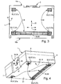
- the container 1 is expediently designed essentially cuboid. Inside it has a receiving space 5 for receiving any objects. Its body 6 is expediently subdivided into a box-shaped or dish-shaped lower part 7 and a lid 8 associated with the opening 12 of the lower part 7, which in turn may also be constructed in a box-shaped or cup-shaped manner.
- the lid 8 may with respect to the lower part 7, for example, from FIGS. 1 and 5 assume apparent covering position. It sits here completely on the edge of the lower part 7 and closes the opening 12, so that the receiving space 5 is covered inaccessible.
- the lid 8 in an example of Figures 2 and 19 apparent open position be moved away from the lower part 7 to expose the opening 12 and the receiving space 5 accessible.
- the container 1 has on the outside a front end face 16a, an opposite rear end face 16b and two also opposite, between the front and the rear end face 16a, 16b extending lateral end faces 16c, 16d.
- These end faces 16a-16d are part of a frame-shaped Peripheral wall 17, which is divided in the embodiment in a belonging to the lower part 7 peripheral wall portion 17a and a cover 8 belonging to the upper peripheral wall portion 17b.
- the two peripheral wall sections 17a, 17b are expediently flush with one another.
- the container 1 has on the outside a lower outer surface referred to as lower side 18 and an upper outer surface designated as upper side 19.
- the bottom 18 is part of a lower part 7 belonging to the bottom wall 22, the top 19 is part of a cover 8 belonging to the ceiling wall 23.
- the bottom wall 22 and the ceiling wall 23 extend in the normal position of use in each case in a horizontal plane, with the height direction of the Container 1 coinciding stacking direction 2 is oriented at right angles thereto.
- FIGS. 5 to 19 are how out FIGS. 5 to 19 can be seen, two containers 1 stacked, the lid 8 of the currently lower container 1 is in the stacking direction 2 between the lower part 7 of the lower container 1 and the lower part 7 of the upper container arranged above 1.
- the arrangement is particularly such that the upper container 1 rests with its bottom wall 22 directly on the ceiling wall 23 of the cover 8 arranged underneath.
- the hinge means 13 are expediently arranged so that the lid pivot axis 14 is associated with the rear end face 16b. To open the container 1, the lid 8 can therefore be swung up in the region of its front.
- transverse direction 24 denotes a direction which is aligned at right angles to the stacking direction 2 and at the same time parallel to the front and rear end faces 16a, 16b.
- a direction perpendicular to the transverse direction 24 is referred to as the depth direction 25.
- the coupling device 3 allows releasably linking a lower container 1 with an upper container 1 currently seated thereon FIG. 7 indicated by dash-dotted lines, could in principle be arranged at several or even on all end faces 16a - 16d of the container 1 in each case at least one coupling device 3. Due to the additional presence of the engagement device 4 is limited in the embodiment, the arrangement of the coupling device 3 on only the front end surface 16a, preferably only a single coupling device 3 is provided, the center of the transverse direction 24, so placed in the center of the front end face 16a is. The handling is thereby greatly simplified.
- a multiple arrangement of in particular independently operable coupling means 3 is particularly recommended when the load to be transmitted by the coupling process is very high and should be selectively distributed to several locations.
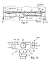
- the coupling device 3 has a mounted on the lid 8 and movable relative to the lid 8 coupling means 26, which in one in the lower half of the FIGS. 5 and 6 as well as the FIGS. 13 and 14 apparent coupling position is movable, in which it simultaneously with the lower parts 7 both auffact sitting container 1 in such coupling engagement is that the two lower parts 7 in the stacking direction 2 can not be moved relative to each other.
- the coupling means 26 prevents the lifting of the upper container, in the opposite direction, the fixation is carried out by the mutual direct vertical support of the container 1 with each other.
- FIG. 12 shows a detailed view of a preferred embodiment of the rotary latch 27 in a rear view.
- the rotary latch 27 is expediently mounted rotatably on the front end face 16a of the cover 8, wherein the rotational axis 29 defined by associated pivot bearing means 28 extends in particular at right angles to the front end face 16a.
- the pivot bearing means 28 consist of a projecting from the front end surface 16a of the lid 8 forward, for example rohrstutzenförmig bearing pin 32 and a preferably integrally and in particular as plastic material rotary latch 27 formed bearing recess 33, with the rotary latch 27 on the bearing pin 32 is rotatably mounted.
- the axial fixation can be effected by any securing means, locking means 34 (for example) serve this purpose. FIGS. 14 and 16 ).
- the pivot bearing means 28 may be provided with indexing 35, which cause the rotary latch 27 fixed in various preferred positions so non-rotatable with respect to the lid 8 is that it can only be turned on by a slightly increased force. It may be, for example, locking means here. Also indexing means 35 of the type, which are based on a locking principle and make an active unlocking with the finger of a hand necessary, would be conceivable.
- the rotary latch 27 has on its the body 6 facing the rear side 36 over several FIG. 12 apparent locking structures 37 which are arranged at a radial distance from the axis of rotation 29, wherein this radial distance is expediently the same for all locking structures 37.
- These locking structures 37 are distributed in the circumferential direction of the rotation axis 29 and arranged at a distance from each other, but are preferably located on a common circular arc 38, the center of which lies on the axis of rotation 29.
- the locking structures 37 comprise at least three locking structures hereinafter referred to as first, second and third locking structures 37a, 37b, 37c, of which the first and second locking structures 37a, 37b are preferably diametrically opposed with respect to the axis of rotation 29, ie on opposite sides of the axis of rotation 29 are arranged.
- the circumferential offset of the first and second locking structures 37a, 37b with respect to the axis of rotation 29 is thus at least substantially 180 °.
- the third locking structure 37c is arranged offset by 90 ° to the two aforementioned locking structures 37a, 37b.
- the rotary latch 27 is particularly handy when it is formed as shown T-shaped, in particular with three substantially equal length latch arms 42 which extend from the bearing recess 33 having locking center radially outward. Conveniently, everyone Latch arm 42 provided with one of the locking structures 37a, 37b, 37c. Between the locking arm 42 having the third locking structure 37c and each of the two other locking arms 42, it is expedient to gap a gap 43 whose determination will be explained below.
- the locking structures 37 consist of the radially outer, the rotation axis 29 facing outer recess flanks depending on a groove-like recess 44 which is formed in the back of the body of the rotary latch 27.
- Each recess 44 expediently has an arcuate extent along the circular arc 38.
- the outer locking flanks acting as locking structures 37 accordingly have an arcuate shape with arc centers lying on the axis of rotation 29.
- the latch arms 42 pivot about the rotation axis 29, wherein a latch arm 42 projecting upwards or downwards in the stacking direction 2 protrudes beyond the cover 8 in the corresponding direction. So it is the distance between the locking structures 37 of the rotation axis 29 is greater than the distance between the rotation axis 29 and the top and bottom of the lid. 8
- the coupling device 3 has as further components via first and second anchoring means 46, 47, which are arranged on the front end face 16a of that lower part 7, to which also the rotary latch 27 bearing cover 8 belongs.
- the two anchoring means 46, 47 are preferably arranged in the stacking direction 2 at a distance below the lid 8, wherein they are expediently aligned in the stacking direction 2 and in particular are spaced apart from each other such that the first anchoring means 26 closer are placed on the lid 8 as the second anchoring means 47.
- the anchoring means 46, 47 in the exemplary embodiment are each formed by an in particular circular arc-shaped projection.
- the thus arcuate first anchoring means 46 are arranged on the lower part 7 such that their curvature corresponds to that of the circular arc 38 and they are arranged on exactly this circular arc 38.
- the curvature of the second anchoring means 47 is opposite to that of the first anchoring means 46.
- the convex surfaces of the two anchoring means 46, 47 face.
- the curvature of the second anchoring means 47 is the same as that of the first anchoring means 46, the second anchoring means 47 being placed spaced from the axis of rotation 29 so that the distance between the second anchoring means 47 of an upper container 1 and the axis of rotation of the container 1 below it is equal is like the distance between the rotation axis 29 and the first anchoring means 46.
- first anchoring means 46 of the lower container 1 and the second anchoring means 47 of the upper container 1 lie together on the circular arc 38 (see FIG. 13 ).
- anchoring means 46, 47 are formed as groove-like depressions, can engage in the anchoring structures formed by projections 37 of the rotary latch 27.
- first and second anchoring means 46, 47 in one unit.
- the anchoring means 46, 47 are overlapped by the first and second locking structures 37a, 37b in the opposite directions with respect to the stacking direction 2, so that the lower parts 7 in the stacking direction 2 can no longer be removed from each other.
- the lid 8 of the lower container 1 can in this case be clamped between the upper and lower flanking parts 7.
- the rotary latch 27 can be positioned in other, each fulfilling a specific function rotary positions.
- the positioning is expediently supported by the indexing means 35.
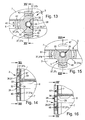
- Another such rotational position is, for example, from FIGS. 1 . 15 and 16 apparent closed position, which also still in the rotary latch of in FIGS. 5 to 10 overhead container 1 is present.
- the closed position makes a difference extending from the coupling position by a 90 ° rotated position, so that the first and second locking structures 37a, 37b come to rest without effect in the region of the front end face 16a of the lid 8 and only the third locking structure 37c is effective, located at a in the closed position downwardly projecting locking arm 42 is located.
- This third locking structure 37c is in coupling engagement with the first anchoring means 46, so that the lid 8 is locked in an irreversible manner with respect to the lower part 7.
- the effective between the lid 8 and the lower part 7 locking force is transmitted here by the lid 8 through the mediation of the pivot bearing means 28, but this is not problematic because it is only a closing force, which is relatively low and the pivot bearing means 28 only little stressed.
- the design of the rotary latch 27 is selected such that in the closed position it does not project into the region in which the second anchoring means 47 of a further, upper container 1 possibly placed on this container is located. Particularly advantageous is a pertinent structure that the rotary latch 27 in the closed position not at all or only slightly beyond the top 19 of the lid 8 protrudes.
- the closed position of the rotary latch 27 can therefore be used to decouple the container composite.
- it serves to lock the lid 8 of a container to be used singly 1 with respect to the lower part 7, so that the Cover 8 is secured in the covering position. Such a condition goes out FIG. 1 out.
- FIG. 2 and 17 Another functional position of the rotary latch 27 is shown in Figures 2 and 17. This is an open position in which the lock between the lid 8 and lower part 7 is released, so that the lid 8 can be swung up to open the container 1 according to arrow 15. Conveniently, this open position, as well as the above-described closed position, simultaneously forms a release position with respect to the seated on the container 1 upper container, with respect to the locking engagement of the rotary latch 27 is canceled both in the open position and in the closed position.
- the above-mentioned gaps 43 arranged between adjacent locking structures 37 gain their significance.
- the width of these gaps 43 is at least as great as the width of the first anchoring means 46, wherein the rotary latch 27 is positioned in the open position such that the gap 43 comes to lie in the region of the first anchoring means 46.
- the first anchoring means 46 are thus arranged in the gap 43, which is large enough to allow the lid 8 to pivot upwardly without this being hindered by the first anchoring means 46.
- the first anchoring means 46 are in the open position so completely out of coupling engagement with any locking structures 37th
- this can be positioned alternatively two open positions, which are achieved starting from the closed position by turning the rotary latch 27 in one or the other direction, wherein the angle of rotation is preferably 45 °. If only one open position is provided, one of the gaps 43 can be omitted.
- the rotary latch 27 can also be in a FIG. 18 spend apparent functional position, which is referred to as half-coupling position, because although the coupling engagement is canceled with the cover 8 belonging to the lower part 7, but not the coupling engagement with the lower part 7 of sitting on the lower container 1 upper container 1.
- the half-coupling position is also again in FIG. 19 in which belonging to the lower container 1 rotary latch 27 can be seen.
- the Halbkoppelwolf is a rotated in the embodiment by 90 ° with respect to the coupling position rotational position.
- the locking arm 42 equipped with the third locking structures 37c protrudes upward, in front of the front end face 16a of the lower part 7 of the upper container 1.
- the third locking structure 37c is in locking engagement with the second anchoring means 47.
- the first and second locking structures 37a, 37b are in the same position as in the closed position according to FIG. 15 , only reversed in their orientation.
- the shape of the rotary bolt 27 may differ from that shown, in particular it would be possible to provide additional wall structures which cover the gaps 41 towards the front, so that the rotary latch 27 has a rather uniform outer contour, for example comparable to the shape of a circle segment.
- the additionally provided engagement device 4 includes a arranged on the upper side 19 of the container 1 first engagement structure 48 and disposed on the underside 18 of the container 1 second engagement structure 49.
- the first engagement structure 48 is located on the outside of the top wall 23 of the lid 8 and second engagement structure 49 on the outside of the bottom wall 22 of the lower part 7.
- the two engagement structures 48, 49 are coordinated so that in the stacked state of two containers 1, the upwardly facing first engagement structure 48 of the lower container 1 and the downwardly facing second engagement structure 49 of upper container 1 engage with each other. This mutual engagement has the effect that the stacked containers 1 are mutually supported transversely to the stacking direction 2 and can not be displaced relative to one another.
- the engagement structures 48, 49 at least partially engage behind transversely to the stacking direction such that an effective locking in the stacking direction, the at least one directly vertically after above directed lifting at least a certain portion of the upper container 1 from the lower container 1 prevented.
- the engagement structures 48, 49 are preferably designed so that they prevent lifting of the rear portion 52 of the upper container 1, however, allow lifting of the front portion 53 of the upper container 1. This circumstance will be out FIG. 10 clear.
- the front portion 53 is inadvertently locked to the lower container 1 and thus the entire upper container 1 enters into a stable connection with the lower container 1, the already explained in detail at least one coupling device 3 is present.
- This coupling device 3 which is expediently located in the region of the front end face 16a, holds in the already explained manner when taking the coupling position, the upper lower part 7 and the lower lower part 7 with the interposition of the lower lid 8 firmly together.
- the first engagement structure 48 consists of a plurality of formed on the top side 19 of the lid 8, distributed over the cover surface engaging grooves 54.
- the second engagement structure 49 consists of several, suitably arranged in the same distribution as the engagement recesses 54 engaging projections 55, the down project over the expediently at least flat outer base 56 of the bottom wall 22.
- feet 57 which are expediently distributed over the underside 18 selectively, wherein the embodiment has a total of four such feet 57, which are placed in the corner areas of the outer base 56 of the bottom wall 22, but in this case to the end faces 16a. 16d each maintain a certain distance.
- Each container 1 can be parked stable on single use with the help of the feet 57 on a ground. The same applies to the use of a container 1 as a lower container of a stacked container arrangement.
- the feet 57 are suitably integrally formed with the body 6, but could also be at least partially releasably secured, if necessary, to allow replacement in the event of wear.
- the rear engagement recess 54b may have an elongated shape with a longitudinal extent extending in the transverse direction 24 and extending parallel to the rear end face 16b.
- the front engaging recesses 54a are like the associated front feet 57 of punctiform shape and have, for example, a square plan.
- the two front legs form in the embodiment pure support feet 57 a, which have a respect to the front engaging recesses 54 a complementary plan shape, so that they are supported in the inserted into the front engaging recesses 54 a state on the inner side walls of the front engaging recesses 54 a, whereby the attached container 1 perpendicular to the stacking direction 2 can not be moved on the lower container 1.
- the structuring of the supporting feet 57a and the front engaging recesses 54a is such that there is no locking in the stacking direction 2, so that the front portion 53 of the upper container 1 can be raised at any time when the coupling means 26 is in the release position.
- the rear feet 57 cooperating with the preferably single rear engagement recess 54b are designed as locking feet 57b.
- Their special feature is that they act as Hintergreif beautician the second engagement structure 49, which are able to engage behind the locking engagement formed for a rear engagement recess 54b inwardly transversely to the stacking direction 2, so that a relative movement in the stacking direction 2 preventing locking engagement exists.
- the rear engagement recess 54b is also referred to as a locking engagement recess.
- each locking stand 57b has its own engagement recess 54, it is also designed as a locking engagement recess.
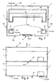
- locking engagement recess 54b receives the rear engagement recess, in particular by realization with an undercut cross-section, for which FIG. 11 an embodiment shows.
- the otherwise upwardly open locking engagement recess 54b has at least at its rear end face 16b adjacent edge region in the depth direction 25 forwardly projecting, preferably rib-shaped rear engagement projection 58, which results in that the locking engagement recess 54b has an opening cross-section is less than the base area of the recess bottom.
- Each locking stand 57b has on the rear end face 16b facing rear side over a suitably wedge-shaped profiled rear gripping portion 62, so that in the transition region to the outer base 56 of the bottom wall 22 results in a gap having a complementary to the Schugreifvorsprung 58 cross-section ( FIG. 11 ).
- the dimensions of the opening of the lock engagement recess 54b are larger in the depth direction 25 than those of each lock stand 57b. The latter can thus be easily inserted from above into the locking engagement recess 54b.
- the upper container 1 To set up an upper container 1 on a lower container 1, the upper container 1 according to FIG. 10 in an inclined position and with the downwardly inclined rear portion 52 ahead of the top 19 of the lower container 1, wherein the locking feet 57b are immersed in the locking engagement recess 54b. At the same time or subsequently, the upper container 1 is pushed or pushed backwards in accordance with arrow 63, so that the rear engagement sections 62 engage in locking engagement with the at least one rear engagement projection 58.
- the area in which this locking engagement takes place may be referred to as the locking area 64.
- the rear portion 52 of the upper case 1 is secured to a vertical lift by the locking engagement between the lock upstands 57b and the lock engagement recess 54b.
- the corresponding vertical securing of the front region 53 takes place by turning the coupling means 26 into the coupling position.
- the insertion of the supporting feet 57a into the front engaging recesses 54a may be facilitated by forming the side wall of the front engaging recesses 54a at least partially as an inclined sliding surface 67.
- the front engagement recesses 54a thus have a larger cross section in the region of their opening than at the bottom surface, wherein this cross-sectional difference is bridged by the inclined sliding surfaces 67. There is thus an automatic centering when placing the upper container instead.
- an additional locking strip 68 can extend between the two spaced in the transverse direction 24 spaced locking feet 57b, which also has a rear engagement portion 62 comparable to that of the locking feet 57b and which expediently the entire space between the two locking Feet 57b bridged.
- This locking bar 68 also forms an engagement component of the second engagement structure 49, which is effective in addition to the locking feet 57b and which increases the length of the locking contact, so that a greater carrying capacity is achieved.
- the measured in the stacking direction 2 height of the locking bar 68 is suitably lower than that of the locking feet 57 b, so that the latter project beyond the locking bar 68 downwards.
- the locking strip 68 is formed integrally with the locking feet 57b. It may in particular be connected in one piece with the body of the lower part 7 in the same way as the feet 57.
- feet 57 Another than the existing in the embodiment number of feet 57 is readily possible.
- a single strip-shaped locking base 57b could be present on the back side, ie comparable to an arrangement in which the locking strip 68 has the same height as the locking feet 57b.
- the container 1 expediently has a carrying handle 72 on its upper side.
- this carrying handle 72 is arranged on the lid.
- it is advantageously designed so that it can either take a apparent from the drawing, pivoted to the top 19 zoom in non-use position or in FIG. 6 indicated, pivoted upward and thus upwardly beyond the top 19 protruding position of use. It is preferably a bow-shaped carrying handle 72 with a U-shaped design.
- an upwardly open receiving recess 73 is formed in the upper side 19 of the lid 8, in which the carrying handle 72 engages sunk in the non-use position.
- this receiving recess 73 is formed directly by the correspondingly large locking engagement recess 54b.
- the said locking engagement recess 54b forms in the embodiment at the same time an open at the top 19 recessed grip 74. This opens up the possibility to transport a single container in a respect to the normal position of use by 90 ° twisted edgewise alignment comparable to a briefcase and doing with one hand to engage from above into the recessed grip 74, wherein the rear grip projection 58 can engage around with the fingers, so that a secure transport is possible.
- the locking feet 54b could also be formed so that their HintergreifAbperforming 62 is oriented towards the front.
- the rear engagement projection 58 would also be located on the edge region of at least one locking engagement recess 54b that is closer to the front end surface 16 and point backwards.
- the entire load capacity between two vertically coupled containers 1 is transmitted via a three-point coupling.
- the three coupling points consist of the interlocking measures in the area of the two locking feet 75b and the rotary bolt 27 arranged at a distance from the locking area 64.
- a certain surface force can also be transmitted by the locking strip 68.
- containers 1 of different heights which have the same coupling devices 3 and engagement devices 4 as the container 1 explained above. In this way, containers 1 differing in size can easily be stacked in any order and combined to form a container composite become.
- the container 1 can in principle also be equipped without engagement device 4 and / or with a different engagement device from the type described.
Claims (17)
- Système de contenants avec plusieurs contenants (1) empilables, dont chacun présente une partie inférieure (7) en forme de caisse ou de coque possédant une ouverture (12) et dont au moins un présente un couvercle (8) mobile pour la libération ou la fermeture au choix de l'ouverture (12) par rapport à la partie inférieure (7), associé à l'ouverture (12) de la partie inférieure (7), et lesquels contenants sont réalisés pour un empilage vertical tel que le couvercle (8) d'un contenant inférieur (1) se situe entre la partie inférieure (7) du contenant inférieur (1) et la partie inférieure (7) d'un contenant (1) supérieur disposé directement dessus, sur chaque contenant (1) étant disposé au moins un système de couplage (3), avec lequel les parties inférieures (7) de contenants (1) logeant directement les uns sur les autres peuvent être fixées mutuellement de manière amovible pour le maintien d'un ensemble de contenants se composant de plusieurs contenants (1),au moins le dispositif de couplage (3) d'un contenant inférieur (1) présentant un moyen de couplage (26) mobile qui est logé sur le couvercle (8) du contenant (1) et peut être déplacé dans une position de couplage par rapport au couvercle (8) pour la fixation du contenant (1) par rapport à un contenant (1) placé sur celui-ci, dans laquelle position il est en contact simultanément avec les parties inférieures (7) de deux contenants (1) logeant l'un sur l'autre, caractérisé en ce que le moyen de couplage (26) mobile est en engagement de couplage amovible empêchant que les contenants (1) ne se décollent l'un de l'autre dans la position de couplage simultanément avec les parties inférieures (7) des deux contenants (1) logeant l'un sur l'autre.
- Système de contenants selon la revendication 1, caractérisé en ce que le moyen de couplage (26) mobile d'au moins un système de couplage (3) est mobile dans une position de fermeture divergeant de la position de couplage, dans laquelle position de fermeture il est découplé d'un contenant (1) supérieur disposé au-dessus du couvercle associé (8) et est en engagement de couplage simultanément avec la partie inférieure (7) disposée au-dessous du couvercle (8) de telle manière que le couvercle (8) soit verrouillé dans une position de recouvrement fermant l'ouverture (12) de la partie inférieure (7) par rapport à cette partie inférieure (7).
- Système de contenants selon la revendication 1 ou 2, caractérisé en ce que le moyen de couplage (26) mobile d'au moins un système de couplage (3) est mobile dans une position de demi-couplage divergeant de la position de couplage, dans laquelle position de demi-couplage il est en engagement de couplage avec la partie inférieure (7) d'un contenant supérieur (1) disposé au-dessus du couvercle associé (8) et est découplé simultanément de la partie inférieure (7) disposée au-dessous du couvercle (8) de sorte que le couvercle (8) puisse se décoller conjointement avec le contenant (1) disposé au-dessus du couvercle (8), de la partie inférieure (7) disposée au-dessous du couvercle (8).
- Système de contenants selon l'une quelconque des revendications 1 à 3, caractérisé en ce que plusieurs dispositifs de couplage (3) répartis sur le contour du contenant (1) sont présents, lesquels peuvent être actionnés indépendamment les uns des autres.
- Système de contenants selon l'une quelconque des revendications 1 à 4, caractérisé en ce que le moyen de couplage mobile (26) d'au moins un système de couplage (3) est réalisé comme un verrou rotatif (27) logé de manière rotative sur le couvercle (8) et en ce que des moyens d'ancrage (46, 47) prévus pour la coopération avec le verrou rotatif (27) sont disposés sur la partie inférieure (7) de telle manière que le verrou rotatif (27) d'un contenant (1) inférieur de deux contenants logeant l'un sur l'autre soit en engagement de couplage simultané lors de l'occupation de la position de couplage avec les moyens d'ancrage (46, 47) des parties inférieures (7) de deux contenants (1).
- Système de contenants selon la revendication 5, caractérisé en ce qu'au moins un système de couplage (3) présente des premiers et seconds moyens d'ancrage (46, 47) espacés l'un de l'autre dans le sens d'empilage (2) du contenant (1), disposés sur la partie inférieure (7), dont les premiers moyens d'ancrage (46) sont placés plus près du couvercle (8) que les seconds moyens d'ancrage (47) de telle manière que le verrou rotatif (27) du contenant (1) inférieur des deux contenants logeant l'un sur l'autre lors de l'occupation de la position de couplage soit en engagement de couplage d'une part avec les premiers moyens d'ancrage (46) disposés sur la partie inférieure (7) du contenant (1) inférieur et d'autre part avec les seconds moyens d'ancrage (47) disposés sur la partie inférieure (7) du contenant supérieur (1).
- Système de contenants selon la revendication 5 ou 6, caractérisé en ce que le verrou rotatif (27) présente, lors de l'occupation de la position de couplage, des structures de verrouillage (37) en engagement de couplage avec les moyens d'ancrage (46, 47) de deux contenants logeant l'un sur l'autre, non seulement les moyens d'ancrage (46, 47) mais aussi les structures de verrouillage (37) étant conçus de manière appropriée en forme d'arc, en particulier avec des centres d'arc se trouvant sur l'axe de rotation (29) du verrou rotatif (27).
- Système de contenants selon la revendication 7, caractérisé en ce que les moyens d'ancrage (46, 47) sont réalisés comme des saillies et les structures de verrouillage (37) sont réalisées comme des éléments de cavités (44) en particulier de type rainure, ou inversement.
- Système de contenants selon l'une quelconque des revendications 5 à 8, caractérisé en ce qu'au moins un système de couplage (3) est disposé sur une surface frontale (16a) du contenant (1) orientée à angle droit par rapport au sens d'empilage (2) du contenant (1), le verrou rotatif (27) pouvant être tourné par rapport à un axe de rotation (29) à angle droit par rapport à cette surface frontale (16a).
- Système de contenants selon l'une quelconque des revendications 5 à 9 en liaison avec la revendication 2, caractérisé en ce que le verrou rotatif (27) dans la position de fermeture occupe une position rotative divergeant de la position de couplage par rapport au couvercle (8).
- Système de contenants selon la revendication 10, caractérisé en ce que le verrou rotatif (27) dispose de structures de verrouillage (37, 37a, 37b, 37c) décalées dans son sens de rotation, qui sont en engagement de couplage alternativement dans la position de couplage et dans la position de fermeture avec les mêmes moyens d'ancrage (46) disposés sur la partie inférieure (7), les structures de verrouillage (37, 37a, 37b, 37c) étant disposées en déport les unes des autres de manière appropriée dans le sens de rotation du loquet rotatif (27) de telle manière que le loquet rotatif (27) puisse être tourné dans une position ouverte, dans laquelle les moyens d'ancrage (46) disposés sur la partie inférieure (7), coopérant dans la position de couplage et dans la position de fermeture avec le loquet rotatif (27) se situent entre les structures de verrouillage (37, 37a, 37b, 37c) et en ce que l'engagement de couplage est par là-même supprimé afin de permettre un décollement du couvercle (8) de la partie inférieure (7) pour la libération de l'ouverture (12) de la partie inférieure (7).
- Système de contenants selon l'une quelconque des revendications 5 à 11 en liaison avec la revendication 3, caractérisé en ce que le loquet rotatif (27) dans la position de demi-couplage occupe dans l'ensemble une position rotative divergeant de la position de couplage par rapport au couvercle (8), les positions rotatives étant tournées dans la position de couplage et dans la position de demi-couplage de manière appropriée de 90° l'une par rapport à l'autre.
- Système de contenants selon l'une quelconque des revendications 1 à 12, caractérisé en ce que le moyen de couplage mobile (26) est réalisé comme un verrou rotatif (27) logé de manière rotative sur le couvercle, qui peut être tourné dans plusieurs positions rotatives différentes, pour lesquelles il s'agit au moins d'une position de couplage, d'une position de fermeture couplant le couvercle (8) juste avec la partie inférieure (7) disposée dessous, d'une position ouverte découplant le couvercle (8) de la partie inférieure (7) disposée dessous et, de manière appropriée, aussi d'une position de demi-couplage découplant le couvercle (8) de la partie inférieure (7) disposée dessous et le couplant simultanément avec la partie inférieure (7) disposée dessus.
- Système de contenants selon l'une quelconque des revendications 1 à 13, caractérisé en ce que le couvercle (8) est logé à distance de la surface frontale (16a) avant du contenant (1) de façon à pouvoir pivoter sur la partie inférieure (7) de telle manière qu'il puisse être pivoté vers le haut en cas de moyen de couplage (26) déplacé dans une position ouverte d'au moins un système de couplage (3) dans la zone avant par rapport à la partie inférieure (7), le contenant présentant de manière appropriée juste un seul système de couplage (3) disposé au milieu de la largeur d'une surface frontale avant (16a) du contenant (1).
- Système de contenants selon l'une quelconque des revendications 1 à 14, caractérisé en ce qu'une première structure d'engagement (48) est présente sur le côté supérieur (19) du couvercle (8) et une seconde structure d'engagement (49) est présente sur le côté inférieur (18) de la partie inférieure (7), les deux structures d'engagement (48, 49) étant adaptées l'une à l'autre de telle manière qu'à l'état empilé l'un sur l'autre de deux contenants (1), la première structure d'engagement (48) supérieure du contenant inférieur (1) et la seconde structure d'engagement (49) inférieure du contenant supérieur (1) s'engagent l'une dans l'autre de telle manière que les deux contenants (1) soient bloqués en déplacement d'une part transversalement au sens d'empilage (2) l'un par rapport à l'autre et d'autre part un verrouillage empêchant un décollement du contenant supérieur (1) du contenant inférieur juste par endroits se présente entre les contenants (1) par des éléments d'engagement arrière (57, 58) des structures d'engagement (48, 49) s'engageant par derrière transversalement au sens d'empilage (2) de sorte que le contenant supérieur (1) puisse être pivoté vers le haut autour de la zone de verrouillage (64) définie par les éléments d'engagement arrière (57, 58) s'engageant par derrière, au moins un système de couplage (3) étant disposé à distance de la zone de verrouillage (64) et empêche un pivotement vers le haut du contenant supérieur (1) du couvercle (8) du contenant inférieur (1) dans la position de couplage de son moyen de couplage (26).
- Système de contenants selon l'une quelconque des revendications 1 à 15, caractérisé en ce qu'au moins deux contenants (1), empilables l'un sur l'autre et pouvant être couplés l'un avec l'autre de manière amovible pour former un ensemble de contenants, du système de contenants présentent au moins un système de couplage (3) avec un moyen de couplage (26) mobile disposé sur son couvercle (8).
- Système de contenants selon l'une quelconque des revendications 1 à 16, caractérisé en ce qu'il présente plusieurs contenants (1) réalisés de manière identique en ce qui concerne leur système de couplage (3).
Applications Claiming Priority (1)
| Application Number | Priority Date | Filing Date | Title |
|---|---|---|---|
| PCT/EP2009/004668 WO2011000385A1 (fr) | 2009-06-29 | 2009-06-29 | Système de contenants empilables à verrouillage mutuel des contenants empilés |
Publications (2)
| Publication Number | Publication Date |
|---|---|
| EP2315701A1 EP2315701A1 (fr) | 2011-05-04 |
| EP2315701B1 true EP2315701B1 (fr) | 2012-02-22 |
Family
ID=41087352
Family Applications (1)
| Application Number | Title | Priority Date | Filing Date |
|---|---|---|---|
| EP09776868A Active EP2315701B1 (fr) | 2009-06-29 | 2009-06-29 | Système de contenants empilables à verrouillage mutuel des contenants empilés |
Country Status (6)
| Country | Link |
|---|---|
| US (1) | US8875888B2 (fr) |
| EP (1) | EP2315701B1 (fr) |
| CN (1) | CN102137795B (fr) |
| AT (1) | ATE546373T1 (fr) |
| CA (1) | CA2735679C (fr) |
| WO (1) | WO2011000385A1 (fr) |
Cited By (12)
| Publication number | Priority date | Publication date | Assignee | Title |
|---|---|---|---|---|
| WO2015000497A1 (fr) | 2013-07-05 | 2015-01-08 | Tts Tooltechnic Systems Ag & Co. Kg | Agencement de récipient |
| DE102015113584A1 (de) * | 2015-08-17 | 2017-02-23 | Adolf Würth GmbH & Co. KG | Montageeinrichtung zum Montieren einer Adaptervorrichtung zum Befestigen von Aufnahmekörpern an einem Kraftfahrzeugsitz |
| WO2018065041A1 (fr) | 2016-10-05 | 2018-04-12 | Festool Gmbh | Unité d'usinage transportable, structure et empilement |
| WO2018065042A1 (fr) | 2016-10-05 | 2018-04-12 | Festool Gmbh | Unité d'usinage transportable et empilement |
| WO2018188736A1 (fr) | 2017-04-11 | 2018-10-18 | Festool Gmbh | Pré-séparateur à cyclone et dispositif |
| CN109890546A (zh) * | 2016-10-05 | 2019-06-14 | 费斯托工具有限责任公司 | 能运输的加工单元 |
| WO2019228648A1 (fr) | 2018-06-01 | 2019-12-05 | TANOS GmbH Verpacken Ordnen Präsentieren | Dispositif de transport |
| WO2019228646A1 (fr) | 2018-06-01 | 2019-12-05 | TANOS GmbH Verpacken Ordnen Präsentieren | Véhicule transport et dispositif de transport |
| WO2019228647A1 (fr) | 2018-06-01 | 2019-12-05 | TANOS GmbH Verpacken Ordnen Präsentieren | Véhicule de transport et dispositif de transport |
| WO2019228649A1 (fr) | 2018-06-01 | 2019-12-05 | TANOS GmbH Verpacken Ordnen Präsentieren | Véhicule de transport et dispositif de transport |
| WO2019228645A1 (fr) | 2018-06-01 | 2019-12-05 | TANOS GmbH Verpacken Ordnen Präsentieren | Véhicule de transport et dispositif de transport |
| WO2023064922A1 (fr) * | 2021-10-15 | 2023-04-20 | Makita U.S.A., Inc. | Système de stockage modulaire avec connectivité de boîte de stockage et caractéristiques de boîte externes |
Families Citing this family (116)
| Publication number | Priority date | Publication date | Assignee | Title |
|---|---|---|---|---|
| KR101782175B1 (ko) | 2009-07-06 | 2017-09-26 | 솔베이(소시에떼아노님) | 알케논의 제조 방법 |
| PT2451765T (pt) | 2009-07-06 | 2017-04-03 | Solvay | Processo para o fabrico de precursores halogenados de alquenonas sob condições específicas |
| US8602217B2 (en) | 2009-12-11 | 2013-12-10 | The Stanley Works Israel Ltd. | Container |
| DE102011108416A1 (de) * | 2011-07-26 | 2013-01-31 | Tts Tooltechnic Systems Ag & Co. Kg | Tragbarer Behälter |
| DE102011110636B4 (de) | 2011-08-18 | 2017-01-26 | Tts Tooltechnic Systems Ag & Co. Kg | Verriegelungseinrichtung und damit ausgestatteter tragbarer Behälter |
| US9907318B2 (en) * | 2013-03-15 | 2018-03-06 | Industrial Revolution, Inc. | Cooling assembly for chilling or freezing liquid ingredients |
| DE102013008630A1 (de) | 2013-05-22 | 2014-11-27 | Festool Gmbh | Tragbarer Behälter, insbesondere für eine Hand-Werkzeugmaschine |
| US9393684B2 (en) | 2014-04-01 | 2016-07-19 | Meridian International Co., Ltd. | Toolbox |
| USD764293S1 (en) * | 2014-09-12 | 2016-08-23 | Shang-Ruei Wang | Cushion packaging material |
| DE102014118452A1 (de) * | 2014-12-11 | 2016-06-16 | Adolf Würth GmbH & Co. KG | Koffer |
| US9809357B2 (en) * | 2015-02-27 | 2017-11-07 | Sonoco Development, Inc. | Container with pivoting latch |
| WO2016142935A1 (fr) * | 2015-03-06 | 2016-09-15 | Keter Plastic Ltd. | Ensembles de réceptacles |
| CA2989919C (fr) * | 2015-07-24 | 2022-12-06 | Tts Tooltechnic Systems Ag & Co. Kg | Dispositif de rangement |
| USD899087S1 (en) * | 2015-07-24 | 2020-10-20 | Tts Tooltechnic Systems Ag & Co. Kg | Storage box |
| USD803560S1 (en) * | 2015-07-24 | 2017-11-28 | Tts Tooltechnic Systems Ag & Co. Kg | Storage box |
| DE102015113590A1 (de) | 2015-08-17 | 2017-02-23 | Adolf Würth GmbH & Co. KG | Adaptervorrichtung für Aufnahmekörper unterschiedlicher Größe |
| DE102015113597A1 (de) | 2015-08-17 | 2017-02-23 | Adolf Würth GmbH & Co. KG | Erweiterungseinrichtung zum räumlichen Erweitern einer Aufnahmefläche einer Adaptervorrichtung |
| DE202015005752U1 (de) * | 2015-08-18 | 2016-11-21 | Plaston Ag | Stapelbarer Koffer mit Kopplungsverbindung und Sicherung |
| DE102015118024A1 (de) | 2015-10-22 | 2017-04-27 | Adolf Würth GmbH & Co. KG | Wandhalterung für stapelbaren Koffer mit multifunktionaler Befestigungsstruktur |
| US11267119B2 (en) * | 2015-12-14 | 2022-03-08 | Milwaukee Electric Tool Corporation | Storage device system |
| CA2952711C (fr) * | 2015-12-22 | 2023-01-03 | Bombardier Recreational Products Inc. | Assemblage de contenants empilables |
| MX2018008682A (es) | 2016-01-14 | 2019-01-28 | Communications Systems Inc | Divisores apilables. |
| US10618692B2 (en) * | 2016-03-09 | 2020-04-14 | Makita Corporation | Stackable cases |
| CA2987892C (fr) | 2016-05-02 | 2021-04-20 | Keter Plastic Ltd. | Ensemble de rangement et mecanisme de raccordement |
| DE102016112853A1 (de) * | 2016-07-13 | 2018-01-18 | Bs Systems Gmbh & Co. Kg | Stapelbarer Systembehälter |
| DE102016112854A1 (de) * | 2016-07-13 | 2018-01-18 | Bs Systems Gmbh & Co. Kg | Stapelbarer Systembehälter |
| CN110248634A (zh) * | 2016-09-28 | 2019-09-17 | 数据医疗技术暨艾德赫技术有限责任公司 | 药物设备 |
| WO2018188735A1 (fr) * | 2017-04-11 | 2018-10-18 | Festool Gmbh | Ensemble comprenant un récipient collecteur de particules et un séparateur à cyclone |
| DK3387979T3 (da) * | 2017-04-11 | 2022-11-14 | Festool Gmbh | Mobilsugeindretning og anordning |
| WO2018213560A1 (fr) | 2017-05-17 | 2018-11-22 | Milwaukee Electric Tool Corporation | Système de dispositif de stockage |
| USD872485S1 (en) | 2017-06-12 | 2020-01-14 | Yeti Coolers, Llc | Container |
| US11685573B2 (en) | 2017-06-12 | 2023-06-27 | Yeti Coolers, Llc | Carry strap for container |
| CA178734S (en) | 2017-06-12 | 2019-05-31 | Yeti Coolers Llc | Container |
| USD838984S1 (en) | 2017-06-12 | 2019-01-29 | Yeti Coolers, Llc | Container |
| USD840150S1 (en) | 2017-06-12 | 2019-02-12 | Yeti Coolers, Llc | Container |
| USD828029S1 (en) | 2017-06-12 | 2018-09-11 | Yeti Coolers, Llc | Container |
| USD872478S1 (en) | 2017-06-12 | 2020-01-14 | Yeti Coolers, Llc | Container |
| USD838983S1 (en) | 2017-06-12 | 2019-01-29 | Yeti Coolers, Llc | Container |
| US11976498B2 (en) | 2017-06-12 | 2024-05-07 | Yeti Coolers, Llc | Container and latching system |
| USD869160S1 (en) | 2017-06-12 | 2019-12-10 | Yeti Coolers, Llc | Container |
| USD828028S1 (en) | 2017-06-12 | 2018-09-11 | Yeti Coolers, Llc | Container |
| USD873020S1 (en) | 2017-06-12 | 2020-01-21 | Yeti Coolers, Llc | Container |
| CN110709332B (zh) | 2017-06-12 | 2021-09-03 | 野醍冷却器有限责任公司 | 容器和闩锁系统 |
| DE102017117182A1 (de) | 2017-07-28 | 2019-01-31 | Adolf Würth Gmbh & Co Kg | Schubladenstruktur für Aufnahmekörper |
| EP3661701A4 (fr) * | 2017-07-31 | 2021-05-19 | Milwaukee Electric Tool Corporation | Système de dispositif de rangement |
| USD896517S1 (en) | 2017-08-09 | 2020-09-22 | Keter Plastic Ltd. | Tool box |
| CN107336898B (zh) * | 2017-08-18 | 2019-04-23 | 铜陵市南亚包装有限责任公司 | 一种放置方便的实用型纸箱 |
| USD880859S1 (en) | 2017-09-05 | 2020-04-14 | Black & Decker Inc. | Tool bit container |
| CN107631248A (zh) * | 2017-10-23 | 2018-01-26 | 扬州市汉讯科技有限公司 | 一种基于薄膜太阳能电池板的led路灯 |
| USD882951S1 (en) | 2017-12-04 | 2020-05-05 | Black & Decker Inc. | Tool bit container |
| USD882950S1 (en) | 2017-12-04 | 2020-05-05 | Black & Decker Inc. | Tool bit container |
| USD882952S1 (en) | 2017-12-04 | 2020-05-05 | Black & Decker Inc. | Tool bit container |
| EP3492226B1 (fr) * | 2017-12-04 | 2022-06-29 | Black & Decker Inc. | Système de conteneur d'outils |
| US10603783B2 (en) | 2017-12-04 | 2020-03-31 | Black & Decker Inc. | Tool container system |
| CN111615481B (zh) | 2017-12-20 | 2022-11-04 | 凯特尔塑料有限公司 | 台车及其机械制动系统 |
| CN111867785A (zh) | 2018-01-24 | 2020-10-30 | 米沃奇电动工具公司 | 工具储存装置 |
| CN108328060A (zh) * | 2018-01-30 | 2018-07-27 | 江苏苏威尔科技有限公司 | 抽屉式组合收纳箱 |
| IL257294A (en) | 2018-02-01 | 2018-03-29 | Milwaukee Electric Tool Corp | Connectable box |
| EP3536460B1 (fr) * | 2018-03-09 | 2021-04-21 | Stanley Black & Decker MEA FZE | Support destiné à maintenir une pièce interchangeable d'un outil |
| AU201816703S (en) * | 2018-05-16 | 2019-01-15 | Festool Gmbh | Container for collecting dust |
| IL259990B (en) | 2018-06-13 | 2022-07-01 | Keter Home And Garden Products Ltd | Connectivity system for various applications |
| IL260225A (en) | 2018-06-24 | 2018-07-31 | Keter Plastic Ltd | pushcart |
| US11486427B2 (en) * | 2018-07-18 | 2022-11-01 | The Stanley Works Israel Ltd. | Stacking latch mechanism |
| US20200078929A1 (en) * | 2018-09-06 | 2020-03-12 | Ersson Co., Ltd. | Stackable Toolbox |
| USD906669S1 (en) * | 2018-09-14 | 2021-01-05 | TANOS GmbH Verpacken Ordnen Präsentieren | Storage box |
| US20220111999A1 (en) * | 2018-09-14 | 2022-04-14 | TANOS GmbH Verpacken Ordnen Präsentieren | Storage device |
| DE102018215669B4 (de) * | 2018-09-14 | 2021-02-04 | TANOS GmbH Verpacken Ordnen Präsentieren | Aufbewahrungseinrichtung und Verfahren zu ihrer Nutzung |
| USD873013S1 (en) | 2018-12-04 | 2020-01-21 | Black & Decker, Inc. | Tool container |
| USD873019S1 (en) | 2018-12-04 | 2020-01-21 | Black & Decker Inc. | Tool container |
| USD858103S1 (en) | 2018-12-04 | 2019-09-03 | Black & Decker Inc. | Tool container |
| USD873012S1 (en) | 2018-12-04 | 2020-01-21 | Black & Decker Inc. | Tool container |
| USD872479S1 (en) | 2018-12-04 | 2020-01-14 | Black & Decker Inc. | Tool container |
| USD874143S1 (en) | 2018-12-04 | 2020-02-04 | Black & Decker Inc. | Tool container |
| USD873018S1 (en) | 2018-12-04 | 2020-01-21 | Black & Decker Inc. | Tool container |
| USD870457S1 (en) | 2018-12-04 | 2019-12-24 | Black & Decker Inc. | Tool container |
| USD873017S1 (en) | 2018-12-04 | 2020-01-21 | Black & Decker Inc. | Tool container |
| USD907445S1 (en) | 2018-12-11 | 2021-01-12 | Yeti Coolers, Llc | Container accessories |
| USD904829S1 (en) | 2018-12-11 | 2020-12-15 | Yeti Coolers, Llc | Container accessories |
| EP3905917B1 (fr) | 2019-01-06 | 2023-07-26 | Yeti Coolers, LLC | Système de bagage |
| DE102019104599A1 (de) * | 2019-02-22 | 2020-08-27 | Aesculap Ag | Stapeleinrichtung für Sterilisiersiebschalen |
| USD967693S1 (en) | 2019-02-26 | 2022-10-25 | Keter Plastic Ltd. | Mounting plate |
| USD898320S1 (en) | 2019-02-26 | 2020-10-06 | Keter Plastic Ltd. | Dolly |
| DK3711623T3 (da) * | 2019-03-20 | 2021-05-25 | Fon Da Tech Co Ltd | Kuffert |
| IL265964A (en) | 2019-04-11 | 2019-07-31 | Milwaukee Electric Tool Corp | A matching system and adapter for it |
| USD919296S1 (en) | 2019-05-31 | 2021-05-18 | Keter Plastic Ltd. | Crate |
| USD923935S1 (en) | 2019-05-31 | 2021-07-06 | Keter Plastic Ltd. | Toolbox |
| USD917977S1 (en) | 2019-05-31 | 2021-05-04 | Keter Plastic Ltd. | Cooler |
| AT522666B1 (de) * | 2019-06-06 | 2022-01-15 | Holzleithner Andreas | Transportbehälter |
| CN110206795B (zh) * | 2019-06-10 | 2023-12-26 | 江苏凯创电子科技有限公司 | 一种用于仪器堆叠或连接互换的装置 |
| CN110254902A (zh) * | 2019-07-04 | 2019-09-20 | 江苏舜天国际集团苏迈克斯工具有限公司 | 可堆叠储物系统 |
| CN114667205A (zh) * | 2019-11-26 | 2022-06-24 | 米沃奇电动工具公司 | 用于模块化储存的固定隔室 |
| AU2021100366A4 (en) * | 2020-01-20 | 2021-04-15 | Techtronic Cordless Gp | Stackable storage system |
| CN111251270A (zh) * | 2020-02-27 | 2020-06-09 | 浙江工贸职业技术学院 | 一种社区用物流配送机器人 |
| IL274945A (en) * | 2020-05-26 | 2021-12-01 | Keter Plastic Ltd | A set of containers and connectivity for them |
| USD951643S1 (en) | 2020-06-30 | 2022-05-17 | Yeti Coolers, Llc | Luggage |
| USD954436S1 (en) | 2020-06-30 | 2022-06-14 | Yeti Coolers, Llc | Luggage |
| USD963344S1 (en) | 2020-06-30 | 2022-09-13 | Yeti Coolers, Llc | Luggage |
| USD961926S1 (en) | 2020-06-30 | 2022-08-30 | Yeti Coolers, Llc | Luggage |
| CN111990266B (zh) * | 2020-08-06 | 2021-12-03 | 台州宝盾科技有限公司 | 宠物托运设备 |
| US11884456B2 (en) | 2020-09-25 | 2024-01-30 | Techtronic Cordless Gp | Tool storage system |
| USD994438S1 (en) | 2020-12-16 | 2023-08-08 | Yeti Coolers, Llc | Container |
| USD985937S1 (en) | 2020-12-16 | 2023-05-16 | Yeti Coolers, Llc | Container |
| USD960648S1 (en) | 2020-12-16 | 2022-08-16 | Yeti Coolers, Llc | Container accessory |
| USD1025600S1 (en) | 2021-01-20 | 2024-05-07 | Techtronic Cordless Gp | Storage container |
| US20220315077A1 (en) * | 2021-03-31 | 2022-10-06 | Juan Jimenez | One Trip Module Dolly |
| US20230110428A1 (en) * | 2021-10-11 | 2023-04-13 | Ford Global Technologies, Llc | Baseplate-based accessory attachment system and attachment method for vehicle |
| US11964632B2 (en) * | 2021-10-11 | 2024-04-23 | Ford Global Technologies, Llc | Vehicle accessory attachment system and attachment method |
| CN113942724A (zh) * | 2021-10-19 | 2022-01-18 | 杭州中纽生物科技有限公司 | 一种红景天提取物颗调节储存温度的存放装置 |
| CN113911529B (zh) * | 2021-10-26 | 2023-02-21 | 湖南嘉力亚新材料有限公司 | 一种石油焦起吊箱 |
| CN113910189A (zh) * | 2021-11-10 | 2022-01-11 | 苏州大可投资咨询有限公司 | 一种模块组合 |
| TWD222441S (zh) * | 2022-01-05 | 2022-12-01 | 大陸商北京石頭世紀科技股份有限公司 | 塵盒 |
| US20230278191A1 (en) * | 2022-03-04 | 2023-09-07 | Meridian International Co., Ltd | Connection structure of module, storage box and storage box assembly |
| US11912477B2 (en) | 2022-06-08 | 2024-02-27 | Yeti Coolers, Llc | Container with handle and latching system |
| USD1024557S1 (en) | 2022-06-08 | 2024-04-30 | Yeti Coolers, Llc | Container |
| US11827075B1 (en) * | 2022-07-26 | 2023-11-28 | Artyc PBC | Temperature-controlled shipping container |
| US20240049878A1 (en) * | 2022-08-12 | 2024-02-15 | Techtronic Cordless Gp | Parts organizer |
Family Cites Families (36)
| Publication number | Priority date | Publication date | Assignee | Title |
|---|---|---|---|---|
| BE378243A (fr) | ||||
| US2634020A (en) | 1948-05-19 | 1953-04-07 | Doehler Jarvis Corp | Tote box |
| US3182856A (en) | 1962-11-20 | 1965-05-11 | I C Bloom | Stacking box construction |
| US3387732A (en) | 1967-03-13 | 1968-06-11 | American Hospital Supply Corp | Hanger construction for parenteral liquid container |
| US3581928A (en) | 1968-10-14 | 1971-06-01 | American Hospital Supply Corp | Hanger construction for medical liquid container |
| DE8018254U1 (de) | 1980-07-08 | 1980-10-02 | Adolf Wuerth Gmbh & Co Kg, 7118 Kuenzelsau | Sortimentskastenregal |
| US4351448A (en) * | 1980-08-08 | 1982-09-28 | General Electric Company | Packaging container for mining and construction tools |
| US4324908A (en) | 1980-12-31 | 1982-04-13 | Standard Oil Company | Preparation of unsaturated acids and esters from saturated carboxylic acid derivatives and carbonyl compounds over phosphate catalysts |
| DE4201264A1 (de) * | 1992-01-18 | 1993-07-22 | Festo Kg | Stapelbarer koffer |
| CA2095095A1 (fr) | 1993-04-28 | 1994-10-29 | Michel Lanoue | Recipient en plastique avec couvercles a joint articule |
| DE4409411A1 (de) | 1994-03-18 | 1995-09-28 | Oped Gmbh Orthopaedische Produ | Verpackungsbehälter |
| US5469961A (en) * | 1994-08-15 | 1995-11-28 | Chang; Chun Y. | Combined minidisc box |
| US5606820A (en) | 1994-10-03 | 1997-03-04 | Suddeth; Melvin E. | Tangle-free fishing lure storage container |
| US5755180A (en) | 1996-03-08 | 1998-05-26 | Smith; Judy | Carrying case for pet accessories |
| US5699925A (en) | 1996-05-14 | 1997-12-23 | Petruzzi; Thomas G. | Interlocking stackable container storage system |
| ATE232487T1 (de) * | 1999-06-02 | 2003-02-15 | Tts Tooltechnic Systems Ag | Behälteranordnung |
| EP0997234A1 (fr) | 1999-06-19 | 2000-05-03 | FESTO Tooltechnic GmbH & Co. | Récipient modulaire |
| DE29922447U1 (de) | 1999-12-21 | 2000-04-06 | Kuo Yu Plastic Enterprise Co | Abdichtbarer Behälter |
| DE20104892U1 (de) | 2001-03-21 | 2001-09-27 | Neolab Migge Laborbedarf Vertr | neoStapelRack, Stapelsystem zur Aufnahme von Boxen für den labortechnischen Bedarf |
| DE20112393U1 (de) | 2001-07-27 | 2001-10-11 | Sinci Ahmet | Gepäckstückanordnung |
| DE20119308U1 (de) | 2001-11-27 | 2002-01-31 | Bekuplast Gmbh | Transport- und Lagerbehälter aus Kunststoff mit integriertem Etikettenhalter |
| US6796430B2 (en) | 2002-02-15 | 2004-09-28 | Doug Mercier | Nesting containers and lids |
| US6761266B2 (en) | 2002-07-03 | 2004-07-13 | Lavonda L. Popish | Personal belongings case |
| US6959507B2 (en) | 2002-10-10 | 2005-11-01 | Bazany Donald J | Injection molded, recessed insert for use in a container and method of using same |
| EP1509240A4 (fr) * | 2002-11-20 | 2008-03-05 | Univ Florida | Identification d'antigenes de l'actinobacillus actinomycetemcomitans utilisee dans le diagnostic, le traitement et le suivi de maladies parodontales |
| DE20314301U1 (de) | 2003-09-17 | 2004-02-26 | Berner Gmbh | Stapelbarer Werkzeugkoffer |
| US7246718B2 (en) * | 2003-10-02 | 2007-07-24 | Zag Industries Ltd. | Toolbox with handle having cover locking mechanism |
| DE20319100U1 (de) | 2003-12-09 | 2004-03-04 | Oberland Engineering Gmbh | Kasten, insbesondere Flaschenkasten aus Kunststoff |
| US7156249B2 (en) | 2004-04-09 | 2007-01-02 | The United States Of America As Represented By The Secretary Of The Navy | Container, and related methods |
| DE202005013057U1 (de) | 2005-08-12 | 2006-12-28 | C. & E. Fein Gmbh | Tragbarer Behälter |
| ITMI20061349A1 (it) * | 2006-07-12 | 2008-01-13 | Marco Alessandro Piacenza | Sistema di contenitori indipendenti impilabili |
| ITMI20061347A1 (it) | 2006-07-12 | 2008-01-13 | Marco Alessandro Piacenza | Sistema di contenitori impilabili ad ingombro ridotto |
| US8322624B2 (en) | 2007-04-10 | 2012-12-04 | Feinics Amatech Teoranta | Smart card with switchable matching antenna |
| ES2573472T3 (es) * | 2007-07-31 | 2016-06-08 | Tts Tooltechnic Systems Ag & Co. Kg | Recipiente de tipo maleta, en particular para el alojamiento de máquinas-herramienta portátiles |
| US7661528B2 (en) | 2007-11-30 | 2010-02-16 | Pwp Industries | Stackable twist-top container system |
| US20090178989A1 (en) | 2008-01-10 | 2009-07-16 | Ronald David Accuardi | Multi-function storage bin |
-
2009
- 2009-06-29 CA CA2735679A patent/CA2735679C/fr active Active
- 2009-06-29 WO PCT/EP2009/004668 patent/WO2011000385A1/fr active Application Filing
- 2009-06-29 AT AT09776868T patent/ATE546373T1/de active
- 2009-06-29 EP EP09776868A patent/EP2315701B1/fr active Active
- 2009-06-29 US US13/061,161 patent/US8875888B2/en active Active
- 2009-06-29 CN CN2009801336924A patent/CN102137795B/zh active Active
Cited By (16)
| Publication number | Priority date | Publication date | Assignee | Title |
|---|---|---|---|---|
| WO2015000497A1 (fr) | 2013-07-05 | 2015-01-08 | Tts Tooltechnic Systems Ag & Co. Kg | Agencement de récipient |
| US10179672B2 (en) | 2013-07-05 | 2019-01-15 | Tts Tooltechnic Systems Ag & Co. Kg | Container assembly |
| DE102015113584A1 (de) * | 2015-08-17 | 2017-02-23 | Adolf Würth GmbH & Co. KG | Montageeinrichtung zum Montieren einer Adaptervorrichtung zum Befestigen von Aufnahmekörpern an einem Kraftfahrzeugsitz |
| CN110023017B (zh) * | 2016-10-05 | 2024-04-02 | 费斯托工具有限责任公司 | 能运输的加工单元和堆叠组件 |
| WO2018065041A1 (fr) | 2016-10-05 | 2018-04-12 | Festool Gmbh | Unité d'usinage transportable, structure et empilement |
| WO2018065042A1 (fr) | 2016-10-05 | 2018-04-12 | Festool Gmbh | Unité d'usinage transportable et empilement |
| CN109862984A (zh) * | 2016-10-05 | 2019-06-07 | 费斯托工具有限责任公司 | 能运输的加工单元、构造和堆叠组件 |
| CN109890546A (zh) * | 2016-10-05 | 2019-06-14 | 费斯托工具有限责任公司 | 能运输的加工单元 |
| CN110023017A (zh) * | 2016-10-05 | 2019-07-16 | 费斯托工具有限责任公司 | 能运输的加工单元和堆叠组件 |
| WO2018188736A1 (fr) | 2017-04-11 | 2018-10-18 | Festool Gmbh | Pré-séparateur à cyclone et dispositif |
| WO2019228646A1 (fr) | 2018-06-01 | 2019-12-05 | TANOS GmbH Verpacken Ordnen Präsentieren | Véhicule transport et dispositif de transport |
| WO2019228647A1 (fr) | 2018-06-01 | 2019-12-05 | TANOS GmbH Verpacken Ordnen Präsentieren | Véhicule de transport et dispositif de transport |
| WO2019228649A1 (fr) | 2018-06-01 | 2019-12-05 | TANOS GmbH Verpacken Ordnen Präsentieren | Véhicule de transport et dispositif de transport |
| WO2019228645A1 (fr) | 2018-06-01 | 2019-12-05 | TANOS GmbH Verpacken Ordnen Präsentieren | Véhicule de transport et dispositif de transport |
| WO2019228648A1 (fr) | 2018-06-01 | 2019-12-05 | TANOS GmbH Verpacken Ordnen Präsentieren | Dispositif de transport |
| WO2023064922A1 (fr) * | 2021-10-15 | 2023-04-20 | Makita U.S.A., Inc. | Système de stockage modulaire avec connectivité de boîte de stockage et caractéristiques de boîte externes |
Also Published As
| Publication number | Publication date |
|---|---|
| WO2011000385A1 (fr) | 2011-01-06 |
| CA2735679A1 (fr) | 2011-01-06 |
| EP2315701A1 (fr) | 2011-05-04 |
| CN102137795B (zh) | 2013-03-06 |
| US8875888B2 (en) | 2014-11-04 |
| CA2735679C (fr) | 2016-08-23 |
| CN102137795A (zh) | 2011-07-27 |
| ATE546373T1 (de) | 2012-03-15 |
| US20110155613A1 (en) | 2011-06-30 |
Similar Documents
| Publication | Publication Date | Title |
|---|---|---|
| EP2315701B1 (fr) | Système de contenants empilables à verrouillage mutuel des contenants empilés | |
| EP2313321B1 (fr) | Système de contenants empilables à verrouillage mutuel des contenants empilés | |
| EP3337645B1 (fr) | Boîte empilable, ensemble comprenant deux boîtes empilées l'une sur l'autre et procédé d'empilage de deux boîtes | |
| EP3294501B1 (fr) | Dispositif de rangement | |
| EP2994274B1 (fr) | Agencement de récipient | |
| DE102015112204B4 (de) | Stapelbarer Behälter zur Ausbildung eines Behälterstapels aus gestapelten und insbesondere gekoppelten Behältern sowie Zubehör zum Bilden eines oberen Abschlusses des Behälterstapels | |
| EP0738506B1 (fr) | Système mobile de support pour malade | |
| EP2759421B1 (fr) | Attelage et dispositif de support de charges d'attelage | |
| EP1018473B1 (fr) | Agencement de récipient | |
| EP3135574A1 (fr) | Couplage | |
| DE202009018589U1 (de) | Behälteranordnung | |
| EP1059240B1 (fr) | Agencement pour conteneur | |
| EP2850011B1 (fr) | Verrouillage de trappe | |
| WO1999015438A1 (fr) | Dispositif de verrouillage pour l'assemblage de conteneurs | |
| DE102017201971A1 (de) | Schwenkbare Armlehne mit Riegelmechanismus | |
| EP0236380A1 (fr) | Casier divisible a bouteilles. | |
| DE3540533C2 (fr) | ||
| DE10148728C1 (de) | Verriegelungsanordnung für Container | |
| DE202009018588U1 (de) | Behälteranordnung | |
| EP1584425B1 (fr) | Conteneur portable | |
| EP2302751B1 (fr) | Unité de connexion destinée à l'utilisation dans un évidement dans une plaque | |
| EP1638745A1 (fr) | Dispositif de maintien | |
| EP1089925B1 (fr) | Piece d'accouplement pour l'assemblage de deux conteneurs superposes | |
| EP2289783A1 (fr) | Adaptateur pour l'application d'objets sur le réservoir d'une motocyclette | |
| DE202009006971U1 (de) | Halteeinrichtung zur Festlegung von Gegenständen an einer Halteschiene eines Operationstisches |
Legal Events
| Date | Code | Title | Description |
|---|---|---|---|
| PUAI | Public reference made under article 153(3) epc to a published international application that has entered the european phase |
Free format text: ORIGINAL CODE: 0009012 |
|
| 17P | Request for examination filed |
Effective date: 20110201 |
|
| AK | Designated contracting states |
Kind code of ref document: A1 Designated state(s): AT BE BG CH CY CZ DE DK EE ES FI FR GB GR HR HU IE IS IT LI LT LU LV MC MK MT NL NO PL PT RO SE SI SK TR |
|
| AX | Request for extension of the european patent |
Extension state: AL BA RS |
|
| GRAP | Despatch of communication of intention to grant a patent |
Free format text: ORIGINAL CODE: EPIDOSNIGR1 |
|
| DAX | Request for extension of the european patent (deleted) | ||
| GRAS | Grant fee paid |
Free format text: ORIGINAL CODE: EPIDOSNIGR3 |
|
| GRAA | (expected) grant |
Free format text: ORIGINAL CODE: 0009210 |
|
| AK | Designated contracting states |
Kind code of ref document: B1 Designated state(s): AT BE BG CH CY CZ DE DK EE ES FI FR GB GR HR HU IE IS IT LI LT LU LV MC MK MT NL NO PL PT RO SE SI SK TR |
|
| REG | Reference to a national code |
Ref country code: GB Ref legal event code: FG4D Free format text: NOT ENGLISH |
|
| REG | Reference to a national code |
Ref country code: CH Ref legal event code: EP Ref country code: CH Ref legal event code: NV Representative=s name: TROESCH SCHEIDEGGER WERNER AG |
|
| REG | Reference to a national code |
Ref country code: AT Ref legal event code: REF Ref document number: 546373 Country of ref document: AT Kind code of ref document: T Effective date: 20120315 |
|
| REG | Reference to a national code |
Ref country code: IE Ref legal event code: FG4D Free format text: LANGUAGE OF EP DOCUMENT: GERMAN |
|
| REG | Reference to a national code |
Ref country code: DE Ref legal event code: R096 Ref document number: 502009002864 Country of ref document: DE Effective date: 20120412 |
|
| REG | Reference to a national code |
Ref country code: SE Ref legal event code: TRGR |
|
| REG | Reference to a national code |
Ref country code: NL Ref legal event code: T3 |
|
| LTIE | Lt: invalidation of european patent or patent extension |
Effective date: 20120222 |
|
| PG25 | Lapsed in a contracting state [announced via postgrant information from national office to epo] |
Ref country code: HR Free format text: LAPSE BECAUSE OF FAILURE TO SUBMIT A TRANSLATION OF THE DESCRIPTION OR TO PAY THE FEE WITHIN THE PRESCRIBED TIME-LIMIT Effective date: 20120222 Ref country code: IS Free format text: LAPSE BECAUSE OF FAILURE TO SUBMIT A TRANSLATION OF THE DESCRIPTION OR TO PAY THE FEE WITHIN THE PRESCRIBED TIME-LIMIT Effective date: 20120622 Ref country code: NO Free format text: LAPSE BECAUSE OF FAILURE TO SUBMIT A TRANSLATION OF THE DESCRIPTION OR TO PAY THE FEE WITHIN THE PRESCRIBED TIME-LIMIT Effective date: 20120522 Ref country code: LT Free format text: LAPSE BECAUSE OF FAILURE TO SUBMIT A TRANSLATION OF THE DESCRIPTION OR TO PAY THE FEE WITHIN THE PRESCRIBED TIME-LIMIT Effective date: 20120222 |
|
| PG25 | Lapsed in a contracting state [announced via postgrant information from national office to epo] |
Ref country code: PT Free format text: LAPSE BECAUSE OF FAILURE TO SUBMIT A TRANSLATION OF THE DESCRIPTION OR TO PAY THE FEE WITHIN THE PRESCRIBED TIME-LIMIT Effective date: 20120622 Ref country code: LV Free format text: LAPSE BECAUSE OF FAILURE TO SUBMIT A TRANSLATION OF THE DESCRIPTION OR TO PAY THE FEE WITHIN THE PRESCRIBED TIME-LIMIT Effective date: 20120222 Ref country code: FI Free format text: LAPSE BECAUSE OF FAILURE TO SUBMIT A TRANSLATION OF THE DESCRIPTION OR TO PAY THE FEE WITHIN THE PRESCRIBED TIME-LIMIT Effective date: 20120222 Ref country code: GR Free format text: LAPSE BECAUSE OF FAILURE TO SUBMIT A TRANSLATION OF THE DESCRIPTION OR TO PAY THE FEE WITHIN THE PRESCRIBED TIME-LIMIT Effective date: 20120523 |
|
| REG | Reference to a national code |
Ref country code: IE Ref legal event code: FD4D |
|
| PG25 | Lapsed in a contracting state [announced via postgrant information from national office to epo] |
Ref country code: CY Free format text: LAPSE BECAUSE OF FAILURE TO SUBMIT A TRANSLATION OF THE DESCRIPTION OR TO PAY THE FEE WITHIN THE PRESCRIBED TIME-LIMIT Effective date: 20120222 |
|
| PG25 | Lapsed in a contracting state [announced via postgrant information from national office to epo] |
Ref country code: SI Free format text: LAPSE BECAUSE OF FAILURE TO SUBMIT A TRANSLATION OF THE DESCRIPTION OR TO PAY THE FEE WITHIN THE PRESCRIBED TIME-LIMIT Effective date: 20120222 Ref country code: RO Free format text: LAPSE BECAUSE OF FAILURE TO SUBMIT A TRANSLATION OF THE DESCRIPTION OR TO PAY THE FEE WITHIN THE PRESCRIBED TIME-LIMIT Effective date: 20120222 Ref country code: DK Free format text: LAPSE BECAUSE OF FAILURE TO SUBMIT A TRANSLATION OF THE DESCRIPTION OR TO PAY THE FEE WITHIN THE PRESCRIBED TIME-LIMIT Effective date: 20120222 Ref country code: CZ Free format text: LAPSE BECAUSE OF FAILURE TO SUBMIT A TRANSLATION OF THE DESCRIPTION OR TO PAY THE FEE WITHIN THE PRESCRIBED TIME-LIMIT Effective date: 20120222 Ref country code: IE Free format text: LAPSE BECAUSE OF FAILURE TO SUBMIT A TRANSLATION OF THE DESCRIPTION OR TO PAY THE FEE WITHIN THE PRESCRIBED TIME-LIMIT Effective date: 20120222 Ref country code: PL Free format text: LAPSE BECAUSE OF FAILURE TO SUBMIT A TRANSLATION OF THE DESCRIPTION OR TO PAY THE FEE WITHIN THE PRESCRIBED TIME-LIMIT Effective date: 20120222 Ref country code: EE Free format text: LAPSE BECAUSE OF FAILURE TO SUBMIT A TRANSLATION OF THE DESCRIPTION OR TO PAY THE FEE WITHIN THE PRESCRIBED TIME-LIMIT Effective date: 20120222 |
|
| PG25 | Lapsed in a contracting state [announced via postgrant information from national office to epo] |
Ref country code: SK Free format text: LAPSE BECAUSE OF FAILURE TO SUBMIT A TRANSLATION OF THE DESCRIPTION OR TO PAY THE FEE WITHIN THE PRESCRIBED TIME-LIMIT Effective date: 20120222 |
|
| PLBI | Opposition filed |
Free format text: ORIGINAL CODE: 0009260 |
|
| 26 | Opposition filed |
Opponent name: MALLOUK, YVES Effective date: 20121122 |
|
| PLAX | Notice of opposition and request to file observation + time limit sent |
Free format text: ORIGINAL CODE: EPIDOSNOBS2 |
|
| PG25 | Lapsed in a contracting state [announced via postgrant information from national office to epo] |
Ref country code: MC Free format text: LAPSE BECAUSE OF NON-PAYMENT OF DUE FEES Effective date: 20120630 |
|
| REG | Reference to a national code |
Ref country code: DE Ref legal event code: R026 Ref document number: 502009002864 Country of ref document: DE Effective date: 20121122 |
|
| PG25 | Lapsed in a contracting state [announced via postgrant information from national office to epo] |
Ref country code: MK Free format text: LAPSE BECAUSE OF FAILURE TO SUBMIT A TRANSLATION OF THE DESCRIPTION OR TO PAY THE FEE WITHIN THE PRESCRIBED TIME-LIMIT Effective date: 20120222 |
|
| PLBB | Reply of patent proprietor to notice(s) of opposition received |
Free format text: ORIGINAL CODE: EPIDOSNOBS3 |
|
| PG25 | Lapsed in a contracting state [announced via postgrant information from national office to epo] |
Ref country code: ES Free format text: LAPSE BECAUSE OF FAILURE TO SUBMIT A TRANSLATION OF THE DESCRIPTION OR TO PAY THE FEE WITHIN THE PRESCRIBED TIME-LIMIT Effective date: 20120602 |
|
| PG25 | Lapsed in a contracting state [announced via postgrant information from national office to epo] |
Ref country code: MT Free format text: LAPSE BECAUSE OF FAILURE TO SUBMIT A TRANSLATION OF THE DESCRIPTION OR TO PAY THE FEE WITHIN THE PRESCRIBED TIME-LIMIT Effective date: 20120222 Ref country code: BG Free format text: LAPSE BECAUSE OF FAILURE TO SUBMIT A TRANSLATION OF THE DESCRIPTION OR TO PAY THE FEE WITHIN THE PRESCRIBED TIME-LIMIT Effective date: 20120522 |
|
| PLAY | Examination report in opposition despatched + time limit |
Free format text: ORIGINAL CODE: EPIDOSNORE2 |
|
| PG25 | Lapsed in a contracting state [announced via postgrant information from national office to epo] |
Ref country code: TR Free format text: LAPSE BECAUSE OF FAILURE TO SUBMIT A TRANSLATION OF THE DESCRIPTION OR TO PAY THE FEE WITHIN THE PRESCRIBED TIME-LIMIT Effective date: 20120222 |
|
| PG25 | Lapsed in a contracting state [announced via postgrant information from national office to epo] |
Ref country code: LU Free format text: LAPSE BECAUSE OF NON-PAYMENT OF DUE FEES Effective date: 20120629 |
|
| PLAH | Information related to despatch of examination report in opposition + time limit modified |
Free format text: ORIGINAL CODE: EPIDOSCORE2 |
|
| PG25 | Lapsed in a contracting state [announced via postgrant information from national office to epo] |
Ref country code: HU Free format text: LAPSE BECAUSE OF FAILURE TO SUBMIT A TRANSLATION OF THE DESCRIPTION OR TO PAY THE FEE WITHIN THE PRESCRIBED TIME-LIMIT Effective date: 20090629 |
|
| PLBC | Reply to examination report in opposition received |
Free format text: ORIGINAL CODE: EPIDOSNORE3 |
|
| PLBP | Opposition withdrawn |
Free format text: ORIGINAL CODE: 0009264 |
|
| PLBD | Termination of opposition procedure: decision despatched |
Free format text: ORIGINAL CODE: EPIDOSNOPC1 |
|
| PLBM | Termination of opposition procedure: date of legal effect published |
Free format text: ORIGINAL CODE: 0009276 |
|
| STAA | Information on the status of an ep patent application or granted ep patent |
Free format text: STATUS: OPPOSITION PROCEDURE CLOSED |
|
| 27C | Opposition proceedings terminated |
Effective date: 20150612 |
|
| REG | Reference to a national code |
Ref country code: FR Ref legal event code: PLFP Year of fee payment: 8 |
|
| REG | Reference to a national code |
Ref country code: FR Ref legal event code: PLFP Year of fee payment: 9 |
|
| REG | Reference to a national code |
Ref country code: FR Ref legal event code: PLFP Year of fee payment: 10 |
|
| PGFP | Annual fee paid to national office [announced via postgrant information from national office to epo] |
Ref country code: NL Payment date: 20230620 Year of fee payment: 15 Ref country code: FR Payment date: 20230622 Year of fee payment: 15 Ref country code: DE Payment date: 20230621 Year of fee payment: 15 |
|
| PGFP | Annual fee paid to national office [announced via postgrant information from national office to epo] |
Ref country code: SE Payment date: 20230622 Year of fee payment: 15 Ref country code: AT Payment date: 20230616 Year of fee payment: 15 |
|
| PGFP | Annual fee paid to national office [announced via postgrant information from national office to epo] |
Ref country code: BE Payment date: 20230619 Year of fee payment: 15 |
|
| PGFP | Annual fee paid to national office [announced via postgrant information from national office to epo] |
Ref country code: IT Payment date: 20230630 Year of fee payment: 15 Ref country code: GB Payment date: 20230622 Year of fee payment: 15 Ref country code: CH Payment date: 20230702 Year of fee payment: 15 |