EP2310477B1 - Verfahren und vorrichtung zum anfahren von mit brennstaub betriebenen vergasungsreaktoren - Google Patents
Verfahren und vorrichtung zum anfahren von mit brennstaub betriebenen vergasungsreaktoren Download PDFInfo
- Publication number
- EP2310477B1 EP2310477B1 EP09777194.3A EP09777194A EP2310477B1 EP 2310477 B1 EP2310477 B1 EP 2310477B1 EP 09777194 A EP09777194 A EP 09777194A EP 2310477 B1 EP2310477 B1 EP 2310477B1
- Authority
- EP
- European Patent Office
- Prior art keywords
- burner
- combustible
- dust
- gas
- burners
- Prior art date
- Legal status (The legal status is an assumption and is not a legal conclusion. Google has not performed a legal analysis and makes no representation as to the accuracy of the status listed.)
- Active
Links
- 239000000428 dust Substances 0.000 title claims description 80
- 238000000034 method Methods 0.000 title claims description 46
- 239000000446 fuel Substances 0.000 claims description 102
- 239000007789 gas Substances 0.000 claims description 78
- 239000000203 mixture Substances 0.000 claims description 68
- 230000001105 regulatory effect Effects 0.000 claims description 22
- VNWKTOKETHGBQD-UHFFFAOYSA-N methane Chemical compound C VNWKTOKETHGBQD-UHFFFAOYSA-N 0.000 claims description 12
- 230000008569 process Effects 0.000 claims description 7
- 239000000571 coke Substances 0.000 claims description 5
- 230000008878 coupling Effects 0.000 claims description 5
- 238000010168 coupling process Methods 0.000 claims description 5
- 238000005859 coupling reaction Methods 0.000 claims description 5
- 238000011144 upstream manufacturing Methods 0.000 claims description 4
- 230000006978 adaptation Effects 0.000 claims description 3
- 239000003245 coal Substances 0.000 claims description 3
- 239000003077 lignite Substances 0.000 claims description 3
- 239000003345 natural gas Substances 0.000 claims description 3
- 239000004449 solid propellant Substances 0.000 claims description 3
- 239000002028 Biomass Substances 0.000 claims description 2
- 239000003415 peat Substances 0.000 claims description 2
- 239000002006 petroleum coke Substances 0.000 claims description 2
- 238000002309 gasification Methods 0.000 description 72
- 239000002737 fuel gas Substances 0.000 description 69
- 230000015572 biosynthetic process Effects 0.000 description 20
- 238000003786 synthesis reaction Methods 0.000 description 19
- 230000033228 biological regulation Effects 0.000 description 12
- 230000001276 controlling effect Effects 0.000 description 8
- 241001156002 Anthonomus pomorum Species 0.000 description 7
- QVGXLLKOCUKJST-UHFFFAOYSA-N atomic oxygen Chemical compound [O] QVGXLLKOCUKJST-UHFFFAOYSA-N 0.000 description 7
- 230000000875 corresponding effect Effects 0.000 description 7
- 238000011143 downstream manufacturing Methods 0.000 description 7
- 239000001301 oxygen Substances 0.000 description 7
- 229910052760 oxygen Inorganic materials 0.000 description 7
- 230000008901 benefit Effects 0.000 description 5
- 230000008859 change Effects 0.000 description 4
- 239000011261 inert gas Substances 0.000 description 4
- OKKJLVBELUTLKV-UHFFFAOYSA-N Methanol Chemical compound OC OKKJLVBELUTLKV-UHFFFAOYSA-N 0.000 description 3
- 239000003795 chemical substances by application Substances 0.000 description 3
- 238000001514 detection method Methods 0.000 description 3
- 238000010304 firing Methods 0.000 description 3
- QGZKDVFQNNGYKY-UHFFFAOYSA-N Ammonia Chemical compound N QGZKDVFQNNGYKY-UHFFFAOYSA-N 0.000 description 2
- IJGRMHOSHXDMSA-UHFFFAOYSA-N Atomic nitrogen Chemical compound N#N IJGRMHOSHXDMSA-UHFFFAOYSA-N 0.000 description 2
- 206010016754 Flashback Diseases 0.000 description 2
- UFHFLCQGNIYNRP-UHFFFAOYSA-N Hydrogen Chemical compound [H][H] UFHFLCQGNIYNRP-UHFFFAOYSA-N 0.000 description 2
- ATUOYWHBWRKTHZ-UHFFFAOYSA-N Propane Chemical compound CCC ATUOYWHBWRKTHZ-UHFFFAOYSA-N 0.000 description 2
- 238000002485 combustion reaction Methods 0.000 description 2
- 238000011161 development Methods 0.000 description 2
- 230000018109 developmental process Effects 0.000 description 2
- 230000000694 effects Effects 0.000 description 2
- 239000001257 hydrogen Substances 0.000 description 2
- 229910052739 hydrogen Inorganic materials 0.000 description 2
- 239000007788 liquid Substances 0.000 description 2
- 239000000243 solution Substances 0.000 description 2
- UGFAIRIUMAVXCW-UHFFFAOYSA-N Carbon monoxide Chemical compound [O+]#[C-] UGFAIRIUMAVXCW-UHFFFAOYSA-N 0.000 description 1
- OTMSDBZUPAUEDD-UHFFFAOYSA-N Ethane Chemical compound CC OTMSDBZUPAUEDD-UHFFFAOYSA-N 0.000 description 1
- 150000001335 aliphatic alkanes Chemical class 0.000 description 1
- 229910021529 ammonia Inorganic materials 0.000 description 1
- 239000001273 butane Substances 0.000 description 1
- 229910002091 carbon monoxide Inorganic materials 0.000 description 1
- 239000012159 carrier gas Substances 0.000 description 1
- 230000002596 correlated effect Effects 0.000 description 1
- 238000002347 injection Methods 0.000 description 1
- 239000007924 injection Substances 0.000 description 1
- 238000005259 measurement Methods 0.000 description 1
- 230000007246 mechanism Effects 0.000 description 1
- IJDNQMDRQITEOD-UHFFFAOYSA-N n-butane Chemical compound CCCC IJDNQMDRQITEOD-UHFFFAOYSA-N 0.000 description 1
- OFBQJSOFQDEBGM-UHFFFAOYSA-N n-pentane Natural products CCCCC OFBQJSOFQDEBGM-UHFFFAOYSA-N 0.000 description 1
- 229910052757 nitrogen Inorganic materials 0.000 description 1
- 239000002245 particle Substances 0.000 description 1
- 239000001294 propane Substances 0.000 description 1
- 230000004044 response Effects 0.000 description 1
- 238000007789 sealing Methods 0.000 description 1
- 239000007787 solid Substances 0.000 description 1
- XLYOFNOQVPJJNP-UHFFFAOYSA-N water Substances O XLYOFNOQVPJJNP-UHFFFAOYSA-N 0.000 description 1
- 238000005303 weighing Methods 0.000 description 1
Images

Classifications
-
- C—CHEMISTRY; METALLURGY
- C10—PETROLEUM, GAS OR COKE INDUSTRIES; TECHNICAL GASES CONTAINING CARBON MONOXIDE; FUELS; LUBRICANTS; PEAT
- C10J—PRODUCTION OF PRODUCER GAS, WATER-GAS, SYNTHESIS GAS FROM SOLID CARBONACEOUS MATERIAL, OR MIXTURES CONTAINING THESE GASES; CARBURETTING AIR OR OTHER GASES
- C10J3/00—Production of combustible gases containing carbon monoxide from solid carbonaceous fuels
- C10J3/02—Fixed-bed gasification of lump fuel
- C10J3/20—Apparatus; Plants
- C10J3/30—Fuel charging devices
-
- C—CHEMISTRY; METALLURGY
- C10—PETROLEUM, GAS OR COKE INDUSTRIES; TECHNICAL GASES CONTAINING CARBON MONOXIDE; FUELS; LUBRICANTS; PEAT
- C10J—PRODUCTION OF PRODUCER GAS, WATER-GAS, SYNTHESIS GAS FROM SOLID CARBONACEOUS MATERIAL, OR MIXTURES CONTAINING THESE GASES; CARBURETTING AIR OR OTHER GASES
- C10J3/00—Production of combustible gases containing carbon monoxide from solid carbonaceous fuels
- C10J3/46—Gasification of granular or pulverulent flues in suspension
- C10J3/48—Apparatus; Plants
- C10J3/50—Fuel charging devices
-
- C—CHEMISTRY; METALLURGY
- C10—PETROLEUM, GAS OR COKE INDUSTRIES; TECHNICAL GASES CONTAINING CARBON MONOXIDE; FUELS; LUBRICANTS; PEAT
- C10J—PRODUCTION OF PRODUCER GAS, WATER-GAS, SYNTHESIS GAS FROM SOLID CARBONACEOUS MATERIAL, OR MIXTURES CONTAINING THESE GASES; CARBURETTING AIR OR OTHER GASES
- C10J3/00—Production of combustible gases containing carbon monoxide from solid carbonaceous fuels
- C10J3/72—Other features
- C10J3/723—Controlling or regulating the gasification process
-
- C—CHEMISTRY; METALLURGY
- C10—PETROLEUM, GAS OR COKE INDUSTRIES; TECHNICAL GASES CONTAINING CARBON MONOXIDE; FUELS; LUBRICANTS; PEAT
- C10J—PRODUCTION OF PRODUCER GAS, WATER-GAS, SYNTHESIS GAS FROM SOLID CARBONACEOUS MATERIAL, OR MIXTURES CONTAINING THESE GASES; CARBURETTING AIR OR OTHER GASES
- C10J3/00—Production of combustible gases containing carbon monoxide from solid carbonaceous fuels
- C10J3/72—Other features
- C10J3/726—Start-up
-
- C—CHEMISTRY; METALLURGY
- C10—PETROLEUM, GAS OR COKE INDUSTRIES; TECHNICAL GASES CONTAINING CARBON MONOXIDE; FUELS; LUBRICANTS; PEAT
- C10J—PRODUCTION OF PRODUCER GAS, WATER-GAS, SYNTHESIS GAS FROM SOLID CARBONACEOUS MATERIAL, OR MIXTURES CONTAINING THESE GASES; CARBURETTING AIR OR OTHER GASES
- C10J2200/00—Details of gasification apparatus
- C10J2200/15—Details of feeding means
- C10J2200/152—Nozzles or lances for introducing gas, liquids or suspensions
-
- C—CHEMISTRY; METALLURGY
- C10—PETROLEUM, GAS OR COKE INDUSTRIES; TECHNICAL GASES CONTAINING CARBON MONOXIDE; FUELS; LUBRICANTS; PEAT
- C10J—PRODUCTION OF PRODUCER GAS, WATER-GAS, SYNTHESIS GAS FROM SOLID CARBONACEOUS MATERIAL, OR MIXTURES CONTAINING THESE GASES; CARBURETTING AIR OR OTHER GASES
- C10J2300/00—Details of gasification processes
- C10J2300/09—Details of the feed, e.g. feeding of spent catalyst, inert gas or halogens
- C10J2300/0913—Carbonaceous raw material
- C10J2300/093—Coal
- C10J2300/0933—Coal fines for producing water gas
-
- C—CHEMISTRY; METALLURGY
- C10—PETROLEUM, GAS OR COKE INDUSTRIES; TECHNICAL GASES CONTAINING CARBON MONOXIDE; FUELS; LUBRICANTS; PEAT
- C10J—PRODUCTION OF PRODUCER GAS, WATER-GAS, SYNTHESIS GAS FROM SOLID CARBONACEOUS MATERIAL, OR MIXTURES CONTAINING THESE GASES; CARBURETTING AIR OR OTHER GASES
- C10J2300/00—Details of gasification processes
- C10J2300/12—Heating the gasifier
- C10J2300/1223—Heating the gasifier by burners
Definitions
- the invention relates to a method and a device for starting gasification reactors which are operated with fuel dust.
- High unit power gasification reactors in particular more than 200 MW, are equipped in a known manner with multiple burners for the supply of gasification agent and fuel, regardless of whether gas, solid or liquid fuel is used. Load changes are made here mainly by the switching on and off of the arranged at the head of the gasification reactor single burner and to a limited extent with a modified fuel supply by means of variable differential pressure setting between the gasification reactor and dosing for dust injection.
- the dust outlet speed at the burner must not be below a minimum of 3 to 5 m / s to avoid flashbacks.
- a method and apparatus for controlled delivery of fuel dust in an entrained flow gasifier is described.
- the method differs from previously known solutions mainly in that an auxiliary gas is introduced into the dosing in the immediate vicinity of the dosing for the fuel dust and is controlled by the resulting differential pressure change between dosing and burner the dust mass flow even at low power. Due to the very different flow behavior of many fuel dusts, this method is only limitedly suitable for load control of large-capacity gasification reactors.
- DE 10 2006 030 079 A1 is a method for commissioning a gasification reactor using a Fuel gas when starting disclosed to reduce the ignition heat demand of the burner.
- a central ignition and pilot burner is first ignited with a fuel gas-gas mixture and immediately increased the performance of the pilot burner and the pressure of the gasification reactor including downstream Rohgassysteme up to the maximum ignition and pilot burner output and the operating pressure of the system.
- the dust burner surrounding the ignition and pilot burners are also ignited with a fuel gas-gas mixture mixture through the existing ignition and pilot burner flame. Once this is done, the fuel is added to the reactor by sequential opening of the supply lines and ignited. The fuel gas supply is terminated after commissioning of the burner with fuel dust.
- a device that allows starting a gasification reactor for fuel dusts in such a way that no pressure surges caused by the suddenly released during startup gas amount is not known from the prior art.
- the present invention based on the object to provide a method and apparatus for starting a gasification reactor, which avoids the pressure surges by the sudden release of gas during startup gas in the process stage downstream of the gasification reactor and does not require flaring ,
- One embodiment relates to a method for starting up a gasification reactor.
- a first composition of combustible dust and fuel gas with which a first burner is charged and ignited, regulated depending on the amount of fuel in the next composition of fuel dust and fuel gas, which is supplied to the second burner for igniting, after the first burner was ignited.
- the start-up of each burner of the gasification reactor takes place under controlled adaptation of the supply of the fuel load to the previously ignited burner.
- measuring devices determines the recorded measurements to a control and regulation unit for the Brennstaubmengen - And outputs fuel gas streams for the burner. The measured values are compared by the control unit with corresponding setpoints. If the measured values do not agree with the nominal values, the quantities of combustible dust and fuel gas for the burners are adjusted by the control unit.
- the first burner is charged with a fuel-fuel mixture and ignited, the composition when igniting a next burner a further combustion dust-fuel gas mixture is adjusted regulated as a function of its composition, so that no pressure surges arise during startup.
- this method step can also be carried out analogously with further burners, so that a fuel composition of a previously ignited burner is regulated after the ignition of a further burner as a function of the quantity of fuel which has been supplied to the subsequently ignited burner.
- a fuel composition of a previously ignited burner is regulated after the ignition of a further burner as a function of the quantity of fuel which has been supplied to the subsequently ignited burner.
- the inventive method offers by the control possibility the advantage that the formation of pressure surges by liberated gas, which otherwise could not be utilized and which would have to be flared, and thus is disadvantageous for subsequent process stages, is avoided.
- a much more uniform amount of dust flow from the metering vessel for the respective burner can be secured, since the pressure difference between gasification reactor and metering causes the promotion of the fuel dust in the gasification reactor.
- All the individual burners 7 of the plurality of burners 7 are ignited one after the other, the burning load during ignition of a single burner being in the range of up to 30% of the maximum output of the individual burner 7.
- natural gas with a methane content of more than 60% by volume is used as fuel gas.
- An embodiment of the device for carrying out the method according to the invention describes a gasification reactor with a plurality of burners and a metering vessel for combustible dust, which is connected via a plurality of dense flow conveying lines with a corresponding burner.
- a dust flow control element for controlling a quantity of pulverized fuel is advantageously arranged in each dense flow conveying line.
- the device has at least one admixing device for a fuel gas for controlling a fuel gas quantity for each dense flow conveying line.
- an operative coupling of the dust flow control elements with the admixing devices is provided for controlling the fuel compositions in relation to a total fuel load of combustible dust and fuel gas.
- the device comprises a control and regulation unit, which provides the operative coupling between the fuel flow control device and admixing device, as well as downstream of the gasification reactor arranged measuring devices for the determination of gas quantities and / or their compositions of a synthesis gas.
- the measured value output of the measuring instruments is connected to the control and regulation unit for a comparison of measured values with corresponding desired values in the control and regulation unit. In this case, if the measured values do not agree with the desired values and depending on each other, the fuel dust flow rates through the fuel dust flow control devices and the fuel gas streams through the admixing devices can be adjusted by the control and regulation unit.
- the operational coupling provided by the control and regulation unit of the Brennstaubstrom-control devices and the Zumischvorraumen allows control of the amount and composition of the total, the burners supplied fuel load from fuel dust and fuel gas in the gasification reactor in the ignition of other burners.
- DE 10 2006 030 079 A1 merely describes a controller for supplying fuel gas and oxygen-containing gasification agent and for opening the supply of fuel dust.
- a safety system monitors the fuel gas quantity and amount of oxygen as well as the amount of fuel dust.
- measuring devices are provided downstream of the gasification reactor, which provide measured values relating to the amount and / or composition of a synthesis gas generated, as a function of which the fuel dust flow control devices and admixing devices are controlled by the control and regulation unit to determine the composition of the fuel dust / fuel gas mixture when firing more burners to regulate.
- Preferred embodiments relate to the arrangement of the mixing devices for fuel gas.
- start-up of the gasification reactor is understood to mean the start-up thereof by igniting the burners. If all the burners of the gasification reactor burn, then the startup is complete and the gasification reactor operates in normal operation.
- fuel load refers to the mass or mass flow of fuel, whether gas, liquid and / or solid fuel, that is reacted by a gasification reactor.
- a burner of a gasification reactor must be operated at a "minimum exit velocity" at the burner mouth during ignition, which is in the range of 3 to 5 m / s, to avoid flashbacks.
- synthesis gas consisting of carbon monoxide and hydrogen is recovered from the fuel used, and the synthesis gas produced is reused in downstream process stages, for example in the methanol, oxo or Fischer-Tropsch synthesis.
- the hydrogen produced is also used separately, in the ammonia synthesis according to Haber-Bosch with nitrogen, as an energy carrier or reducing or hydrogenating agent.
- the inventive method for starting gasification reactors which have two or more burners, each of which is fed via its associated dense stream conveying line with fuel dust from a metering vessel and a gas delivery line with fuel gas, comprises providing a fuel mixture of fuel dust and fuel gas in front of a Time of ignition of a burner.
- the fuel gas used for this purpose is not an auxiliary gas in the sense of a gas used for pressure equalization between metering vessel and gasification reactor, which is often an inert gas, but a fuel gas with calorific value.
- a natural gas may preferably be used with a methane content of more than 60%, other alkanes such as ethane, propane and butane and mixtures thereof can be used; suitable fuel gases are known in the art.
- a first composition of combustible dust and fuel gas with which a first burner is charged for ignition, is ignited after the ignition of a second burner, which follows the ignition of the first burner and is charged with a second composition of combustible dust and fuel gas, controlled in response to the amount of fuel that was supplied to the second burner for ignition, so that the start of each of the plurality of burners of the gasification reactor takes place under controlled supply of fuel load.
- the fuel gas content in the mixture of fuel gas and fuel dust may be varied, or the mixture composition may be controlled to decrease the combustible dust load, if necessary.
- a second or third or further composition fed to another burner is controlled in dependence on the amount of fuel supplied to the respective preceding burner for ignition, after a third or further burner, which is charged with a third or further composition of combustible dust and fuel gas for ignition, was ignited following the ignition of the second burner.
- the individual burners are ignited in a lower load range, that is, the minimum possible fuel load for the single burner is from 1% to 30% of the maximum load of the single burner, which is defined by the maximum fuel load at a maximum exit velocity.
- the minimum possible fuel load for the single burner is from 1% to 30% of the maximum load of the single burner, which is defined by the maximum fuel load at a maximum exit velocity.
- the amount of syngas generated in the gasification reactor is directly correlated with the fuel load supplied.
- the minimum load of fuel required for starting up the gasification reactor thus determines the amount of synthesis gas that is released when the gasification reactor is started up.
- the fuel gas is supplied via at least one admixing device between the metering vessel and the respective burner of the gasification reactor in the corresponding dense flow conveying line, which is assigned to the burner.
- the fuel gas can also be guided in parallel to the dense phase conveying line via a fuel gas delivery line in the admixing device and from there in mixture in the burner, wherein the advantage of parallel guidance in a jointly usable by the dense flow conveyor line and the fuel gas delivery control unit is because the lines immediately adjacent to each other.
- the Brennstaublast in the dense phase conveying line by a dust flow control device, which may be, for example, a throttle, a diaphragm or a valve, regulated, which is in operative connection with the mixing devices for the fuel gas.
- a dust flow control device which may be, for example, a throttle, a diaphragm or a valve, regulated, which is in operative connection with the mixing devices for the fuel gas.
- corresponding measuring devices can be provided for determining the gas quantities produced in the gasifier and / or their compositions downstream of the gasification reactor upstream of the downstream process stages, and the detected measured values output to the control and regulation unit. This compares the measured values with the corresponding setpoints and, in the event of a mismatch, adapts the quantities of combustible dust and fuel gas for the burners.
- the skilled worker knows that a manual adjustment of Brennstaubmengen- and fuel gas streams is also possible.
- the increase in the amount of synthesis gas generated during startup of the gasification reactor can be carried out stepwise after ignition of the first burner and the other burner in optimally minimized stages by the fuel mixture of the previously ignited burner by controlling the Brennstaubmengen- and fuel gas streams for the burner after igniting further burners in terms of mass flow and / or composition is adjusted.
- the method according to the invention for starting is particularly suitable for large gasification reactors.
- the term "large gasification reactor” refers to gasifiers with a capacity above 200 MW, for example a 400 MW gasification reactor.
- the process according to the invention can also be used for gasification reactors with outputs of 1,000 MW and 1,500 MW.
- a lower load range of such a large gasification reactor with, for example, 400 MW power is therefore at the minimum exit velocity, which is 3 m / s, 40 t / h fuel load. This corresponds to about 60% of the maximum fuel load, which can pass through this gasification reactor, namely 65 t / h, which is achievable with a maximum exit velocity of 8 m / s.
- this reactor is started according to the prior art with 60% of the maximum load, ie at 40 t / h fuel load, this means an immediately released synthesis gas amount of 60,000 Nm 3 / h.
- the method according to the invention for starting up in which a single burner is charged in its lower load range up to 30% of the maximum load for the single burner, with the 400 MW gasification reactor equipped, for example, with 3 individual burners, only a maximum of 20,000 Nm when the first burner is ignited 3 / h of synthesis gas free.
- the amount of synthesis gas is then increased to 40,000 Nm 3 / h with ignition of the second burner, which releases 20,000 Nm 3 / h of synthesis gas analogously and with ignition of the third burner to 60,000 Nm 3 / h, if each individual burner is operated at minimum load, what then corresponds to the minimum load of the gasification reactor of 60,000 Nm 3 / h.
- the composition of the fuel load can be increased up to the rated power.
- the incremental increase in the amount of syngas can still be reduced by using four or more burners, so that the burners per burner amount of synthesis gas released corresponds to a quarter or a fraction of the minimum load of the gasification reactor.
- a "quasi-continuous" startup of the gasification reactor can be achieved approximately.
- the amount of pulverized fuel for the compositions is regulated as a function of the amount of fuel gas supplied, that is to say as follows: H. adjusted by the dust flow control device, the amount of fuel dust flow according to a supplied fuel gas amount.
- H. adjusted by the dust flow control device the amount of fuel dust flow according to a supplied fuel gas amount.
- the reverse procedure is conceivable that the fuel gas supply is increased or throttled depending on the supplied fuel dust flow rates.
- a flow rate of the fuel dust can be in the range of 3 to 5 m / s.
- the dusts may include dusts of solid fuels such as hard coal, lignite, their cokes, petroleum cokes, as well as cokes of peat or biomass or mixtures thereof; those skilled in the art are aware of other suitable types of combustible dust.
- solid fuels such as hard coal, lignite, their cokes, petroleum cokes, as well as cokes of peat or biomass or mixtures thereof; those skilled in the art are aware of other suitable types of combustible dust.
- the apparatus for carrying out the method according to the invention comprises a gasification reactor with a plurality of burners, as well as a metering vessel with a Brennstaubzu entry and a plurality of dense phase conveying line.
- a dense flow conveying line leads to an associated burner of the gasification reactor.
- a dust flow control device for controlling a Brennstaubstroms and at least one Zumischvoriques for a fuel gas for controlling a fuel gas quantity are arranged.
- the device can be a Zumischvorraum for fuel gas between the metering and the respective Having burner in the associated dense flow conveying line, wherein the dust flow control device comprises a flow controller for measuring the Brennstaubstroms;
- the admixing device for fuel gas can also be arranged directly at a feed opening of the burner and the fuel gas delivery line advantageously parallel to the dense phase conveying line, whereby the control of the Brennstaubstroms is simplified by the dust flow control device, which can then simply be a diaphragm or throttle, and no additional Flow regulator required.
- the dust flow control devices in each dense flow conveying line and the fuel gas mixing devices are operatively coupled to each other so that regulation of an entire fuel load of fuel dust and fuel gas into the gasification reactor takes place.
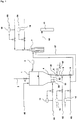
- Fig. 1 shows a schematic of the device according to the invention. From here, a Brennstaubzu operation 2 in the metering 1. From the distributor plate 4 of the metering 1, the Dichtstromdeemtechnischen 51 to 54 extend to the burners (not shown separately) of a multi-channel burner 7. A gas inlet 61 to the distributor plate 4 is used to introduce a fluidizing gas. The gas delivery lines 62 and 63 each open via a Zumischvorraum 9 in the dense flow conveying line 51.
- the Dichtstrom complicatsysteme 51 to 54 are each designed analogously, for clarity is in Fig. 1 however, only the dense flow conveying line 51 is shown completely with admixing devices 9 and dust flow control device 8.
- the other dense flow conveyor lines have according to the dense flow conveyor lines 51 Staubstromregelorgan and Zumischvorraumen.
- the dust control device 8 is provided with an additional, fed back into the dense flow conveying line 51 Flow regulator 10 'connected.
- the additional flow regulator 10 for the dust control device 8 is omitted (the dashed arrows indicate this), when the gas delivery line 63 opens into parallel to the dense flow conveyor lines 51 extending dashed fuel gas delivery line 67, which leads to a feed opening of the dense current conveying lines 51 associated burner.
- the scheme The admixing of fuel gas into the respective dense flow conveying line 51 to 54 from the delivery line 62 or 63 takes place via at least one of the admixing devices 9.
- an admixing of inert gas via a delivery line can take place 62 or 63 take place by means of admixing device 9.
- a mixture of fuel and inert gas in a delivery line is conceivable.
- the supply of fuel gas can also take place via the fluidizing gas line 61 to the distributor plate, whereby the fuel dust in the metering vessel 1 is placed in the flow state.
- an inert gas is used as the fluidizing gas.
- a synthesis gas delivery line 68 leads into a downstream process stage 11.
- the incremental increase in the amount of syngas generated upon startup of a gasification reactor equipped with, for example, four burners (not shown figuratively) in optimally minimized stages by the controller the combustible dust and fuel gas load is such that upon ignition of the first burner, the increase in combustion load associated with the second, third and fourth burners in conjunction with the change in the first, second and third compositions of the fuel blends are previously in operation Burners takes place.
- either the amount of fuel dust or the amount of fuel gas fed into the dense phase conveying line can be used for the regulation.
- a fuel mixture is provided with a first composition of combustible dust and fuel gas which is ignited at a first burner of a gasification reactor having a plurality of burners in a lower load range of the burner of up to 30% of the burner maximum load.
- the ignition of a second burner takes place in its lower load range, which is charged with a second composition of the fuel mixture of fuel dust and fuel.
- the ignition of the second burner automatically triggers the control to change the first composition of the fuel mixture, so that the fuel load added by the ignition of the second burner is absorbed by changing the first composition.
- the fuel gas content in the first composition may be reduced so that the load increase from first ignition to second ignition may be adjusted.
- the ignition of a third or further "nth” burner runs.
- the ignition of the third burner in its lower load range which in turn with a third composition of the fuel mixture of fuel dust and gas is supplied, a change in the second composition of the fuel mixture of the previously fired second burner is controlled.
- the ignition of an "nth" burner in its lower load range which is fed with an “nth” composition of the fuel dust and fuel gas fuel mixture, will cause the (n-1) th composition of a previously ignited (n-1) -ter burner is changed regulated.
Priority Applications (1)
| Application Number | Priority Date | Filing Date | Title |
|---|---|---|---|
| PL09777194T PL2310477T3 (pl) | 2008-08-01 | 2009-07-15 | Sposób i urządzenie do rozruchu reaktorów gazyfikacyjnych zasilanych paliwem pyłowym |
Applications Claiming Priority (2)
| Application Number | Priority Date | Filing Date | Title |
|---|---|---|---|
| DE102008036058A DE102008036058B4 (de) | 2008-08-01 | 2008-08-01 | Verfahren und Vorrichtung zum Anfahren von mit Brennstaub betriebenen Vergasungsreaktoren |
| PCT/EP2009/005125 WO2010012376A2 (de) | 2008-08-01 | 2009-07-15 | Verfahren und vorrichtung zum anfahren von mit brennstaub betriebenen vergasungsreaktoren |
Publications (2)
| Publication Number | Publication Date |
|---|---|
| EP2310477A2 EP2310477A2 (de) | 2011-04-20 |
| EP2310477B1 true EP2310477B1 (de) | 2017-06-21 |
Family
ID=41461613
Family Applications (1)
| Application Number | Title | Priority Date | Filing Date |
|---|---|---|---|
| EP09777194.3A Active EP2310477B1 (de) | 2008-08-01 | 2009-07-15 | Verfahren und vorrichtung zum anfahren von mit brennstaub betriebenen vergasungsreaktoren |
Country Status (12)
| Country | Link |
|---|---|
| US (1) | US9670428B2 (ko) |
| EP (1) | EP2310477B1 (ko) |
| JP (1) | JP2011529970A (ko) |
| KR (1) | KR101643969B1 (ko) |
| CN (1) | CN102105567B (ko) |
| AU (1) | AU2009275490B2 (ko) |
| BR (1) | BRPI0917423A2 (ko) |
| CA (1) | CA2732029C (ko) |
| DE (1) | DE102008036058B4 (ko) |
| PL (1) | PL2310477T3 (ko) |
| RU (1) | RU2011104148A (ko) |
| WO (1) | WO2010012376A2 (ko) |
Families Citing this family (7)
| Publication number | Priority date | Publication date | Assignee | Title |
|---|---|---|---|---|
| DE102009048931B4 (de) * | 2009-10-10 | 2014-06-18 | Linde Ag | Dosieranlage, Dichtstromförderanlage und Verfahren zum Zuführen von staubförmigem Schüttgut |
| DE102011077911A1 (de) * | 2011-06-21 | 2012-12-27 | Siemens Ag | Vergleichmäßigte Einspeisung von Stäuben mit steuerbarer Drosselstelle in der Staubförderleitung |
| US10041667B2 (en) | 2011-09-22 | 2018-08-07 | Ensyn Renewables, Inc. | Apparatuses for controlling heat for rapid thermal processing of carbonaceous material and methods for the same |
| DE102011083850A1 (de) * | 2011-09-30 | 2013-04-04 | Siemens Aktiengesellschaft | Pneumatische Brennstoffzuführung von einem Dosiergefäß zu einem Vergasungsreaktor mit hohem Differenzdruck |
| JP6695163B2 (ja) * | 2016-02-17 | 2020-05-20 | 三菱日立パワーシステムズ株式会社 | 微粉燃料供給装置及び方法、ガス化複合発電設備 |
| PL429573A1 (pl) * | 2016-06-08 | 2019-10-07 | Gas Technology Institute | Sposoby i urządzenia do równomiernego rozprowadzania stałych materiałów paliwowych |
| CN109852425B (zh) * | 2019-01-08 | 2020-11-13 | 科林未来能源技术(北京)有限公司 | 一种气化装置内循环冷却的系统 |
Family Cites Families (17)
| Publication number | Priority date | Publication date | Assignee | Title |
|---|---|---|---|---|
| DE2902911A1 (de) * | 1979-01-26 | 1980-07-31 | Krupp Gmbh | Verfahren und vorrichtung zur pneumatisch in abhaengigkeit der abgefuehrten foerdergutmenge steuerbaren beschickung eines reaktors |
| DE3104054A1 (de) * | 1981-02-06 | 1982-08-12 | Kümmel, Joachim, Dipl.-Ing., 4044 Kaarst | Brenner zur verbrennung von staubfoermigen brennstoffen |
| JPS58104833A (ja) * | 1981-12-12 | 1983-06-22 | Kawasaki Steel Corp | 1個の粉粒体分配輸送タンクから粉粒体を複数供給端に質量流量を任意の設定値に制御して連続供給する方法及びその装置 |
| DD223613A3 (de) * | 1982-06-09 | 1985-06-12 | Freiberg Brennstoffinst | Verfahren zur vergasung/verbrennung staubfoermiger brennstoffe |
| DD205452A1 (de) * | 1982-06-09 | 1983-12-28 | Jens Lahr | Verfahren und vorrichtung zur zufuehrung staubfoermiger materialien in reaktionsgefaesse |
| JPH083104B2 (ja) * | 1986-11-27 | 1996-01-17 | バブコツク日立株式会社 | 石炭ガス化炉用バ−ナ装置 |
| DE3864355D1 (de) * | 1987-09-18 | 1991-09-26 | Shell Int Research | Beschickungsvorrichtung fuer die kohlevergasung. |
| US4830545A (en) | 1987-09-18 | 1989-05-16 | Shell Oil Company | Feed line design |
| CN1017873B (zh) * | 1987-09-18 | 1992-08-19 | 国际壳牌研究有限公司 | 煤气化器的进料装置 |
| DE3823773A1 (de) * | 1988-07-14 | 1990-01-18 | Krupp Koppers Gmbh | Verfahren zur ermittlung und steuerung des brennstoff-massenstromes bei der partialoxidation (vergasung) von feinkoernigen bis staubfoermigen brennstoffen |
| CA2192534C (en) * | 1996-12-10 | 2002-01-29 | Danilo Klvana | Process and apparatus for gas phase exothermic reactions |
| JPH11217574A (ja) * | 1998-01-30 | 1999-08-10 | Nippon Steel Corp | ガス化炉の着火方法及び装置 |
| DE102005047583C5 (de) | 2005-10-04 | 2016-07-07 | Siemens Aktiengesellschaft | Verfahren und Vorrichtung zur geregelten Zufuhr von Brennstaub in einen Flugstromvergaser |
| DE102005048488C5 (de) * | 2005-10-07 | 2020-07-02 | Siemens Aktiengesellschaft | Verfahren und Vorrichtung für Flugstromvergaser hoher Leistung |
| DE102006030079B4 (de) * | 2006-06-28 | 2009-01-22 | Siemens Aktiengesellschaft | Verfahren zur Inbetriebnahme von Flugstrom-Vergasungsreaktoren hoher Leistung mit Kombinationsbrenner und Mehrbrenneranordnung |
| US8303673B2 (en) * | 2006-08-25 | 2012-11-06 | Siemens Aktiengesellschaft | Method and device for a high-capacity entrained flow gasifier |
| JP5166910B2 (ja) * | 2008-01-29 | 2013-03-21 | 三菱重工業株式会社 | 石炭ガス化炉の起動方法および起動装置 |
-
2008
- 2008-08-01 DE DE102008036058A patent/DE102008036058B4/de not_active Expired - Fee Related
-
2009
- 2009-07-15 CA CA2732029A patent/CA2732029C/en active Active
- 2009-07-15 WO PCT/EP2009/005125 patent/WO2010012376A2/de active Application Filing
- 2009-07-15 BR BRPI0917423A patent/BRPI0917423A2/pt not_active IP Right Cessation
- 2009-07-15 AU AU2009275490A patent/AU2009275490B2/en not_active Ceased
- 2009-07-15 RU RU2011104148/05A patent/RU2011104148A/ru not_active Application Discontinuation
- 2009-07-15 PL PL09777194T patent/PL2310477T3/pl unknown
- 2009-07-15 KR KR1020117003507A patent/KR101643969B1/ko active IP Right Grant
- 2009-07-15 US US13/056,337 patent/US9670428B2/en active Active
- 2009-07-15 JP JP2011520352A patent/JP2011529970A/ja active Pending
- 2009-07-15 CN CN200980129271.4A patent/CN102105567B/zh active Active
- 2009-07-15 EP EP09777194.3A patent/EP2310477B1/de active Active
Non-Patent Citations (1)
| Title |
|---|
| None * |
Also Published As
| Publication number | Publication date |
|---|---|
| AU2009275490B2 (en) | 2016-08-18 |
| EP2310477A2 (de) | 2011-04-20 |
| WO2010012376A2 (de) | 2010-02-04 |
| BRPI0917423A2 (pt) | 2015-12-01 |
| KR20110049803A (ko) | 2011-05-12 |
| DE102008036058A1 (de) | 2010-02-04 |
| CN102105567A (zh) | 2011-06-22 |
| CN102105567B (zh) | 2015-03-18 |
| US20110195365A1 (en) | 2011-08-11 |
| CA2732029A1 (en) | 2010-02-04 |
| KR101643969B1 (ko) | 2016-08-01 |
| DE102008036058B4 (de) | 2013-04-18 |
| AU2009275490A1 (en) | 2010-02-04 |
| JP2011529970A (ja) | 2011-12-15 |
| CA2732029C (en) | 2017-09-05 |
| RU2011104148A (ru) | 2012-09-10 |
| US9670428B2 (en) | 2017-06-06 |
| PL2310477T3 (pl) | 2017-12-29 |
| WO2010012376A3 (de) | 2010-06-10 |
Similar Documents
| Publication | Publication Date | Title |
|---|---|---|
| EP2310477B1 (de) | Verfahren und vorrichtung zum anfahren von mit brennstaub betriebenen vergasungsreaktoren | |
| DE102006030079B4 (de) | Verfahren zur Inbetriebnahme von Flugstrom-Vergasungsreaktoren hoher Leistung mit Kombinationsbrenner und Mehrbrenneranordnung | |
| EP2329196B1 (de) | Brenner und verfahren zum betrieb eines brenners | |
| CH697710A2 (de) | Verfahren zum Steuern einer Turbine, die mehrere parallel angeordnete Brennstoffventile hat. | |
| DE102011115363B4 (de) | Kraftwerk und Verfahren für seinen Betrieb | |
| DE102012100261A1 (de) | Stöchiometrische Abgasrückführung und zugehörige Verbrennungssteuerung | |
| EP0484993B1 (de) | Verfahren zum Regeln des Anfahrens einer Vergasung fester Brennstoffe im Wirbelzustand | |
| DE2831027C2 (de) | Verfahren und Vorrichtung zur Flugstromvergasung | |
| CH701150A2 (de) | Verfahren zum Bereitstellen eines mittels eines Plasmabrennersystems reformierten Brennstoffs, der einer oder mehreren Brennkammern in einem Gasturbinensystem zugeführt wird. | |
| DE102014100571A1 (de) | Düsensystem und Verfahren zum Start und Betrieb von Gasturbinen mit niedrigenergetischen Kraftstoffen | |
| DD284041A5 (de) | Verfahren zur ermittlung und steuerung des brennstoff-massenstromes bei der partialoxidation (vergasung) von feinkoernigen bis staubfoermigen brennstoffen | |
| DE102005061486B4 (de) | Verfahren zum Betreiben einer Brennkammer einer Gasturbine | |
| DE3220546C2 (ko) | ||
| DE3047734A1 (de) | Brenner zum vermischen einzelner einsatzstroeme zur bildung eines mehrphasengemisches zur umsetzung in einem partialoxidations-gaserzeuger | |
| AT507175B1 (de) | Verfahren und vorrichtung zur bereitstellung einer konstanten produktgasmenge aus einer wirbelschicht-gaserzeugungsanlage | |
| EP1828572A1 (de) | Verfahren zum betrieb einer gasturbogruppe | |
| DE102018114870B3 (de) | Brennersystem und Verfahren zur Erzeugung von Heißgas in einer Gasturbinenanlage | |
| WO2023057090A1 (de) | Vorrichtung und verfahren zum durchführen einer partiellen oxidation | |
| DE10350039A1 (de) | Brenner für einen Reformer in einem Brennstoffzellensystem | |
| WO2021018535A1 (de) | Vorrichtung und verfahren zum automatisierbaren anfahren einer dampfreformeranordnung in den normalbetriebszustand sowie verwendung sowie steuerungs-/regelungseinrichtung sowie computerprogrammprodukt | |
| DE102004058759A1 (de) | Verfahren zur Bereitstellung eines Brennstoffes für die Gasturbine eines IGCC-Kraftwerkes | |
| DE102004058758A1 (de) | Verfahren zur Regelung des Brenngasstromes für eine Gasturbine in einem IGCC-Kraftwerk | |
| EP2169308A1 (de) | Brennstoffzufuhr und Verfahren zur Brennstoffeindüsung |
Legal Events
| Date | Code | Title | Description |
|---|---|---|---|
| PUAI | Public reference made under article 153(3) epc to a published international application that has entered the european phase |
Free format text: ORIGINAL CODE: 0009012 |
|
| 17P | Request for examination filed |
Effective date: 20110301 |
|
| AK | Designated contracting states |
Kind code of ref document: A2 Designated state(s): AT BE BG CH CY CZ DE DK EE ES FI FR GB GR HR HU IE IS IT LI LT LU LV MC MK MT NL NO PL PT RO SE SI SK SM TR |
|
| AX | Request for extension of the european patent |
Extension state: AL BA RS |
|
| DAX | Request for extension of the european patent (deleted) | ||
| 17Q | First examination report despatched |
Effective date: 20120511 |
|
| 19U | Interruption of proceedings before grant |
Effective date: 20110930 |
|
| 19W | Proceedings resumed before grant after interruption of proceedings |
Effective date: 20121203 |
|
| RAP1 | Party data changed (applicant data changed or rights of an application transferred) |
Owner name: LINDE AG |
|
| 17Q | First examination report despatched |
Effective date: 20130102 |
|
| RAP1 | Party data changed (applicant data changed or rights of an application transferred) |
Owner name: SIEMENS FUEL GASIFICATION TECHNOLOGY GMBH & CO. KG |
|
| RAP1 | Party data changed (applicant data changed or rights of an application transferred) |
Owner name: SIEMENS AKTIENGESELLSCHAFT |
|
| GRAP | Despatch of communication of intention to grant a patent |
Free format text: ORIGINAL CODE: EPIDOSNIGR1 |
|
| RIC1 | Information provided on ipc code assigned before grant |
Ipc: C10J 3/30 20060101AFI20161114BHEP Ipc: C10J 3/50 20060101ALI20161114BHEP Ipc: C10J 3/72 20060101ALI20161114BHEP |
|
| INTG | Intention to grant announced |
Effective date: 20161220 |
|
| GRAJ | Information related to disapproval of communication of intention to grant by the applicant or resumption of examination proceedings by the epo deleted |
Free format text: ORIGINAL CODE: EPIDOSDIGR1 |
|
| INTC | Intention to grant announced (deleted) | ||
| GRAR | Information related to intention to grant a patent recorded |
Free format text: ORIGINAL CODE: EPIDOSNIGR71 |
|
| GRAS | Grant fee paid |
Free format text: ORIGINAL CODE: EPIDOSNIGR3 |
|
| GRAA | (expected) grant |
Free format text: ORIGINAL CODE: 0009210 |
|
| AK | Designated contracting states |
Kind code of ref document: B1 Designated state(s): AT BE BG CH CY CZ DE DK EE ES FI FR GB GR HR HU IE IS IT LI LT LU LV MC MK MT NL NO PL PT RO SE SI SK SM TR |
|
| INTG | Intention to grant announced |
Effective date: 20170515 |
|
| REG | Reference to a national code |
Ref country code: GB Ref legal event code: FG4D Free format text: NOT ENGLISH |
|
| REG | Reference to a national code |
Ref country code: CH Ref legal event code: EP |
|
| REG | Reference to a national code |
Ref country code: IE Ref legal event code: FG4D Free format text: LANGUAGE OF EP DOCUMENT: GERMAN |
|
| REG | Reference to a national code |
Ref country code: AT Ref legal event code: REF Ref document number: 902943 Country of ref document: AT Kind code of ref document: T Effective date: 20170715 |
|
| REG | Reference to a national code |
Ref country code: DE Ref legal event code: R096 Ref document number: 502009014100 Country of ref document: DE |
|
| RAP2 | Party data changed (patent owner data changed or rights of a patent transferred) |
Owner name: SIEMENS AKTIENGESELLSCHAFT |
|
| REG | Reference to a national code |
Ref country code: NL Ref legal event code: FP |
|
| REG | Reference to a national code |
Ref country code: CH Ref legal event code: NV Representative=s name: SIEMENS SCHWEIZ AG, CH Ref country code: CH Ref legal event code: PCOW Free format text: NEW ADDRESS: WERNER-VON-SIEMENS-STRASSE 1, 80333 MUENCHEN (DE) |
|
| PG25 | Lapsed in a contracting state [announced via postgrant information from national office to epo] |
Ref country code: NO Free format text: LAPSE BECAUSE OF FAILURE TO SUBMIT A TRANSLATION OF THE DESCRIPTION OR TO PAY THE FEE WITHIN THE PRESCRIBED TIME-LIMIT Effective date: 20170921 Ref country code: GR Free format text: LAPSE BECAUSE OF FAILURE TO SUBMIT A TRANSLATION OF THE DESCRIPTION OR TO PAY THE FEE WITHIN THE PRESCRIBED TIME-LIMIT Effective date: 20170922 Ref country code: HR Free format text: LAPSE BECAUSE OF FAILURE TO SUBMIT A TRANSLATION OF THE DESCRIPTION OR TO PAY THE FEE WITHIN THE PRESCRIBED TIME-LIMIT Effective date: 20170621 Ref country code: LT Free format text: LAPSE BECAUSE OF FAILURE TO SUBMIT A TRANSLATION OF THE DESCRIPTION OR TO PAY THE FEE WITHIN THE PRESCRIBED TIME-LIMIT Effective date: 20170621 Ref country code: FI Free format text: LAPSE BECAUSE OF FAILURE TO SUBMIT A TRANSLATION OF THE DESCRIPTION OR TO PAY THE FEE WITHIN THE PRESCRIBED TIME-LIMIT Effective date: 20170621 |
|
| REG | Reference to a national code |
Ref country code: LT Ref legal event code: MG4D |
|
| PG25 | Lapsed in a contracting state [announced via postgrant information from national office to epo] |
Ref country code: BG Free format text: LAPSE BECAUSE OF FAILURE TO SUBMIT A TRANSLATION OF THE DESCRIPTION OR TO PAY THE FEE WITHIN THE PRESCRIBED TIME-LIMIT Effective date: 20170921 Ref country code: LV Free format text: LAPSE BECAUSE OF FAILURE TO SUBMIT A TRANSLATION OF THE DESCRIPTION OR TO PAY THE FEE WITHIN THE PRESCRIBED TIME-LIMIT Effective date: 20170621 Ref country code: SE Free format text: LAPSE BECAUSE OF FAILURE TO SUBMIT A TRANSLATION OF THE DESCRIPTION OR TO PAY THE FEE WITHIN THE PRESCRIBED TIME-LIMIT Effective date: 20170621 |
|
| PG25 | Lapsed in a contracting state [announced via postgrant information from national office to epo] |
Ref country code: SK Free format text: LAPSE BECAUSE OF FAILURE TO SUBMIT A TRANSLATION OF THE DESCRIPTION OR TO PAY THE FEE WITHIN THE PRESCRIBED TIME-LIMIT Effective date: 20170621 Ref country code: CZ Free format text: LAPSE BECAUSE OF FAILURE TO SUBMIT A TRANSLATION OF THE DESCRIPTION OR TO PAY THE FEE WITHIN THE PRESCRIBED TIME-LIMIT Effective date: 20170621 Ref country code: EE Free format text: LAPSE BECAUSE OF FAILURE TO SUBMIT A TRANSLATION OF THE DESCRIPTION OR TO PAY THE FEE WITHIN THE PRESCRIBED TIME-LIMIT Effective date: 20170621 Ref country code: RO Free format text: LAPSE BECAUSE OF FAILURE TO SUBMIT A TRANSLATION OF THE DESCRIPTION OR TO PAY THE FEE WITHIN THE PRESCRIBED TIME-LIMIT Effective date: 20170621 |
|
| REG | Reference to a national code |
Ref country code: DE Ref legal event code: R119 Ref document number: 502009014100 Country of ref document: DE |
|
| PG25 | Lapsed in a contracting state [announced via postgrant information from national office to epo] |
Ref country code: SM Free format text: LAPSE BECAUSE OF FAILURE TO SUBMIT A TRANSLATION OF THE DESCRIPTION OR TO PAY THE FEE WITHIN THE PRESCRIBED TIME-LIMIT Effective date: 20170621 Ref country code: IT Free format text: LAPSE BECAUSE OF FAILURE TO SUBMIT A TRANSLATION OF THE DESCRIPTION OR TO PAY THE FEE WITHIN THE PRESCRIBED TIME-LIMIT Effective date: 20170621 Ref country code: IS Free format text: LAPSE BECAUSE OF FAILURE TO SUBMIT A TRANSLATION OF THE DESCRIPTION OR TO PAY THE FEE WITHIN THE PRESCRIBED TIME-LIMIT Effective date: 20171021 Ref country code: ES Free format text: LAPSE BECAUSE OF FAILURE TO SUBMIT A TRANSLATION OF THE DESCRIPTION OR TO PAY THE FEE WITHIN THE PRESCRIBED TIME-LIMIT Effective date: 20170621 |
|
| REG | Reference to a national code |
Ref country code: CH Ref legal event code: PL |
|
| PG25 | Lapsed in a contracting state [announced via postgrant information from national office to epo] |
Ref country code: MC Free format text: LAPSE BECAUSE OF FAILURE TO SUBMIT A TRANSLATION OF THE DESCRIPTION OR TO PAY THE FEE WITHIN THE PRESCRIBED TIME-LIMIT Effective date: 20170621 |
|
| REG | Reference to a national code |
Ref country code: IE Ref legal event code: MM4A |
|
| PLBE | No opposition filed within time limit |
Free format text: ORIGINAL CODE: 0009261 |
|
| REG | Reference to a national code |
Ref country code: FR Ref legal event code: ST Effective date: 20180330 |
|
| STAA | Information on the status of an ep patent application or granted ep patent |
Free format text: STATUS: NO OPPOSITION FILED WITHIN TIME LIMIT |
|
| PG25 | Lapsed in a contracting state [announced via postgrant information from national office to epo] |
Ref country code: IE Free format text: LAPSE BECAUSE OF NON-PAYMENT OF DUE FEES Effective date: 20170715 Ref country code: DE Free format text: LAPSE BECAUSE OF NON-PAYMENT OF DUE FEES Effective date: 20180201 Ref country code: CH Free format text: LAPSE BECAUSE OF NON-PAYMENT OF DUE FEES Effective date: 20170731 Ref country code: LI Free format text: LAPSE BECAUSE OF NON-PAYMENT OF DUE FEES Effective date: 20170731 Ref country code: DK Free format text: LAPSE BECAUSE OF FAILURE TO SUBMIT A TRANSLATION OF THE DESCRIPTION OR TO PAY THE FEE WITHIN THE PRESCRIBED TIME-LIMIT Effective date: 20170621 |
|
| GBPC | Gb: european patent ceased through non-payment of renewal fee |
Effective date: 20170921 |
|
| 26N | No opposition filed |
Effective date: 20180322 |
|
| PG25 | Lapsed in a contracting state [announced via postgrant information from national office to epo] |
Ref country code: FR Free format text: LAPSE BECAUSE OF NON-PAYMENT OF DUE FEES Effective date: 20170821 |
|
| REG | Reference to a national code |
Ref country code: BE Ref legal event code: MM Effective date: 20170731 |
|
| PG25 | Lapsed in a contracting state [announced via postgrant information from national office to epo] |
Ref country code: LU Free format text: LAPSE BECAUSE OF NON-PAYMENT OF DUE FEES Effective date: 20170715 |
|
| PG25 | Lapsed in a contracting state [announced via postgrant information from national office to epo] |
Ref country code: GB Free format text: LAPSE BECAUSE OF NON-PAYMENT OF DUE FEES Effective date: 20170921 |
|
| PG25 | Lapsed in a contracting state [announced via postgrant information from national office to epo] |
Ref country code: BE Free format text: LAPSE BECAUSE OF NON-PAYMENT OF DUE FEES Effective date: 20170731 Ref country code: SI Free format text: LAPSE BECAUSE OF FAILURE TO SUBMIT A TRANSLATION OF THE DESCRIPTION OR TO PAY THE FEE WITHIN THE PRESCRIBED TIME-LIMIT Effective date: 20170621 |
|
| REG | Reference to a national code |
Ref country code: AT Ref legal event code: MM01 Ref document number: 902943 Country of ref document: AT Kind code of ref document: T Effective date: 20170715 |
|
| PG25 | Lapsed in a contracting state [announced via postgrant information from national office to epo] |
Ref country code: MT Free format text: LAPSE BECAUSE OF FAILURE TO SUBMIT A TRANSLATION OF THE DESCRIPTION OR TO PAY THE FEE WITHIN THE PRESCRIBED TIME-LIMIT Effective date: 20170621 |
|
| PG25 | Lapsed in a contracting state [announced via postgrant information from national office to epo] |
Ref country code: AT Free format text: LAPSE BECAUSE OF NON-PAYMENT OF DUE FEES Effective date: 20170715 |
|
| PG25 | Lapsed in a contracting state [announced via postgrant information from national office to epo] |
Ref country code: HU Free format text: LAPSE BECAUSE OF FAILURE TO SUBMIT A TRANSLATION OF THE DESCRIPTION OR TO PAY THE FEE WITHIN THE PRESCRIBED TIME-LIMIT; INVALID AB INITIO Effective date: 20090715 |
|
| PG25 | Lapsed in a contracting state [announced via postgrant information from national office to epo] |
Ref country code: CY Free format text: LAPSE BECAUSE OF NON-PAYMENT OF DUE FEES Effective date: 20170621 |
|
| PG25 | Lapsed in a contracting state [announced via postgrant information from national office to epo] |
Ref country code: MK Free format text: LAPSE BECAUSE OF FAILURE TO SUBMIT A TRANSLATION OF THE DESCRIPTION OR TO PAY THE FEE WITHIN THE PRESCRIBED TIME-LIMIT Effective date: 20170621 |
|
| PG25 | Lapsed in a contracting state [announced via postgrant information from national office to epo] |
Ref country code: TR Free format text: LAPSE BECAUSE OF FAILURE TO SUBMIT A TRANSLATION OF THE DESCRIPTION OR TO PAY THE FEE WITHIN THE PRESCRIBED TIME-LIMIT Effective date: 20170621 |
|
| PG25 | Lapsed in a contracting state [announced via postgrant information from national office to epo] |
Ref country code: PT Free format text: LAPSE BECAUSE OF FAILURE TO SUBMIT A TRANSLATION OF THE DESCRIPTION OR TO PAY THE FEE WITHIN THE PRESCRIBED TIME-LIMIT Effective date: 20170621 |
|
| PGFP | Annual fee paid to national office [announced via postgrant information from national office to epo] |
Ref country code: NL Payment date: 20220711 Year of fee payment: 14 |
|
| PGFP | Annual fee paid to national office [announced via postgrant information from national office to epo] |
Ref country code: PL Payment date: 20220711 Year of fee payment: 14 |
|
| REG | Reference to a national code |
Ref country code: NL Ref legal event code: PD Owner name: SIEMENS ENERGY GLOBAL GMBH & CO. KG; DE Free format text: DETAILS ASSIGNMENT: CHANGE OF OWNER(S), ASSIGNMENT; FORMER OWNER NAME: SIEMENS AKTIENGESELLSCHAFT Effective date: 20221220 |
|
| REG | Reference to a national code |
Ref country code: NL Ref legal event code: MM Effective date: 20230801 |
|
| PG25 | Lapsed in a contracting state [announced via postgrant information from national office to epo] |
Ref country code: NL Free format text: LAPSE BECAUSE OF NON-PAYMENT OF DUE FEES Effective date: 20230801 |
|
| PG25 | Lapsed in a contracting state [announced via postgrant information from national office to epo] |
Ref country code: NL Free format text: LAPSE BECAUSE OF NON-PAYMENT OF DUE FEES Effective date: 20230801 |