EP2306122A1 - Kälteprozessvorrichtung und klimaanlage - Google Patents
Kälteprozessvorrichtung und klimaanlage Download PDFInfo
- Publication number
- EP2306122A1 EP2306122A1 EP09770030A EP09770030A EP2306122A1 EP 2306122 A1 EP2306122 A1 EP 2306122A1 EP 09770030 A EP09770030 A EP 09770030A EP 09770030 A EP09770030 A EP 09770030A EP 2306122 A1 EP2306122 A1 EP 2306122A1
- Authority
- EP
- European Patent Office
- Prior art keywords
- refrigerant
- pressure
- control means
- refrigerating cycle
- compressor
- Prior art date
- Legal status (The legal status is an assumption and is not a legal conclusion. Google has not performed a legal analysis and makes no representation as to the accuracy of the status listed.)
- Granted
Links
Images


Classifications
-
- F—MECHANICAL ENGINEERING; LIGHTING; HEATING; WEAPONS; BLASTING
- F25—REFRIGERATION OR COOLING; COMBINED HEATING AND REFRIGERATION SYSTEMS; HEAT PUMP SYSTEMS; MANUFACTURE OR STORAGE OF ICE; LIQUEFACTION SOLIDIFICATION OF GASES
- F25B—REFRIGERATION MACHINES, PLANTS OR SYSTEMS; COMBINED HEATING AND REFRIGERATION SYSTEMS; HEAT PUMP SYSTEMS
- F25B49/00—Arrangement or mounting of control or safety devices
- F25B49/005—Arrangement or mounting of control or safety devices of safety devices
-
- C—CHEMISTRY; METALLURGY
- C09—DYES; PAINTS; POLISHES; NATURAL RESINS; ADHESIVES; COMPOSITIONS NOT OTHERWISE PROVIDED FOR; APPLICATIONS OF MATERIALS NOT OTHERWISE PROVIDED FOR
- C09K—MATERIALS FOR MISCELLANEOUS APPLICATIONS, NOT PROVIDED FOR ELSEWHERE
- C09K5/00—Heat-transfer, heat-exchange or heat-storage materials, e.g. refrigerants; Materials for the production of heat or cold by chemical reactions other than by combustion
- C09K5/02—Materials undergoing a change of physical state when used
- C09K5/04—Materials undergoing a change of physical state when used the change of state being from liquid to vapour or vice versa
- C09K5/041—Materials undergoing a change of physical state when used the change of state being from liquid to vapour or vice versa for compression-type refrigeration systems
- C09K5/044—Materials undergoing a change of physical state when used the change of state being from liquid to vapour or vice versa for compression-type refrigeration systems comprising halogenated compounds
- C09K5/045—Materials undergoing a change of physical state when used the change of state being from liquid to vapour or vice versa for compression-type refrigeration systems comprising halogenated compounds containing only fluorine as halogen
-
- C—CHEMISTRY; METALLURGY
- C09—DYES; PAINTS; POLISHES; NATURAL RESINS; ADHESIVES; COMPOSITIONS NOT OTHERWISE PROVIDED FOR; APPLICATIONS OF MATERIALS NOT OTHERWISE PROVIDED FOR
- C09K—MATERIALS FOR MISCELLANEOUS APPLICATIONS, NOT PROVIDED FOR ELSEWHERE
- C09K2205/00—Aspects relating to compounds used in compression type refrigeration systems
- C09K2205/10—Components
- C09K2205/12—Hydrocarbons
- C09K2205/126—Unsaturated fluorinated hydrocarbons
-
- F—MECHANICAL ENGINEERING; LIGHTING; HEATING; WEAPONS; BLASTING
- F25—REFRIGERATION OR COOLING; COMBINED HEATING AND REFRIGERATION SYSTEMS; HEAT PUMP SYSTEMS; MANUFACTURE OR STORAGE OF ICE; LIQUEFACTION SOLIDIFICATION OF GASES
- F25B—REFRIGERATION MACHINES, PLANTS OR SYSTEMS; COMBINED HEATING AND REFRIGERATION SYSTEMS; HEAT PUMP SYSTEMS
- F25B13/00—Compression machines, plants or systems, with reversible cycle
-
- F—MECHANICAL ENGINEERING; LIGHTING; HEATING; WEAPONS; BLASTING
- F25—REFRIGERATION OR COOLING; COMBINED HEATING AND REFRIGERATION SYSTEMS; HEAT PUMP SYSTEMS; MANUFACTURE OR STORAGE OF ICE; LIQUEFACTION SOLIDIFICATION OF GASES
- F25B—REFRIGERATION MACHINES, PLANTS OR SYSTEMS; COMBINED HEATING AND REFRIGERATION SYSTEMS; HEAT PUMP SYSTEMS
- F25B2313/00—Compression machines, plants or systems with reversible cycle not otherwise provided for
- F25B2313/027—Compression machines, plants or systems with reversible cycle not otherwise provided for characterised by the reversing means
- F25B2313/02741—Compression machines, plants or systems with reversible cycle not otherwise provided for characterised by the reversing means using one four-way valve
-
- F—MECHANICAL ENGINEERING; LIGHTING; HEATING; WEAPONS; BLASTING
- F25—REFRIGERATION OR COOLING; COMBINED HEATING AND REFRIGERATION SYSTEMS; HEAT PUMP SYSTEMS; MANUFACTURE OR STORAGE OF ICE; LIQUEFACTION SOLIDIFICATION OF GASES
- F25B—REFRIGERATION MACHINES, PLANTS OR SYSTEMS; COMBINED HEATING AND REFRIGERATION SYSTEMS; HEAT PUMP SYSTEMS
- F25B2400/00—General features or devices for refrigeration machines, plants or systems, combined heating and refrigeration systems or heat-pump systems, i.e. not limited to a particular subgroup of F25B
- F25B2400/12—Inflammable refrigerants
- F25B2400/121—Inflammable refrigerants using R1234
-
- F—MECHANICAL ENGINEERING; LIGHTING; HEATING; WEAPONS; BLASTING
- F25—REFRIGERATION OR COOLING; COMBINED HEATING AND REFRIGERATION SYSTEMS; HEAT PUMP SYSTEMS; MANUFACTURE OR STORAGE OF ICE; LIQUEFACTION SOLIDIFICATION OF GASES
- F25B—REFRIGERATION MACHINES, PLANTS OR SYSTEMS; COMBINED HEATING AND REFRIGERATION SYSTEMS; HEAT PUMP SYSTEMS
- F25B2500/00—Problems to be solved
- F25B2500/07—Exceeding a certain pressure value in a refrigeration component or cycle
-
- F—MECHANICAL ENGINEERING; LIGHTING; HEATING; WEAPONS; BLASTING
- F25—REFRIGERATION OR COOLING; COMBINED HEATING AND REFRIGERATION SYSTEMS; HEAT PUMP SYSTEMS; MANUFACTURE OR STORAGE OF ICE; LIQUEFACTION SOLIDIFICATION OF GASES
- F25B—REFRIGERATION MACHINES, PLANTS OR SYSTEMS; COMBINED HEATING AND REFRIGERATION SYSTEMS; HEAT PUMP SYSTEMS
- F25B2500/00—Problems to be solved
- F25B2500/19—Calculation of parameters
-
- F—MECHANICAL ENGINEERING; LIGHTING; HEATING; WEAPONS; BLASTING
- F25—REFRIGERATION OR COOLING; COMBINED HEATING AND REFRIGERATION SYSTEMS; HEAT PUMP SYSTEMS; MANUFACTURE OR STORAGE OF ICE; LIQUEFACTION SOLIDIFICATION OF GASES
- F25B—REFRIGERATION MACHINES, PLANTS OR SYSTEMS; COMBINED HEATING AND REFRIGERATION SYSTEMS; HEAT PUMP SYSTEMS
- F25B2600/00—Control issues
- F25B2600/02—Compressor control
- F25B2600/021—Inverters therefor
-
- F—MECHANICAL ENGINEERING; LIGHTING; HEATING; WEAPONS; BLASTING
- F25—REFRIGERATION OR COOLING; COMBINED HEATING AND REFRIGERATION SYSTEMS; HEAT PUMP SYSTEMS; MANUFACTURE OR STORAGE OF ICE; LIQUEFACTION SOLIDIFICATION OF GASES
- F25B—REFRIGERATION MACHINES, PLANTS OR SYSTEMS; COMBINED HEATING AND REFRIGERATION SYSTEMS; HEAT PUMP SYSTEMS
- F25B2600/00—Control issues
- F25B2600/11—Fan speed control
- F25B2600/111—Fan speed control of condenser fans
-
- F—MECHANICAL ENGINEERING; LIGHTING; HEATING; WEAPONS; BLASTING
- F25—REFRIGERATION OR COOLING; COMBINED HEATING AND REFRIGERATION SYSTEMS; HEAT PUMP SYSTEMS; MANUFACTURE OR STORAGE OF ICE; LIQUEFACTION SOLIDIFICATION OF GASES
- F25B—REFRIGERATION MACHINES, PLANTS OR SYSTEMS; COMBINED HEATING AND REFRIGERATION SYSTEMS; HEAT PUMP SYSTEMS
- F25B2700/00—Sensing or detecting of parameters; Sensors therefor
- F25B2700/19—Pressures
- F25B2700/191—Pressures near an expansion valve
-
- F—MECHANICAL ENGINEERING; LIGHTING; HEATING; WEAPONS; BLASTING
- F25—REFRIGERATION OR COOLING; COMBINED HEATING AND REFRIGERATION SYSTEMS; HEAT PUMP SYSTEMS; MANUFACTURE OR STORAGE OF ICE; LIQUEFACTION SOLIDIFICATION OF GASES
- F25B—REFRIGERATION MACHINES, PLANTS OR SYSTEMS; COMBINED HEATING AND REFRIGERATION SYSTEMS; HEAT PUMP SYSTEMS
- F25B2700/00—Sensing or detecting of parameters; Sensors therefor
- F25B2700/19—Pressures
- F25B2700/193—Pressures of the compressor
- F25B2700/1931—Discharge pressures
-
- F—MECHANICAL ENGINEERING; LIGHTING; HEATING; WEAPONS; BLASTING
- F25—REFRIGERATION OR COOLING; COMBINED HEATING AND REFRIGERATION SYSTEMS; HEAT PUMP SYSTEMS; MANUFACTURE OR STORAGE OF ICE; LIQUEFACTION SOLIDIFICATION OF GASES
- F25B—REFRIGERATION MACHINES, PLANTS OR SYSTEMS; COMBINED HEATING AND REFRIGERATION SYSTEMS; HEAT PUMP SYSTEMS
- F25B2700/00—Sensing or detecting of parameters; Sensors therefor
- F25B2700/21—Temperatures
- F25B2700/2116—Temperatures of a condenser
-
- F—MECHANICAL ENGINEERING; LIGHTING; HEATING; WEAPONS; BLASTING
- F25—REFRIGERATION OR COOLING; COMBINED HEATING AND REFRIGERATION SYSTEMS; HEAT PUMP SYSTEMS; MANUFACTURE OR STORAGE OF ICE; LIQUEFACTION SOLIDIFICATION OF GASES
- F25B—REFRIGERATION MACHINES, PLANTS OR SYSTEMS; COMBINED HEATING AND REFRIGERATION SYSTEMS; HEAT PUMP SYSTEMS
- F25B9/00—Compression machines, plants or systems, in which the refrigerant is air or other gas of low boiling point
- F25B9/002—Compression machines, plants or systems, in which the refrigerant is air or other gas of low boiling point characterised by the refrigerant
Definitions
- the present invention relates to a refrigerating cycle device constituting a refrigerating cycle such as air conditioners including a multi-air conditioner for building, a room-air conditioner, a package air conditioner and the like, a refrigerator and the like.
- a refrigerating cycle device constituting a refrigerating cycle such as air conditioners including a multi-air conditioner for building, a room-air conditioner, a package air conditioner and the like, a refrigerator and the like.
- a refrigerating cycle device using a refrigerating cycle such as an air conditioner, a freezer, a water heater and the like
- a compressor, a condenser (heat exchanger), an expansion valve, and an evaporator (heat exchanger) are connected by piping so as to constitute a refrigerant circuit through which a refrigerant is circulated, for example.
- heating (radiation) and cooling (heat absorption) of a heat-exchange target by the refrigerant in evaporation and condensation an air-conditioning operation, a cooling operation, a heating operation and the like are performed while a pressure inside a pipe is changed.
- single refrigerant such as HCFC-22 (CHClF 2 ) and HFC-134a (CF 3 CH 2 F) and mixed refrigerant such as R-410A, which is a mixture of HFC-32 (CH 2 F 2 ) and HFC-125 (CH 3 CHF 2 ), and R-407C, which is a mixture of HFC-32 (CH 2 F 2 ) and HFC-125 (CF 3 CHF 2 ), and HFC-134a (CF 3 CH 2 F), which are chemically stable substances, are used (See Patent Literature 1, for example).
- a refrigerant having as small global warming coefficient (GWP: a degree of incurring global warming with respect to a substance, which is a greenhouse effect gas, represented by a coefficient determined on the basis of knowledge internationally approved as numeral values indicating a ratio to the degree regarding carbon dioxide) as possible is preferably used.
- GWP small global warming coefficient
- the mixed refrigerant as a whole might stop functioning since it is decomposed and deteriorated by the other refrigerants or decomposes and deteriorates the other refrigerants, and as a result, there is a possibility that the refrigerating cycle device cannot be used normally.
- the present invention was made in order to solve the above problems and has an object to obtain a refrigerating cycle device or the like that can prevent decomposition of the refrigerant and maintain a normal operation for a long time even if a refrigerant containing a chemically unstable substance such as a refrigerant having a double bond is used as a refrigerant to be circulated through a refrigerant circuit.
- a refrigerant circuit is configured by connecting a compressor for compressing a refrigerant containing a substance having a double bond, a condenser for condensing the refrigerant by heat exchange, expanding means for decompressing the condensed refrigerant, and an evaporator for evaporating the decompressed refrigerant by heat exchange by piping and the device is provided with control means for controlling an operation of the refrigerant circuit so that a pressure value of the refrigerant in the refrigerant circuit becomes less than a critical pressure of the substance having the double bond.
- the refrigerating cycle device of the present invention in configuring a refrigerant circuit through which a refrigerant containing a substance having double bond is circulated, since an operation of the refrigerant circuit is controlled so that a pressure value of the refrigerant in the refrigerant circuit becomes less than a critical pressure of the substance having double bond, in the refrigerant containing the substance having chemically unstable double bond, decomposition of the substance itself having double bond due to exceeding of the critical pressure by the substance having double bond or attack on the substance having double bond due to exceeding of the critical pressure of the other substances, which results in non-functioning as the refrigerant, can be effectively suppressed.
- a refrigerating cycle device in which a refrigerant with a smaller global warming coefficient and containing a substance suitable for the environment and having double bond, for example, can be effectively used.
- Fig. 1 is a diagram illustrating a configuration of a refrigerating cycle device according to Embodiment 1 of the present invention.
- the refrigerating cycle device has a compressor 21, a condenser 22, a condenser fan 31, expanding means 23, an evaporator 24, an evaporator fan 32, and pressure detecting means 41.
- a refrigerant circuit is configured by connecting the compressor 21, the condenser 22, the expanding means 23, and the evaporator 24 by piping.
- a mixed refrigerant in which at least one type of refrigerant containing a substance having double bond in atomic bond is mixed is sealed as a refrigerant to become a medium for carrying heat in the refrigerant circuit. The refrigerant will be described later.
- the compressor 21 sucks the refrigerant to be circulated in the refrigerant circuit, compresses it and raises its pressure.
- the compressor 21 any of various types such as reciprocating, rotary, scroll, screw and the like may be used.
- the compressor may be provided with an inverter circuit, for example, that can change a capacity (an amount of the refrigerant to be fed per unit time) by arbitrarily changing a compressor frequency even in a compressor with a fixed compressor frequency.
- the condenser 22 performs heat exchange between a gas state refrigerant (hereinafter referred to as a gas refrigerant) discharged by the compressor 21 and a heat-exchange target (supposing to be air in this Embodiment), emits a heat quantity of the refrigerant to heat the air.
- the condenser fan 31 feeds air to the condenser 22 so as to perform heat exchange with the refrigerant efficiently.
- the expanding means 23 is constituted by an electronic expansion valve, a temperature-type expansion vale, a capillary tube and the like and adjusts a flow rate of the passing refrigerant to lower the pressure of the refrigerant (to decompress).
- the evaporator 24 performs heat exchange between a gas-liquid two-phase refrigerant (a refrigerant in a state in which a gas refrigerant and a liquid-state refrigerant (hereinafter referred to as a liquid refrigerant) are mixed) whose pressure is lowered by the expanding means 23 and the heat-exchange target (supposing to be air, too) so that the refrigerant absorbs the heat quantity and is gasified.
- the air is cooled.
- the evaporator fan 32 is also provided for efficient heat exchange between the air and the refrigerant in the evaporator 24.
- heat exchange with air is performed using the condenser fan 31 and the evaporator fan 32, but heat exchange with water can be performed using a water cooler using a pump and water instead of the condenser fan 23, a device such as a chiller using pump and water or brine instead of the evaporator fan 26 and the like.
- the pressure detecting means 41 which is a pressure sensor, is disposed on the side of a refrigerant outlet (discharge) of the compressor 21, which is a portion with the highest pressure in the refrigerant circuit in this Embodiment and transmits a signal on the basis of a pressure relating to the detection to control means or the like, which will be described later.
- a level of the pressure in the refrigerant circuit is not determined by a relationship with a pressure to be a reference but is indicated as a relative pressure determined by compression of the compressor 21, refrigerant flow-rate control of the expanding means 23 and the like. The same applies to a degree of the temperature.
- a configuration with a single unit of the condenser 22 and a single unit of the evaporator 24 is described as an example, but the number of connection of the condenser 22 and the evaporator 24 in the refrigerant circuit is not limited to one, but a plurality of units can be connected in parallel, for example.
- a configuration with a single unit is also described as an example, but a plurality of compressors 21 can be connected in series or in parallel, for example.
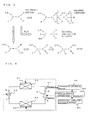
- Fig. 2 is a P-h diagram relating to the refrigerant circuit configured by the refrigerating cycle device in Fig. 1 .
- Pressures and enthalpy at points a, b, c, and d shown in Fig. 2 represent the pressures and enthalpy at the corresponding points in the refrigerating cycle device in Fig. 1 .
- the liquefied refrigerant is fed into the expanding means 23.
- the liquid refrigerant is decompressed while passing through the expanding means 23 so as to become the gas-liquid two-phase refrigerant and is fed into the evaporator 24.
- the gas-liquid two-phase refrigerant having passed through the evaporator 24 is heat-exchanged with the air fed in by the evaporator fan 32 and evaporated and gasified.
- the gasified refrigerant is sucked again by the compressor 21.
- a flow passage of the refrigerant from the compressor 21 to the expanding means 23 is a high-pressure flow passage, which is a flow passage with a relatively high pressure in the refrigerant circuit.
- the pressure Pa of the refrigerant on the outlet side of the compressor 21 is the highest, while the pressure Pb of the refrigerant on the inlet side of the expanding means 23 is slightly lower than Pa due to the pressure loss in the condenser 22 and the connection piping.
- control for keeping the refrigerant pressure in the refrigerant circuit low is performed by constituent means of the refrigerating cycle device, but the refrigerant pressure here is basically supposed to the pressure Pa of the refrigerant on the outlet side of the compressor 21.
- a point where a saturated liquid line meets a saturated gas line is referred to as a critical point, and in a state in which the refrigerant pressure is higher than a pressure at the critical point (hereinafter referred to as a critical pressure. It is a pressure Pcr in Fig. 2 ), the refrigerant is in a supercritical state, which is neither liquid nor gas. If the refrigerant is brought into the supercritical state, it presents a nature different from that in the gas state or liquid state. In the supercritical state, even a substance, which is stable in a usual use, has a nature to decompose, a nature that dissolves various substances well and the like are shown. Such high solubility and reactivity require consideration for materials of a container or a seal in the compressor 21 or the like.
- a mixed refrigerant constituted as a mixture of a plurality of types of refrigerants is considered.
- Mixed refrigerants usually used include R-410A, which is a mixture of HFC-32 and HFC-125, R-407C, which is a mixture of HFC-32, HFC-125, and HFC-134a and the like.
- HFC-32 is CH 2 F 2
- HFC-125 is CH 3 CHF 2
- HFC-134a is CF 3 CH 2 F.
- a refrigerant made of a substance having a double bond might be mixed with other refrigerants.
- HFO hydrofluoroolefin
- a mixed refrigerant in which a plurality of types of refrigerants with smaller global warming coefficients and made of substances having the double bond are mixed may be preferably used, but a refrigerant made of a substance bonded by a single bond such as HFC-32, HFC-125, HFC-134a and the like or other refrigerants can be also mixed.
- the substance having double bond has a chemically unstable nature, and the refrigerant made of such substance has a nature of being easily decomposed in the air, for example, due to an influence of light, ozone and the like.
- the refrigerant made of such substance has a nature of being easily decomposed in the air, for example, due to an influence of light, ozone and the like.
- the single refrigerant made of a substance having double bond or a mixed refrigerant containing the refrigerant made of a substance having double bond is sealed to be used as a refrigerant to be circulated through the refrigerant circuit (working fluid), the double bond is decomposed in the refrigerant circuit, and there is a risk that the refrigerant stops functioning as refrigerant.
- This polymer compound becomes a sludge and circulates with the refrigerant in the refrigerant circuit, which causes valve clogging or the like in the expanding means or the like whose flow passage is narrow, for example.
- the compound might become alcohol presenting acidity in the form of CF 3 CFCOHCH 3 or sludge.
- Moisture in the refrigerant circuit is usually adsorbed and removed by a drier (not shown) or the like.
- the refrigerant having double bond is used as a refrigerant to be circulated in the refrigerant circuit (working fluid), it should be used in a state in which a cause to promote decomposition of the refrigerant such as air, light and the like is removed as much as possible.
- the mixed refrigerant has different natures relating to heat, different refrigerating cycles (P-h diagram), and different critical points depending on constituting refrigerants.
- P-h diagram refrigerating cycles
- each refrigerant repeats condensation and evaporation and circulates in the refrigerant circuit.
- a critical pressure of the refrigerant with the lowest critical point is referred to as the lowest critical pressure.
- the refrigerant circuit through which the mixed refrigerant is circulated if the pressure of the refrigerant (particularly, the pressure on the high-pressure side) is lower than the lowest critical pressure all the time, the refrigerants are not decomposed or the like but circulated in the refrigerant circuit for a long time and is capable of repeated condensation, evaporation and the like. However, if the refrigerant pressure becomes higher than the lowest critical pressure, the refrigerant with a low critical pressure is brought into the supercritical state, and it is circulated in the supercritical state with other refrigerants in the refrigerant circuit.
- the mixed refrigerant constituted only by chemically stable refrigerants such as R-410A and R-407C for example, even if the refrigerant pressure on the high pressure side becomes higher than the lowest critical pressure and a part of the refrigerants is brought into the supercritical state, the mixed refrigerants as a whole is not decomposed but can be used stably.
- the refrigerant in the supercritical state attacks the refrigerant made up of the chemically unstable substance having double bond, and the refrigerant is decomposed and cannot maintain stable properties any longer.
- the mixed refrigerant will not function as a refrigerant at all.
- the refrigerant pressure at all the positions in the refrigerant circuit is controlled so that the pressure is at the lowest critical pressure or less all the time and the mixed refrigerant is circulated so that none of the refrigerants is brought into the supercritical state.
- the refrigerant in the supercritical state also attacks itself.
- the above also applies to a situation in which the critical pressure of the other refrigerants are higher than the refrigerant made up of a substance having the double bond or a situation in which only the refrigerant made up of a substance having the double bond is used as a refrigerant, and if the device is to be operated, control should be made in circulating the refrigerant so that the refrigerant is not turned into the supercritical state.
- a flow passage to become the high pressure side in the refrigerant circuit is a flow passage leading from the compressor 21 to the expanding means 23.
- the pressure on the outlet (discharge) side of the compressor 21 is the highest in the refrigerant circuit.
- the pressure detecting means 41 is disposed on the outlet side of the compressor 21 so as to obtain the refrigerating cycle device controlled so that a pressure on the basis of a signal from the pressure detecting means 41 does not exceed the lowest critical pressure.
- Fig. 4 is a diagram illustrating a configuration of the refrigerating cycle device including a system relating to control of this Embodiment.
- control means 53 executes processing for controlling operations of each means of the refrigerating cycle device.
- the control means functions as high-pressure control means for controlling each means by determining a value of a refrigerant pressure of a portion to become the highest pressure in the refrigerant circuit (hereinafter referred to as a high-pressure pressure value) on the basis of a signal from the pressure detecting means 41 and executing processing such as calculation.
- Pressure storage means 51 stores data of a plurality of high-pressure pressure values per predetermined interval for a past predetermined period of time.
- the critical pressure storage means 52 is means for storing a pressure value set on the basis of the lowest critical pressure mentioned in the mixed refrigerant.
- the means stores two values, that is, a first pressure value and a second pressure value.
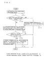
- Fig. 5 is a diagram illustrating a flowchart of pressure control executed by the control means 53.
- the control means 53 determines a high-pressure pressure value (ST1) and has it stored in the pressure storage means 51.
- control means 53 compares the high-pressure pressure value with the first pressure value stored in the critical pressure storage means 52 (ST2).
- the first pressure value a value obtained by subtracting a predetermined value ⁇ to become a margin from a value of the lowest critical pressure is set as the first pressure value so that it becomes less than the critical pressure having double bond, for example, considering a detection error of pressure contained in the high-pressure pressure value, a refrigerant pressure inside the compressor 21 and the like.
- the first pressure value is a value lower than the lowest critical pressure.
- a value of the predetermined value ⁇ can be determined arbitrarily but here, it is supposed to be 0.2 (MPa).
- the control means 53 controls the compressor 21 so as to rapidly lower the refrigerant pressure on the high pressure side of the refrigerant circuit (ST3) so that the refrigerant is not decomposed.
- the control of the compressor 21 includes rapid lowering of a compressor frequency if the compressor 21 is a compressor having an inverter circuit, for example. Alternatively, if the compressor 21 is a compressor with a fixed compressor frequency, its operation is temporarily stopped.
- a forecast value of a pressure after a predetermined time is calculated (ST4).
- a variation with time (trend) is derived from a plurality of high-pressure pressure values using a method as a three-point forecast method or the like, and a pressure value after a predetermined time is calculated as a forecast value.
- the control means 53 may calculate the forecast value not only by the three-point forecast method but also by other methods.
- the control means 53 compares the calculated forecast value and the second pressure value stored in the critical pressure storage means 52 (ST5).
- the second pressure value a value obtained by subtracting a predetermined value ⁇ to become a margin from a value of the lowest critical pressure is set as the second pressure value, considering a detection error of a pressure included in the high-pressure pressure value or the like.
- the second pressure value is also a value lower than the lowest critical pressure.
- a value of the predetermined value ⁇ can be determined arbitrarily, but it is supposed to be 0.5 (MPa), here.
- the first pressure value is made different from the second pressure value, but they may be the same. Alternatively, only one of comparison between the high-pressure pressure value and the first pressure value and comparison between the forecast value and the second pressure value can be made.
- the control means 53 controls operations of one or more means of the compressor 21, the condenser fan 31, the evaporator fan 32, and the expanding means 23 of the refrigerating cycle device.
- the refrigerant pressure on the high-pressure side of the refrigerant circuit is lowered so that the pressure does not exceed the lowest critical pressure and the refrigerant is not decomposed.
- the compressor 21 is a compressor having an inverter circuit, for example, the compressor frequency is lowered by a predetermined amount (10 Hz, for example).
- a heat quantity of the refrigerant in the condenser 22 is emitted by increasing the rotation number of the fan.
- an opening degree is increased and the pressure on the high pressure side is lowered.
- the evaporator fan 32 the rotation number of the fan is decreased, and absorption of the heat quantity by the refrigerant in the evaporator 24 is suppressed.
- the control means 53 repeats the above processing and controls each means of the refrigerating cycle device so that even one type of the refrigerants constituting the mixed refrigerant circulating in the refrigerant circuit is not decomposed or the like.
- pressure loss from the outlet of the compressor 21 to the condenser 22 or the expanding means 23 can be calculated from a piping diameter, a piping length, a refrigerant flow-rate and the like, for example.
- a pressure at the outlet of the compressor 21 can be estimated and calculated easily from a refrigerant pressure value relating to detection at the position.
- the pressure detecting means 41 a pressure sensor of a semiconductor type or a strain gauge type for performing signal transmission according to a detected pressure is generally used.
- the pressure detecting means 41 is not limited to these types of pressure sensor but a pressure sensor outputting an ON signal at a predetermined pressure may be used, for example. In this case, the control means 53 does not have to determine the high-pressure pressure value.
- a pressure switch a value slightly lower than the lowest critical pressure is set as a predetermined pressure in the pressure switch, and wiring is laid so that a compression operation of the compressor 21 is stopped by an ON signal outputted by the pressure switch at the predetermined pressure.
- the pressure storage means 51, the critical pressure storage means 52, and the control means 53 as high-pressure control means in this Embodiment are not necessary any more, and an inexpensive control system can be configured.
- the compressor 21 repeats start and stop in the vicinity of the lowest critical pressure. Thus, there is a possibility that cooling capacity or heating capacity cannot be fully exerted, and the pressure sensor is preferably used.
- temperature detecting means such as a temperature sensor or the like for detecting a condensation temperature may be installed close to the center of the condenser 22 instead of the pressure detecting means 41, for example, so that a refrigerant pressure on the high pressure side is calculated on the basis of a condensation temperature.
- the refrigerant needs to be in a gas-liquid two-phase state at a position where the temperature detecting means is installed, basically, and if the means are installed at plural locations, detection accuracy of the condensation temperature can be improved, by which detection accuracy of the pressure can be also improved.
- the refrigerant containing a chemically unstable substance having double bond can be prevented from being attacked by decomposition of the substance itself having double bond or decomposition of substances of the other refrigerants in the mixed refrigerant and decomposed so as to stop functioning as a refrigerant. Therefore, performances of the refrigerating cycle device can be maintained for a long time, and reliability can be also ensured.
- the pressure can be lowered by other means, but in order to lower the pressure on the outlet side of the compressor 21, it is most effective to rapidly lower the compressor frequency of the compressor 21 or to stop the compressor 21.
- the HFO refrigerant such as tetrafluoropropylene or the like used as refrigerant at this time has a global warming coefficient equivalent to that of carbon dioxide, which is a natural refrigerant, for example, and this is preferable in terms of the environment.
- the forecast value of the refrigerant pressure on the outlet side of the compressor 21 after a predetermined time is calculated by a three-point forecast method or the like, for example, on the basis of data of the high-pressure pressure value for a past predetermined period of time relating to detection of the pressure detecting means 41 and if the value is determined to be larger than the second pressure value, the refrigerant pressure is lowered by control, a trend of the refrigerant pressure can be determined so that the trend is responded according to the determination and the pressure does not exceed the lowest critical pressure, and the refrigerant can be prevented from being decomposed. Also, by controlling one or more in combination of the condenser fan 31, the evaporation fan 32 and the like, the refrigerant pressure on the outlet side of the compressor 21 can be effectively lowered.
- Fig. 6 is a diagram illustrating a configuration of an air conditioner according to Embodiment 2 of the present invention.
- an air conditioner such as a multi air conditioner for building will be described as a typical example of the refrigerating cycle device in Embodiment 1.
- means and the like given the same reference numerals as those in Fig. 1 are means basically performing the same operations as the operations described above.
- the control means 53 in this Embodiment executes control for controlling operations of each means (particularly means on the side of an outdoor unit 60) of the refrigerating cycle device on the basis of an operation state of indoor units 61a and 61b.
- the air conditioner in Fig. 6 has the single outdoor unit 60 and two indoor units 61a and 61b.
- the outdoor unit 60 has the compressor 21, an outdoor heat exchanger 25, a four-way valve 27, an accumulator 28, an outdoor heat exchanger fan 33, and the pressure detecting means 41.
- the indoor units 61a and 61b have expanding means 23a and 23b, indoor heat exchangers 26a and 26b, and indoor heat exchanger fans 34a and 34b, respectively. If not particularly being distinguished, the indoor units 61a and 61b and their constituting means will be described with omitting their suffixes (the same applies to the following).
- the outdoor heat exchanger 25 functions as the condenser 22 in Embodiment 1 in a cooling operation, into which a refrigerant discharged by the compressor 21 flows, and functions as the evaporator 24 in a heating operation by switching of the four-way valve 27 and performs heat exchange between air and the refrigerant.
- the indoor heat exchangers 26a and 26b function as the evaporator 24 in a cooling operation, contrary to the outdoor heat exchanger 25, and function as the condenser 22 in a heating operation and perform heat exchange between indoor air of a space to be air-conditioned and the refrigerant.
- the accumulator 28 is means for reserving extra refrigerant.
- a case in which the accumulator is attached to the intake side of the compressor 21 is shown, but a receiver may be attached to the outlet side of the heat exchanger to become the condenser 22, for example, so that the liquid refrigerant is reserved.
- the outdoor heat exchanger fan 33, the indoor heat exchanger fans 34a and 34b are provided for efficient heat exchange between the air and the refrigerant.
- the refrigerant similar to that in Embodiment 1 is used and circulated in the refrigerant circuit.
- FIG. 6 Shows along the refrigerant circuit shown in Fig. 6 represent a flow of the refrigerant in the heating operation.
- the high-temperature and high-pressure gas refrigerant pressurized by compression of the compressor 21 and discharged flows into the indoor unit 61 through the piping.
- the indoor unit 61 the refrigerant having passed through the indoor heat exchanger 26 is condensed and liquefied.
- the refrigerant radiates heat to the indoor air fed into by the indoor heat exchanger fan 34, by which the indoor air as a target of the heat exchange is heated.
- the heated indoor air is supplied into a room as a hot air.
- the liquefied refrigerant is decompressed while passing through the expanding means 23.
- the decompressed refrigerant is evaporated while passing through the outdoor heat exchanger 25 and gasified.
- the gasified refrigerant is sucked into the compressor 21 again.
- the expanding means 23 of the indoor unit 61 controls a flow rate of the refrigerant passing through the indoor heat exchanger 26. For example, if the temperature of the space to be air-conditioned where the indoor unit 61 is installed reaches a target temperature, the indoor unit 61 is brought into a thermo-off state, the indoor heat exchanger fan 34 is stopped, and the expanding means 23 is fully closed.
- the closed state in this Embodiment means the minimum opening degree to such a degree that the refrigerant does not flow. Thus, the refrigerant does not pass through the indoor heat exchanger 26 in the thermo-off state.
- the indoor heat exchanger 26 functions as a condenser, but if either one of the indoor units 61a and 61b is brought into the thermo-off state, the expanding means 23 of the indoor unit 61 is fully closed, and the refrigerant no longer passes through the indoor heat exchanger 26.
- the number of condensers heat exchangers on the high pressure side
- the refrigerant pressure on the high pressure side is raised.
- the indoor unit 61 is brought into the thermo-off state, and feedback control is executed so that the raised pressure of the refrigerant on the high pressure side gets close to the target pressure.
- the refrigerant having double bond is circulated, overshoot of the refrigerant pressure should be prevented in order to prevent decomposition of the refrigerant.
- control means 53 determines that the temperature of the space to be air-conditioned detected by temperature detecting means (not shown) provided on the indoor unit 61, for example, reaches the target temperature
- the control means controls operations of the means constituting the refrigerating cycle device such as stop of refrigerant inflow into the indoor heat exchanger 26 by fully closing the expanding means 23, stop of the indoor heat exchanger fan 34 and the like before stop of the supply of a heat quantity to the indoor heat exchanger 26 (condenser) or substantially at the same time as the stop of the supply of a heat quantity so that the refrigerant pressure on the high pressure side of the refrigerant circuit is lowered.
- the refrigerant pressure does not exceed the minimum critical pressure, and the refrigerant is prevented from being decomposed.
- control by means (expanding means 23, indoor heat exchanger fan 34) on the side of the indoor unit 61 continuing operations is practically difficult.
- control of operation of the compressor 21 has an immediate effect and effective in lowering the pressure, but the compressor 21 and the outdoor heat exchanger fan 33 may be controlled in combination.
- the control means 53 controls the operation of the compressor 21, for example, so as to lower the refrigerant pressure on the outlet side of the compressor 21 and to prevent the pressure from exceeding the minimum critical pressure.
- the refrigerant containing a chemically unstable substance having double bond can be prevented from being attacked by decomposition of the substance itself having double bond or decomposition of substances of the other refrigerants in the mixed refrigerant and decomposed so as to stop functioning as the refrigerant. Therefore, the performances of the refrigerating cycle device can be maintained for a long time, and moreover, reliability can be ensured.
- Fig. 7 is a diagram illustrating a configuration of an air conditioner according to Embodiment 3 of the present invention.
- the air conditioner will be described.
- means and the like given the same reference numerals as those in Fig. 6 are means basically performing the same operations as the operations described above.
- flow-passage opening / closing means 29a and 29b are installed, respectively.
- the flow-passage opening / closing means 29a and 29b are means for adjusting (controlling) a flow rate of the refrigerant similarly to the expanding means 23a and 23b. However, they are not capable of fine flow-rate control as the expanding means 23a and 23b but if they are opened, the refrigerant is made to pass, while if they are closed, the refrigerant is not made to pass. Also, pressure detecting means 42a and 42b are installed between the expanding means 23a and 23b and the flow-passage opening / closing means 29a and 29b. The control in this Embodiment is also executed by the control means 53.
- the expanding means 23 of the indoor unit 61 is controlling a flow rate of the refrigerant to flow into the indoor heat exchanger 26 and to be passed. If the temperature of the space to be air-conditioned in which the indoor unit 61 is installed gets close to the target temperature, for example, control is made so that the expanding means 23 is throttled to a direction where an opening area is gradually reduced, for example. Then, when the temperature of the space to be air-conditioned reaches the target temperature, the flow-passage opening / closing means 29 is brought into a closed state so that the refrigerant does not flow into the indoor heat exchanger 26.
- the expanding means 23 is throttled till the refrigerant flow rate reaches zero, the expanding means 23 is considered to be fully closed.
- the liquid refrigerant is sealed in the piping between the flow-passage opening / closing means 29 and the expanding means 23.
- the sealed liquid refrigerant is gasified if being heated from the periphery, and its volume is rapidly increased. Gasification (evaporation) of the refrigerant rapidly raises the refrigerant pressure. In this way, since the pressure is raised in a portion where the refrigerant (particularly, the liquid refrigerant) is sealed, the minimum critical pressure might be exceeded, and the refrigerant is likely to be decomposed.
- pressure detecting means 42 is installed between the flow-passage opening / closing means 29 and the expanding means 23 in order to prevent the refrigerant from being located in a sealed state by enlarging the opening area of the expanding means 23 before the refrigerant pressure relating to detection by the pressure detecting means 42 exceeds the lowest critical pressure and to prevent decomposition of the refrigerant caused by pressure rise.
- Embodiment 3 by controlling the refrigerant flow-rate by plural means such as the space between the expanding means 23 and the flow-passage opening / closing means 29, for example, if it is determined that the refrigerant is sealed, the control means 53 executes control such that at least one (the expanding means 23, here) is opened, the rapid rise of the refrigerant pressure in the sealed state is prevented, and exceeding of the lowest critical pressure can be prevented.
- the refrigerant containing a chemically unstable substance having double bond can be prevented from being attacked by decomposition of the substance itself having double bond or decomposition of the substances of the other refrigerants in the mixed refrigerant and decomposed so as to stop functioning as the refrigerant. Therefore, performances of the refrigerating cycle device can be maintained for a long time, and moreover, reliability can be ensured.
- the control means 53 can make more detailed determination or the like concerning the sealing of the refrigerant. Also, the control means 53 determines a state in the control of the expanding means 23 and the flow-passage opening / closing means 29, for example, and if it determines that the space between the expanding means 23 and the flow-passage opening / closing means 29 is in a sealed state, the control means makes control such that at least either one is opened so as to release the sealed state after a predetermined period of time, for example. And thus, the pressure detecting means 42 does not have to be provided, which can contribute to cost reduction.
- the mixed refrigerant was described, but the present invention can be also applied to a single refrigerant, which is a refrigerant made up of a substance having double bond, for example.
- the lowest critical pressure in this case is a critical pressure in the single refrigerant made up of a substance having double bond.
- the present invention be also applied to a situation including a refrigerant made up of a chemically unstable substance.
- the present invention can also be applied to other refrigerating cycle devices constituting a refrigerant circuit such as a heat pump or the like.
Landscapes
- Engineering & Computer Science (AREA)
- Chemical & Material Sciences (AREA)
- Physics & Mathematics (AREA)
- Thermal Sciences (AREA)
- Chemical Kinetics & Catalysis (AREA)
- Combustion & Propulsion (AREA)
- Materials Engineering (AREA)
- Organic Chemistry (AREA)
- Mechanical Engineering (AREA)
- General Engineering & Computer Science (AREA)
- Air Conditioning Control Device (AREA)
Applications Claiming Priority (2)
| Application Number | Priority Date | Filing Date | Title |
|---|---|---|---|
| JP2008164454 | 2008-06-24 | ||
| PCT/JP2009/060726 WO2009157320A1 (ja) | 2008-06-24 | 2009-06-12 | 冷凍サイクル装置及び空気調和装置 |
Publications (3)
| Publication Number | Publication Date |
|---|---|
| EP2306122A1 true EP2306122A1 (de) | 2011-04-06 |
| EP2306122A4 EP2306122A4 (de) | 2015-11-04 |
| EP2306122B1 EP2306122B1 (de) | 2017-07-26 |
Family
ID=41444389
Family Applications (1)
| Application Number | Title | Priority Date | Filing Date |
|---|---|---|---|
| EP09770030.6A Active EP2306122B1 (de) | 2008-06-24 | 2009-06-12 | Kälteprozessvorrichtung und klimaanlage |
Country Status (4)
| Country | Link |
|---|---|
| US (1) | US20110100042A1 (de) |
| EP (1) | EP2306122B1 (de) |
| JP (1) | JPWO2009157320A1 (de) |
| WO (1) | WO2009157320A1 (de) |
Cited By (5)
| Publication number | Priority date | Publication date | Assignee | Title |
|---|---|---|---|---|
| EP2634508A4 (de) * | 2010-10-29 | 2016-11-16 | Mitsubishi Electric Corp | Kältekreislaufvorrichtung und kältekreislaufsteuerverfahren |
| EP3244143A1 (de) * | 2016-05-13 | 2017-11-15 | Liebherr-Transportation Systems GmbH & Co. KG | Kühlvorrichtung |
| EP3128248A4 (de) * | 2014-03-17 | 2017-12-13 | Mitsubishi Electric Corporation | Klimaanlage |
| EP3324133A4 (de) * | 2016-09-06 | 2018-09-12 | Mitsubishi Electric Corporation | Kältekreislaufvorrichtung |
| EP3121533B1 (de) * | 2014-03-17 | 2021-09-01 | Mitsubishi Electric Corporation | Klimaanlage |
Families Citing this family (28)
| Publication number | Priority date | Publication date | Assignee | Title |
|---|---|---|---|---|
| US20110232306A1 (en) * | 2008-04-30 | 2011-09-29 | Honeywell International Inc. | Absorption refrigeration cycles using a lgwp refrigerant |
| JP5849233B2 (ja) * | 2010-04-28 | 2016-01-27 | パナソニックIpマネジメント株式会社 | 回転式圧縮機 |
| JP5488575B2 (ja) * | 2011-02-22 | 2014-05-14 | 株式会社デンソー | 冷凍サイクル |
| FR2979419B1 (fr) * | 2011-08-30 | 2018-03-30 | Arkema France | Fluides de transfert de chaleur supercritiques a base de tetrafluoropropene |
| CN103900251B (zh) * | 2012-12-25 | 2016-03-30 | 福州斯狄渢电热水器有限公司 | 即热式热水器 |
| JP6155824B2 (ja) * | 2013-05-08 | 2017-07-05 | ダイキン工業株式会社 | 空気調和装置 |
| JP6218922B2 (ja) * | 2014-03-14 | 2017-10-25 | 三菱電機株式会社 | 冷凍サイクル装置 |
| KR101841869B1 (ko) * | 2014-03-14 | 2018-05-04 | 미쓰비시덴키 가부시키가이샤 | 냉동 사이클 장치 |
| JPWO2015136980A1 (ja) * | 2014-03-14 | 2017-04-06 | 三菱電機株式会社 | 冷凍サイクル装置 |
| WO2015140871A1 (ja) * | 2014-03-17 | 2015-09-24 | 三菱電機株式会社 | 冷凍サイクル装置 |
| WO2015140882A1 (ja) * | 2014-03-17 | 2015-09-24 | 三菱電機株式会社 | 冷凍装置 |
| EP3121541B1 (de) * | 2014-03-17 | 2021-11-10 | Mitsubishi Electric Corporation | Kühlvorrichtung und kühlvorrichtungssteuerungsverfahren |
| JP6260446B2 (ja) * | 2014-05-09 | 2018-01-17 | 旭硝子株式会社 | 熱サイクルシステム |
| JP6507363B2 (ja) * | 2014-05-12 | 2019-05-08 | パナソニックIpマネジメント株式会社 | 冷凍サイクル装置 |
| CN106460840B (zh) | 2014-05-12 | 2019-11-05 | 松下知识产权经营株式会社 | 压缩机和使用其的制冷循环装置 |
| JP6511638B2 (ja) * | 2014-05-12 | 2019-05-15 | パナソニックIpマネジメント株式会社 | 圧縮機およびそれを用いた冷凍サイクル装置 |
| MY190716A (en) * | 2014-05-12 | 2022-05-12 | Panasonic Ip Man Co Ltd | Refrigeration cycle device |
| JP6295423B2 (ja) * | 2014-05-12 | 2018-03-20 | パナソニックIpマネジメント株式会社 | 圧縮機およびそれを用いた冷凍サイクル装置 |
| JP6528077B2 (ja) * | 2014-05-12 | 2019-06-12 | パナソニックIpマネジメント株式会社 | 冷凍サイクル装置 |
| JP6343806B2 (ja) * | 2014-05-12 | 2018-06-20 | パナソニックIpマネジメント株式会社 | 圧縮機およびそれを用いた冷凍サイクル装置 |
| JP6507364B2 (ja) * | 2014-05-12 | 2019-05-08 | パナソニックIpマネジメント株式会社 | 冷凍サイクル装置 |
| JP2016027296A (ja) * | 2014-07-02 | 2016-02-18 | 旭硝子株式会社 | 熱サイクルシステム |
| JP6406357B2 (ja) * | 2014-11-19 | 2018-10-17 | 三菱電機株式会社 | ヒートポンプシステム |
| JP2017172923A (ja) * | 2016-03-25 | 2017-09-28 | パナソニックIpマネジメント株式会社 | 冷凍装置 |
| US11078896B2 (en) * | 2018-02-28 | 2021-08-03 | Treau, Inc. | Roll diaphragm compressor and low-pressure vapor compression cycles |
| JP6857813B2 (ja) * | 2018-03-05 | 2021-04-14 | パナソニックIpマネジメント株式会社 | 冷凍サイクル装置 |
| JP7187898B2 (ja) * | 2018-08-31 | 2022-12-13 | 株式会社富士通ゼネラル | 冷凍サイクル装置 |
| US11585575B2 (en) | 2020-07-08 | 2023-02-21 | Rheem Manufacturing Company | Dual-circuit heating, ventilation, air conditioning, and refrigeration systems and associated methods |
Family Cites Families (15)
| Publication number | Priority date | Publication date | Assignee | Title |
|---|---|---|---|---|
| JPH0718933Y2 (ja) * | 1986-05-28 | 1995-05-01 | 株式会社東芝 | 空気調和機のレリ−ス制御装置 |
| JPS63123945A (ja) * | 1986-11-13 | 1988-05-27 | Mitsubishi Electric Corp | 多室形空気調和機の暖房運転制御装置 |
| JPH0765827B2 (ja) * | 1989-01-21 | 1995-07-19 | 大阪府 | 冷水及び蒸気同時取り出し可能な2元ヒートポンプ |
| US5360566A (en) * | 1992-11-06 | 1994-11-01 | Intermagnetics General Corporation | Hydrocarbon refrigerant for closed cycle refrigerant systems |
| JPH10300248A (ja) * | 1997-04-30 | 1998-11-13 | Matsushita Electric Ind Co Ltd | 冷凍サイクル装置 |
| JP3303737B2 (ja) * | 1997-08-08 | 2002-07-22 | ダイキン工業株式会社 | ヒートポンプ給湯機 |
| JPH11108468A (ja) * | 1997-10-03 | 1999-04-23 | Hitachi Ltd | 空気調和機 |
| JP2001072966A (ja) * | 1999-09-08 | 2001-03-21 | Matsushita Electric Ind Co Ltd | 混合冷媒とそれを用いた冷凍サイクル装置 |
| JP2001072965A (ja) * | 1999-09-08 | 2001-03-21 | Matsushita Electric Ind Co Ltd | 混合冷媒とそれを用いた冷凍サイクル装置 |
| JP4411758B2 (ja) * | 2000-08-28 | 2010-02-10 | ダイキン工業株式会社 | 空気調和装置 |
| KR100557039B1 (ko) * | 2003-10-16 | 2006-03-03 | 엘지전자 주식회사 | 에어컨 제어방법 |
| JP2004338447A (ja) * | 2003-05-13 | 2004-12-02 | Denso Corp | 空調装置 |
| JP2006152839A (ja) | 2004-11-26 | 2006-06-15 | Hitachi Home & Life Solutions Inc | ロータリ2段圧縮機及びその圧縮機を用いた空気調和機 |
| JP2008055929A (ja) * | 2006-08-29 | 2008-03-13 | Honda Motor Co Ltd | 車両用冷房装置 |
| JP5118340B2 (ja) * | 2006-12-01 | 2013-01-16 | サンデン株式会社 | 冷凍回路の往復動型圧縮機 |
-
2009
- 2009-06-12 WO PCT/JP2009/060726 patent/WO2009157320A1/ja active Application Filing
- 2009-06-12 US US13/000,072 patent/US20110100042A1/en not_active Abandoned
- 2009-06-12 EP EP09770030.6A patent/EP2306122B1/de active Active
- 2009-06-12 JP JP2010517889A patent/JPWO2009157320A1/ja active Pending
Non-Patent Citations (1)
| Title |
|---|
| See references of WO2009157320A1 * |
Cited By (8)
| Publication number | Priority date | Publication date | Assignee | Title |
|---|---|---|---|---|
| EP2634508A4 (de) * | 2010-10-29 | 2016-11-16 | Mitsubishi Electric Corp | Kältekreislaufvorrichtung und kältekreislaufsteuerverfahren |
| EP3128248A4 (de) * | 2014-03-17 | 2017-12-13 | Mitsubishi Electric Corporation | Klimaanlage |
| EP3121533B1 (de) * | 2014-03-17 | 2021-09-01 | Mitsubishi Electric Corporation | Klimaanlage |
| EP3244143A1 (de) * | 2016-05-13 | 2017-11-15 | Liebherr-Transportation Systems GmbH & Co. KG | Kühlvorrichtung |
| EP3324133A4 (de) * | 2016-09-06 | 2018-09-12 | Mitsubishi Electric Corporation | Kältekreislaufvorrichtung |
| CN109642754A (zh) * | 2016-09-06 | 2019-04-16 | 三菱电机株式会社 | 制冷循环装置 |
| US10801767B2 (en) | 2016-09-06 | 2020-10-13 | Mitsubishi Electric Corporation | Refrigeration cycle apparatus |
| CN109642754B (zh) * | 2016-09-06 | 2020-11-24 | 三菱电机株式会社 | 制冷循环装置 |
Also Published As
| Publication number | Publication date |
|---|---|
| US20110100042A1 (en) | 2011-05-05 |
| EP2306122A4 (de) | 2015-11-04 |
| EP2306122B1 (de) | 2017-07-26 |
| WO2009157320A1 (ja) | 2009-12-30 |
| JPWO2009157320A1 (ja) | 2011-12-08 |
Similar Documents
| Publication | Publication Date | Title |
|---|---|---|
| EP2306122B1 (de) | Kälteprozessvorrichtung und klimaanlage | |
| EP3683524B1 (de) | Kühlvorrichtung | |
| EP2629026B1 (de) | Ausseneinheit und klimaanlage | |
| EP3591304B1 (de) | Kältekreislaufvorrichtung und kältekreislaufverfahren | |
| EP3435006B1 (de) | Kältekreislaufvorrichtung | |
| JP2010127568A (ja) | 異常検出装置およびそれを備えた冷凍サイクル装置 | |
| EP2103888B1 (de) | Kühlvorrichtung | |
| EP2629028A1 (de) | Klimaanlage | |
| EP2902726B1 (de) | Kombination aus klimaanlage und heisswasserversorgungssystem | |
| JP5908183B1 (ja) | 空気調和装置 | |
| EP3859247B1 (de) | Klimaanlage | |
| JP5078817B2 (ja) | 冷凍サイクル装置 | |
| EP3121537A1 (de) | Kältekreislaufvorrichtung | |
| WO2015140887A1 (ja) | 冷凍サイクル装置 | |
| US11112154B2 (en) | Air conditioner | |
| JP2002147905A (ja) | 冷凍装置 | |
| EP3128258A1 (de) | Akkumulator und kühlkreisvorrichtung | |
| EP3193089A1 (de) | Kältekreislaufvorrichtung | |
| EP4012290B1 (de) | Kältekreislaufvorrichtung | |
| JP7139850B2 (ja) | 冷凍サイクル装置 | |
| WO2023139783A1 (ja) | 冷凍サイクル装置 | |
| EP3136023A1 (de) | Drosselvorrichtung und kühlkreisvorrichtung damit | |
| EP3882536A1 (de) | Klimaanlage | |
| EP3217118A1 (de) | Wärmepumpenvorrichtung | |
| CN117716185A (zh) | 制冷循环装置和制冷循环装置的控制方法 |
Legal Events
| Date | Code | Title | Description |
|---|---|---|---|
| PUAI | Public reference made under article 153(3) epc to a published international application that has entered the european phase |
Free format text: ORIGINAL CODE: 0009012 |
|
| 17P | Request for examination filed |
Effective date: 20101125 |
|
| AK | Designated contracting states |
Kind code of ref document: A1 Designated state(s): AT BE BG CH CY CZ DE DK EE ES FI FR GB GR HR HU IE IS IT LI LT LU LV MC MK MT NL NO PL PT RO SE SI SK TR |
|
| AX | Request for extension of the european patent |
Extension state: AL BA RS |
|
| DAX | Request for extension of the european patent (deleted) | ||
| RA4 | Supplementary search report drawn up and despatched (corrected) |
Effective date: 20151002 |
|
| RIC1 | Information provided on ipc code assigned before grant |
Ipc: F25B 49/00 20060101ALI20150928BHEP Ipc: F25B 1/00 20060101AFI20150928BHEP Ipc: F25B 9/00 20060101ALI20150928BHEP Ipc: F25B 6/02 20060101ALI20150928BHEP Ipc: C09K 5/04 20060101ALI20150928BHEP Ipc: F25B 13/00 20060101ALN20150928BHEP |
|
| 17Q | First examination report despatched |
Effective date: 20160609 |
|
| GRAP | Despatch of communication of intention to grant a patent |
Free format text: ORIGINAL CODE: EPIDOSNIGR1 |
|
| RIC1 | Information provided on ipc code assigned before grant |
Ipc: F25B 6/02 20060101ALI20161130BHEP Ipc: F25B 1/00 20060101AFI20161130BHEP Ipc: F25B 49/00 20060101ALI20161130BHEP Ipc: F25B 9/00 20060101ALI20161130BHEP Ipc: F25B 13/00 20060101ALN20161130BHEP Ipc: C09K 5/04 20060101ALI20161130BHEP |
|
| INTG | Intention to grant announced |
Effective date: 20170104 |
|
| RIC1 | Information provided on ipc code assigned before grant |
Ipc: F25B 6/02 20060101ALI20161220BHEP Ipc: F25B 49/00 20060101ALI20161220BHEP Ipc: F25B 13/00 20060101ALN20161220BHEP Ipc: F25B 9/00 20060101ALI20161220BHEP Ipc: C09K 5/04 20060101ALI20161220BHEP Ipc: F25B 1/00 20060101AFI20161220BHEP |
|
| GRAS | Grant fee paid |
Free format text: ORIGINAL CODE: EPIDOSNIGR3 |
|
| GRAA | (expected) grant |
Free format text: ORIGINAL CODE: 0009210 |
|
| AK | Designated contracting states |
Kind code of ref document: B1 Designated state(s): AT BE BG CH CY CZ DE DK EE ES FI FR GB GR HR HU IE IS IT LI LT LU LV MC MK MT NL NO PL PT RO SE SI SK TR |
|
| REG | Reference to a national code |
Ref country code: GB Ref legal event code: FG4D |
|
| REG | Reference to a national code |
Ref country code: CH Ref legal event code: EP |
|
| REG | Reference to a national code |
Ref country code: AT Ref legal event code: REF Ref document number: 912706 Country of ref document: AT Kind code of ref document: T Effective date: 20170815 |
|
| REG | Reference to a national code |
Ref country code: IE Ref legal event code: FG4D |
|
| REG | Reference to a national code |
Ref country code: DE Ref legal event code: R096 Ref document number: 602009047377 Country of ref document: DE |
|
| REG | Reference to a national code |
Ref country code: NL Ref legal event code: MP Effective date: 20170726 |
|
| REG | Reference to a national code |
Ref country code: LT Ref legal event code: MG4D |
|
| REG | Reference to a national code |
Ref country code: AT Ref legal event code: MK05 Ref document number: 912706 Country of ref document: AT Kind code of ref document: T Effective date: 20170726 |
|
| PG25 | Lapsed in a contracting state [announced via postgrant information from national office to epo] |
Ref country code: LT Free format text: LAPSE BECAUSE OF FAILURE TO SUBMIT A TRANSLATION OF THE DESCRIPTION OR TO PAY THE FEE WITHIN THE PRESCRIBED TIME-LIMIT Effective date: 20170726 Ref country code: SE Free format text: LAPSE BECAUSE OF FAILURE TO SUBMIT A TRANSLATION OF THE DESCRIPTION OR TO PAY THE FEE WITHIN THE PRESCRIBED TIME-LIMIT Effective date: 20170726 Ref country code: FI Free format text: LAPSE BECAUSE OF FAILURE TO SUBMIT A TRANSLATION OF THE DESCRIPTION OR TO PAY THE FEE WITHIN THE PRESCRIBED TIME-LIMIT Effective date: 20170726 Ref country code: NL Free format text: LAPSE BECAUSE OF FAILURE TO SUBMIT A TRANSLATION OF THE DESCRIPTION OR TO PAY THE FEE WITHIN THE PRESCRIBED TIME-LIMIT Effective date: 20170726 Ref country code: HR Free format text: LAPSE BECAUSE OF FAILURE TO SUBMIT A TRANSLATION OF THE DESCRIPTION OR TO PAY THE FEE WITHIN THE PRESCRIBED TIME-LIMIT Effective date: 20170726 Ref country code: NO Free format text: LAPSE BECAUSE OF FAILURE TO SUBMIT A TRANSLATION OF THE DESCRIPTION OR TO PAY THE FEE WITHIN THE PRESCRIBED TIME-LIMIT Effective date: 20171026 Ref country code: AT Free format text: LAPSE BECAUSE OF FAILURE TO SUBMIT A TRANSLATION OF THE DESCRIPTION OR TO PAY THE FEE WITHIN THE PRESCRIBED TIME-LIMIT Effective date: 20170726 |
|
| PG25 | Lapsed in a contracting state [announced via postgrant information from national office to epo] |
Ref country code: BG Free format text: LAPSE BECAUSE OF FAILURE TO SUBMIT A TRANSLATION OF THE DESCRIPTION OR TO PAY THE FEE WITHIN THE PRESCRIBED TIME-LIMIT Effective date: 20171026 Ref country code: PL Free format text: LAPSE BECAUSE OF FAILURE TO SUBMIT A TRANSLATION OF THE DESCRIPTION OR TO PAY THE FEE WITHIN THE PRESCRIBED TIME-LIMIT Effective date: 20170726 Ref country code: ES Free format text: LAPSE BECAUSE OF FAILURE TO SUBMIT A TRANSLATION OF THE DESCRIPTION OR TO PAY THE FEE WITHIN THE PRESCRIBED TIME-LIMIT Effective date: 20170726 Ref country code: LV Free format text: LAPSE BECAUSE OF FAILURE TO SUBMIT A TRANSLATION OF THE DESCRIPTION OR TO PAY THE FEE WITHIN THE PRESCRIBED TIME-LIMIT Effective date: 20170726 Ref country code: GR Free format text: LAPSE BECAUSE OF FAILURE TO SUBMIT A TRANSLATION OF THE DESCRIPTION OR TO PAY THE FEE WITHIN THE PRESCRIBED TIME-LIMIT Effective date: 20171027 Ref country code: IS Free format text: LAPSE BECAUSE OF FAILURE TO SUBMIT A TRANSLATION OF THE DESCRIPTION OR TO PAY THE FEE WITHIN THE PRESCRIBED TIME-LIMIT Effective date: 20171126 |
|
| PG25 | Lapsed in a contracting state [announced via postgrant information from national office to epo] |
Ref country code: RO Free format text: LAPSE BECAUSE OF FAILURE TO SUBMIT A TRANSLATION OF THE DESCRIPTION OR TO PAY THE FEE WITHIN THE PRESCRIBED TIME-LIMIT Effective date: 20170726 Ref country code: CZ Free format text: LAPSE BECAUSE OF FAILURE TO SUBMIT A TRANSLATION OF THE DESCRIPTION OR TO PAY THE FEE WITHIN THE PRESCRIBED TIME-LIMIT Effective date: 20170726 Ref country code: DK Free format text: LAPSE BECAUSE OF FAILURE TO SUBMIT A TRANSLATION OF THE DESCRIPTION OR TO PAY THE FEE WITHIN THE PRESCRIBED TIME-LIMIT Effective date: 20170726 |
|
| REG | Reference to a national code |
Ref country code: DE Ref legal event code: R097 Ref document number: 602009047377 Country of ref document: DE |
|
| PG25 | Lapsed in a contracting state [announced via postgrant information from national office to epo] |
Ref country code: SK Free format text: LAPSE BECAUSE OF FAILURE TO SUBMIT A TRANSLATION OF THE DESCRIPTION OR TO PAY THE FEE WITHIN THE PRESCRIBED TIME-LIMIT Effective date: 20170726 Ref country code: EE Free format text: LAPSE BECAUSE OF FAILURE TO SUBMIT A TRANSLATION OF THE DESCRIPTION OR TO PAY THE FEE WITHIN THE PRESCRIBED TIME-LIMIT Effective date: 20170726 Ref country code: IT Free format text: LAPSE BECAUSE OF FAILURE TO SUBMIT A TRANSLATION OF THE DESCRIPTION OR TO PAY THE FEE WITHIN THE PRESCRIBED TIME-LIMIT Effective date: 20170726 |
|
| PLBE | No opposition filed within time limit |
Free format text: ORIGINAL CODE: 0009261 |
|
| STAA | Information on the status of an ep patent application or granted ep patent |
Free format text: STATUS: NO OPPOSITION FILED WITHIN TIME LIMIT |
|
| 26N | No opposition filed |
Effective date: 20180430 |
|
| PG25 | Lapsed in a contracting state [announced via postgrant information from national office to epo] |
Ref country code: SI Free format text: LAPSE BECAUSE OF FAILURE TO SUBMIT A TRANSLATION OF THE DESCRIPTION OR TO PAY THE FEE WITHIN THE PRESCRIBED TIME-LIMIT Effective date: 20170726 |
|
| REG | Reference to a national code |
Ref country code: CH Ref legal event code: PL |
|
| REG | Reference to a national code |
Ref country code: BE Ref legal event code: MM Effective date: 20180630 |
|
| REG | Reference to a national code |
Ref country code: IE Ref legal event code: MM4A |
|
| PG25 | Lapsed in a contracting state [announced via postgrant information from national office to epo] |
Ref country code: LU Free format text: LAPSE BECAUSE OF NON-PAYMENT OF DUE FEES Effective date: 20180612 Ref country code: MC Free format text: LAPSE BECAUSE OF FAILURE TO SUBMIT A TRANSLATION OF THE DESCRIPTION OR TO PAY THE FEE WITHIN THE PRESCRIBED TIME-LIMIT Effective date: 20170726 |
|
| PG25 | Lapsed in a contracting state [announced via postgrant information from national office to epo] |
Ref country code: LI Free format text: LAPSE BECAUSE OF NON-PAYMENT OF DUE FEES Effective date: 20180630 Ref country code: CH Free format text: LAPSE BECAUSE OF NON-PAYMENT OF DUE FEES Effective date: 20180630 Ref country code: IE Free format text: LAPSE BECAUSE OF NON-PAYMENT OF DUE FEES Effective date: 20180612 Ref country code: FR Free format text: LAPSE BECAUSE OF NON-PAYMENT OF DUE FEES Effective date: 20180630 |
|
| PG25 | Lapsed in a contracting state [announced via postgrant information from national office to epo] |
Ref country code: BE Free format text: LAPSE BECAUSE OF NON-PAYMENT OF DUE FEES Effective date: 20180630 |
|
| PG25 | Lapsed in a contracting state [announced via postgrant information from national office to epo] |
Ref country code: MT Free format text: LAPSE BECAUSE OF NON-PAYMENT OF DUE FEES Effective date: 20180612 |
|
| PG25 | Lapsed in a contracting state [announced via postgrant information from national office to epo] |
Ref country code: TR Free format text: LAPSE BECAUSE OF FAILURE TO SUBMIT A TRANSLATION OF THE DESCRIPTION OR TO PAY THE FEE WITHIN THE PRESCRIBED TIME-LIMIT Effective date: 20170726 |
|
| PG25 | Lapsed in a contracting state [announced via postgrant information from national office to epo] |
Ref country code: HU Free format text: LAPSE BECAUSE OF FAILURE TO SUBMIT A TRANSLATION OF THE DESCRIPTION OR TO PAY THE FEE WITHIN THE PRESCRIBED TIME-LIMIT; INVALID AB INITIO Effective date: 20090612 Ref country code: PT Free format text: LAPSE BECAUSE OF FAILURE TO SUBMIT A TRANSLATION OF THE DESCRIPTION OR TO PAY THE FEE WITHIN THE PRESCRIBED TIME-LIMIT Effective date: 20170726 |
|
| PG25 | Lapsed in a contracting state [announced via postgrant information from national office to epo] |
Ref country code: MK Free format text: LAPSE BECAUSE OF NON-PAYMENT OF DUE FEES Effective date: 20170726 Ref country code: CY Free format text: LAPSE BECAUSE OF FAILURE TO SUBMIT A TRANSLATION OF THE DESCRIPTION OR TO PAY THE FEE WITHIN THE PRESCRIBED TIME-LIMIT Effective date: 20170726 |
|
| REG | Reference to a national code |
Ref country code: GB Ref legal event code: 746 Effective date: 20200811 |
|
| REG | Reference to a national code |
Ref country code: DE Ref legal event code: R084 Ref document number: 602009047377 Country of ref document: DE |
|
| P01 | Opt-out of the competence of the unified patent court (upc) registered |
Effective date: 20230512 |
|
| PGFP | Annual fee paid to national office [announced via postgrant information from national office to epo] |
Ref country code: DE Payment date: 20230502 Year of fee payment: 15 |
|
| PGFP | Annual fee paid to national office [announced via postgrant information from national office to epo] |
Ref country code: GB Payment date: 20230427 Year of fee payment: 15 |