EP2306052B1 - Gleitringdichtung - Google Patents
Gleitringdichtung Download PDFInfo
- Publication number
- EP2306052B1 EP2306052B1 EP10008648.7A EP10008648A EP2306052B1 EP 2306052 B1 EP2306052 B1 EP 2306052B1 EP 10008648 A EP10008648 A EP 10008648A EP 2306052 B1 EP2306052 B1 EP 2306052B1
- Authority
- EP
- European Patent Office
- Prior art keywords
- ring
- damping
- spring
- housing
- damping member
- Prior art date
- Legal status (The legal status is an assumption and is not a legal conclusion. Google has not performed a legal analysis and makes no representation as to the accuracy of the status listed.)
- Active
Links
- 238000013016 damping Methods 0.000 claims description 131
- 238000007789 sealing Methods 0.000 claims description 9
- 239000002184 metal Substances 0.000 claims description 5
- 230000006835 compression Effects 0.000 description 19
- 238000007906 compression Methods 0.000 description 19
- 210000002105 tongue Anatomy 0.000 description 13
- 230000013011 mating Effects 0.000 description 12
- 238000009434 installation Methods 0.000 description 8
- 230000000694 effects Effects 0.000 description 4
- 230000005489 elastic deformation Effects 0.000 description 4
- 230000004323 axial length Effects 0.000 description 3
- 238000000576 coating method Methods 0.000 description 3
- 239000011248 coating agent Substances 0.000 description 2
- 229910000639 Spring steel Inorganic materials 0.000 description 1
- 229910000831 Steel Inorganic materials 0.000 description 1
- 230000006978 adaptation Effects 0.000 description 1
- 230000002411 adverse Effects 0.000 description 1
- 230000015572 biosynthetic process Effects 0.000 description 1
- 238000010276 construction Methods 0.000 description 1
- 230000007797 corrosion Effects 0.000 description 1
- 238000005260 corrosion Methods 0.000 description 1
- 238000004519 manufacturing process Methods 0.000 description 1
- 230000004048 modification Effects 0.000 description 1
- 238000012986 modification Methods 0.000 description 1
- 239000002245 particle Substances 0.000 description 1
- 238000007788 roughening Methods 0.000 description 1
- 230000003068 static effect Effects 0.000 description 1
- 239000010959 steel Substances 0.000 description 1
- 230000007704 transition Effects 0.000 description 1
- XLYOFNOQVPJJNP-UHFFFAOYSA-N water Substances O XLYOFNOQVPJJNP-UHFFFAOYSA-N 0.000 description 1
Images


Classifications
-
- F—MECHANICAL ENGINEERING; LIGHTING; HEATING; WEAPONS; BLASTING
- F16—ENGINEERING ELEMENTS AND UNITS; GENERAL MEASURES FOR PRODUCING AND MAINTAINING EFFECTIVE FUNCTIONING OF MACHINES OR INSTALLATIONS; THERMAL INSULATION IN GENERAL
- F16J—PISTONS; CYLINDERS; SEALINGS
- F16J15/00—Sealings
- F16J15/16—Sealings between relatively-moving surfaces
- F16J15/34—Sealings between relatively-moving surfaces with slip-ring pressed against a more or less radial face on one member
- F16J15/3464—Mounting of the seal
- F16J15/3476—Means for minimising vibrations of the slip-ring
Definitions
- the invention relates to a mechanical seal according to the preamble of claim 1.
- the invention has the object of providing the generic mechanical seal in such a way that it can be manufactured inexpensively and ensures effective noise reduction.
- the damping part has a shaped sheet metal part, which can be produced easily and inexpensively. Due to its dimensional stability, it can be easily installed in the mechanical seal.
- the sheet metal part ensures a long service life of the damping part.
- the damping part With the spring part, the damping part is supported under prestress. Due to the metallic design of the damping part, a targeted biasing force can be adjusted to achieve an optimally adapted to the application of the mechanical seal damping effect. Between the damping part and the support area creates a micro friction, which leads to the damping effect.
- the damping part suppresses even in the most extreme operating conditions Noise effective. It can be inexpensively manufactured and easily installed while ensuring a long service life.
- the mechanical seal is advantageously used in automotive engineering.
- the damping part has an outer jacket, which is supported on a wall of the installation space of the mechanical seal under radial bias.
- the spring part is provided over its circumference with a profiling, preferably a wave-shaped profiling. It ensures optimal damping on the one hand, and on the other hand, high stability of the damping part is achieved.
- the mechanical seal according to the invention is preferably used in water pumps for noise damping.
- the damping part in particular its spring part, is designed such that it generates a micro friction, which leads to an optimal noise damping.
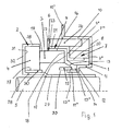
- Fig. 1 illustrated seal is designed as a mechanical seal, which has a cup-shaped housing 1, a sleeve-shaped holder 2, a slide ring 3 and a counter ring 4 in a known manner.
- the holder 2 is seated with a tubular inner shell 29 with a press fit on a shaft 5.
- the counter ring 4 is located with its facing away from the sliding ring 3 end face 31 at a radially outwardly projecting annular bottom 32 of the holder 2.
- the sliding ring 3 is rotatably mounted, while the counter-ring 4 rotates with the shaft 5.
- the sliding ring 3 is attached to a bellows formed as a secondary seal 6, which presses the slide ring 3 against the counter ring 4 under the force of a compression spring 7.
- the compression spring 7 rests with one end 7 'on a radial bottom 8 of the housing 1 and with its other end 7 "on a radially extending annular web 9' of a spring plate 9.
- the housing 1 has a cylindrical outer shell 10, the free edge 10 'is angled radially outward.
- the housing shell 10 adjoins the radially inwardly extending bottom 8, which adjoins a cylindrical inner shell 11. It goes about halfway along its axial length via a radially inwardly projecting shoulder surface 12 in a radially and axially further inside free inner shell portion 11 'over.
- the axis of the outer and inner shells 10 and 11 coincides with the axis of the shaft 5.
- the secondary seal 6 protrudes with a thickened inner edge 13 'of a cone part 12 in the outer shoulder 14 formed by the shoulder surface 12 and the shell portion 11'.
- a sleeve 15 is provided to compress the secondary seal 6 or its cone part 13 axially in the shoulder 14, which rests against the outside of the inner shell portion 11 'and an annular edge 13' of the cone part 13.
- the secondary seal 6 has in the illustration according to Fig. 1 approximately Z-shaped cross section with a cylindrical outer wall 16, which merges via a radially inwardly projecting annular portion 12 in the cone part 13.
- the sliding and the mating ring 3 and 4 are formed in a known manner and are therefore not described in detail.
- the secondary seal 6 lies with its annular portion 17 advantageously over its entire annular surface on the adjacent end face 18 of the slide ring 3. With its cylindrical outer wall 16, the secondary seal 6 bears against the outer jacket surface 19 of the sliding ring 3.
- the spring plate 9 has, similar to the secondary seal 6, Z-shaped cross-sectional shape.
- the radially inner part 20 of the spring plate 9 is cylindrical.
- the radially outer part 21 of the spring plate 9 is also cylindrical and surrounds the sliding ring over more than half its axial extent.
- the cylindrical part 21 of the spring plate 9 merges into a radially outwardly bent annular edge 22.
- a damping member 24 which in Fig. 12 is shown in more detail.
- the damping part 24 serves for vibration damping by generating micro friction. The micro-friction is generated between the damping part 24 and the inside of the outer shell 10 of the housing 1 and the outside of the cylinder part 21 of the spring plate 9.
- the inner jacket 29 of the holder 2 has an axially recessed cylinder portion 28 which connects to the ring bottom 32.
- the portion 28 has an axial extent which is slightly larger than the axial width of the counter-ring 4.
- the flange 32 is externally into a further cylinder portion 38 which extends coaxially to the portion 28 and has slightly smaller axial extent. This is equal to the axial width of the mating ring 4.
- At the cylindrical portion 28 of the holder 2 and the cylindrical inner surface 27 of the mating ring 4 is an annular sleeve 30 for sealing. Their axial extent is slightly smaller than that of the section 28 and slightly larger than that of the mating ring 4 or of the section 28 of the holder 2.
- the cuff 30 also serves to hold the mating ring 4 in the holder 2.
- the housing 1 protrudes with its cylindrical inner shell 11 with radial clearance in an annular space 33 which is formed between the sliding ring 3 and the inner shell 29 of the holder 2.
- the formation of the annular damping member 24 is based on Fig. 12 . 12a, 12b explained in more detail.
- the jacket 55 of the damping member 24 is profiled wavy. This will change the size of each other over the circumference Ribs 39 and recesses 25 formed.
- the ribs 39 and the recesses 25 are curved in radial section.
- the damping member 24 is located on the inner wall of the housing 1 and on the outside of the cylindrical part 21 of the spring plate 9 under prestress.
- Fig. 1 results, the damping member 24 protrudes axially from the housing 1 in the direction of the edge 22 of the secondary seal 6, which is located at an axial distance from the edge 10 'of the housing 1.
- the damping member 24 is located with its one end face on the ring edge 22.
- the other end of the damping member 24 has axial distance from the housing bottom. 8
- the damping member 24 has a larger number of ribs 39 and recesses 25.
- the damping part 24 is not closed. This results in an optimal elasticity of the damping part.
- the two ends 73, 74 of the damping member 24 may be spaced from each other. It is also possible that the ends 73, 74 overlap each other in the installation position. The two ends 73, 74 of the damping member 24 can move relative to each other in the circumferential direction of the damping member.
- the damping member 24 is formed by a shaped sheet metal part, which preferably consists of spring steel. Such a damping part can be manufactured easily and inexpensively.
- the damping member 24 is supported via the ribs 39 in the installed position radially on the housing 1 and the spring plate. By this radial support acting in the axial direction of the mechanical seal pressing or closing force acting on the slide ring 3, practically not affected. As a result, the tribological properties of the mechanical seal in the region of the sealing gap between the sliding ring 3 and the counter ring 4 by the installation of the damping member 24 remain unaffected. The damping member 24 effectively prevents the rotational or circumferential vibrations of the Sliding ring 3 during use, without affecting the sealing effect is adversely affected.
- the damping part 24 may be coated on at least one side, for example to obtain a corrosion protection, wear protection and the like. Such a coating can also be used in order to obtain a targeted micro friction between the damping part 24 and the housing 1 or the spring plate 9.
- the damping member 24 may also be completely sheathed.
- the damping member 24 may also be provided with corresponding surface structures to obtain desired micro-friction values.
- Such surface structures may be formed, for example, by roughening, laser-formed structures and the like.
- damping part 24 it is also possible, not the damping part 24, but to provide the corresponding counter surface on the housing 1 and the spring plate 9 with a corresponding coating and / or a corresponding surface structure.
- the holder 2 is advantageously formed by a steel part which is non-rotatably mounted on the shaft 5 to be sealed.
- the counter-ring 4 is used for dynamic sealing and rotates, since it is installed in the holder 2, together with the shaft 5.
- the sleeve 15 serves for the axial compression of the cone part 13 of the secondary seal 6, which forms the static seal of the mechanical seal.
- the compression spring 7 ensures that the slide ring 3 is pressed axially against the counter ring 4, so that the sealing gap between the slide ring 3 and the counter ring 4 is properly closed.
- the spring plate 9 serves as a press fit both for the sliding ring 3, which projects axially beyond the spring plate 9, as well as for the secondary seal. 6
- the damping member 24 is made of metal, preferably a molded spring plate. It requires only minimal installation space and is easy to manufacture.
- the damping member 24 is radially clamped between the jacket 21 of the spring plate 9 and the shell 10 of the housing 1, so that the ribs 39 of the damping member 24 rest under prestress on the spring plate 9 and the housing shell 10.
- the damping member 24 can absorb radial movements of the slide ring 3 by corresponding elastic deformation of the ribs 39 and the recesses 25.
- the described micro friction of the damping member 24 also leads to an excellent damping effect.
- the ribs 39 and the recesses 25 need not be provided over the entire axial width of the damping member 24.
- the ribs 39 and the recesses 25 of the profiled shell 55 extend only over half the axial width of the shell 55. They go over oblique intermediate portion 34 in a narrow cylinder portion 35 over.
- the depressions 25 are advantageously so deep that, in axial section according to Fig. 13 seen, the inner side 36 of the cylinder portion 35 also forms the lowest point of the recess 25 on the inside. Even with such a design is achieved with the damping member 24 excellent noise attenuation by micro friction.
- ribs 39 and recesses 25 may be provided in this embodiment, spaced apart tongues which are distributed over the circumference of the damping member 24.
- the cylinder portion 35 may consist of individual, circumferentially spaced behind one another tongues.
- the damping part 24 can be correspondingly Fig. 12 . 12a . 12b or Fig. 13 be educated.
- Fig. 2 shows a mechanical seal
- the sliding ring 3 is provided on its outer circumferential surface 19 with a recess 40 which is open to the end face 18.
- the secondary seal 6 engages. It has a cylindrical portion 41 which fills the depression and merges into a spring part 42 which is bent in a part-circular manner in axial section. It merges into a ring disk section 43 lying in a radial plane, with which the secondary seal 6 rests against the inside of the bottom 8 of the housing 1.
- the secondary seal 6 is formed so that the arcuate spring member is biased and thereby presses the sliding ring 3 against the counter ring 4. He sits with the interposition of the sleeve 30 on the cylinder portion 28 of the holder. 2
- the secondary seal 6 is pressed by the spring element 9 against the slide ring 3 and the housing bottom 8.
- the spring element 9 is shaped in axial section similar to the secondary seal 6.
- the spring element 9 is a molded part, which rests with a cylinder portion 45 on the secondary seal.
- To the cylinder portion 45 includes a part-circular curved in axial section spring portion 46 which rests against the outside of the spring member 42 of the secondary seal 6 and merges into an end portion 47. It extends radially and abuts against the annular disk section 43 of the secondary seal 6. With the end portion 47 of the annular disc portion 43 is pressed against the housing bottom 8.
- the damping member 24 is disposed between the spring member 9 and the housing 1.
- the damping member 24 rests with its ribs 39 on the cylinder portion 45 of the secondary seal 6 and on the outer jacket 10 of the housing 1 under elastic bias.
- the secondary seal 6 has no radially outwardly projecting annular edge, in contrast to the previous embodiment.
- the damping member 24 is in turn axially slightly above the housing 1 in the direction of the mating ring 4 and has clearance both from the end portion 47 of the spring element 9 and the annular disc portion 43 of the secondary seal 6.
- the damping member 24 may accordingly Fig. 12 . 12a . 12b or Fig. 13 be educated.
- a radial contact between the spring element 9 and the housing 1 is produced by the damping member 24.
- Fig. 3 shows a mechanical seal, which is similar to the mechanical seal after Fig. 1 , The difference is that the damping member 24 is not applied directly to the outer jacket 10 of the housing 1, but with the interposition of a retaining element 48. It has an L-shaped cross section with a radially inwardly extending flange 49, with which the retaining element 48 rests against the one end face of the damping part 24. The lying in a radial plane flange 49 connects radially on the outside of a cylinder jacket 50 which projects into the housing 1 and rests against the inner wall of the housing outer shell 10 over part of its length.
- the cylinder jacket 50 rests on the damping part 24 over its entire length, ie the ribs 39 of the damping part 24 bear on the inner wall of the cylinder jacket 50.
- the damping member 24 is secured axially in one direction. Due to the flange 49, the radially outwardly directed annular edge 22 of the spring plate 9, as in the embodiment according to FIG Fig. 1 provided, not required.
- the damping member 24 rests on the spring plate 9 in the manner described, which in turn is arranged on the secondary seal 6.
- this embodiment is the same as the embodiment according to FIG Fig. 1 ,
- Fig. 4 shows an embodiment which is formed substantially the same as the embodiment according to FIG Fig. 3 ,
- the retaining element 48 not only has the damping member 24 frontally cross-flange 49 at one end, but at the other end another, radially aligned flange 51. It lies against the radially outwardly directed flange 1 'of the housing 1 and is firmly connected to it.
- the two flanges 10 ' are advantageously the same length.
- the cylindrical inner sides of the outer shell 10 of the housing 1 and the retaining element 48 are advantageously in alignment with each other, so that no disturbing paragraph is formed at the transition between the flanges 10 ', 51.
- a continuous cylindrical support surface is formed for the damping part 24, which with its ribs 39 (FIG.
- Fig. 12 . Fig. 12a . 12b and 13 under radial prestress against the secondary seal 6, the spring plate 9 and the retaining element 48 and the housing shell 10.
- the radially inwardly directed flange 49 of the retaining element 48 is advantageously arranged so that its outer side lies with the end face of the cylinder portion 21 of the spring plate 9 in a common radial plane. But also the Front side of the outer wall 16 of the secondary seal 6 is advantageous in this radial plane.
- Fig. 5 shows a mechanical seal with the holder 2, which is the same design as in the embodiment according to Fig. 2 ,
- the counter ring 4 is covered only on its side facing away from the housing 1 end face of the ring bottom 32 of the holder 2, while its radially outer surface 44 is free.
- At the counter ring 4 of the slide ring 3 is located, as in the embodiment according to Fig. 2 has the recess 40 into which the cylindrical portion 41 of the secondary seal 6 engages.
- the mechanical seal has two spring plates 9a, 9b, the axial distance from each other and between which the compression spring 7 extends.
- the spring plate 9a rests with an inner cylindrical portion 53 on the cylinder portion 41 of the secondary seal 6.
- the free end of the cylinder portion 53 has a radially inwardly directed annular flange 54, with which the cylindrical portion 41 of the secondary seal 6 is axially loaded.
- At the other end of the cylinder portion 53 via a radially outwardly directed annular flange 56 in an outer cylinder portion 57 which extends into the housing 1 and the compression spring 7 covers over its greater part of its length radially outward.
- the annular flange 56 is equal to a shoulder surface 58, through which the recess 40 is axially limited in the sliding ring 3 in the direction of the counter ring 4. Under the force of the compression spring 7, the cylinder portion 41 of the secondary seal 6 is axially clamped between this shoulder surface 58 and the flange 54 of the spring plate 9a.
- the damping member 24 which according to the Fig. 12 . 12a . 12b or 13 is trained. In contrast to the previous exemplary embodiments, the damping part 24 does not project axially out of the housing 1.
- the spring plate 9b has an L-shaped cross section and is pressed by the compression spring 7 with its radially outwardly directed short flange 59 against the housing bottom 8.
- the flange 59 connects to a cylindrical jacket 56, with which the spring plate 9b rests on the cylinder portion 52 of the secondary seal 6 under radial prestressing.
- the cylinder portion 52 rests on the inner shell 11 of the housing 1.
- the inner shell portion 11 'of the housing 1 extends below the slip ring 3, the radial distance from the inner shell portion 11' has. Through it, the spring part of the secondary seal 6 is covered radially inward.
- the compression spring 7 is properly radially centered by the cylinder sections 53, 57 of the spring plate 9a.
- the damping part 24 is in turn arranged between the spring plate 9 a and the housing 1.
- the ribs 39 of the damping member 24 rest on the housing bottom 10 and on the cylinder portion 57 of the spring plate 9a under radial prestress.
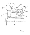
- Fig. 6 shows a modification of the embodiment according to Fig. 5 ,
- the spring plate 9a has a Z-shaped cross-section and rests with its radially outwardly directed annular flange 56 on the end face of the damping member 24.
- the damping member 24 protrudes axially from the housing 1.
- the spring plate 9a thus serves not only as a bearing for the compression spring 7, but also as an axial securing device for the damping element 24.
- the damping member 24 surrounds the compression spring 7 almost over the entire axial length, so that it is properly radially centered. In this embodiment, there is a radial contact between the damping part 24 and the compression spring 7 and the outer shell 10 of the housing first
- this embodiment is the same design as the mechanical seal after Fig. 5 ,
- Fig. 7 is the damping member 24 on a cylinder portion 61 of the spring plate 9a.
- the cylinder portion 61 extends in the direction of the counter-ring 4 from the annular flange 56.
- the cylinder portion 61 engages over the counter ring 4 with a small radial distance.
- the compression spring 7 extends between the shoulder surface 56 of the spring plate 9a and the flange 59 of the spring plate 9b.
- the damping member 24 extends axially from the housing 1. Within the housing 1, the damping member 24 abuts against the inner wall of the housing outer jacket under radial bias. Outside the housing 1, it is supported by the cylinder portion 61 of the spring plate 9a. It is also loaded by the damping member 24 radially inwardly so that it radially presses the cylinder portion 41 of the secondary seal 6 against the seal ring 3.
- the damping part 24 extends up to the level of the sliding ring 3 facing end face of the mating ring 4. As in the previous embodiments, the damping member 24 has axial distance from the housing bottom. 8
- the damping member 24 between the spring plate 9a and an inner wall 62 of a receiving space 63 of a pump housing 64 is arranged.
- the spring plate 9a has the radially outwardly directed flange 56, which is substantially wider in contrast to the previous embodiment and merges at the radially outer end into a cylinder section 65 against which the damping part 24 abuts.
- the Cylinder portion 65 extends into the region above the mating ring 4 and is provided at the free end with a radially outwardly directed flange 66 which rests against the end face of the damping member 24 and secures it axially.
- the flange 56 is at an axial distance to the radially outwardly directed housing flange 10 ', with which the housing 1 rests against the bottom 67 of the receiving space 63.
- the damping member 24 is axially spaced from the flange 10 '.
- the flange 56 projects radially outwardly so far that it lies in the height of the housing flange 10 '.
- the compression spring 7 extends between the flange 56 and the radially outwardly directed flange 59 of the spring plate 9b.
- the compression spring 7 rests on the cylinder sections 53, 60 of the two spring plates 9a, 9b.
- this embodiment is the same as the previous embodiment.
- the mechanical seal after Fig. 9 has the damping member 68, which has in contrast to the damping member 24 as a spring portion no ribs and depressions, but cylindrical spring portions.
- the embodiment is the same as the embodiment according to except for the design of the damping member Fig. 2 ,
- the damping part 68 is designed as a ring cup, which has a radially outer cylinder jacket 69 and a radially inner cylinder jacket 70, which merge into one another through a radial bottom 71.
- the two cylinder jackets 69, 70 are coaxial with each other and to be sealed shaft 5.
- the outer cylinder jacket 69 is axially longer than the inner cylinder jacket 70.
- the outer cylinder jacket 69 projects into the housing 1 and is applied to the inner wall of the housing shell 10 under radial prestress.
- the shorter cylinder jacket 70 rests on the cylindrical portion 41 of the secondary seal 6 and loads it in the radial direction.
- the cylinder jacket 70 has a small axial distance from the cylinder portion 45 of the spring plate 9.
- the lying in a radial plane Floor 71 of the damping member 68 is equal to the shoulder surface 58 of the sliding ring. 3
- the cylinder jacket 69 is radially resilient so that it can absorb corresponding radial movements of the seal ring 3 by elastic deformation. The noise is thereby avoided. As with the damping member 24, the intended micro-friction contributes to optimal damping.
- the mechanical seal after Fig. 10 essentially corresponds to the embodiment according to Fig. 9 ,
- the damping member 68 has the cylindrical outer jacket 69, which rests in the manner described under radial bias on the inside of the shell 10 of the housing 1.
- the radially inner cylinder jacket 70 does not extend in the same direction as the outer cylinder jacket 69, but in the direction of the mating ring 4.
- the inner cylinder jacket 70 is located on the outer circumferential surface 19 of the seal ring 3 in the area outside the recess 40th on.
- the cylinder jacket 69 is sufficiently resilient due to its axial length, so that it can yield radially correspondingly.
- the mechanical seal is the same way as the embodiment according to the rest Fig. 9 ,
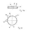
- Fig. 11 shows a damping member 68, the bottom 71 is formed part-circular curved in axial section.
- the radially inner cylinder jacket 70 rests on the cylinder portion 45 of the spring plate 9 under radial bias.
- the outer cylinder jacket 69 according to the Fig. 12 . 12a . 12b and 13 be profiled wavy over its circumference, so that the cylinder jacket rests only with the rib-like elevations on the housing shell 10.
- the mechanical seal according to the invention Fig. 14 In its construction substantially corresponds to the embodiment according to Fig. 1 , The difference lies in the design and arrangement of the damping part 24. It is supported axially on the cylindrical part 21 of the spring plate 9, which sits on the secondary seal 6 and on which the compression spring 7 engages. The damping member 24 is also supported on the radially outwardly projecting edge 10 'of the housing 1.
- the damping member 24 has the in the FIGS. 15 and 16 illustrated training. It is designed as a closed ring and has a ring member 75 which is formed as a flat annular disc. On the inside 76 of the ring member 75 distributed over the circumference spring tongues 77 are provided, which are advantageously the same design and advantageously have the same distance from each other.
- the spring tongues project obliquely inwards and are elastically deformed in the installation position of the damping part 24.
- Fig. 14 are the spring tongues 77 under elastic deformation on the cylindrical part 21 of the spring plate 9 at.
- the damping member 24 is located on the radially outwardly directed edge 10 'of the housing 1 at.
- the spring tongues 77 project slightly in the direction of the bottom 8 of the housing 1 via the annular web 9 'of the spring plate 9.
- the spring tongues 7 also have a radial distance from the inner wall of the outer shell 10 of the housing first
- the damping member 24 is again installed so that the spring tongues 77 generate the micro-friction for noise damping in the circumferential direction.
- This circumferential direction is, as already with the damping parts 24 according to the Fig. 12 . 12a . 12b and 13 , the main direction for the generation of micro friction, while the axial direction of the mechanical seal for the vibration damping plays no role.
- the mechanical seal according to the invention Fig. 17 is the same design as the mechanical seal after Fig. 14 , Only the damping member 24 has a different design and installation position.
- the spring tongues 77 of the damping member 24 are provided on the outside of the disc-shaped ring member 75.
- the spring tongues 77 are directed obliquely outwards. They lie in the installed position under elastic deformation on the inside of the outer shell 10 of the housing 1 ( Fig. 17 ).
- the spring tongues 77 extend from the ring part 75 slightly beyond the radially outwardly directed free edge 10 'of the housing 1.
- the spring tongues 77 are at a radial distance from the spring plate 9.
- the ring member 75 of the damping member 24 abuts the radial annular web 9 'of the spring plate 9 under the force of the compression spring 7.
- the ring member 75 may extend to the radially inner cylinder portion 20 of the spring plate 9.
- the elastic spring tongues 77 are under elastic bias on the housing 1, while lying in a radial plane ring member 75 rests against the radial annular web 9 'of the spring plate 9.
- Fig. 20 shows a mechanical seal, which is formed substantially the same as the mechanical seal according to the Fig. 14 or 17 , Only the damping part 24 has a different design.
- the damping member 24 has two disc-shaped ring members 78, 79 which are each in a radial plane of the mechanical seal and pass through a serving as a spring part cone member 80 into each other.
- the radially outer ring member 78 abuts the free edge 10 'of the housing 1.
- the radially inner ring member 79 abuts the radial annular web 9 'of the spring plate 9.
- the ring member 79 is pressed by the compression spring 7 axially against the radial annular web 9 'of the spring plate 9.
- the micro friction occurs between the radially extending ring members 78, 79 of the damping member 24 and the radial Edge 10 'of the housing 1 and the radial annular web 9' of the spring plate.
- the damping part 24 has cylindrical ring parts 78 ', 79'.
- the damping part 24 is arranged so that the annular part 78 'rests on the outside of the cylinder part 21 of the spring plate 9 and the ring part 79' on the inside of the outer shell 10 of the housing 1.
- the cylindrical ring members 78 'and 79' are interconnected by the cone member 80.
- the mechanical seal is the same design as the mechanical seal according to Fig. 20 ,
- the ring parts 69, 70; 77, 78, 79; 78 ', 79' can be segmented.
- the damping member 24 is formed integrally with the spring plate 9.
- the mechanical seal has the same structure as the mechanical seal Fig. 1 ,
- the radially outwardly directed annular edge of the spring plate 9 forms the damping part 24 which is surrounded by the retaining element 48. It is according to the embodiment according to Fig. 4 formed and is attached with its flange 51 at the free edge 10 'of the housing 1.
- a spring member 81 is supported, which extends between the flange 49 and the damping member 24 and rests under axial bias on these two parts.
- the spring member 81 may be, for example, a corrugated spring.
Description
- Die Erfindung betrifft eine Gleitringdichtung nach dem Oberbegriff des Anspruches 1.
- Bei Gleitringdichtungen tritt das Problem auf, dass sie unter bestimmten Einsatzbedingungen Geräusche erzeugen. Es gibt derzeit keine wirkungsvollen Maßnahmen, um die Gleitringdichtung ausreichend zu dämpfen und die Geräusche zu vermeiden.
- Gleitringdichtungen mit Dämpfungsteilen sind bekannt aus z.B.
FR 2 787 851 US 6,311,983 undDE 197 39 398 . - Der Erfindung liegt die Aufgabe zugrunde, die gattungsgemäße Gleitringdichtung so auszubilden, dass sie kostengünstig gefertigt werden kann und eine wirkungsvolle Geräuschdämpfung gewährleistet.
- Diese Aufgabe wird bei der gattungsgemäßen Gleitringsdichtung erfindungsgemäß mit den kennzeichnenden Merkmalen des Anspruches 1 gelöst.
- Das Dämpfungsteil weist ein geformtes Blechteil auf, das sich einfach und kostengünstig herstellen lässt. Aufgrund seiner Formstabilität kann es einfach in die Gleitringdichtung eingebaut werden. Der Blechteil gewährleistet eine lange Einsatzdauer des Dämpfungsteiles. Mit dem Federteil ist das Dämpfungsteil unter Vorspannung abgestützt. Aufgrund der metallischen Ausbildung des Dämpfungsteiles kann eine gezielte Vorspannkraft eingestellt werden, um eine an den Einsatzfall der Gleitringdichtung optimal angepasste Dämpfungswirkung zu erzielen. Zwischen dem Dämpfungsteil und dem Abstützbereich entsteht eine Mikroreibung, die zur Dämpfungswirkung führt. Das Dämpfungsteil unterdrückt auch bei extremsten Betriebsbedingungen Geräusche wirkungsvoll. Es kann kostengünstig gefertigt und problemlos eingebaut werden und gewährleistet gleichzeitig eine lange Betriebsdauer. Die Gleitringdichtung wird vorteilhaft in der Kraftfahrzeugtechnik eingesetzt.
- Bei einer Ausgestaltung hat das Dämpfungsteil einen äußeren Mantel, der an einer Wandung des Einbauraumes der Gleitringdichtung unter radialer Vorspannung abgestützt ist.
- Vorteilhaft ist es, wenn der Federteil über seinen Umfang mit einer Profilierung, vorzugsweise einer wellenförmigen Profilierung, versehen ist. Sie gewährleistet zum einen eine optimale Dämpfung, zum anderen wird dadurch eine hohe Stabilität des Dämpfungsteiles erzielt.
- Die erfindungsgemäße Gleitringdichtung wird bevorzugt bei Wasserpumpen zur Geräuschdämpfung eingesetzt. Das Dämpfungsteil, insbesondere sein Federteil, ist so ausgebildet, dass es eine Mikroreibung erzeugt, die zu einer optimalen Geräuschdämpfung führt.
- Weitere Merkmale der Erfindung ergeben sich aus den weiteren Ansprüchen, der Beschreibung und den Zeichnungen.
- Die Erfindung wird nachstehend anhand mehrerer in den Zeichnungen dargestellter Ausführungsformen näher erläutert. Es zeigen
- Fig. 1 bis Fig. 11
- jeweils eine Hälfte einer Ausführungsform einer Gleitringdichtung im Axialschnitt,
- Fig. 12
- eine Hälfte einer ersten Ausführungsform eines ringförmigen Dämpfungsteiles der Gleitringdichtung im Axialschnitt,
- Fig. 12a
- das Dämpfungsteil gemäß
Fig. 12 in Seitenansicht, - Fig. 12b
- das Dämpfungsteil gemäß
Fig. 12 in Draufsicht, - Fig. 13
- in einer Darstellung entsprechend
Fig. 12 eine zweite Ausfüh- rungsform eines ringförmigen Dämpfungsteils, - Fig. 14
- jeweils eine Hälfte einer Ausführungsform einer erfindungsgemäßen Gleitringdichtung im Axialschnitt,
- Fig. 15
- in Seitenansicht ein ringförmiges Dämpfungsteil der erfindungsgemäßen Gleitringdichtung gemäß
Fig. 14 , - Fig. 16
- das Dämpfungsteil gemäß
Fig. 15 in Draufsicht, - Fig. 17
- eine Hälfte einer weiteren Ausführungsform einer erfindungsgemäßen Gleitringdichtung im Axialschnitt,
- Fig. 18
- eine weitere Ausführungsform eines ringförmigen Dämpfungsteiles der Gleitringdichtung gemäß
Fig. 17 , - Fig. 19
- eine Draufsicht auf das Dämpfungsteil gemäß
Fig. 18 , - Fig. 20 und Fig. 22
- jeweils eine Hälfte einer weiteren Ausführungsform einer Gleitringdichtung im Axialschnitt.
- Die in
Fig. 1 dargestellte Dichtung ist als Gleitringdichtung ausgebildet, die in bekannter Weise ein napfförmiges Gehäuse 1, eine buchsenförmige Halterung 2, einen Gleitring 3 und einen Gegenring 4 aufweist. Die Halterung 2 sitzt mit einem rohrförmigen Innenmantel 29 mit Presssitz auf einer Welle 5. Der Gegenring 4 liegt mit seiner vom Gleitring 3 abgewandten Stirnseite 31 an einem radial nach außen ragenden Ringboden 32 der Halterung 2 an. Der Gleitring 3 ist drehfest gelagert, während der Gegenring 4 mit der Welle 5 dreht. Der Gleitring 3 ist an einer als Balg ausgebildeten Sekundärdichtung 6 befestigt, die unter der Kraft einer Druckfeder 7 den Gleitring 3 gegen den Gegenring 4 drückt. Die Druckfeder 7 liegt mit einem Ende 7' an einem radialen Boden 8 des Gehäuses 1 und mit ihrem anderen Ende 7" an einem radial verlaufenden Ringsteg 9' eines Federtellers 9 an. - Das Gehäuse 1 hat einen zylindrischen Außenmantel 10, dessen freier Rand 10' radial nach außen abgewinkelt ist. Der Gehäusemantel 10 schließt an den radial nach innen verlaufenden Boden 8 an, der an einen zylindrischen Innenmantel 11 anschließt. Er geht etwa in halber axialer Länge über eine radial nach innen ragende Schulterfläche 12 in einen radial und axial weiter innen liegenden freien Innenmantelabschnitt 11' über. Die Achse des Außen- und Innenmantels 10 und 11 fällt mit der Achse der Welle 5 zusammen.
- Die Sekundärdichtung 6 ragt mit einem verdickten Innenrand 13' eines Konusteiles 12 in die durch die Schulterfläche 12 und den Mantelabschnitt 11' gebildete Außenschulter 14. Um die Sekundärdichtung 6 bzw. seinen Konusteil 13 in der Schulter 14 axial zu verpressen, ist eine Hülse 15 vorgesehen, die an der Außenseite des Innenmantelabschnittes 11' und einem Ringrand 13' des Konusteiles 13 anliegt. Die Sekundärdichtung 6 hat in der Darstellung gemäß
Fig. 1 etwa Z-förmigen Querschnitt mit einer zylindrischen Außenwand 16, die über einen radial nach innen ragenden Ringabschnitt 12 in den Konusteil 13 übergeht. - Der Gleit- und der Gegenring 3 und 4 sind in bekannter Weise ausgebildet und werden daher nicht näher beschrieben.
- Die Sekundärdichtung 6 liegt mit ihrem Ringabschnitt 17 vorteilhaft über ihre ganze Ringfläche an der benachbarten Stirnfläche 18 des Gleitringes 3 an. Mit ihrer zylindrischen Außenwand 16 liegt die Sekundärdichtung 6 an der äußeren Mantelfläche 19 des Gleitringes 3 an. Der Federteller 9 hat, ähnlich wie die Sekundärdichtung 6, Z-förmige Querschnittsform. Im Unterschied zur Sekundärdichtung 6 ist der radial innere Teil 20 des Federtellers 9 zylindrisch ausgebildet. Der radial äußere Teil 21 des Federtellers 9 ist ebenfalls zylindrisch ausgebildet und umgibt den Gleitring über mehr als dessen halbe axiale Erstreckung. Der zylindrische Teil 21 des Federtellers 9 geht in einen radial nach außen gebogenen Ringrand 22 über. An einer durch den Rand 22 und den zylindrischen Teil 21 begrenzten Außenschulter 23 des Federtellers 9 liegt ein Dämpfungsteil 24 an, das in
Fig. 12 näher dargestellt ist. Das Dämpfungsteil 24 dient zur Schwingungsdämpfung durch Erzeugung von Mikroreibung. Die Mikroreibung wird zwischen dem Dämpfungsteil 24 und der Innenseite des Außenmantels 10 des Gehäuses 1 sowie der Außenseite des Zylinderteils 21 des Federtellers 9 erzeugt. - Der Innenmantel 29 der Halterung 2 hat einen axial zurückversetzten Zylinderabschnitt 28, der an den Ringboden 32 anschließt. Der Abschnitt 28 hat eine axiale Erstreckung, die geringfügig größer ist als die axiale Breite des Gegenringes 4. Der Flansch 32 geht außen in einen weiteren Zylinderabschnitt 38 über, der koaxial zum Abschnitt 28 verläuft und geringfügig kleinere axiale Erstreckung hat. Diese ist gleich der axialen Breite des Gegenringes 4. Am zylindrischen Abschnitt 28 der Halterung 2 und der zylindrischen Innenfläche 27 des Gegenringes 4 liegt eine ringförmige Manschette 30 zur Abdichtung an. Ihre axiale Erstreckung ist geringfügig kleiner als die des Abschnittes 28 und geringfügig größer als die des Gegenringes 4 bzw. des Abschnittes 28 der Halterung 2. Die Manschette 30 dient auch zur Halterung des Gegenringes 4 in der Halterung 2.
- Das Gehäuse 1 ragt mit seinem zylindrischen Innenmantel 11 mit radialem Spiel in einen Ringraum 33, der zwischen dem Gleitring 3 und dem Innenmantel 29 der Halterung 2 gebildet ist.
- Die Ausbildung des ringförmigen Dämpfungsteiles 24 wird anhand von
Fig. 12 ,12a, 12b näher erläutert. Der Mantel 55 des Dämpfungsteiles 24 ist wellenförmig profiliert. Dadurch werden über den Umfang einander abwechseinde Rippen 39 und Vertiefungen 25 gebildet. Vorteilhaft sind die Rippen 39 und die Vertiefungen 25 im Radialschnitt gekrümmt ausgebildet. Mit den Rippen 39 liegt das Dämpfungsteil 24 an der Innenwandung des Gehäuses 1 sowie an der Außenseite des zylindrischen Teiles 21 des Federtellers 9 unter Vorspannung an. Wie sich ausFig. 1 ergibt, ragt das Dämpfungsteil 24 axial aus dem Gehäuse 1 in Richtung auf den Rand 22 der Sekundärdichtung 6, die mit axialem Abstand vom Rand 10' des Gehäuses 1 liegt. Das Dämpfungsteil 24 liegt mit seiner einen Stirnseite am Ringrand 22 an. Die andere Stirnseite des Dämpfungsteiles 24 hat axialen Abstand vom Gehäuseboden 8. - Wie die
Fig. 12a und 12b zeigen, weist das Dämpfungsteil 24 eine größere Zahl von Rippen 39 und Vertiefungen 25 auf. Das Dämpfungsteil 24 ist nicht geschlossen. Dadurch ergibt sich eine optimale Elastizität des Dämpfungsteils. In der Einbaulage können die beiden Enden 73, 74 des Dämpfungsteils 24 Abstand voneinander haben. Es ist auch möglich, dass die Enden 73, 74 in der Einbaulage einander überlappen. Die beiden Enden 73, 74 des Dämpfungsteils 24 können sich relativ zueinander in Umfangsrichtung des Dämpfungsteils bewegen. - Das Dämpfungsteil 24 wird durch ein geformtes Blechteil gebildet, das vorzugsweise aus Federstahl besteht. Ein solches Dämpfungsteil lässt sich einfach und kostengünstig fertigen.
- Das Dämpfungsteil 24 wird über die Rippen 39 in der Einbaulage radial am Gehäuse 1 sowie am Federteller abgestützt. Durch diese Radialabstützung wird die in Axialrichtung der Gleitringdichtung wirkende Anpress- bzw. Schließkraft, die auf den Gleitring 3 wirkt, praktisch nicht beeinträchtigt. Dadurch bleiben die tribologischen Eigenschaften der Gleitringdichtung im Bereich des Dichtspaltes zwischen dem Gleitring 3 und dem Gegenring 4 durch den Einbau des Dämpfungsteiles 24 unbeeinflusst. Das Dämpfungsteil 24 verhindert wirkungsvoll die Dreh- bzw. Umfangsschwingungen des Gleitringes 3 während des Einsatzes, ohne dass hierdurch die Dichtwirkung nachteilig beeinflusst wird.
- Das Dämpfungsteil 24 kann zumindest an einer Seite beschichtet sein, beispielsweise um einen Korrosionsschutz, einen Verschleißschutz und dergleichen zu erhalten. Auch kann eine solche Beschichtung verwendet werden, um eine gezielte Mikroreibung zwischen dem Dämpfungsteil 24 und dem Gehäuse 1 bzw. dem Federteller 9 zu erhalten.
- Das Dämpfungsteil 24 kann auch vollständig ummantelt sein.
- Es ist weiter möglich, an der Innen- und an der Außenseite des Dämpfungsteiles 24 unterschiedliche Beschichtungen vorzusehen. Dadurch ist es möglich, an beiden Seiten des Dämpfungsteils 24 unterschiedliche Mikroreibungswerte zu erhalten. Dadurch ist eine sehr einfache und dennoch wirkungsvolle Anpassung an unterschiedliche Einbauverhältnisse möglich.
- Das Dämpfungsteil 24 kann auch mit entsprechenden Oberflächenstrukturen versehen sein, um gewünschte Mikroreibungswerte zu erhalten. Solche Oberflächenstrukturen können beispielsweise durch Aufrauen, durch Laser gebildete Strukturen und dergleichen gebildet sein.
- Es ist ferner möglich, nicht das Dämpfungsteil 24, sondern die entsprechende Gegenfläche am Gehäuse 1 bzw. am Federteller 9 mit einer entsprechenden Beschichtung und/oder einer entsprechenden Oberflächenstruktur zu versehen.
- Mit dem Dämpfungsteil 24 wird eine Geräuschbildung beim Einsatz der Gleitringdichtung zuverlässig vermieden. Mit dem Dämpfungsteil 24 wird über die Rippen 39 ein Radialkontakt zwischen dem Federteller 9 und dem Gehäuse 1 hergestellt.
- Die Halterung 2 wird vorteilhaft durch ein Stahlteil gebildet, das drehfest auf der abzudichtenden Welle 5 sitzt. Der Gegenring 4 dient zur dynamischen Abdichtung und dreht, da er in die Halterung 2 eingebaut ist, zusammen mit der Welle 5. Die Hülse 15 dient zur axialen Verpressung des Konusteiles 13 der Sekundärdichtung 6, welche die statische Abdichtung der Gleitringdichtung bildet. Mit dem Gehäuse 1 wird die Gleitringdichtung in den Aufnahmeraum eines (nicht dargestellten) Bauteiles, beispielsweise eines Pumpengehäuses, eingepresst. Der Außenmantel 10 des Gehäuses 1 liegt dann unter Presssitz an der Wandung des Aufnahmeraumes an. Der radial nach außen gerichtete Flansch 10' des Außenmantels 10 kann beim Einbau der Gleitringdichtung als Anschlag dienen, wenn das Gehäuse 1 in den Aufnahmeraum eingepresst wird. Die Druckfeder 7 sorgt dafür, dass der Gleitring 3 axial gegen den Gegenring 4 gedrückt wird, so dass der Dichtspalt zwischen dem Gleitring 3 und dem Gegenring 4 einwandfrei geschlossen wird. Der Federteller 9 dient als Presssitz sowohl für den Gleitring 3, der axial über den Federteller 9 vorsteht, als auch für die Sekundärdichtung 6.
- Das Dämpfungsteil 24 besteht aus Metall, vorzugsweise einem geformten Federblech. Es benötigt nur geringen Einbauraum und lässt sich einfach herstellen. Das Dämpfungsteil 24 ist zwischen dem Mantel 21 des Federtellers 9 und dem Mantels 10 des Gehäuses 1 radial eingespannt, so dass die Rippen 39 des Dämpfungsteiles 24 unter Vorspannung am Federteller 9 sowie am Gehäusemantel 10 anliegen. Das Dämpfungsteil 24 kann radiale Bewegungen des Gleitringes 3 durch entsprechende elastische Verformung der Rippen 39 bzw. der Vertiefungen 25 auffangen. Die beschriebene Mikroreibung des Dämpfungsteiles 24 führt darüber hinaus zu einer hervorragenden Dämpfungswirkung.
- Wie
Fig. 13 beispielhaft zeigt, müssen die Rippen 39 und die Vertiefungen 25 nicht über die gesamte axiale Breite des Dämpfungsteiles 24 vorgesehen sein. Die Rippen 39 und die Vertiefungen 25 des profilierten Mantels 55 erstrecken sich nur über die halbe axiale Breite des Mantels 55. Sie gehen über schräg verlaufende Zwischenabschnitt 34 in einen schmalen Zylinderabschnitt 35 über. Die Vertiefungen 25 sind vorteilhaft so tief, dass, im Axialschnitt gemäßFig. 13 gesehen, die Innenseite 36 des Zylinderabschnittes 35 auch die tiefste Stelle der Vertiefung 25 an deren Innenseite bildet. Auch mit einer solchen Ausbildung wird mit dem Dämpfungsteil 24 eine hervorragende Geräuschdämpfung durch Mikroreibung erreicht. - Anstelle der Rippen 39 und Vertiefungen 25 können bei dieser Ausführungsform auch mit Abstand voneinander liegende Zungen vorgesehen sein, die über den Umfang des Dämpfungsteils 24 verteilt angeordnet sind. Auch der Zylinderabschnitt 35 kann aus einzelnen, in Umfangsrichtung mit Abstand hintereinander liegenden Zungen bestehen.
- Bei der Gleitringdichtung nach
Fig. 1 kann das Dämpfungsteil 24 entsprechendFig. 12 ,12a ,12b oderFig. 13 ausgebildet sein. -
Fig. 2 zeigt eine Gleitringdichtung, deren Gleitring 3 an seiner äußeren Mantelfläche 19 mit einer Vertiefung 40 versehen ist, die zur Stirnseite 18 offen ist. In diese ringförmige Vertiefung 40 greift die Sekundärdichtung 6 ein. Sie hat einen zylindrischen Abschnitt 41, der die Vertiefung ausfüllt und in einen im Axialschnitt teilkreisförmig gebogenen Federteil 42 übergeht. Er geht in einen in einer Radialebene liegenden Ringscheibenabschnitt 43 über, mit dem die Sekundärdichtung 6 an der Innenseite des Bodens 8 des Gehäuses 1 anliegt. Die Sekundärdichtung 6 ist so ausgebildet, dass der bogenförmige Federteil vorgespannt ist und dadurch den Gleitring 3 gegen den Gegenring 4 drückt. Er sitzt unter Zwischenlage der Manschette 30 auf dem Zylinderabschnitt 28 der Halterung 2. - Im Unterschied zur vorigen Ausführungsform schließt an den Ringboden 32 der Halterung 2 kein Zylinderabschnitt an. Dadurch wird die äußere Mantelfläche 44 des Gegenringes 4 nicht abgedeckt. Der Ringboden 32 ist in Radialrichtung nur so lang, dass seine freie Stirnseite fluchtend zur Mantelfläche 44 des Gegenringes 4 liegt. Dadurch wird kein störender Absatz gebildet, in dem sich während des Betriebes der Gleitringdichtung Schmutzteilchen und dgl. absetzen können.
- Die Sekundärdichtung 6 wird durch das Federelement 9 gegen den Gleitring 3 sowie den Gehäuseboden 8 gedrückt. Das Federelement 9 ist im Axialschnitt ähnlich geformt wie die Sekundärdichtung 6. Das Federelement 9 ist ein Formteil, das mit einem Zylinderabschnitt 45 auf der Sekundärdichtung aufliegt. An den Zylinderabschnitt 45 schließt ein im Axialschnitt teilkreisförmig gekrümmter Federabschnitt 46 an, der an der Außenseite des Federteiles 42 der Sekundärdichtung 6 anliegt und in einen Endabschnitt 47 übergeht. Er erstreckt sich radial und liegt am Ringscheibenabschnitt 43 der Sekundärdichtung 6 an. Mit dem Endabschnitt 47 wird der Ringscheibenabschnitt 43 gegen den Gehäuseboden 8 gedrückt.
- Wie bei der vorigen Ausführungsform ist das Dämpfungsteil 24 zwischen dem Federelement 9 und dem Gehäuse 1 angeordnet. Das Dämpfungsteil 24 liegt mit seinen Rippen 39 am Zylinderabschnitt 45 der Sekundärdichtung 6 sowie am Außenmantel 10 des Gehäuses 1 unter elastischer Vorspannung an. Die Sekundärdichtung 6 hat im Unterschied zur vorigen Ausführungsform keinen radial nach außen ragenden Ringrand. Das Dämpfungsteil 24 steht wiederum axial geringfügig über das Gehäuse 1 in Richtung auf den Gegenring 4 vor und hat Abstand sowohl vom Endabschnitt 47 des Federelementes 9 als auch vom Ringscheibenabschnitt 43 der Sekundärdichtung 6. Das Dämpfungsteil 24 kann entsprechend
Fig. 12 ,12a ,12b oderFig. 13 ausgebildet sein. Wie bei der vorigen Ausführungsform wird durch das Dämpfungsteil 24 ein radialer Kontakt zwischen dem Federelement 9 und dem Gehäuse 1 hergestellt. -
Fig. 3 zeigt eine Gleitringdichtung, die ähnlich aufgebaut ist wie die Gleitringdichtung nachFig. 1 . Der Unterschied besteht darin, dass das Dämpfungsteil 24 nicht unmittelbar am Außenmantel 10 des Gehäuses 1 anliegt, sondern unter Zwischenlage eines Rückhalteelementes 48. Es hat L-förmigen Querschnitt mit einem radial nach innen verlaufenden Flansch 49, mit dem das Rückhaltelement 48 an der einen Stirnseite des Dämpfungsteiles 24 anliegt. Der in einer Radialebene liegende Flansch 49 schließt radial außen an einen Zylindermantel 50 an, der in das Gehäuse 1 ragt und über einen Teil seiner Länge an der Innenwand des Gehäuseaußenmantels 10 anliegt. Der Zylindermantel 50 liegt über seine gesamte Länge auf dem Dämpfungsteil 24 auf, d.h. die Rippen 39 des Dämpfungsteiles 24 liegen an der Innenwand des Zylindermantels 50 an. Durch den Flansch 49 wird das Dämpfungsteil 24 axial in einer Richtung gesichert. Aufgrund des Flansches 49 ist der radial nach außen gerichtete Ringrand 22 des Federtellers 9, wie bei der Ausführungsform gemäßFig. 1 vorgesehen, nicht erforderlich. Das Dämpfungsteil 24 liegt auf dem Federteller 9 in der beschriebenen Weise auf, der seinerseits auf der Sekundärdichtung 6 angeordnet ist. Im Übrigen ist diese Ausführungsform gleich ausgebildet wie das Ausführungsbeispiel gemäßFig. 1 . -
Fig. 4 zeigt eine Ausführungsform, die im Wesentlichen gleich ausgebildet ist wie das Ausführungsbeispiel gemäßFig. 3 . Das Rückhalteelement 48 weist nicht nur den das Dämpfungsteil 24 stirnseitig übergreifenden Flansch 49 an einem Ende, sondern am anderen Ende einen weiteren, radial ausgerichteten Flansch 51 auf. Er liegt am radial nach außen gerichteten Flansch 1' des Gehäuses 1 an und ist fest mit ihm verbunden. Die beiden Flansche 10' sind vorteilhaft gleich lang. Die zylindrischen Innenseiten des Außenmantels 10 des Gehäuses 1 und des Rückhalteelementes 48 liegen vorteilhaft fluchtend aneinander, so dass am Übergang zwischen den Flanschen 10', 51 kein störender Absatz gebildet wird. Dadurch wird auch eine durchgehende zylindrische Abstützfläche für das Dämpfungsteil 24 gebildet, das mit seinen Rippen 39 (Fig. 12 ,Fig. 12a ,12b und13 ) unter radialer Vorspannung an der der Sekundärdichtung 6, am Federteller 9 sowie am Rückhalteelement 48 und am Gehäusemantel 10 anliegt. Der radial nach innen gerichtete Flansch 49 des Rückhalteelementes 48 ist vorteilhaft so angeordnet, dass seine Außenseite mit der Stirnseite des Zylinderabschnittes 21 des Federtellers 9 in einer gemeinsamen Radialebene liegt. Aber auch die Stirnseite der Außenwand 16 der Sekundärdichtung 6 liegt vorteilhaft in dieser Radialebene. - Im Übrigen ist die Gleitringdichtung nach
Fig. 4 gleich ausgebildet wie die Ausführungsform nachFig.1 . -
Fig. 5 zeigt eine Gleitringdichtung mit der Halterung 2, die gleich ausgebildet ist wie bei der Ausführungsform gemäßFig. 2 . Der Gegenring 4 wird lediglich an seiner vom Gehäuse 1 abgewandten Stirnseite vom Ringboden 32 der Halterung 2 bedeckt, während seine radial äußere Mantelfläche 44 frei ist. Am Gegenring 4 liegt der Gleitring 3 an, der wie bei der Ausführungsform nachFig. 2 die Vertiefung 40 aufweist, in die der zylindrische Abschnitt 41 der Sekundärdichtung 6 eingreift. An den zylindrischen Abschnitt 41 schließt der Federteil 42 an, der im Unterschied zum Ausführungsbeispiel gemäßFig. 2 in einen weiteren zylindrischen Abschnitt 52 übergeht, der vorteilhaft gleich ausgebildet ist wie der Zylinderabschnitt 41. - Die Gleitringdichtung hat zwei Federteller 9a, 9b, die axialen Abstand voneinander haben und zwischen denen sich die Druckfeder 7 erstreckt. Der Federteller 9a liegt mit einem inneren zylindrischen Abschnitt 53 auf dem Zylinderabschnitt 41 der Sekundärdichtung 6 auf. Das freie Ende des Zylinderabschnittes 53 hat einen radial nach innen gerichteten Ringflansch 54, mit dem der zylindrische Abschnitt 41 der Sekundärdichtung 6 axial belastet wird. Am anderen Ende geht der Zylinderabschnitt 53 über einen radial nach außen gerichteten Ringflansch 56 in einen äußeren Zylinderabschnitt 57 über, der sich in das Gehäuse 1 erstreckt und die Druckfeder 7 über ihren größten Teil ihrer Länge radial nach außen abdeckt. Der Ringflansch 56 liegt in Höhe einer Schulterfläche 58, durch welche die Vertiefung 40 im Gleitring 3 in Richtung auf den Gegenring 4 axial begrenzt ist. Unter der Kraft der Druckfeder 7 wird der Zylinderabschnitt 41 der Sekundärdichtung 6 zwischen dieser Schulterfläche 58 und dem Flansch 54 des Federtellers 9a axial verspannt.
- Zwischen dem radial äußeren Zylindermantel 57 des Federelementes 9a und dem Außenmantel 10 des Gehäuses 1 befindet sich das Dämpfungsteil 24, das gemäß den
Fig. 12 ,12a ,12b oder13 ausgebildet ist. Im Unterschied zu den vorigen Ausführungsbeispielen ragt das Dämpfungsteil 24 nicht axial aus dem Gehäuse 1. - Der Federteller 9b hat L-förmigen Querschnitt und wird durch die Druckfeder 7 mit seinem radial nach außen gerichteten kurzen Flansch 59 gegen den Gehäuseboden 8 gedrückt. Der Flansch 59 schließt an einen zylindrischen Mantel 56 an, mit dem der Federteller 9b unter radialer Vorspannung auf dem Zylinderabschnitt 52 der Sekundärdichtung 6 aufliegt. Der Zylinderabschnitt 52 liegt auf dem Innenmantel 11 des Gehäuses 1 auf. Der Innenmantelabschnitt 11' des Gehäuses 1 erstreckt sich bis unterhalb des Gleitringes 3, der radiale Abstand vom Innenmantelabschnitt 11' hat. Durch ihn wird auch der Federteil der Sekundärdichtung 6 radial nach innen abgedeckt.
- Die Druckfeder 7 wird durch die Zylinderabschnitte 53, 57 des Federtellers 9a einwandfrei radial zentriert. Das Dämpfungsteil 24 ist wiederum zwischen dem Federteller 9a und dem Gehäuse 1 angeordnet. Die Rippen 39 des Dämpfungsteiles 24 liegen am Gehäuseboden 10 sowie am Zylinderabschnitt 57 des Federtellers 9a unter radialer Vorspannung an.
-
Fig. 6 zeigt eine Abwandlung der Ausführungsform gemäßFig. 5 . Der Federteller 9a hat Z-förmigen Querschnitt und liegt mit seinem radial nach außen gerichteten Ringflansch 56 an der Stirnseite des Dämpfungsteiles 24 an. Im Unterschied zum vorigen Ausführungsbeispiel ragt das Dämpfungsteil 24 axial aus dem Gehäuse 1. Durch den Ringflansch 56 des Federtellers 9a wird das Dämpfungsteil 24 axial gesichert. Wie bei der vorigen Ausführungsform dient somit der Federteller 9a nicht nur als Anlage für die Druckfeder 7, sondern auch als Axialsicherung für das Dämpfungselement 24. - Das Dämpfungsteil 24 umgibt die Druckfeder 7 nahezu über die gesamte axiale Länge, so dass diese einwandfrei radial zentriert ist. Bei dieser Ausführungsform besteht ein radialer Kontakt zwischen dem Dämpfungsteil 24 und der Druckfeder 7 sowie dem Außenmantel 10 des Gehäuses 1.
- Im Übrigen ist diese Ausführungsform gleich ausgebildet wie die Gleitringdichtung nach
Fig. 5 . - Bei der Ausführungsform nach
Fig. 7 liegt das Dämpfungsteil 24 auf einem Zylinderabschnitt 61 des Federtellers 9a auf. Der Zylinderabschnitt 61 erstreckt sich in Richtung auf den Gegenring 4 vom Ringflansch 56 aus. Der Zylinderabschnitt 61 übergreift den Gegenring 4 mit geringem radialem Abstand. Zwischen der Schulterfläche 56 des Federteller 9a und dem Flansch 59 des Federtellers 9b erstreckt sich die Druckfeder 7. - Das Dämpfungsteil 24 erstreckt sich axial aus dem Gehäuse 1. Innerhalb des Gehäuses 1 liegt das Dämpfungsteil 24 an der Innenwand des Gehäuseaußenmantels unter radialer Vorspannung an. Außerhalb des Gehäuses 1 wird es durch den Zylinderabschnitt 61 des Federtellers 9a abgestützt. Er wird außerdem durch das Dämpfungsteil 24 radial nach innen belastet, so dass er den Zylinderabschnitt 41 der Sekundärdichtung 6 gegen den Gleitring 3 radial drückt.
- Das Dämpfungsteil 24 erstreckt sich bis in Höhe der dem Gleitring 3 zugewandten Stirnseite des Gegenringes 4. Wie bei den vorigen Ausführungsbeispielen hat das Dämpfungsteil 24 axialen Abstand vom Gehäuseboden 8.
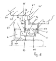
- Beim Ausführungsbeispiel nach
Fig. 8 ist das Dämpfungsteil 24 zwischen dem Federteller 9a und einer Innenwand 62 eines Aufnahmeraumes 63 eines Pumpengehäuses 64 angeordnet. Der Federteller 9a hat den radial nach außen gerichteten Flansch 56, der im Unterschied zum vorigen Ausführungsbeispiel wesentlich breiter ist und am radial äußeren Ende in einen Zylinderabschnitt 65 übergeht, an dem das Dämpfungsteil 24 anliegt. Der Zylinderabschnitt 65 ragt bis in den Bereich oberhalb des Gegenringes 4 und ist am freien Ende mit einem radial nach außen gerichteten Flansch 66 versehen, der an der Stirnseite des Dämpfungsteiles 24 anliegt und es axial sichert. Der Flansch 56 liegt mit axialem Abstand zum radial nach außen gerichteten Gehäuseflansch 10', mit dem das Gehäuse 1 am Boden 67 des Aufnahmeraumes 63 anliegt. Das Dämpfungsteil 24 hat axialen Abstand vom Flansch 10'. - Der Flansch 56 ragt radial so weit nach außen, dass er in Höhe des Gehäuseflansches 10' liegt.
- Die Druckfeder 7 erstreckt sich zwischen dem Flansch 56 und dem radial nach außen gerichteten Flansch 59 des Federtellers 9b. Die Druckfeder 7 liegt auf den Zylinderabschnitten 53, 60 der beiden Federteller 9a, 9b auf.
- Im Übrigen ist diese Ausführungsform gleich ausgebildet wie das vorige Ausführungsbeispiel.
- Die Gleitringdichtung nach
Fig. 9 hat das Dämpfungsteil 68, das im Unterschied zum Dämpfungsteil 24 als Federabschnitt keine Rippen und Vertiefungen, sondern zylindrische Federabschnitte aufweist. Das Ausführungsbeispiel ist bis auf die Gestaltung des Dämpfungsteiles gleich ausgebildet wie die Ausführungsform gemäßFig. 2 . Das Dämpfungsteil 68 ist als Ringnapf ausgebildet, der einen radial äußeren Zylindermantel 69 und einen radial inneren Zylindermantel 70 aufweist, die durch einen radialen Boden 71 ineinander übergehen. Die beiden Zylindermäntel 69, 70 liegen koaxial zueinander und zur abzudichtenden Welle 5. Der äußere Zylindermantel 69 ist axial länger als der innere Zylindermantel 70. Der äußere Zylindermantel 69 ragt in das Gehäuse 1 und liegt an der Innenwand des Gehäusemantels 10 unter radialer Vorspannung an. Der kürzere Zylindermantel 70 liegt auf dem zylindrischen Abschnitt 41 der Sekundärdichtung 6 auf und belastet diese in radialer Richtung. Der Zylindermantel 70 hat geringen axialen Abstand vom Zylinderabschnitt 45 des Federtellers 9. Der in einer Radialebene liegende Boden 71 des Dämpfungsteiles 68 liegt in Höhe der Schulterfläche 58 des Gleitrings 3. - Der Zylindermantel 69 ist radial elastisch nachgiebig, so dass er entsprechende Radialbewegungen des Gleitringes 3 durch elastische Verformung auffangen kann. Die Geräuschentwicklung wird dadurch vermieden. Wie beim Dämpfungsteil 24 trägt die vorgesehene Mikroreibung zu einer optimalen Dämpfung bei.
- Die Gleitringdichtung nach
Fig. 10 entspricht im Wesentlichen dem Ausführungsbeispiel nachFig. 9 . Das Dämpfungsteil 68 hat den zylindrischen Außenmantel 69, der in der beschriebenen Weise unter radialer Vorspannung an der Innenseite des Mantels 10 des Gehäuses 1 anliegt. Im Unterschied zum vorigen Ausführungsbeispiel erstreckt sich der radial innen liegende Zylindermantel 70 nicht in gleiche Richtung wie der äußere Zylindermantel 69, sondern in Richtung auf den Gegenring 4. Der innere Zylindermantel 70 liegt auf der äußeren Mantelfläche 19 des Gleitringes 3 im Bereich außerhalb der Vertiefung 40 auf. Der Zylindermantel 69 ist aufgrund seiner axialen Länge ausreichend federelastisch, so dass er entsprechend radial nachgeben kann. - Die Gleitringdichtung ist im Übrigen gleich ausgebildet wie das Ausführungsbeispiel nach
Fig. 9 . -
Fig. 11 zeigt ein Dämpfungsteil 68, dessen Boden 71 im Axialschnitt teilkreisförmig gekrümmt ausgebildet ist. Der radial innere Zylindermantel 70 liegt auf dem Zylinderabschnitt 45 des Federtellers 9 unter radialer Vorspannung auf. - Bei den beschriebenen Ausführungsbeispielen nach den
Fig. 9 bis 11 kann der äußere Zylindermantel 69 entsprechend denFig. 12 ,12a ,12b und13 wellenförmig über seinen Umfang profiliert sein, so dass der Zylindermantel lediglich mit den rippenartigen Erhöhungen am Gehäusemantel 10 anliegt. - Die erfindungsgemäße Gleitringdichtung nach
Fig. 14 entspricht in ihrem Aufbau im Wesentlichen dem Ausführungsbeispiel nachFig. 1 . Der Unterschied liegt in der Ausbildung und Anordnung des Dämpfungsteils 24. Es stützt sich axial auf dem zylindrischen Teil 21 des Federtellers 9 ab, der auf der Sekundärdichtung 6 sitzt und an dem die Druckfeder 7 angreift. Das Dämpfungsteil 24 stützt sich außerdem am radial nach außen ragenden Rand 10' des Gehäuses 1 ab. - Das Dämpfungsteil 24 hat die in den
Fig. 15 und 16 dargestellte Ausbildung. Es ist als geschlossener Ring ausgebildet und hat einen Ringteil 75, der als flache Ringscheibe ausgebildet ist. An der Innenseite 76 des Ringteils 75 sind über den Umfang verteilt Federzungen 77 vorgesehen, die vorteilhaft gleich ausgebildet sind und vorteilhaft gleichen Abstand voneinander haben. Die Federzungen ragen schräg nach innen und werden in der Einbaulage des Dämpfungsteils 24 elastisch verformt. - Bei der erfindungsgemäßen Gleitringdichtung nach
Fig. 14 liegen die Federzungen 77 unter elastischer Verformung am zylindrischen Teil 21 des Federtellers 9 an. Mit der flachen Ringscheibe 75 liegt das Dämpfungsteil 24 am radial nach außen gerichteten Rand 10' des Gehäuses 1 an. Die Federzungen 77 stehen in Richtung auf den Boden 8 des Gehäuses 1 geringfügig über den Ringsteg 9' des Federtellers 9 vor. Die Federzungen 7 haben außerdem radialen Abstand von der Innenwand des Außenmantels 10 des Gehäuses 1. - Das Dämpfungsteil 24 ist wiederum so eingebaut, dass die Federzungen 77 die Mikroreibung zur Geräuschdämpfung in Umfangsrichtung erzeugen. Diese Umfangsrichtung ist, wie schon bei den Dämpfungsteilen 24 gemäß den
Fig. 12 ,12a ,12b und13 , die Hauptrichtung für die Erzeugung der Mikroreibung, während die Axialrichtung der Gleitringdichtung für die Schwingungsdämpfung keine Rolle spielt. - Die erfindungsgemäße Gleitringdichtung nach
Fig. 17 ist gleich ausgebildet wie die Gleitringdichtung nachFig. 14 . Lediglich das Dämpfungsteil 24 hat eine andere Ausbildung und Einbaulage. Wie dieFig. 18 und 19 zeigen, sind die Federzungen 77 des Dämpfungsteils 24 an der Außenseite des scheibenförmigen Ringteiles 75 vorgesehen. Die Federzungen 77 sind schräg nach außen gerichtet. Sie liegen in der Einbaulage unter elastischer Verformung an der Innenseite des Außenmantels 10 des Gehäuses 1 an (Fig. 17 ). Die Federzungen 77 erstrecken sich vom Ringteil 75 aus geringfügig über den radial nach außen gerichteten freien Rand 10' des Gehäuses 1. Die Federzungen 77 haben radialen Abstand vom Federteller 9. - Der Ringteil 75 des Dämpfungsteiles 24 liegt am radialen Ringsteg 9' des Federtellers 9 unter der Kraft der Druckfeder 7 an. Der Ringteil 75 kann sich bis zum radial innen liegenden Zylinderteil 20 des Federtellers 9 erstrecken.
- Bei dieser Ausführungsform liegen die elastischen Federzungen 77 unter elastischer Vorspannung am Gehäuse 1 an, während der in einer Radialebene liegende Ringteil 75 am radialen Ringsteg 9' des Federtellers 9 anliegt.
-
Fig. 20 zeigt eine Gleitringdichtung, die im Wesentlichen gleich ausgebildet ist wie die Gleitringdichtung gemäß denFig. 14 oder17 . Lediglich das Dämpfungsteil 24 hat eine andere Ausbildung. Das Dämpfungsteil 24 hat zwei scheibenförmige Ringteile 78, 79, die jeweils in einer Radialebene der Gleitringdichtung liegen und durch einen als Federteil dienenden Konusteil 80 ineinander übergehen. Der radial äußere Ringteil 78 liegt am freien Rand 10' des Gehäuses 1 an. Der radial innere Ringteil 79 liegt am radialen Ringsteg 9' des Federtellers 9 an. Der Ringteil 79 wird durch die Druckfeder 7 axial gegen den radialen Ringsteg 9' des Federtellers 9 gedrückt. - Bei dieser Ausführungsform entsteht die Mikroreibung zwischen den radial sich erstreckenden Ringteilen 78, 79 des Dämpfungsteils 24 und dem radialen Rand 10' des Gehäuses 1 sowie dem radialen Ringsteg 9' des Federtellers 9.
- Bei der Gleitringdichtung nach
Fig. 21 hat das Dämpfungsteil 24 zylindrische Ringteile 78', 79'. Das Dämpfungsteil 24 ist so angeordnet, dass der Ringteil 78' auf der Außenseite des Zylinderteils 21 des Federtellers 9 und der Ringteil 79' an der Innenseite des Außenmantels 10 des Gehäuses 1 anliegt. Die zylindrischen Ringteile 78' und 79' sind durch den Konusteil 80 miteinander verbunden. Im Übrigen ist die Gleitringdichtung gleich ausgebildet wie die Gleitringdichtung gemäßFig. 20 . - Die Ringteile 69, 70; 77, 78, 79; 78', 79' können segmentiert sein.
- Bei der Gleitringdichtung nach
Fig. 22 ist das Dämpfungsteil 24 einstückig mit dem Federteller 9 ausgebildet. Die Gleitringdichtung ist weitgehend gleich aufgebaut wie die Gleitringdichtung nachFig. 1 . Der radial nach außen gerichtete Ringrand des Federtellers 9 bildet das Dämpfungsteil 24, das vom Rückhalteelement 48 umgeben ist. Es ist entsprechend der Ausführungsform gemäßFig. 4 ausgebildet und ist mit seinem Flansch 51 am freien Rand 10' des Gehäuses 1 befestigt. Am radial nach innen ragenden Flansch 49 des Rückhalteelementes 48 stützt sich ein Federteil 81 ab, das sich zwischen dem Flansch 49 und dem Dämpfungsteil 24 erstreckt und unter axialer Vorspannung an diesen beiden Teilen anliegt. Der Federteil 81 kann beispielsweise eine Wellfeder sein. Grundsätzlich ist es auch möglich, über den Umfang des Dämpfungsteils 24 verteilt Druckfedern anzuordnen, die sich zwischen dem Flansch 49 und dem Dämpfungsteil 24 erstrecken. Die von der Druckfeder 7 ausgeübte Druckkraft ist höher als die vom Federteil 81 ausgeübte Federkraft. Dadurch ist sichergestellt, dass der Gleitring 3 und der Gegenring 4 mit der für die Abdichtung erforderlichen Axialkraft aneinander liegen.
Claims (4)
- Gleitringdichtung für eine Welle (5), mit wenigstens einer Halterung (2) für wenigstens eines der Dichtungselemente (3, 4), die durch einen Dichtring und einen Gegenring gebildet sind, die unter Axialkraft dichtend aneinander liegen, mit wenigstens einem Dämpfungsteil (24), das wenigstens ein geformtes Blechteil aufweist, das mit wenigstens einem elastisch verformbaren Federteil (77 ) versehen ist, der zur Erzeugung einer Mikroreibung zwischen dem Dämpfungsteil (24) und dem Abstützbereich unter Vorspannung abgestützt ist,
dadurch gekennzeichnet, dass die Halterung (2) den Gegenring (4) aufnimmt, der über die Halterung (2) drehfest mit der Welle (5) verbindbar ist, dass der Gegenring (4) auf einer ringförmigen, als Dichtung dienenden Manschette (30) sitzt, die zwischen einem zylindrischen Abschnitt (28) der Halterung (2) und einer zylindrischen Innenfläche (27) des Gegenringes (4) liegt und den Gegenring (4) in der Halterung (2) hält, dass das Dämpfungsteil (24) unter Zwischenlage eines Federtellers (9, 9a) und einer Sekundärdichtung (6) am Gleitring (3) anliegt, und dass der Federteil (77) eine von einem Ringteil (75) des Dämpfungsteiles (24) schräg abstehende Zunge ist, die in Einbaulage elastisch verformt ist und sich in Axialrichtung der Gleitringdichtung erstreckt. - Gleitringdichtung nach Anspruch 1,
dadurch gekennzeichnet, dass der Federtell (77), vorzugsweise unter radialer oder axialer Vorspannung, am Gehäuse (1) abgestützt ist. - Gleitringdichtung nach Anspruch 1,
dadurch gekennzeichnet, dass der Federteil (77) an einem Federteller (9) abgestützt ist. - Gleitringdichtung nach einem der Ansprüche 1 bis 3,
dadurch gekennzeichnet, dass zumindest der Federteil (77) teilweise aus dem Gehäuse (1) ragt.
Applications Claiming Priority (1)
| Application Number | Priority Date | Filing Date | Title |
|---|---|---|---|
| DE102009049093A DE102009049093A1 (de) | 2009-10-01 | 2009-10-01 | Gleitringdichtung |
Publications (2)
| Publication Number | Publication Date |
|---|---|
| EP2306052A1 EP2306052A1 (de) | 2011-04-06 |
| EP2306052B1 true EP2306052B1 (de) | 2014-04-30 |
Family
ID=43415227
Family Applications (1)
| Application Number | Title | Priority Date | Filing Date |
|---|---|---|---|
| EP10008648.7A Active EP2306052B1 (de) | 2009-10-01 | 2010-08-19 | Gleitringdichtung |
Country Status (8)
| Country | Link |
|---|---|
| US (1) | US9010764B2 (de) |
| EP (1) | EP2306052B1 (de) |
| JP (1) | JP5711926B2 (de) |
| CN (1) | CN102032347B (de) |
| BR (1) | BRPI1003806B1 (de) |
| CA (1) | CA2714981C (de) |
| DE (1) | DE102009049093A1 (de) |
| MX (1) | MX340195B (de) |
Families Citing this family (12)
| Publication number | Priority date | Publication date | Assignee | Title |
|---|---|---|---|---|
| WO2014173495A2 (de) | 2013-04-22 | 2014-10-30 | Carl Freudenberg Kg | Gleitringdichtung |
| CN106662254B (zh) * | 2014-07-24 | 2019-06-18 | 伊格尔工业股份有限公司 | 机械密封件 |
| EP3199846B1 (de) * | 2014-09-24 | 2019-05-15 | Eagle Industry Co., Ltd. | Mechanische dichtung |
| WO2016050534A1 (de) * | 2014-09-30 | 2016-04-07 | Siemens Aktiengesellschaft | Flüssigkeitsgekühlte elektrische maschine |
| WO2016076247A1 (ja) * | 2014-11-11 | 2016-05-19 | Nok株式会社 | 密封装置 |
| US11739844B2 (en) | 2016-09-14 | 2023-08-29 | Eagle Industry Co., Ltd. | Mechanical seal |
| EP3513102B1 (de) | 2016-09-16 | 2020-11-04 | Flowserve Management Company | Radial und axial selbstausrichtender spaltdichtungsring |
| EP3568620B1 (de) * | 2017-01-12 | 2021-05-05 | Flowserve Management Company | Vorrichtung zur montage von geteilten dichtungsringen |
| CN107143615A (zh) * | 2017-06-29 | 2017-09-08 | 湖北威能达驱动技术系统有限公司 | 一种弹片预应力密封组合 |
| DE102017219190B4 (de) * | 2017-10-26 | 2022-12-29 | Eagleburgmann Germany Gmbh & Co. Kg | Gasgeschmierte Gleitringdichtung mit verbessertem Verschmutzungsschutz |
| WO2019163726A1 (ja) * | 2018-02-21 | 2019-08-29 | イーグル工業株式会社 | メカニカルシール |
| FR3095847B1 (fr) * | 2019-05-06 | 2021-08-13 | Cyclam | garniture d’étanchéité COMPACTE pour assurer l’étanchéité entre un arbre rotatif et un corps stationnaire d’une machine |
Family Cites Families (22)
| Publication number | Priority date | Publication date | Assignee | Title |
|---|---|---|---|---|
| DE19860250C1 (de) | 1998-12-24 | 2000-11-02 | Daimler Chrysler Ag | Zahnräderwechselgetriebe mit zwei im Kraftfluß parallel zueinander angeordneten Teilgetrieben |
| US3515394A (en) | 1964-06-05 | 1970-06-02 | Sealol | Vibration damping means for resilient convoluted members |
| JPS5465249A (en) | 1977-11-01 | 1979-05-25 | Akira Washida | Mechanical seal |
| JPS57153854A (en) | 1981-03-12 | 1982-09-22 | Hitachi Shipbuilding Eng Co | Hanger for vessel of powdered and granular body |
| JPS6145405Y2 (de) * | 1981-03-20 | 1986-12-20 | ||
| JPS60194668A (ja) | 1984-03-16 | 1985-10-03 | Hitachi Ltd | 画像読取センサ |
| JPS60194668U (ja) * | 1984-06-05 | 1985-12-25 | イーグル工業株式会社 | メカニカルシ−ル用緩衝ゴム |
| JPH0229313Y2 (de) * | 1985-11-06 | 1990-08-07 | ||
| US6311983B1 (en) * | 1989-09-26 | 2001-11-06 | The Boeing Company | Combination static lift-off face contact seal and floating ring shaft seal |
| JPH09292034A (ja) | 1996-04-25 | 1997-11-11 | Mitsubishi Heavy Ind Ltd | メカニカルシール |
| US5873574A (en) * | 1996-07-18 | 1999-02-23 | John Crane Sealol Inc. | Bellows seal with reverse pressure capability |
| DE19739398A1 (de) * | 1997-09-09 | 1999-03-11 | Kaco Gmbh Co | Dichtung |
| JP2000074226A (ja) * | 1998-08-27 | 2000-03-14 | Eagle Ind Co Ltd | メカニカルシール |
| FR2787851B1 (fr) * | 1998-12-24 | 2001-03-23 | Snecma | Amortisseur de joint dynamique |
| US6398223B1 (en) * | 2000-08-21 | 2002-06-04 | John Crane Inc. | Mechanical face seal |
| JP2002195420A (ja) * | 2001-12-26 | 2002-07-10 | Eagle Ind Co Ltd | 回転環の変形制御方法 |
| DE20206927U1 (de) | 2002-05-01 | 2003-09-04 | Dassler Puma Sportschuh | Dämpfungselement für einen Schuh |
| JP3966474B2 (ja) * | 2003-10-02 | 2007-08-29 | 日産自動車株式会社 | シールリング及びシール装置 |
| SE527765C2 (sv) | 2004-10-21 | 2006-05-30 | Roplan Dev Ct Ab | Stödring och axelgenomföring |
| DE102005036338A1 (de) * | 2005-07-29 | 2007-02-15 | Wilo Ag | Gleitringdichtung |
| US8128097B2 (en) * | 2006-06-08 | 2012-03-06 | Eagle Industry Co., Ltd. | Mechanical seal |
| JP4793151B2 (ja) * | 2006-07-18 | 2011-10-12 | いすゞ自動車株式会社 | メカニカルシール装置及びウォーターポンプ |
-
2009
- 2009-10-01 DE DE102009049093A patent/DE102009049093A1/de not_active Withdrawn
-
2010
- 2010-08-19 EP EP10008648.7A patent/EP2306052B1/de active Active
- 2010-09-20 CA CA2714981A patent/CA2714981C/en not_active Expired - Fee Related
- 2010-09-25 US US12/890,604 patent/US9010764B2/en not_active Expired - Fee Related
- 2010-09-28 CN CN201010297809.7A patent/CN102032347B/zh active Active
- 2010-09-30 JP JP2010221790A patent/JP5711926B2/ja active Active
- 2010-09-30 MX MX2010010739A patent/MX340195B/es active IP Right Grant
- 2010-10-01 BR BRPI1003806-0A patent/BRPI1003806B1/pt not_active IP Right Cessation
Also Published As
| Publication number | Publication date |
|---|---|
| EP2306052A1 (de) | 2011-04-06 |
| JP2011075102A (ja) | 2011-04-14 |
| US20110079961A1 (en) | 2011-04-07 |
| CN102032347B (zh) | 2015-07-08 |
| JP5711926B2 (ja) | 2015-05-07 |
| CN102032347A (zh) | 2011-04-27 |
| US9010764B2 (en) | 2015-04-21 |
| MX2010010739A (es) | 2011-05-04 |
| BRPI1003806A2 (pt) | 2013-02-13 |
| CA2714981A1 (en) | 2011-04-01 |
| CA2714981C (en) | 2017-04-04 |
| BRPI1003806B1 (pt) | 2020-02-11 |
| DE102009049093A1 (de) | 2011-04-07 |
| MX340195B (es) | 2016-06-30 |
Similar Documents
| Publication | Publication Date | Title |
|---|---|---|
| EP2306052B1 (de) | Gleitringdichtung | |
| DE102007050349B4 (de) | Dichtungsanordnung für den Hochdruckbereich | |
| EP3596363B1 (de) | Dichtungsanordnung | |
| EP1585906B1 (de) | Anordnung zur sicherung eines sprengringes | |
| DE3219156C2 (de) | ||
| EP2817539B1 (de) | Radialwellendichtung | |
| EP0493731B1 (de) | Elastisches Lager | |
| EP2199639A2 (de) | Scheibenbremse für ein Nutzfahrzeug | |
| DE102012222269A1 (de) | Reibungskupplung | |
| EP2618032B1 (de) | Wellendichtung, insbesondere Radialwellendichtung | |
| DE112014001037B4 (de) | Reibungskupplung | |
| DE10113442C2 (de) | Lageranordnung für ein Wellenlager | |
| EP1691104A1 (de) | Elastisches Lager | |
| DE19648602A1 (de) | Dichtungsanordnung | |
| DE4225556A1 (de) | Zwischen radial nach innen weisenden Vorsprüngen einer Zylinderfläche abgestützte Stangenführung | |
| DE102007053724A1 (de) | Kupplungsvorrichtung | |
| DE10005547A1 (de) | Schwingungsdämpfungseinrichtung | |
| EP3277977B1 (de) | Axialdämpfer | |
| EP1841981A1 (de) | Scheibenbremse | |
| EP1747384B1 (de) | Lageranordnung bestehend aus einem lager und einem lagerträger | |
| DE102012220839A1 (de) | Rampensystem für eine Nachstelleinrichtung einer Reibungskupplung | |
| EP3234401B1 (de) | Scheibenbremse für ein nutzfahrzeug | |
| EP2875251A1 (de) | Ausrücklageranordnung | |
| EP3417192B1 (de) | Wellendichtung | |
| DE102016015553B4 (de) | Radialwellendichtung |
Legal Events
| Date | Code | Title | Description |
|---|---|---|---|
| PUAI | Public reference made under article 153(3) epc to a published international application that has entered the european phase |
Free format text: ORIGINAL CODE: 0009012 |
|
| AK | Designated contracting states |
Kind code of ref document: A1 Designated state(s): AL AT BE BG CH CY CZ DE DK EE ES FI FR GB GR HR HU IE IS IT LI LT LU LV MC MK MT NL NO PL PT RO SE SI SK SM TR |
|
| AX | Request for extension of the european patent |
Extension state: BA ME RS |
|
| 17P | Request for examination filed |
Effective date: 20111006 |
|
| 17Q | First examination report despatched |
Effective date: 20120426 |
|
| GRAP | Despatch of communication of intention to grant a patent |
Free format text: ORIGINAL CODE: EPIDOSNIGR1 |
|
| INTG | Intention to grant announced |
Effective date: 20131121 |
|
| GRAS | Grant fee paid |
Free format text: ORIGINAL CODE: EPIDOSNIGR3 |
|
| GRAA | (expected) grant |
Free format text: ORIGINAL CODE: 0009210 |
|
| AK | Designated contracting states |
Kind code of ref document: B1 Designated state(s): AL AT BE BG CH CY CZ DE DK EE ES FI FR GB GR HR HU IE IS IT LI LT LU LV MC MK MT NL NO PL PT RO SE SI SK SM TR |
|
| REG | Reference to a national code |
Ref country code: GB Ref legal event code: FG4D Free format text: NOT ENGLISH Ref country code: CH Ref legal event code: EP |
|
| REG | Reference to a national code |
Ref country code: AT Ref legal event code: REF Ref document number: 665367 Country of ref document: AT Kind code of ref document: T Effective date: 20140515 |
|
| REG | Reference to a national code |
Ref country code: IE Ref legal event code: FG4D Free format text: LANGUAGE OF EP DOCUMENT: GERMAN |
|
| REG | Reference to a national code |
Ref country code: DE Ref legal event code: R096 Ref document number: 502010006774 Country of ref document: DE Effective date: 20140612 |
|
| REG | Reference to a national code |
Ref country code: LT Ref legal event code: MG4D |
|
| REG | Reference to a national code |
Ref country code: NL Ref legal event code: VDEP Effective date: 20140430 |
|
| PG25 | Lapsed in a contracting state [announced via postgrant information from national office to epo] |
Ref country code: NL Free format text: LAPSE BECAUSE OF FAILURE TO SUBMIT A TRANSLATION OF THE DESCRIPTION OR TO PAY THE FEE WITHIN THE PRESCRIBED TIME-LIMIT Effective date: 20140430 Ref country code: IS Free format text: LAPSE BECAUSE OF FAILURE TO SUBMIT A TRANSLATION OF THE DESCRIPTION OR TO PAY THE FEE WITHIN THE PRESCRIBED TIME-LIMIT Effective date: 20140830 Ref country code: CY Free format text: LAPSE BECAUSE OF FAILURE TO SUBMIT A TRANSLATION OF THE DESCRIPTION OR TO PAY THE FEE WITHIN THE PRESCRIBED TIME-LIMIT Effective date: 20140430 Ref country code: BG Free format text: LAPSE BECAUSE OF FAILURE TO SUBMIT A TRANSLATION OF THE DESCRIPTION OR TO PAY THE FEE WITHIN THE PRESCRIBED TIME-LIMIT Effective date: 20140730 Ref country code: FI Free format text: LAPSE BECAUSE OF FAILURE TO SUBMIT A TRANSLATION OF THE DESCRIPTION OR TO PAY THE FEE WITHIN THE PRESCRIBED TIME-LIMIT Effective date: 20140430 Ref country code: LT Free format text: LAPSE BECAUSE OF FAILURE TO SUBMIT A TRANSLATION OF THE DESCRIPTION OR TO PAY THE FEE WITHIN THE PRESCRIBED TIME-LIMIT Effective date: 20140430 Ref country code: NO Free format text: LAPSE BECAUSE OF FAILURE TO SUBMIT A TRANSLATION OF THE DESCRIPTION OR TO PAY THE FEE WITHIN THE PRESCRIBED TIME-LIMIT Effective date: 20140730 Ref country code: GR Free format text: LAPSE BECAUSE OF FAILURE TO SUBMIT A TRANSLATION OF THE DESCRIPTION OR TO PAY THE FEE WITHIN THE PRESCRIBED TIME-LIMIT Effective date: 20140731 |
|
| PG25 | Lapsed in a contracting state [announced via postgrant information from national office to epo] |
Ref country code: PL Free format text: LAPSE BECAUSE OF FAILURE TO SUBMIT A TRANSLATION OF THE DESCRIPTION OR TO PAY THE FEE WITHIN THE PRESCRIBED TIME-LIMIT Effective date: 20140430 Ref country code: LV Free format text: LAPSE BECAUSE OF FAILURE TO SUBMIT A TRANSLATION OF THE DESCRIPTION OR TO PAY THE FEE WITHIN THE PRESCRIBED TIME-LIMIT Effective date: 20140430 Ref country code: SE Free format text: LAPSE BECAUSE OF FAILURE TO SUBMIT A TRANSLATION OF THE DESCRIPTION OR TO PAY THE FEE WITHIN THE PRESCRIBED TIME-LIMIT Effective date: 20140430 Ref country code: HR Free format text: LAPSE BECAUSE OF FAILURE TO SUBMIT A TRANSLATION OF THE DESCRIPTION OR TO PAY THE FEE WITHIN THE PRESCRIBED TIME-LIMIT Effective date: 20140430 Ref country code: ES Free format text: LAPSE BECAUSE OF FAILURE TO SUBMIT A TRANSLATION OF THE DESCRIPTION OR TO PAY THE FEE WITHIN THE PRESCRIBED TIME-LIMIT Effective date: 20140430 |
|
| PG25 | Lapsed in a contracting state [announced via postgrant information from national office to epo] |
Ref country code: PT Free format text: LAPSE BECAUSE OF FAILURE TO SUBMIT A TRANSLATION OF THE DESCRIPTION OR TO PAY THE FEE WITHIN THE PRESCRIBED TIME-LIMIT Effective date: 20140901 |
|
| PG25 | Lapsed in a contracting state [announced via postgrant information from national office to epo] |
Ref country code: RO Free format text: LAPSE BECAUSE OF FAILURE TO SUBMIT A TRANSLATION OF THE DESCRIPTION OR TO PAY THE FEE WITHIN THE PRESCRIBED TIME-LIMIT Effective date: 20140430 Ref country code: EE Free format text: LAPSE BECAUSE OF FAILURE TO SUBMIT A TRANSLATION OF THE DESCRIPTION OR TO PAY THE FEE WITHIN THE PRESCRIBED TIME-LIMIT Effective date: 20140430 Ref country code: SK Free format text: LAPSE BECAUSE OF FAILURE TO SUBMIT A TRANSLATION OF THE DESCRIPTION OR TO PAY THE FEE WITHIN THE PRESCRIBED TIME-LIMIT Effective date: 20140430 Ref country code: DK Free format text: LAPSE BECAUSE OF FAILURE TO SUBMIT A TRANSLATION OF THE DESCRIPTION OR TO PAY THE FEE WITHIN THE PRESCRIBED TIME-LIMIT Effective date: 20140430 Ref country code: CZ Free format text: LAPSE BECAUSE OF FAILURE TO SUBMIT A TRANSLATION OF THE DESCRIPTION OR TO PAY THE FEE WITHIN THE PRESCRIBED TIME-LIMIT Effective date: 20140430 |
|
| REG | Reference to a national code |
Ref country code: DE Ref legal event code: R097 Ref document number: 502010006774 Country of ref document: DE |
|
| PLBE | No opposition filed within time limit |
Free format text: ORIGINAL CODE: 0009261 |
|
| STAA | Information on the status of an ep patent application or granted ep patent |
Free format text: STATUS: NO OPPOSITION FILED WITHIN TIME LIMIT |
|
| PG25 | Lapsed in a contracting state [announced via postgrant information from national office to epo] |
Ref country code: LU Free format text: LAPSE BECAUSE OF FAILURE TO SUBMIT A TRANSLATION OF THE DESCRIPTION OR TO PAY THE FEE WITHIN THE PRESCRIBED TIME-LIMIT Effective date: 20140819 Ref country code: MC Free format text: LAPSE BECAUSE OF FAILURE TO SUBMIT A TRANSLATION OF THE DESCRIPTION OR TO PAY THE FEE WITHIN THE PRESCRIBED TIME-LIMIT Effective date: 20140430 |
|
| REG | Reference to a national code |
Ref country code: CH Ref legal event code: PL |
|
| 26N | No opposition filed |
Effective date: 20150202 |
|
| PG25 | Lapsed in a contracting state [announced via postgrant information from national office to epo] |
Ref country code: CH Free format text: LAPSE BECAUSE OF NON-PAYMENT OF DUE FEES Effective date: 20140831 Ref country code: LI Free format text: LAPSE BECAUSE OF NON-PAYMENT OF DUE FEES Effective date: 20140831 Ref country code: BE Free format text: LAPSE BECAUSE OF NON-PAYMENT OF DUE FEES Effective date: 20140831 |
|
| REG | Reference to a national code |
Ref country code: DE Ref legal event code: R097 Ref document number: 502010006774 Country of ref document: DE Effective date: 20150202 |
|
| REG | Reference to a national code |
Ref country code: IE Ref legal event code: MM4A |
|
| PG25 | Lapsed in a contracting state [announced via postgrant information from national office to epo] |
Ref country code: SI Free format text: LAPSE BECAUSE OF FAILURE TO SUBMIT A TRANSLATION OF THE DESCRIPTION OR TO PAY THE FEE WITHIN THE PRESCRIBED TIME-LIMIT Effective date: 20140430 |
|
| PG25 | Lapsed in a contracting state [announced via postgrant information from national office to epo] |
Ref country code: IE Free format text: LAPSE BECAUSE OF NON-PAYMENT OF DUE FEES Effective date: 20140819 |
|
| PG25 | Lapsed in a contracting state [announced via postgrant information from national office to epo] |
Ref country code: SM Free format text: LAPSE BECAUSE OF FAILURE TO SUBMIT A TRANSLATION OF THE DESCRIPTION OR TO PAY THE FEE WITHIN THE PRESCRIBED TIME-LIMIT Effective date: 20140430 |
|
| PG25 | Lapsed in a contracting state [announced via postgrant information from national office to epo] |
Ref country code: MT Free format text: LAPSE BECAUSE OF FAILURE TO SUBMIT A TRANSLATION OF THE DESCRIPTION OR TO PAY THE FEE WITHIN THE PRESCRIBED TIME-LIMIT Effective date: 20140430 |
|
| PG25 | Lapsed in a contracting state [announced via postgrant information from national office to epo] |
Ref country code: HU Free format text: LAPSE BECAUSE OF FAILURE TO SUBMIT A TRANSLATION OF THE DESCRIPTION OR TO PAY THE FEE WITHIN THE PRESCRIBED TIME-LIMIT; INVALID AB INITIO Effective date: 20100819 Ref country code: TR Free format text: LAPSE BECAUSE OF FAILURE TO SUBMIT A TRANSLATION OF THE DESCRIPTION OR TO PAY THE FEE WITHIN THE PRESCRIBED TIME-LIMIT Effective date: 20140430 |
|
| REG | Reference to a national code |
Ref country code: FR Ref legal event code: PLFP Year of fee payment: 7 |
|
| REG | Reference to a national code |
Ref country code: AT Ref legal event code: MM01 Ref document number: 665367 Country of ref document: AT Kind code of ref document: T Effective date: 20150819 |
|
| PG25 | Lapsed in a contracting state [announced via postgrant information from national office to epo] |
Ref country code: AT Free format text: LAPSE BECAUSE OF NON-PAYMENT OF DUE FEES Effective date: 20150819 |
|
| REG | Reference to a national code |
Ref country code: FR Ref legal event code: PLFP Year of fee payment: 8 |
|
| PG25 | Lapsed in a contracting state [announced via postgrant information from national office to epo] |
Ref country code: MK Free format text: LAPSE BECAUSE OF FAILURE TO SUBMIT A TRANSLATION OF THE DESCRIPTION OR TO PAY THE FEE WITHIN THE PRESCRIBED TIME-LIMIT Effective date: 20140430 |
|
| REG | Reference to a national code |
Ref country code: FR Ref legal event code: PLFP Year of fee payment: 9 |
|
| PG25 | Lapsed in a contracting state [announced via postgrant information from national office to epo] |
Ref country code: AL Free format text: LAPSE BECAUSE OF FAILURE TO SUBMIT A TRANSLATION OF THE DESCRIPTION OR TO PAY THE FEE WITHIN THE PRESCRIBED TIME-LIMIT Effective date: 20140430 |
|
| REG | Reference to a national code |
Ref country code: DE Ref legal event code: R081 Ref document number: 502010006774 Country of ref document: DE Owner name: KACO GMBH + CO. KG, DE Free format text: FORMER OWNER: KACO GMBH + CO. KG, 74072 HEILBRONN, DE Ref country code: DE Ref legal event code: R082 Ref document number: 502010006774 Country of ref document: DE Representative=s name: JACKISCH-KOHL UND KOHL, DE |
|
| PGFP | Annual fee paid to national office [announced via postgrant information from national office to epo] |
Ref country code: GB Payment date: 20200813 Year of fee payment: 11 |
|
| PGFP | Annual fee paid to national office [announced via postgrant information from national office to epo] |
Ref country code: IT Payment date: 20200805 Year of fee payment: 11 |
|
| GBPC | Gb: european patent ceased through non-payment of renewal fee |
Effective date: 20210819 |
|
| PG25 | Lapsed in a contracting state [announced via postgrant information from national office to epo] |
Ref country code: IT Free format text: LAPSE BECAUSE OF NON-PAYMENT OF DUE FEES Effective date: 20210819 Ref country code: GB Free format text: LAPSE BECAUSE OF NON-PAYMENT OF DUE FEES Effective date: 20210819 |
|
| PGFP | Annual fee paid to national office [announced via postgrant information from national office to epo] |
Ref country code: FR Payment date: 20230620 Year of fee payment: 14 |
|
| PGFP | Annual fee paid to national office [announced via postgrant information from national office to epo] |
Ref country code: DE Payment date: 20230821 Year of fee payment: 14 |