EP2306052B1 - Joint mécanique - Google Patents
Joint mécanique Download PDFInfo
- Publication number
- EP2306052B1 EP2306052B1 EP10008648.7A EP10008648A EP2306052B1 EP 2306052 B1 EP2306052 B1 EP 2306052B1 EP 10008648 A EP10008648 A EP 10008648A EP 2306052 B1 EP2306052 B1 EP 2306052B1
- Authority
- EP
- European Patent Office
- Prior art keywords
- ring
- damping
- spring
- housing
- damping member
- Prior art date
- Legal status (The legal status is an assumption and is not a legal conclusion. Google has not performed a legal analysis and makes no representation as to the accuracy of the status listed.)
- Active
Links
- 238000013016 damping Methods 0.000 claims description 131
- 238000007789 sealing Methods 0.000 claims description 9
- 239000002184 metal Substances 0.000 claims description 5
- 230000006835 compression Effects 0.000 description 19
- 238000007906 compression Methods 0.000 description 19
- 210000002105 tongue Anatomy 0.000 description 13
- 230000013011 mating Effects 0.000 description 12
- 238000009434 installation Methods 0.000 description 8
- 230000000694 effects Effects 0.000 description 4
- 230000005489 elastic deformation Effects 0.000 description 4
- 230000004323 axial length Effects 0.000 description 3
- 238000000576 coating method Methods 0.000 description 3
- 239000011248 coating agent Substances 0.000 description 2
- 229910000639 Spring steel Inorganic materials 0.000 description 1
- 229910000831 Steel Inorganic materials 0.000 description 1
- 230000006978 adaptation Effects 0.000 description 1
- 230000002411 adverse Effects 0.000 description 1
- 230000015572 biosynthetic process Effects 0.000 description 1
- 238000010276 construction Methods 0.000 description 1
- 230000007797 corrosion Effects 0.000 description 1
- 238000005260 corrosion Methods 0.000 description 1
- 238000004519 manufacturing process Methods 0.000 description 1
- 230000004048 modification Effects 0.000 description 1
- 238000012986 modification Methods 0.000 description 1
- 239000002245 particle Substances 0.000 description 1
- 238000007788 roughening Methods 0.000 description 1
- 230000003068 static effect Effects 0.000 description 1
- 239000010959 steel Substances 0.000 description 1
- 230000007704 transition Effects 0.000 description 1
- XLYOFNOQVPJJNP-UHFFFAOYSA-N water Substances O XLYOFNOQVPJJNP-UHFFFAOYSA-N 0.000 description 1
Images


Classifications
-
- F—MECHANICAL ENGINEERING; LIGHTING; HEATING; WEAPONS; BLASTING
- F16—ENGINEERING ELEMENTS AND UNITS; GENERAL MEASURES FOR PRODUCING AND MAINTAINING EFFECTIVE FUNCTIONING OF MACHINES OR INSTALLATIONS; THERMAL INSULATION IN GENERAL
- F16J—PISTONS; CYLINDERS; SEALINGS
- F16J15/00—Sealings
- F16J15/16—Sealings between relatively-moving surfaces
- F16J15/34—Sealings between relatively-moving surfaces with slip-ring pressed against a more or less radial face on one member
- F16J15/3464—Mounting of the seal
- F16J15/3476—Means for minimising vibrations of the slip-ring
Definitions
- the invention relates to a mechanical seal according to the preamble of claim 1.
- the invention has the object of providing the generic mechanical seal in such a way that it can be manufactured inexpensively and ensures effective noise reduction.
- the damping part has a shaped sheet metal part, which can be produced easily and inexpensively. Due to its dimensional stability, it can be easily installed in the mechanical seal.
- the sheet metal part ensures a long service life of the damping part.
- the damping part With the spring part, the damping part is supported under prestress. Due to the metallic design of the damping part, a targeted biasing force can be adjusted to achieve an optimally adapted to the application of the mechanical seal damping effect. Between the damping part and the support area creates a micro friction, which leads to the damping effect.
- the damping part suppresses even in the most extreme operating conditions Noise effective. It can be inexpensively manufactured and easily installed while ensuring a long service life.
- the mechanical seal is advantageously used in automotive engineering.
- the damping part has an outer jacket, which is supported on a wall of the installation space of the mechanical seal under radial bias.
- the spring part is provided over its circumference with a profiling, preferably a wave-shaped profiling. It ensures optimal damping on the one hand, and on the other hand, high stability of the damping part is achieved.
- the mechanical seal according to the invention is preferably used in water pumps for noise damping.
- the damping part in particular its spring part, is designed such that it generates a micro friction, which leads to an optimal noise damping.
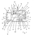
- Fig. 1 illustrated seal is designed as a mechanical seal, which has a cup-shaped housing 1, a sleeve-shaped holder 2, a slide ring 3 and a counter ring 4 in a known manner.
- the holder 2 is seated with a tubular inner shell 29 with a press fit on a shaft 5.
- the counter ring 4 is located with its facing away from the sliding ring 3 end face 31 at a radially outwardly projecting annular bottom 32 of the holder 2.
- the sliding ring 3 is rotatably mounted, while the counter-ring 4 rotates with the shaft 5.
- the sliding ring 3 is attached to a bellows formed as a secondary seal 6, which presses the slide ring 3 against the counter ring 4 under the force of a compression spring 7.
- the compression spring 7 rests with one end 7 'on a radial bottom 8 of the housing 1 and with its other end 7 "on a radially extending annular web 9' of a spring plate 9.
- the housing 1 has a cylindrical outer shell 10, the free edge 10 'is angled radially outward.
- the housing shell 10 adjoins the radially inwardly extending bottom 8, which adjoins a cylindrical inner shell 11. It goes about halfway along its axial length via a radially inwardly projecting shoulder surface 12 in a radially and axially further inside free inner shell portion 11 'over.
- the axis of the outer and inner shells 10 and 11 coincides with the axis of the shaft 5.
- the secondary seal 6 protrudes with a thickened inner edge 13 'of a cone part 12 in the outer shoulder 14 formed by the shoulder surface 12 and the shell portion 11'.
- a sleeve 15 is provided to compress the secondary seal 6 or its cone part 13 axially in the shoulder 14, which rests against the outside of the inner shell portion 11 'and an annular edge 13' of the cone part 13.
- the secondary seal 6 has in the illustration according to Fig. 1 approximately Z-shaped cross section with a cylindrical outer wall 16, which merges via a radially inwardly projecting annular portion 12 in the cone part 13.
- the sliding and the mating ring 3 and 4 are formed in a known manner and are therefore not described in detail.
- the secondary seal 6 lies with its annular portion 17 advantageously over its entire annular surface on the adjacent end face 18 of the slide ring 3. With its cylindrical outer wall 16, the secondary seal 6 bears against the outer jacket surface 19 of the sliding ring 3.
- the spring plate 9 has, similar to the secondary seal 6, Z-shaped cross-sectional shape.
- the radially inner part 20 of the spring plate 9 is cylindrical.
- the radially outer part 21 of the spring plate 9 is also cylindrical and surrounds the sliding ring over more than half its axial extent.
- the cylindrical part 21 of the spring plate 9 merges into a radially outwardly bent annular edge 22.
- a damping member 24 which in Fig. 12 is shown in more detail.
- the damping part 24 serves for vibration damping by generating micro friction. The micro-friction is generated between the damping part 24 and the inside of the outer shell 10 of the housing 1 and the outside of the cylinder part 21 of the spring plate 9.
- the inner jacket 29 of the holder 2 has an axially recessed cylinder portion 28 which connects to the ring bottom 32.
- the portion 28 has an axial extent which is slightly larger than the axial width of the counter-ring 4.
- the flange 32 is externally into a further cylinder portion 38 which extends coaxially to the portion 28 and has slightly smaller axial extent. This is equal to the axial width of the mating ring 4.
- At the cylindrical portion 28 of the holder 2 and the cylindrical inner surface 27 of the mating ring 4 is an annular sleeve 30 for sealing. Their axial extent is slightly smaller than that of the section 28 and slightly larger than that of the mating ring 4 or of the section 28 of the holder 2.
- the cuff 30 also serves to hold the mating ring 4 in the holder 2.
- the housing 1 protrudes with its cylindrical inner shell 11 with radial clearance in an annular space 33 which is formed between the sliding ring 3 and the inner shell 29 of the holder 2.
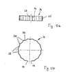
- the formation of the annular damping member 24 is based on Fig. 12 . 12a, 12b explained in more detail.
- the jacket 55 of the damping member 24 is profiled wavy. This will change the size of each other over the circumference Ribs 39 and recesses 25 formed.
- the ribs 39 and the recesses 25 are curved in radial section.
- the damping member 24 is located on the inner wall of the housing 1 and on the outside of the cylindrical part 21 of the spring plate 9 under prestress.
- Fig. 1 results, the damping member 24 protrudes axially from the housing 1 in the direction of the edge 22 of the secondary seal 6, which is located at an axial distance from the edge 10 'of the housing 1.
- the damping member 24 is located with its one end face on the ring edge 22.
- the other end of the damping member 24 has axial distance from the housing bottom. 8
- the damping member 24 has a larger number of ribs 39 and recesses 25.
- the damping part 24 is not closed. This results in an optimal elasticity of the damping part.
- the two ends 73, 74 of the damping member 24 may be spaced from each other. It is also possible that the ends 73, 74 overlap each other in the installation position. The two ends 73, 74 of the damping member 24 can move relative to each other in the circumferential direction of the damping member.
- the damping member 24 is formed by a shaped sheet metal part, which preferably consists of spring steel. Such a damping part can be manufactured easily and inexpensively.
- the damping member 24 is supported via the ribs 39 in the installed position radially on the housing 1 and the spring plate. By this radial support acting in the axial direction of the mechanical seal pressing or closing force acting on the slide ring 3, practically not affected. As a result, the tribological properties of the mechanical seal in the region of the sealing gap between the sliding ring 3 and the counter ring 4 by the installation of the damping member 24 remain unaffected. The damping member 24 effectively prevents the rotational or circumferential vibrations of the Sliding ring 3 during use, without affecting the sealing effect is adversely affected.
- the damping part 24 may be coated on at least one side, for example to obtain a corrosion protection, wear protection and the like. Such a coating can also be used in order to obtain a targeted micro friction between the damping part 24 and the housing 1 or the spring plate 9.
- the damping member 24 may also be completely sheathed.
- the damping member 24 may also be provided with corresponding surface structures to obtain desired micro-friction values.
- Such surface structures may be formed, for example, by roughening, laser-formed structures and the like.
- damping part 24 it is also possible, not the damping part 24, but to provide the corresponding counter surface on the housing 1 and the spring plate 9 with a corresponding coating and / or a corresponding surface structure.
- the holder 2 is advantageously formed by a steel part which is non-rotatably mounted on the shaft 5 to be sealed.
- the counter-ring 4 is used for dynamic sealing and rotates, since it is installed in the holder 2, together with the shaft 5.
- the sleeve 15 serves for the axial compression of the cone part 13 of the secondary seal 6, which forms the static seal of the mechanical seal.
- the compression spring 7 ensures that the slide ring 3 is pressed axially against the counter ring 4, so that the sealing gap between the slide ring 3 and the counter ring 4 is properly closed.
- the spring plate 9 serves as a press fit both for the sliding ring 3, which projects axially beyond the spring plate 9, as well as for the secondary seal. 6
- the damping member 24 is made of metal, preferably a molded spring plate. It requires only minimal installation space and is easy to manufacture.
- the damping member 24 is radially clamped between the jacket 21 of the spring plate 9 and the shell 10 of the housing 1, so that the ribs 39 of the damping member 24 rest under prestress on the spring plate 9 and the housing shell 10.
- the damping member 24 can absorb radial movements of the slide ring 3 by corresponding elastic deformation of the ribs 39 and the recesses 25.
- the described micro friction of the damping member 24 also leads to an excellent damping effect.
- the ribs 39 and the recesses 25 need not be provided over the entire axial width of the damping member 24.
- the ribs 39 and the recesses 25 of the profiled shell 55 extend only over half the axial width of the shell 55. They go over oblique intermediate portion 34 in a narrow cylinder portion 35 over.
- the depressions 25 are advantageously so deep that, in axial section according to Fig. 13 seen, the inner side 36 of the cylinder portion 35 also forms the lowest point of the recess 25 on the inside. Even with such a design is achieved with the damping member 24 excellent noise attenuation by micro friction.
- ribs 39 and recesses 25 may be provided in this embodiment, spaced apart tongues which are distributed over the circumference of the damping member 24.
- the cylinder portion 35 may consist of individual, circumferentially spaced behind one another tongues.
- the damping part 24 can be correspondingly Fig. 12 . 12a . 12b or Fig. 13 be educated.
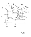
- Fig. 2 shows a mechanical seal
- the sliding ring 3 is provided on its outer circumferential surface 19 with a recess 40 which is open to the end face 18.
- the secondary seal 6 engages. It has a cylindrical portion 41 which fills the depression and merges into a spring part 42 which is bent in a part-circular manner in axial section. It merges into a ring disk section 43 lying in a radial plane, with which the secondary seal 6 rests against the inside of the bottom 8 of the housing 1.
- the secondary seal 6 is formed so that the arcuate spring member is biased and thereby presses the sliding ring 3 against the counter ring 4. He sits with the interposition of the sleeve 30 on the cylinder portion 28 of the holder. 2
- the secondary seal 6 is pressed by the spring element 9 against the slide ring 3 and the housing bottom 8.
- the spring element 9 is shaped in axial section similar to the secondary seal 6.
- the spring element 9 is a molded part, which rests with a cylinder portion 45 on the secondary seal.
- To the cylinder portion 45 includes a part-circular curved in axial section spring portion 46 which rests against the outside of the spring member 42 of the secondary seal 6 and merges into an end portion 47. It extends radially and abuts against the annular disk section 43 of the secondary seal 6. With the end portion 47 of the annular disc portion 43 is pressed against the housing bottom 8.
- the damping member 24 is disposed between the spring member 9 and the housing 1.
- the damping member 24 rests with its ribs 39 on the cylinder portion 45 of the secondary seal 6 and on the outer jacket 10 of the housing 1 under elastic bias.
- the secondary seal 6 has no radially outwardly projecting annular edge, in contrast to the previous embodiment.
- the damping member 24 is in turn axially slightly above the housing 1 in the direction of the mating ring 4 and has clearance both from the end portion 47 of the spring element 9 and the annular disc portion 43 of the secondary seal 6.
- the damping member 24 may accordingly Fig. 12 . 12a . 12b or Fig. 13 be educated.
- a radial contact between the spring element 9 and the housing 1 is produced by the damping member 24.
- Fig. 3 shows a mechanical seal, which is similar to the mechanical seal after Fig. 1 , The difference is that the damping member 24 is not applied directly to the outer jacket 10 of the housing 1, but with the interposition of a retaining element 48. It has an L-shaped cross section with a radially inwardly extending flange 49, with which the retaining element 48 rests against the one end face of the damping part 24. The lying in a radial plane flange 49 connects radially on the outside of a cylinder jacket 50 which projects into the housing 1 and rests against the inner wall of the housing outer shell 10 over part of its length.
- the cylinder jacket 50 rests on the damping part 24 over its entire length, ie the ribs 39 of the damping part 24 bear on the inner wall of the cylinder jacket 50.
- the damping member 24 is secured axially in one direction. Due to the flange 49, the radially outwardly directed annular edge 22 of the spring plate 9, as in the embodiment according to FIG Fig. 1 provided, not required.
- the damping member 24 rests on the spring plate 9 in the manner described, which in turn is arranged on the secondary seal 6.
- this embodiment is the same as the embodiment according to FIG Fig. 1 ,
- Fig. 4 shows an embodiment which is formed substantially the same as the embodiment according to FIG Fig. 3 ,
- the retaining element 48 not only has the damping member 24 frontally cross-flange 49 at one end, but at the other end another, radially aligned flange 51. It lies against the radially outwardly directed flange 1 'of the housing 1 and is firmly connected to it.
- the two flanges 10 ' are advantageously the same length.
- the cylindrical inner sides of the outer shell 10 of the housing 1 and the retaining element 48 are advantageously in alignment with each other, so that no disturbing paragraph is formed at the transition between the flanges 10 ', 51.
- a continuous cylindrical support surface is formed for the damping part 24, which with its ribs 39 (FIG.
- Fig. 12 . Fig. 12a . 12b and 13 under radial prestress against the secondary seal 6, the spring plate 9 and the retaining element 48 and the housing shell 10.
- the radially inwardly directed flange 49 of the retaining element 48 is advantageously arranged so that its outer side lies with the end face of the cylinder portion 21 of the spring plate 9 in a common radial plane. But also the Front side of the outer wall 16 of the secondary seal 6 is advantageous in this radial plane.
- Fig. 5 shows a mechanical seal with the holder 2, which is the same design as in the embodiment according to Fig. 2 ,
- the counter ring 4 is covered only on its side facing away from the housing 1 end face of the ring bottom 32 of the holder 2, while its radially outer surface 44 is free.
- At the counter ring 4 of the slide ring 3 is located, as in the embodiment according to Fig. 2 has the recess 40 into which the cylindrical portion 41 of the secondary seal 6 engages.
- the mechanical seal has two spring plates 9a, 9b, the axial distance from each other and between which the compression spring 7 extends.
- the spring plate 9a rests with an inner cylindrical portion 53 on the cylinder portion 41 of the secondary seal 6.
- the free end of the cylinder portion 53 has a radially inwardly directed annular flange 54, with which the cylindrical portion 41 of the secondary seal 6 is axially loaded.
- At the other end of the cylinder portion 53 via a radially outwardly directed annular flange 56 in an outer cylinder portion 57 which extends into the housing 1 and the compression spring 7 covers over its greater part of its length radially outward.
- the annular flange 56 is equal to a shoulder surface 58, through which the recess 40 is axially limited in the sliding ring 3 in the direction of the counter ring 4. Under the force of the compression spring 7, the cylinder portion 41 of the secondary seal 6 is axially clamped between this shoulder surface 58 and the flange 54 of the spring plate 9a.
- the damping member 24 which according to the Fig. 12 . 12a . 12b or 13 is trained. In contrast to the previous exemplary embodiments, the damping part 24 does not project axially out of the housing 1.
- the spring plate 9b has an L-shaped cross section and is pressed by the compression spring 7 with its radially outwardly directed short flange 59 against the housing bottom 8.
- the flange 59 connects to a cylindrical jacket 56, with which the spring plate 9b rests on the cylinder portion 52 of the secondary seal 6 under radial prestressing.
- the cylinder portion 52 rests on the inner shell 11 of the housing 1.
- the inner shell portion 11 'of the housing 1 extends below the slip ring 3, the radial distance from the inner shell portion 11' has. Through it, the spring part of the secondary seal 6 is covered radially inward.
- the compression spring 7 is properly radially centered by the cylinder sections 53, 57 of the spring plate 9a.
- the damping part 24 is in turn arranged between the spring plate 9 a and the housing 1.
- the ribs 39 of the damping member 24 rest on the housing bottom 10 and on the cylinder portion 57 of the spring plate 9a under radial prestress.
- Fig. 6 shows a modification of the embodiment according to Fig. 5 ,
- the spring plate 9a has a Z-shaped cross-section and rests with its radially outwardly directed annular flange 56 on the end face of the damping member 24.
- the damping member 24 protrudes axially from the housing 1.
- the spring plate 9a thus serves not only as a bearing for the compression spring 7, but also as an axial securing device for the damping element 24.
- the damping member 24 surrounds the compression spring 7 almost over the entire axial length, so that it is properly radially centered. In this embodiment, there is a radial contact between the damping part 24 and the compression spring 7 and the outer shell 10 of the housing first
- this embodiment is the same design as the mechanical seal after Fig. 5 ,
- Fig. 7 is the damping member 24 on a cylinder portion 61 of the spring plate 9a.
- the cylinder portion 61 extends in the direction of the counter-ring 4 from the annular flange 56.
- the cylinder portion 61 engages over the counter ring 4 with a small radial distance.
- the compression spring 7 extends between the shoulder surface 56 of the spring plate 9a and the flange 59 of the spring plate 9b.
- the damping member 24 extends axially from the housing 1. Within the housing 1, the damping member 24 abuts against the inner wall of the housing outer jacket under radial bias. Outside the housing 1, it is supported by the cylinder portion 61 of the spring plate 9a. It is also loaded by the damping member 24 radially inwardly so that it radially presses the cylinder portion 41 of the secondary seal 6 against the seal ring 3.
- the damping part 24 extends up to the level of the sliding ring 3 facing end face of the mating ring 4. As in the previous embodiments, the damping member 24 has axial distance from the housing bottom. 8
- the damping member 24 between the spring plate 9a and an inner wall 62 of a receiving space 63 of a pump housing 64 is arranged.
- the spring plate 9a has the radially outwardly directed flange 56, which is substantially wider in contrast to the previous embodiment and merges at the radially outer end into a cylinder section 65 against which the damping part 24 abuts.
- the Cylinder portion 65 extends into the region above the mating ring 4 and is provided at the free end with a radially outwardly directed flange 66 which rests against the end face of the damping member 24 and secures it axially.
- the flange 56 is at an axial distance to the radially outwardly directed housing flange 10 ', with which the housing 1 rests against the bottom 67 of the receiving space 63.
- the damping member 24 is axially spaced from the flange 10 '.
- the flange 56 projects radially outwardly so far that it lies in the height of the housing flange 10 '.
- the compression spring 7 extends between the flange 56 and the radially outwardly directed flange 59 of the spring plate 9b.
- the compression spring 7 rests on the cylinder sections 53, 60 of the two spring plates 9a, 9b.
- this embodiment is the same as the previous embodiment.
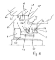
- the mechanical seal after Fig. 9 has the damping member 68, which has in contrast to the damping member 24 as a spring portion no ribs and depressions, but cylindrical spring portions.
- the embodiment is the same as the embodiment according to except for the design of the damping member Fig. 2 ,
- the damping part 68 is designed as a ring cup, which has a radially outer cylinder jacket 69 and a radially inner cylinder jacket 70, which merge into one another through a radial bottom 71.
- the two cylinder jackets 69, 70 are coaxial with each other and to be sealed shaft 5.
- the outer cylinder jacket 69 is axially longer than the inner cylinder jacket 70.
- the outer cylinder jacket 69 projects into the housing 1 and is applied to the inner wall of the housing shell 10 under radial prestress.
- the shorter cylinder jacket 70 rests on the cylindrical portion 41 of the secondary seal 6 and loads it in the radial direction.
- the cylinder jacket 70 has a small axial distance from the cylinder portion 45 of the spring plate 9.
- the lying in a radial plane Floor 71 of the damping member 68 is equal to the shoulder surface 58 of the sliding ring. 3
- the cylinder jacket 69 is radially resilient so that it can absorb corresponding radial movements of the seal ring 3 by elastic deformation. The noise is thereby avoided. As with the damping member 24, the intended micro-friction contributes to optimal damping.
- the mechanical seal after Fig. 10 essentially corresponds to the embodiment according to Fig. 9 ,
- the damping member 68 has the cylindrical outer jacket 69, which rests in the manner described under radial bias on the inside of the shell 10 of the housing 1.
- the radially inner cylinder jacket 70 does not extend in the same direction as the outer cylinder jacket 69, but in the direction of the mating ring 4.
- the inner cylinder jacket 70 is located on the outer circumferential surface 19 of the seal ring 3 in the area outside the recess 40th on.
- the cylinder jacket 69 is sufficiently resilient due to its axial length, so that it can yield radially correspondingly.
- the mechanical seal is the same way as the embodiment according to the rest Fig. 9 ,
- Fig. 11 shows a damping member 68, the bottom 71 is formed part-circular curved in axial section.
- the radially inner cylinder jacket 70 rests on the cylinder portion 45 of the spring plate 9 under radial bias.
- the outer cylinder jacket 69 according to the Fig. 12 . 12a . 12b and 13 be profiled wavy over its circumference, so that the cylinder jacket rests only with the rib-like elevations on the housing shell 10.
- the mechanical seal according to the invention Fig. 14 In its construction substantially corresponds to the embodiment according to Fig. 1 , The difference lies in the design and arrangement of the damping part 24. It is supported axially on the cylindrical part 21 of the spring plate 9, which sits on the secondary seal 6 and on which the compression spring 7 engages. The damping member 24 is also supported on the radially outwardly projecting edge 10 'of the housing 1.
- the damping member 24 has the in the FIGS. 15 and 16 illustrated training. It is designed as a closed ring and has a ring member 75 which is formed as a flat annular disc. On the inside 76 of the ring member 75 distributed over the circumference spring tongues 77 are provided, which are advantageously the same design and advantageously have the same distance from each other.
- the spring tongues project obliquely inwards and are elastically deformed in the installation position of the damping part 24.
- Fig. 14 are the spring tongues 77 under elastic deformation on the cylindrical part 21 of the spring plate 9 at.
- the damping member 24 is located on the radially outwardly directed edge 10 'of the housing 1 at.
- the spring tongues 77 project slightly in the direction of the bottom 8 of the housing 1 via the annular web 9 'of the spring plate 9.
- the spring tongues 7 also have a radial distance from the inner wall of the outer shell 10 of the housing first
- the damping member 24 is again installed so that the spring tongues 77 generate the micro-friction for noise damping in the circumferential direction.
- This circumferential direction is, as already with the damping parts 24 according to the Fig. 12 . 12a . 12b and 13 , the main direction for the generation of micro friction, while the axial direction of the mechanical seal for the vibration damping plays no role.
- the mechanical seal according to the invention Fig. 17 is the same design as the mechanical seal after Fig. 14 , Only the damping member 24 has a different design and installation position.
- the spring tongues 77 of the damping member 24 are provided on the outside of the disc-shaped ring member 75.
- the spring tongues 77 are directed obliquely outwards. They lie in the installed position under elastic deformation on the inside of the outer shell 10 of the housing 1 ( Fig. 17 ).
- the spring tongues 77 extend from the ring part 75 slightly beyond the radially outwardly directed free edge 10 'of the housing 1.
- the spring tongues 77 are at a radial distance from the spring plate 9.
- the ring member 75 of the damping member 24 abuts the radial annular web 9 'of the spring plate 9 under the force of the compression spring 7.
- the ring member 75 may extend to the radially inner cylinder portion 20 of the spring plate 9.
- the elastic spring tongues 77 are under elastic bias on the housing 1, while lying in a radial plane ring member 75 rests against the radial annular web 9 'of the spring plate 9.
- Fig. 20 shows a mechanical seal, which is formed substantially the same as the mechanical seal according to the Fig. 14 or 17 , Only the damping part 24 has a different design.
- the damping member 24 has two disc-shaped ring members 78, 79 which are each in a radial plane of the mechanical seal and pass through a serving as a spring part cone member 80 into each other.
- the radially outer ring member 78 abuts the free edge 10 'of the housing 1.
- the radially inner ring member 79 abuts the radial annular web 9 'of the spring plate 9.
- the ring member 79 is pressed by the compression spring 7 axially against the radial annular web 9 'of the spring plate 9.
- the micro friction occurs between the radially extending ring members 78, 79 of the damping member 24 and the radial Edge 10 'of the housing 1 and the radial annular web 9' of the spring plate.
- the damping part 24 has cylindrical ring parts 78 ', 79'.
- the damping part 24 is arranged so that the annular part 78 'rests on the outside of the cylinder part 21 of the spring plate 9 and the ring part 79' on the inside of the outer shell 10 of the housing 1.
- the cylindrical ring members 78 'and 79' are interconnected by the cone member 80.
- the mechanical seal is the same design as the mechanical seal according to Fig. 20 ,
- the ring parts 69, 70; 77, 78, 79; 78 ', 79' can be segmented.
- the damping member 24 is formed integrally with the spring plate 9.
- the mechanical seal has the same structure as the mechanical seal Fig. 1 ,
- the radially outwardly directed annular edge of the spring plate 9 forms the damping part 24 which is surrounded by the retaining element 48. It is according to the embodiment according to Fig. 4 formed and is attached with its flange 51 at the free edge 10 'of the housing 1.
- a spring member 81 is supported, which extends between the flange 49 and the damping member 24 and rests under axial bias on these two parts.
- the spring member 81 may be, for example, a corrugated spring.
Landscapes
- Engineering & Computer Science (AREA)
- General Engineering & Computer Science (AREA)
- Mechanical Engineering (AREA)
- Mechanical Sealing (AREA)
- Gasket Seals (AREA)
- Sealing With Elastic Sealing Lips (AREA)
- Sealing Devices (AREA)
- Fluid-Damping Devices (AREA)
- Fuel-Injection Apparatus (AREA)
Claims (4)
- Garniture mécanique d'étanchéité pour un arbre (5), comprenant au moins un support de maintien (2) pour au moins l'un des éléments d'étanchéité (3, 4) formés par un anneau d'étanchéité et un anneau conjugué, qui s'appuient de manière étanche l'un contre l'autre sous l'action d'une force axiale, la garniture comprenant également une partie d'amortissement (24), qui présente au moins une pièce de tôle ayant subi un formage et pourvue d'au moins une partie de ressort (77) déformable de manière élastique, qui s'appuie sous précontrainte pour produire une micro-friction entre la partie d'amortissement (24) et la zone d'appui,
caractérisée en ce que le support de maintien (2) loge l'anneau conjugué (4), qui peut être relié en rotation, de manière fixe, avec l'arbre (5) par l'intermédiaire du support de maintien (2), en ce que l'anneau conjugué (4) est placé sur une manchette (30) de forme annulaire servant de joint d'étanchéité, qui se situe entre un tronçon cylindrique (28) du support de maintien (2) et une surface intérieure cylindrique (27) de l'anneau conjugué (4) et maintient l'anneau conjugué (4) dans le support de maintien (2), en ce que la partie d'amortissement (24) s'appuie contre l'anneau de glissement d'étanchéité (3) avec interposition d'une coupelle de ressort (9, 9a) et d'un joint d'étanchéité secondaire (6), et en ce que la partie de ressort (77) est une languette qui fait saillie de manière inclinée d'une partie annulaire (75) de la partie d'amortissement (24), et qui, en position implantée, est déformée élastiquement et s'étend dans la direction axiale de la garniture mécanique d'étanchéité. - Garniture mécanique d'étanchéité selon la revendication 1,
caractérisée en ce que la partie de ressort (77), s'appuie contre le carter (1), de préférence sous précontrainte radiale ou axiale. - Garniture mécanique d'étanchéité selon la revendication 1,
caractérisée en ce que la partie de ressort (77) s'appuie contre une coupelle de ressort (9). - Garniture mécanique d'étanchéité selon l'une des revendications 1 à 3,
caractérisée en ce qu'au moins la partie de ressort (77) fait saillie partiellement hors du carter (1).
Applications Claiming Priority (1)
| Application Number | Priority Date | Filing Date | Title |
|---|---|---|---|
| DE102009049093A DE102009049093A1 (de) | 2009-10-01 | 2009-10-01 | Gleitringdichtung |
Publications (2)
| Publication Number | Publication Date |
|---|---|
| EP2306052A1 EP2306052A1 (fr) | 2011-04-06 |
| EP2306052B1 true EP2306052B1 (fr) | 2014-04-30 |
Family
ID=43415227
Family Applications (1)
| Application Number | Title | Priority Date | Filing Date |
|---|---|---|---|
| EP10008648.7A Active EP2306052B1 (fr) | 2009-10-01 | 2010-08-19 | Joint mécanique |
Country Status (8)
| Country | Link |
|---|---|
| US (1) | US9010764B2 (fr) |
| EP (1) | EP2306052B1 (fr) |
| JP (1) | JP5711926B2 (fr) |
| CN (1) | CN102032347B (fr) |
| BR (1) | BRPI1003806B1 (fr) |
| CA (1) | CA2714981C (fr) |
| DE (1) | DE102009049093A1 (fr) |
| MX (1) | MX340195B (fr) |
Families Citing this family (12)
| Publication number | Priority date | Publication date | Assignee | Title |
|---|---|---|---|---|
| WO2014173495A2 (fr) | 2013-04-22 | 2014-10-30 | Carl Freudenberg Kg | Joint d'étanchéité à bague de glissement |
| EP3196514B1 (fr) * | 2014-07-24 | 2021-01-27 | Eagle Industry Co., Ltd. | Pompe avec joint d'étanchéité mécanique |
| CN106605089B (zh) * | 2014-09-24 | 2018-07-06 | 伊格尔工业股份有限公司 | 机械密封件 |
| WO2016050534A1 (fr) * | 2014-09-30 | 2016-04-07 | Siemens Aktiengesellschaft | Machine electrique à refroidissement par liquide |
| EP3220020B1 (fr) * | 2014-11-11 | 2020-01-08 | Nok Corporation | Dispositif de joint d'étanchéité |
| JP6881882B2 (ja) | 2016-09-14 | 2021-06-02 | イーグル工業株式会社 | メカニカルシール |
| US10975967B2 (en) | 2016-09-16 | 2021-04-13 | Flowserve Management Company | Radially and axially self-aligning split seal ring |
| EP3568620B1 (fr) * | 2017-01-12 | 2021-05-05 | Flowserve Management Company | Mécanisme d'assemblage de bagues d'étanchéité fendues |
| CN107143615A (zh) * | 2017-06-29 | 2017-09-08 | 湖北威能达驱动技术系统有限公司 | 一种弹片预应力密封组合 |
| DE102017219190B4 (de) * | 2017-10-26 | 2022-12-29 | Eagleburgmann Germany Gmbh & Co. Kg | Gasgeschmierte Gleitringdichtung mit verbessertem Verschmutzungsschutz |
| EP3757432B1 (fr) * | 2018-02-21 | 2023-10-18 | Eagle Industry Co., Ltd. | Joint mécanique |
| FR3095847B1 (fr) * | 2019-05-06 | 2021-08-13 | Cyclam | garniture d’étanchéité COMPACTE pour assurer l’étanchéité entre un arbre rotatif et un corps stationnaire d’une machine |
Family Cites Families (22)
| Publication number | Priority date | Publication date | Assignee | Title |
|---|---|---|---|---|
| DE19860250C1 (de) | 1998-12-24 | 2000-11-02 | Daimler Chrysler Ag | Zahnräderwechselgetriebe mit zwei im Kraftfluß parallel zueinander angeordneten Teilgetrieben |
| US3515394A (en) * | 1964-06-05 | 1970-06-02 | Sealol | Vibration damping means for resilient convoluted members |
| JPS5465249A (en) | 1977-11-01 | 1979-05-25 | Akira Washida | Mechanical seal |
| JPS57153854A (en) | 1981-03-12 | 1982-09-22 | Hitachi Shipbuilding Eng Co | Hanger for vessel of powdered and granular body |
| JPS6145405Y2 (fr) * | 1981-03-20 | 1986-12-20 | ||
| JPS60194668A (ja) | 1984-03-16 | 1985-10-03 | Hitachi Ltd | 画像読取センサ |
| JPS60194668U (ja) * | 1984-06-05 | 1985-12-25 | イーグル工業株式会社 | メカニカルシ−ル用緩衝ゴム |
| JPH0229313Y2 (fr) * | 1985-11-06 | 1990-08-07 | ||
| US6311983B1 (en) * | 1989-09-26 | 2001-11-06 | The Boeing Company | Combination static lift-off face contact seal and floating ring shaft seal |
| JPH09292034A (ja) | 1996-04-25 | 1997-11-11 | Mitsubishi Heavy Ind Ltd | メカニカルシール |
| US5873574A (en) * | 1996-07-18 | 1999-02-23 | John Crane Sealol Inc. | Bellows seal with reverse pressure capability |
| DE19739398A1 (de) * | 1997-09-09 | 1999-03-11 | Kaco Gmbh Co | Dichtung |
| JP2000074226A (ja) * | 1998-08-27 | 2000-03-14 | Eagle Ind Co Ltd | メカニカルシール |
| FR2787851B1 (fr) * | 1998-12-24 | 2001-03-23 | Snecma | Amortisseur de joint dynamique |
| US6398223B1 (en) * | 2000-08-21 | 2002-06-04 | John Crane Inc. | Mechanical face seal |
| JP2002195420A (ja) * | 2001-12-26 | 2002-07-10 | Eagle Ind Co Ltd | 回転環の変形制御方法 |
| DE20206927U1 (de) | 2002-05-01 | 2003-09-04 | Dassler Puma Sportschuh | Dämpfungselement für einen Schuh |
| JP3966474B2 (ja) * | 2003-10-02 | 2007-08-29 | 日産自動車株式会社 | シールリング及びシール装置 |
| SE527765C2 (sv) | 2004-10-21 | 2006-05-30 | Roplan Dev Ct Ab | Stödring och axelgenomföring |
| DE102005036338A1 (de) * | 2005-07-29 | 2007-02-15 | Wilo Ag | Gleitringdichtung |
| US8128097B2 (en) * | 2006-06-08 | 2012-03-06 | Eagle Industry Co., Ltd. | Mechanical seal |
| JP4793151B2 (ja) * | 2006-07-18 | 2011-10-12 | いすゞ自動車株式会社 | メカニカルシール装置及びウォーターポンプ |
-
2009
- 2009-10-01 DE DE102009049093A patent/DE102009049093A1/de not_active Withdrawn
-
2010
- 2010-08-19 EP EP10008648.7A patent/EP2306052B1/fr active Active
- 2010-09-20 CA CA2714981A patent/CA2714981C/fr not_active Expired - Fee Related
- 2010-09-25 US US12/890,604 patent/US9010764B2/en not_active Expired - Fee Related
- 2010-09-28 CN CN201010297809.7A patent/CN102032347B/zh active Active
- 2010-09-30 JP JP2010221790A patent/JP5711926B2/ja active Active
- 2010-09-30 MX MX2010010739A patent/MX340195B/es active IP Right Grant
- 2010-10-01 BR BRPI1003806-0A patent/BRPI1003806B1/pt not_active IP Right Cessation
Also Published As
| Publication number | Publication date |
|---|---|
| US20110079961A1 (en) | 2011-04-07 |
| BRPI1003806B1 (pt) | 2020-02-11 |
| EP2306052A1 (fr) | 2011-04-06 |
| CA2714981C (fr) | 2017-04-04 |
| BRPI1003806A2 (pt) | 2013-02-13 |
| CN102032347A (zh) | 2011-04-27 |
| DE102009049093A1 (de) | 2011-04-07 |
| US9010764B2 (en) | 2015-04-21 |
| MX340195B (es) | 2016-06-30 |
| JP5711926B2 (ja) | 2015-05-07 |
| MX2010010739A (es) | 2011-05-04 |
| CN102032347B (zh) | 2015-07-08 |
| JP2011075102A (ja) | 2011-04-14 |
| CA2714981A1 (fr) | 2011-04-01 |
Similar Documents
| Publication | Publication Date | Title |
|---|---|---|
| EP2306052B1 (fr) | Joint mécanique | |
| DE102007050349B4 (de) | Dichtungsanordnung für den Hochdruckbereich | |
| EP0557579B1 (fr) | Dispositif d'étanchéité | |
| EP3596363B1 (fr) | Ensemble d'étanchéité | |
| EP1585906B1 (fr) | Ensemble pour bloquer un circlips | |
| DE3219156C2 (fr) | ||
| DE102017111668B4 (de) | Lagerbuchse | |
| EP2817539B1 (fr) | Joint radial d'arbre | |
| EP0493731B1 (fr) | Flexibloc pour articulation | |
| EP2199639A2 (fr) | Frein à disque pour un véhicule utilitaire | |
| DE102012222269A1 (de) | Reibungskupplung | |
| EP2618032B1 (fr) | Joint d'étanchéité d'arbre, notamment joint d'arbre radial | |
| EP1691104B1 (fr) | Support élastique | |
| DE112014001037B4 (de) | Reibungskupplung | |
| DE10113442C2 (de) | Lageranordnung für ein Wellenlager | |
| DE4225556A1 (de) | Zwischen radial nach innen weisenden Vorsprüngen einer Zylinderfläche abgestützte Stangenführung | |
| DE102007053724A1 (de) | Kupplungsvorrichtung | |
| DE10005547A1 (de) | Schwingungsdämpfungseinrichtung | |
| EP3277977B1 (fr) | Amortisseur axial | |
| EP1841981A1 (fr) | Frein a disque | |
| WO2020126071A1 (fr) | Ensemble d'étanchéité à bagues de glissement | |
| EP1747384B1 (fr) | Ensemble palier constitue d'un palier et d'un support de palier | |
| DE102012220839A1 (de) | Rampensystem für eine Nachstelleinrichtung einer Reibungskupplung | |
| EP2875251A1 (fr) | Dispositif à butée de débrayage | |
| EP3417192B1 (fr) | Joint d'arbre |
Legal Events
| Date | Code | Title | Description |
|---|---|---|---|
| PUAI | Public reference made under article 153(3) epc to a published international application that has entered the european phase |
Free format text: ORIGINAL CODE: 0009012 |
|
| AK | Designated contracting states |
Kind code of ref document: A1 Designated state(s): AL AT BE BG CH CY CZ DE DK EE ES FI FR GB GR HR HU IE IS IT LI LT LU LV MC MK MT NL NO PL PT RO SE SI SK SM TR |
|
| AX | Request for extension of the european patent |
Extension state: BA ME RS |
|
| 17P | Request for examination filed |
Effective date: 20111006 |
|
| 17Q | First examination report despatched |
Effective date: 20120426 |
|
| GRAP | Despatch of communication of intention to grant a patent |
Free format text: ORIGINAL CODE: EPIDOSNIGR1 |
|
| INTG | Intention to grant announced |
Effective date: 20131121 |
|
| GRAS | Grant fee paid |
Free format text: ORIGINAL CODE: EPIDOSNIGR3 |
|
| GRAA | (expected) grant |
Free format text: ORIGINAL CODE: 0009210 |
|
| AK | Designated contracting states |
Kind code of ref document: B1 Designated state(s): AL AT BE BG CH CY CZ DE DK EE ES FI FR GB GR HR HU IE IS IT LI LT LU LV MC MK MT NL NO PL PT RO SE SI SK SM TR |
|
| REG | Reference to a national code |
Ref country code: GB Ref legal event code: FG4D Free format text: NOT ENGLISH Ref country code: CH Ref legal event code: EP |
|
| REG | Reference to a national code |
Ref country code: AT Ref legal event code: REF Ref document number: 665367 Country of ref document: AT Kind code of ref document: T Effective date: 20140515 |
|
| REG | Reference to a national code |
Ref country code: IE Ref legal event code: FG4D Free format text: LANGUAGE OF EP DOCUMENT: GERMAN |
|
| REG | Reference to a national code |
Ref country code: DE Ref legal event code: R096 Ref document number: 502010006774 Country of ref document: DE Effective date: 20140612 |
|
| REG | Reference to a national code |
Ref country code: LT Ref legal event code: MG4D |
|
| REG | Reference to a national code |
Ref country code: NL Ref legal event code: VDEP Effective date: 20140430 |
|
| PG25 | Lapsed in a contracting state [announced via postgrant information from national office to epo] |
Ref country code: NL Free format text: LAPSE BECAUSE OF FAILURE TO SUBMIT A TRANSLATION OF THE DESCRIPTION OR TO PAY THE FEE WITHIN THE PRESCRIBED TIME-LIMIT Effective date: 20140430 Ref country code: IS Free format text: LAPSE BECAUSE OF FAILURE TO SUBMIT A TRANSLATION OF THE DESCRIPTION OR TO PAY THE FEE WITHIN THE PRESCRIBED TIME-LIMIT Effective date: 20140830 Ref country code: CY Free format text: LAPSE BECAUSE OF FAILURE TO SUBMIT A TRANSLATION OF THE DESCRIPTION OR TO PAY THE FEE WITHIN THE PRESCRIBED TIME-LIMIT Effective date: 20140430 Ref country code: BG Free format text: LAPSE BECAUSE OF FAILURE TO SUBMIT A TRANSLATION OF THE DESCRIPTION OR TO PAY THE FEE WITHIN THE PRESCRIBED TIME-LIMIT Effective date: 20140730 Ref country code: FI Free format text: LAPSE BECAUSE OF FAILURE TO SUBMIT A TRANSLATION OF THE DESCRIPTION OR TO PAY THE FEE WITHIN THE PRESCRIBED TIME-LIMIT Effective date: 20140430 Ref country code: LT Free format text: LAPSE BECAUSE OF FAILURE TO SUBMIT A TRANSLATION OF THE DESCRIPTION OR TO PAY THE FEE WITHIN THE PRESCRIBED TIME-LIMIT Effective date: 20140430 Ref country code: NO Free format text: LAPSE BECAUSE OF FAILURE TO SUBMIT A TRANSLATION OF THE DESCRIPTION OR TO PAY THE FEE WITHIN THE PRESCRIBED TIME-LIMIT Effective date: 20140730 Ref country code: GR Free format text: LAPSE BECAUSE OF FAILURE TO SUBMIT A TRANSLATION OF THE DESCRIPTION OR TO PAY THE FEE WITHIN THE PRESCRIBED TIME-LIMIT Effective date: 20140731 |
|
| PG25 | Lapsed in a contracting state [announced via postgrant information from national office to epo] |
Ref country code: PL Free format text: LAPSE BECAUSE OF FAILURE TO SUBMIT A TRANSLATION OF THE DESCRIPTION OR TO PAY THE FEE WITHIN THE PRESCRIBED TIME-LIMIT Effective date: 20140430 Ref country code: LV Free format text: LAPSE BECAUSE OF FAILURE TO SUBMIT A TRANSLATION OF THE DESCRIPTION OR TO PAY THE FEE WITHIN THE PRESCRIBED TIME-LIMIT Effective date: 20140430 Ref country code: SE Free format text: LAPSE BECAUSE OF FAILURE TO SUBMIT A TRANSLATION OF THE DESCRIPTION OR TO PAY THE FEE WITHIN THE PRESCRIBED TIME-LIMIT Effective date: 20140430 Ref country code: HR Free format text: LAPSE BECAUSE OF FAILURE TO SUBMIT A TRANSLATION OF THE DESCRIPTION OR TO PAY THE FEE WITHIN THE PRESCRIBED TIME-LIMIT Effective date: 20140430 Ref country code: ES Free format text: LAPSE BECAUSE OF FAILURE TO SUBMIT A TRANSLATION OF THE DESCRIPTION OR TO PAY THE FEE WITHIN THE PRESCRIBED TIME-LIMIT Effective date: 20140430 |
|
| PG25 | Lapsed in a contracting state [announced via postgrant information from national office to epo] |
Ref country code: PT Free format text: LAPSE BECAUSE OF FAILURE TO SUBMIT A TRANSLATION OF THE DESCRIPTION OR TO PAY THE FEE WITHIN THE PRESCRIBED TIME-LIMIT Effective date: 20140901 |
|
| PG25 | Lapsed in a contracting state [announced via postgrant information from national office to epo] |
Ref country code: RO Free format text: LAPSE BECAUSE OF FAILURE TO SUBMIT A TRANSLATION OF THE DESCRIPTION OR TO PAY THE FEE WITHIN THE PRESCRIBED TIME-LIMIT Effective date: 20140430 Ref country code: EE Free format text: LAPSE BECAUSE OF FAILURE TO SUBMIT A TRANSLATION OF THE DESCRIPTION OR TO PAY THE FEE WITHIN THE PRESCRIBED TIME-LIMIT Effective date: 20140430 Ref country code: SK Free format text: LAPSE BECAUSE OF FAILURE TO SUBMIT A TRANSLATION OF THE DESCRIPTION OR TO PAY THE FEE WITHIN THE PRESCRIBED TIME-LIMIT Effective date: 20140430 Ref country code: DK Free format text: LAPSE BECAUSE OF FAILURE TO SUBMIT A TRANSLATION OF THE DESCRIPTION OR TO PAY THE FEE WITHIN THE PRESCRIBED TIME-LIMIT Effective date: 20140430 Ref country code: CZ Free format text: LAPSE BECAUSE OF FAILURE TO SUBMIT A TRANSLATION OF THE DESCRIPTION OR TO PAY THE FEE WITHIN THE PRESCRIBED TIME-LIMIT Effective date: 20140430 |
|
| REG | Reference to a national code |
Ref country code: DE Ref legal event code: R097 Ref document number: 502010006774 Country of ref document: DE |
|
| PLBE | No opposition filed within time limit |
Free format text: ORIGINAL CODE: 0009261 |
|
| STAA | Information on the status of an ep patent application or granted ep patent |
Free format text: STATUS: NO OPPOSITION FILED WITHIN TIME LIMIT |
|
| PG25 | Lapsed in a contracting state [announced via postgrant information from national office to epo] |
Ref country code: LU Free format text: LAPSE BECAUSE OF FAILURE TO SUBMIT A TRANSLATION OF THE DESCRIPTION OR TO PAY THE FEE WITHIN THE PRESCRIBED TIME-LIMIT Effective date: 20140819 Ref country code: MC Free format text: LAPSE BECAUSE OF FAILURE TO SUBMIT A TRANSLATION OF THE DESCRIPTION OR TO PAY THE FEE WITHIN THE PRESCRIBED TIME-LIMIT Effective date: 20140430 |
|
| REG | Reference to a national code |
Ref country code: CH Ref legal event code: PL |
|
| 26N | No opposition filed |
Effective date: 20150202 |
|
| PG25 | Lapsed in a contracting state [announced via postgrant information from national office to epo] |
Ref country code: CH Free format text: LAPSE BECAUSE OF NON-PAYMENT OF DUE FEES Effective date: 20140831 Ref country code: LI Free format text: LAPSE BECAUSE OF NON-PAYMENT OF DUE FEES Effective date: 20140831 Ref country code: BE Free format text: LAPSE BECAUSE OF NON-PAYMENT OF DUE FEES Effective date: 20140831 |
|
| REG | Reference to a national code |
Ref country code: DE Ref legal event code: R097 Ref document number: 502010006774 Country of ref document: DE Effective date: 20150202 |
|
| REG | Reference to a national code |
Ref country code: IE Ref legal event code: MM4A |
|
| PG25 | Lapsed in a contracting state [announced via postgrant information from national office to epo] |
Ref country code: SI Free format text: LAPSE BECAUSE OF FAILURE TO SUBMIT A TRANSLATION OF THE DESCRIPTION OR TO PAY THE FEE WITHIN THE PRESCRIBED TIME-LIMIT Effective date: 20140430 |
|
| PG25 | Lapsed in a contracting state [announced via postgrant information from national office to epo] |
Ref country code: IE Free format text: LAPSE BECAUSE OF NON-PAYMENT OF DUE FEES Effective date: 20140819 |
|
| PG25 | Lapsed in a contracting state [announced via postgrant information from national office to epo] |
Ref country code: SM Free format text: LAPSE BECAUSE OF FAILURE TO SUBMIT A TRANSLATION OF THE DESCRIPTION OR TO PAY THE FEE WITHIN THE PRESCRIBED TIME-LIMIT Effective date: 20140430 |
|
| PG25 | Lapsed in a contracting state [announced via postgrant information from national office to epo] |
Ref country code: MT Free format text: LAPSE BECAUSE OF FAILURE TO SUBMIT A TRANSLATION OF THE DESCRIPTION OR TO PAY THE FEE WITHIN THE PRESCRIBED TIME-LIMIT Effective date: 20140430 |
|
| PG25 | Lapsed in a contracting state [announced via postgrant information from national office to epo] |
Ref country code: HU Free format text: LAPSE BECAUSE OF FAILURE TO SUBMIT A TRANSLATION OF THE DESCRIPTION OR TO PAY THE FEE WITHIN THE PRESCRIBED TIME-LIMIT; INVALID AB INITIO Effective date: 20100819 Ref country code: TR Free format text: LAPSE BECAUSE OF FAILURE TO SUBMIT A TRANSLATION OF THE DESCRIPTION OR TO PAY THE FEE WITHIN THE PRESCRIBED TIME-LIMIT Effective date: 20140430 |
|
| REG | Reference to a national code |
Ref country code: FR Ref legal event code: PLFP Year of fee payment: 7 |
|
| REG | Reference to a national code |
Ref country code: AT Ref legal event code: MM01 Ref document number: 665367 Country of ref document: AT Kind code of ref document: T Effective date: 20150819 |
|
| PG25 | Lapsed in a contracting state [announced via postgrant information from national office to epo] |
Ref country code: AT Free format text: LAPSE BECAUSE OF NON-PAYMENT OF DUE FEES Effective date: 20150819 |
|
| REG | Reference to a national code |
Ref country code: FR Ref legal event code: PLFP Year of fee payment: 8 |
|
| PG25 | Lapsed in a contracting state [announced via postgrant information from national office to epo] |
Ref country code: MK Free format text: LAPSE BECAUSE OF FAILURE TO SUBMIT A TRANSLATION OF THE DESCRIPTION OR TO PAY THE FEE WITHIN THE PRESCRIBED TIME-LIMIT Effective date: 20140430 |
|
| REG | Reference to a national code |
Ref country code: FR Ref legal event code: PLFP Year of fee payment: 9 |
|
| PG25 | Lapsed in a contracting state [announced via postgrant information from national office to epo] |
Ref country code: AL Free format text: LAPSE BECAUSE OF FAILURE TO SUBMIT A TRANSLATION OF THE DESCRIPTION OR TO PAY THE FEE WITHIN THE PRESCRIBED TIME-LIMIT Effective date: 20140430 |
|
| REG | Reference to a national code |
Ref country code: DE Ref legal event code: R081 Ref document number: 502010006774 Country of ref document: DE Owner name: KACO GMBH + CO. KG, DE Free format text: FORMER OWNER: KACO GMBH + CO. KG, 74072 HEILBRONN, DE Ref country code: DE Ref legal event code: R082 Ref document number: 502010006774 Country of ref document: DE Representative=s name: JACKISCH-KOHL UND KOHL, DE |
|
| PGFP | Annual fee paid to national office [announced via postgrant information from national office to epo] |
Ref country code: GB Payment date: 20200813 Year of fee payment: 11 |
|
| PGFP | Annual fee paid to national office [announced via postgrant information from national office to epo] |
Ref country code: IT Payment date: 20200805 Year of fee payment: 11 |
|
| GBPC | Gb: european patent ceased through non-payment of renewal fee |
Effective date: 20210819 |
|
| PG25 | Lapsed in a contracting state [announced via postgrant information from national office to epo] |
Ref country code: IT Free format text: LAPSE BECAUSE OF NON-PAYMENT OF DUE FEES Effective date: 20210819 Ref country code: GB Free format text: LAPSE BECAUSE OF NON-PAYMENT OF DUE FEES Effective date: 20210819 |
|
| PGFP | Annual fee paid to national office [announced via postgrant information from national office to epo] |
Ref country code: FR Payment date: 20230620 Year of fee payment: 14 |
|
| PGFP | Annual fee paid to national office [announced via postgrant information from national office to epo] |
Ref country code: DE Payment date: 20230821 Year of fee payment: 14 |