EP2302769A1 - Electric motor - Google Patents
Electric motor Download PDFInfo
- Publication number
- EP2302769A1 EP2302769A1 EP09773477A EP09773477A EP2302769A1 EP 2302769 A1 EP2302769 A1 EP 2302769A1 EP 09773477 A EP09773477 A EP 09773477A EP 09773477 A EP09773477 A EP 09773477A EP 2302769 A1 EP2302769 A1 EP 2302769A1
- Authority
- EP
- European Patent Office
- Prior art keywords
- wire
- wires
- coil winding
- winding wire
- winding
- Prior art date
- Legal status (The legal status is an assumption and is not a legal conclusion. Google has not performed a legal analysis and makes no representation as to the accuracy of the status listed.)
- Withdrawn
Links
Images





















Classifications
-
- H—ELECTRICITY
- H02—GENERATION; CONVERSION OR DISTRIBUTION OF ELECTRIC POWER
- H02K—DYNAMO-ELECTRIC MACHINES
- H02K23/00—DC commutator motors or generators having mechanical commutator; Universal AC/DC commutator motors
- H02K23/02—DC commutator motors or generators having mechanical commutator; Universal AC/DC commutator motors characterised by arrangement for exciting
- H02K23/20—DC commutator motors or generators having mechanical commutator; Universal AC/DC commutator motors characterised by arrangement for exciting having additional brushes spaced intermediately of the main brushes on the commutator, e.g. cross-field machines, metadynes, amplidynes or other armature-reaction excited machines
-
- H—ELECTRICITY
- H02—GENERATION; CONVERSION OR DISTRIBUTION OF ELECTRIC POWER
- H02K—DYNAMO-ELECTRIC MACHINES
- H02K23/00—DC commutator motors or generators having mechanical commutator; Universal AC/DC commutator motors
- H02K23/26—DC commutator motors or generators having mechanical commutator; Universal AC/DC commutator motors characterised by the armature windings
- H02K23/30—DC commutator motors or generators having mechanical commutator; Universal AC/DC commutator motors characterised by the armature windings having lap or loop windings
-
- Y—GENERAL TAGGING OF NEW TECHNOLOGICAL DEVELOPMENTS; GENERAL TAGGING OF CROSS-SECTIONAL TECHNOLOGIES SPANNING OVER SEVERAL SECTIONS OF THE IPC; TECHNICAL SUBJECTS COVERED BY FORMER USPC CROSS-REFERENCE ART COLLECTIONS [XRACs] AND DIGESTS
- Y02—TECHNOLOGIES OR APPLICATIONS FOR MITIGATION OR ADAPTATION AGAINST CLIMATE CHANGE
- Y02T—CLIMATE CHANGE MITIGATION TECHNOLOGIES RELATED TO TRANSPORTATION
- Y02T10/00—Road transport of goods or passengers
- Y02T10/60—Other road transportation technologies with climate change mitigation effect
- Y02T10/64—Electric machine technologies in electromobility
Definitions
- the present invention relates to an electric motor which is mounted to automobiles or the like, and particularly, to an electric motor capable of changing the rotational speed of an armature provided in the electric motor.
- Priority is claimed on Japanese Patent Application Nos. 2008-170738 , 2008-170739 , and 2008-170740 filed on June 30, 2008 , Japanese Patent Application No. 2009-039598 filed on February 23, 2009 , and Japanese Patent Application No. 2009-068640 filed on March 19, 2009 , the contents of which are incorporated herein by reference.
- This electric motor has a cylindrical yoke, a plurality of permanent magnets arranged on the inner circumferential surface of this yoke, and an armature arranged inside these permanent magnets and rotatable with respect to the yoke.
- This armature has a rotary shaft, and an armature core which is fixed onto this shaft and has a plurality of radially formed teeth, and a coil wound around the teeth.
- the coil has a plurality of winding wires wound around the teeth through slots formed between the teeth. The respective winding wires are connected to a plurality of segments of the commutator fixed to the rotary shaft.
- the commutator has a plurality of segments which is formed from metal pieces, is insulated from each other and disposed in a columnar shape. A winding starting end and a winding finishing end of the winding wire are connected to each of the segments. Additionally, a plurality of brushes is connected to the segments of the commutator so as to be capable of making sliding contact therewith, and an electric current is supplied to the coil via these brushes. Also, a magnetic field is formed in the teeth of the armature core due to an electric current which flows through the coil, and the armature is rotated with the rotary shaft by a magnetic attractive force or repulsive force which is generated between the teeth and the permanent magnets fixed onto the yoke.
- this electric motor there is a motor including a total of three brushes, a brush for low speed and a brush for high speed which are selectively connected to a positive terminal of a power source and a common brush connected to a negative terminal of the power source.
- a motor including a total of three brushes, a brush for low speed and a brush for high speed which are selectively connected to a positive terminal of a power source and a common brush connected to a negative terminal of the power source.
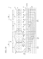
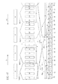
- FIG. 17 is a developed view of an electric motor 80 with four poles, sixteen slots, and sixteen segments, having four permanent magnets (two pole pairs), sixteen teeth (slots), and sixteen segments, which is disclosed in PTL 1.
- the permanent magnets 81 N poles and S poles are arranged alternately.
- the slots 83 are gaps between the teeth 82 adjacent to each other.
- No. 1 to No. 16 are given to the respective teeth 82 and the respective segments 84.
- a winding wire 87 and a winding wire 88 which is arranged at a position which is point symmetric with respect to the winding wire 87, are substantially simultaneously wound around the teeth 82 by a double flyer.
- the winding wire 87 is split into two coil winding wires 93A and 93B, and is wound around the teeth 82 with different numbers. That is, the winding wire 87 connected to a No. 2 segment 84e passes through a slot 83e between a No. 16 tooth 82 and a No. 1 tooth 82, passes through a slot 83f between a No. 3 tooth 82 and a No. 4 tooth 82, and is wound in a forward direction around No. 1, No. 2, and No. 3 teeth 82 n times (n is a natural number), whereby a coil winding wire 93A is formed.
- the winding wire 87 passes through a slot 83g between a No. 7 tooth 82 and a No. 8 tooth 82, passes through a slot 83b between a No. 4 tooth 82 and a No. 5 tooth 82, is wound in an opposite direction around No. 5, No. 6, and No. 7 teeth 82 n times, and is connected to a No. 3 segment 84a, whereby a coil winding wire 93B is formed.
- the slot 83g exists at a position deviated in a circumferential direction from the slot 83f by a mechanical angle of 90°
- the slot 83b exists at a position deviated in a circumferential direction from the slot 83e by a mechanical angle of 90°.
- the winding wire 88 is split into two coil winding wires 93C and 93D, and is wound around the teeth 82 with different numbers. That is, the winding wire 88 connected to a No. 10 segment 84b passes through a slot 83h between a No. 8 tooth 82 and a No. 9 tooth 82, passes through a slot 83i between a No. 11 tooth 82 and a No. 12 tooth 82, and is wound in a forward direction around No. 9, No. 10, and No. 11 teeth 82 n times (n is a natural number), whereby a coil winding wire 93C is formed.
- the winding wire 88 passes through a slot 83j between a No. 15 tooth 82 and a No. 16 tooth 82, passes through a slot 83d between No. 12 and No. 13 teeth 82, is wound in an opposite direction around No. 13, No. 14, and No. 15 teeth 82 n times, and is connected to a No. 11 segment 84c, whereby a coil winding wire 93D is formed.
- the slot 83j exists at a position deviated in a circumferential direction from the slot 83i by a mechanical angle of 90°
- the slot 83d exists at a position deviated in a circumferential direction from the slot 83h by a mechanical angle of 90°.
- the winding wire 87 and the winding wire 88 which are wound in this way are wound 8 times while the segment 84 of winding starting is shifted sequentially one by one in the forward direction, and an armature coil is formed by the winding wire 87 and the winding wire 88.
- the No. 2 segment 84e and the No. 10 segment 84b, as well as the No. 3 segment 84a and the No. 11 segment 84c are short-circuited by connecting wires 90.
- the brushes 91 which come into sliding contact with the segments 84 includes three brushes of a brush 92a for low speed and a brush 92b for high speed which are selectively connected to a positive electrode terminal of a power source, and a common brush 92c connected to a negative electrode terminal of the power source.
- the brush 92a for low speed and the common brush 92c are arranged at an interval of 180° in electric angle.
- the brush 92b for high speed is arranged in the state of being separated by a predetermined angle in the circumferential direction from the brush 92a for low speed. Also, when an electric current is supplied to between the brush 92a for low speed and the common brush 92c from the power source, the electric motor 80 is rotationally driven at a low speed, and when an electric current is supplied to between the brush 92b for high speed and the common brush 92c from the power source, the electric motor 80 is rotationally driven at high speed. Since the No. 2 segment 84e and the No. 10 segment 84b, as well as the No. 3 segment 84a and the No.
- 11 segment 84c are short-circuited by the connecting wires 90 so as to have the same potential, even in the electric motor 80 with four magnetic poles, low-speed rotational driving and high-speed rotation of the electric motor 80 are possible due to the three brushes 92a, 92b, and 92c.
- the winding wire 87 and the winding wire 88 of the electric motor 80 adopt a configuration using coil winding wires split in two.
- the reason is as follows.
- the number of times of winding a coil winding wire can be distributed into two (n and n).
- the number of times of winding the coil winding wire 93A becomes 2n in the winding wire 87
- the number of times of winding the coil winding wire 93C becomes 2n in the winding wire 88.
- the configuration of coil winding wires split into two is adopted to reduce the axial dimensions of the armature and improve the space factor of the winding wires.
- FIG. 18 is a view illustrating a torque ripple generated in the armature when the armature is arranged at a certain position.
- lines of magnetic flux ( ⁇ 1 to ⁇ 4) which are each inclined in the thrust direction (circumferential direction) are generated between the No. 3 tooth 82 and a magnet 81b, between the No. 7 tooth 82 and a magnet 8 1 c, between the No. 11 tooth 82 and a magnet 81d, and between the No. 15 tooth 82 and a magnet 81a.
- the connecting wires may be disposed in advance at the commutator, and then the winding wires may be connected to the commutator. In this case, since the work of mounting the conductive wires becomes 2 times or more, workability is bad and cost increases.
- the object of the invention is to provide an electric motor capable of reducing vibration and operating noise, facilitating mounting of connecting wires and winding wires, and changing the rotational speed of an armature by the switching application of an electric current among three brushes.
- An electric motor related to the invention includes a housing which is a magnetic yoke; a plurality of pairs of magnets fixed onto the inner wall of the housing, a rotary shaft, an armature core which is fixed onto the rotary shaft and has a plurality of radially formed teeth, a commutator which is fixed onto the rotary shaft and has a plurality of segments, an armature coil wound so as to surround the teeth of the armature core and having a plurality of winding wires connected to the segments of the commutator, and a plurality of connecting wires connecting one pair of segments of the commutator.
- this electric motor includes an armature arranged so as to be surrounded by the plurality of pairs of magnets, and rotatably supported in the housing, and a plurality of brushes capable of making sliding contact with the segments of the commutator of the armature.
- the number of pole pairs of the magnets is 2, the number of the teeth is 18, the number of the segments of the commutator is 18, and the armature has a first conductive wire and a second conductive wire.
- the plurality of winding wires has first to ninth winding wires formed from the first conductive wire, and the other first to ninth winding wires formed from the second conductive wire and arranged so as to each face respective winding wires of the first to ninth winding wires.
- Respective winding wires of the first to ninth winding wires and the other first to ninth winding wires have a first coil winding wire and a second coil winding wire which are connected in series to each other, an end of the first coil winding wire is connected to one segment of the commutator, and an end of the second coil winding wire is connected to a segment adjacent to a segment arranged at a position which is point symmetric with respect to the segment to which the end of the first coil winding wire is connected.
- the first coil winding wire is wound so as to surround four teeth adjacent to each other
- the second coil winding wire is arranged at a position adjacent to the four teeth around which the first coil winding wire is wound, and is wound so as to surround four other teeth adjacent to each other, and the winding direction of the second coil winding wire is opposite to the winding direction of the first coil winding wire.
- respective connecting wires of the nine connecting wires and respective connecting wires of the other nine connecting wires are connected to one pair of segments which is arranged to face each other.
- the brushes have first and second brushes selectively connected to a first power supply terminal, and a third brush connected to a second power supply terminal, the first brush is arranged at a position separated from the third brush by an electrical angle of about 180°, and the second brush is arranged at a position separated by a predetermined angle from a position apart from the third brush by an electric angle of about 180°.
- the number of pole pairs of the magnets is set to 2 and the number of teeth of the armature core is set to 18 which is an odd number of times of the number of pole pairs, so that the torque ripple can be reduced, and the operating noise generated from the electric motor can be reduced.
- the workability of mounting of the connecting wires and the winding wires is improved by forming the respective winding wires and the respective connecting wires in a series by the first and second conductive wires.
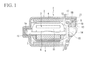
- an electric motor 1 in which a first embodiment of the invention will be described with reference to FIGS. 1 to 5 , is used as a drive unit, such as a wiper motor, a power window motor, and a fan motor of an automobile, and has a bottomed cylindrical yoke 2, magnets 4 fixed onto the inner wall of the yoke 2, and an armature 3 surrounded by the magnets 4, arranged within the yoke 2, and rotatably supported with respect to the yoke 2.
- the magnets 4 are magnetized in four poles, the electric motor 1 is a tetrapolar electric motor, and the number of pole pairs is 2.
- the armature 3 is configured of an armature core 6 fixed onto a rotary shaft 5, an armature coil 7 wound around the armature core 6, and a commutator 13 fixed onto the rotary shaft 5.
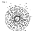
- the armature core 6 is formed by stacking a plurality of metal plates in an axial direction. Eighteen teeth 9 (refer to FIG. 2 ), which are formed in a T shape, are radially formed at regular intervals along a circumferential direction at an outer circumferential portion of a metal plate. As a plurality of metal plates is externally fitted to the rotary shaft 5, a grooved slot 11 is formed between adjacent teeth 9 at an outer circumference of the armature core 6.
- Eighteen slots 11 extend along the axial direction of the rotary shaft 5, and are formed at regular intervals along the circumferential direction.
- a plurality of enamel-coated winding wires 12 is wound between the slots 11, and thereby, an armature coil 7 is formed at the outer circumference of the armature core 6.
- the commutator 13 is fixed onto one end of the rotary shaft 5.
- Eighteen segments 14 formed from a conductive material are attached onto the outer circumferential surface of the commutator 13.
- the segments 14 are made of a plate-like metal piece which is long in the axial direction, and are fixed onto insulated resin in parallel at regular intervals along the circumferential direction in a state where the segments are insulated from each other.
- a riser 15 which is bent in a folded-back fashion is integrally formed at the end of each segment 14 on the side of the armature core 6.
- a winding wire 12, which becomes a winding starting end 30 and a winding finishing end 31 of the winding wire 12 of an armature coil 7, is connected to the riser 15.
- a segment 14 and a winding wire 12 of an armature coil 7 corresponding to this segment are electrically connected to each other.
- the risers 15 respectively corresponding to the segments 14 are each connected by the connecting wires 25.
- the connecting wires 25 are members for short-circuiting a plurality of segments 14 which has the same potential, and are arranged between the commutator 13 and the armature core 6.
- An end 5a of the rotary shaft 5 is supported so as to be freely rotatable by a bearing 16 which is arranged within a boss 2a formed in the yoke 2 so as to protrude therefrom.
- An opening end of the yoke 2 is provided with a cover 17, and a holder stay 18 is attached to the inside of the cover 17.
- Brush holders 19 are formed at three circumferential positions of the holder stay 18. Brushes 21 are built into each of the brush holders 19, so as to protrude and retract from the brush holders 19 in a state where the brushes are pressed via respective coil-shaped springs S.
- the brushes 21 are pressed by the coil-shaped springs S, the tips of the brushes 21 come into sliding contact with the commutator 13, and an electric current is supplied to the commutator 13 via the brushes 21 from an external power source (not shown).
- the springs S are not limited to the coil-shaped springs, and may be a plate-like, i.e., a plate spring.
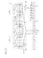
- FIG. 3 is a developed view of the armature
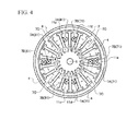
- FIG. 4 is a transverse sectional view of the armature
- a gap between adjacent teeth 9 and 9 corresponds to the slot 11.
- the segments 14 of the commutator 13 and the teeth 9 are each numbered.
- An armature coil 7 of the first embodiment of the invention includes a first conductive wire 110 and a second conductive wire 120.
- the first conductive wire 110 is shown by solid lines
- the second conductive wire 120 is shown by broken lines.
- the armature coil 7 has first to ninth winding wires (61 to 69) formed by the first conductive wire 110 and other first to ninth winding wires (71 to 79) formed by the second conductive wire 120. Also, the first to ninth winding wires (61 to 69) and the other first to ninth winding wires (71 to 79) corresponding thereto are respectively arranged at facing positions which are point symmetric about the rotary shaft 5.
- the first to ninth winding wires are joined together in a series via nine connecting wires 25 which are similarly formed from the first conductive wire 110. That is, the first winding wire 61, the connecting wire 25, the second winding wire 62, the connecting wire 25, the third winding wire 63, the connecting wire 25, the fourth winding wire 64, the connecting wire 25, the fifth winding wire 65, the connecting wire 25, the sixth winding wire 66, the connecting wire 25, the seventh winding wire 67, the connecting wire 25, the eighth winding wire 68, the connecting wire 25, the ninth winding wire 69, and the connecting wire 25 are formed in this order in a series by the first conductive wire 110.
- each connecting wire of the connecting wires 25 which connect the first to ninth winding wires (61 to 69) together is electrically and mechanically connected to the risers 15 and 15 formed by a pair of segments 14 and 14 which is arranged at facing positions which are point symmetric with respect to each other about the rotary shaft 5.
- the other first to ninth winding wires (71 to 79) are joined together in a series via nine connecting wires 25 which are similarly formed from the second conductive wire 120. That is, the first winding wire 71, the connecting wire 25, the second winding wire 72, the connecting wire 25, the third winding wire 73, the connecting wire 25, the fourth winding wire 74, the connecting wire 25, the fifth winding wire 75, the connecting wire 25, the sixth winding wire 76, the connecting wire 25, the seventh winding wire 77, the connecting wire 25, the eighth winding wire 78, the connecting wire 25, the ninth winding wire 79, and the connecting wire 25 are formed in this order in a series by the second conductive wire 120.
- each connecting wire of the connecting wires 25 which connect the other first to ninth winding wires (71 to 79) together is electrically and mechanically connected to the risers 15 and 15 formed by a pair of segments 14 and 14 which is arranged at facing positions which are point symmetric with respect to each other about the rotary shaft 5.
- the first to ninth winding wires (61 to 69) and the other first to ninth winding wires (71 to 79) have a first coil winding wire 7A and a second coil winding wire 7B which are each connected in series to each other. Additionally, the first coil winding wire 7A is wound 12 times so as to surround four teeth 9 which are adjacent to each other, and the second coil winding wire 7B is arranged at a position adjacent in a right direction D 1 to the four teeth 9 around which the first coil winding wire 7A is wound and is wound 12 times so as to surround the four other teeth 9 which are adjacent to each other.
- the winding direction of the second coil winding wire 7B is opposite to the winding direction of the first coil winding wire 7A.
- An end 30 of the first coil winding wire 7A is connected to one segment 14 of the commutator 13, and an end 31 of the second coil winding wire 7B is connected to the segment 14 adjacent to the segment 14 to which the end 30 of the first coil winding wire 7A is connected.
- the second coil winding wire 7B is arranged in the right direction D1 with respect to the first coil winding wire 7A, while the end 31 is connected to the segment 14 arranged in a left direction D2 with respect to the segment 14 to which the end 30 is connected.
- the first conductive wire 110 and second conductive wire 120 are substantially simultaneously wound around the teeth 9, which are formed in the armature core 6 by a double flyer type winding machine and which face each other point-symmetrically about the rotary shaft 5.
- the first to ninth winding wires (61 to 69) and the connecting wires 25 which join the first to ninth winding wires together in a series are formed by the first conductive wire 110, and the other first to ninth winding wires (71 to 79) and the connecting wires 25 which join the other first to ninth winding wires together in a series are formed by the second conductive wire 120.
- the first winding wire 61 formed by the first conductive wire 110 has a first coil winding wire 7A and a second coil winding wire 7B, and the first coil winding wire 7A is joined in a series to a connecting wire 21a similarly formed from the first conductive wire 110, while the second coil winding wire 7B is joined in a series to a connecting wire 25b similarly formed from the first conductive wire 110.
- An end 40 which is a starting point of the connecting wire 25a formed from the first conductive wire 110 is electrically and mechanically connected to the riser 15 formed at the No. 3 segment 14, and as for the connecting wire 25a, an end 41 which is disposed in the left direction D2 and is an end point of the connecting wire 25a is electrically and mechanically connected to the riser 15 formed at the No. 12 segment 14.
- the No. 3 segment 14 and the No. 12 segment 14 are arranged at positions which face each other point-symmetrically about the rotary shaft 5.
- the end 41 of the connecting wire 25a and the end 30 which is the starting point of the first coil winding wire 7A are joined together in series, and the first coil winding wire 7A formed by the first conductive wire 110 is wound around the teeth 9 after being connected to the No. 12 segment 14 at the end 30.
- the first coil winding wire 7A passes through a slit 11 a formed between a No. 18 tooth 9 and a No. 1 tooth 9 and a slit 11b formed between a No. 4 tooth 9 and a No. 5 tooth 9, and is wound 12 times clockwise so as to surround the No. 1 tooth 9 to the No. 4 tooth 9 which are close to each other.
- the arrangement of the second coil winding wire 7B which is formed from the first conductive wire 110 similarly to the first coil winding wire 7A and is connected in series to the first coil winding wire 7A, will be described below.
- the second coil winding wire 7B passes through a slit 11c formed between a No. 8 tooth 9 and a No. 9 tooth 9 and the slit 11 b formed between the No. 4 tooth 9 and the No. 5 tooth 9, is adjacent to the No. 1 tooth 9 to the No. 4 tooth 9, and is wound 12 times in a counterclockwise direction opposite to the winding direction of the first coil winding wire 7A so as to surround the No. 5 tooth 9 to the No. 8 tooth 9 which are close to each other.
- the second coil winding wire 7B is wound in a direction opposite to the first coil winding wire 7A in order to face a magnetic pole having polarity (N pole in FIG. 3 ) different from the polarity (S pole in FIG. 3 ) of a magnetic pole which the first coil winding wire 7A faces.
- the end 31 of the second coil winding wire 7B is connected to the riser 15 formed at the No. 11 segment 14 adjacent to the No. 12 segment 14, to which the end 30 of the first coil winding wire 7A is connected, in the left direction D2 opposite to the right direction D1.
- the first winding wire 61 and the second winding wire 62 wound around the armature core 6 following the first winding wire 61 are joined together in a series by the connecting wire 25b formed by the first conductive wire 110.
- An end 42 which is a starting point of the connecting wire 25b and the end 31 of the second coil winding wire 7B provided at the first winding wire 61 are joined together in a series, and the end 42 is electrically and mechanically connected to the riser 15 of the No. 11 segment 14.
- an end 43 which is disposed in the left direction D2 and is an end point of the connecting wire 25b is electrically and mechanically connected to the riser 15 of the No. 2 segment 14.
- the No. 11 segment 14 and the No. 2 segment 14 are arranged at positions which face each other point-symmetrically about the rotary shaft 5.
- the armature core 6 includes the first to ninth winding wires (61 to 69), and nine connecting wires 25.
- the respective winding wires 12 of the first to ninth winding wires are split into the first coil winding wire 7A and the second coil winding wire 7B, and are wound around the armature core 6. Accordingly, compared to a case where the winding wires are wound without splitting, the number of crossovers 7C which cross over from one slot 11 to another slot 11 is small, and the thickness of the crossovers is small. Additionally, the first to ninth winding wires (61 to 69) and the connecting wires 25 which join the first to ninth winding wires together in a series are formed by disposing a single first conductive wire 110 at the armature core 6 and the commutator 13.
- each of the first to ninth winding wires (61 to 69) formed by the first conductive wire 110 and each of the other first to ninth winding wires (71 to 79) formed by the second conductive wire 120 corresponding to the first to ninth winding wires are substantially simultaneously wound around the teeth 9 of the armature core 6 which face each other point-symmetrically about the rotary shaft 5 by a double flyer type winding machine.
- the respective winding wires 12 of the other first to ninth winding wires (71 to 79) corresponding to the respective winding wires 12 of the first to ninth winding wires (61 to 69) are arranged at positions which face each other point-symmetrically about the rotary shaft 5. That is, the first winding wire 71 is arranged at a position which faces the first winding wire 61, and the second winding wire 72 is arranged at a position which faces the second winding wire 62, the third winding wire 73 is arranged at a position which faces the third winding wire 63, and the fourth winding wire 74 is arranged at a position which faces the fourth winding wire 64.
- the fifth winding wire 75 is arranged at a position which faces the fifth winding wire 65
- the sixth winding wire 76 is arranged at a position which faces the sixth winding wire 66
- the seventh winding wire 77 is arranged at a position which faces the seventh winding wire 67
- the eighth winding wire 78 is arranged at a position which faces the eighth winding wire 68
- the ninth winding wire 79 is arranged at a position which faces the ninth winding wire 69.
- the first winding wire 71 formed by the second conductive wire 120 has a first coil winding wire 7A and a second coil winding wire 7B connected in series to the first coil winding wire 7A, and the first coil winding wire 7A is joined in a series to a connecting wire 21c similarly formed from the second conductive wire 120, while the second coil winding wire 7B is joined in a series to a connecting wire 25d similarly formed from the second conductive wire 120.
- An end 45 which is a starting point of the connecting wire 25c formed from the second conductive wire 120 is electrically and mechanically connected to the riser 15 of the No. 12 segment 14, and as for the connecting wire 25c, an end 46 which is disposed in the left direction D2 and is an end point of the connecting wire 25c is electrically and mechanically connected to the riser 15 of the No. 3 segment 12.
- the No. 12 segment 14 and the No. 3 segment 14 are arranged at positions which face each other point-symmetrically about the rotary shaft 5.
- the end 46 of the connecting wire 25c and the end 34 which is the starting point of the first coil winding wire 7A are joined together in a series, and the first coil winding wire 7A formed by the second conductive wire 120 is wound around the teeth 9 from the end 34.
- the first coil winding wire 7A passes through a slit 11d formed between the No. 9 tooth 9 and a No. 10 tooth 9 and a slit 11e formed between the No. 13 tooth 9 and a No. 14 tooth 9, and is wound 12 times clockwise so as to surround the No. 10 tooth 9 to the No. 13 tooth 9 which are close to each other.
- the arrangement of the second coil winding wire 7B which is formed from the second conductive wire 120 similarly to the first coil winding wire 7A and is connected in series to the first coil winding wire 7A, will be described below.
- the second coil winding wire 7B passes through a slit 11f formed between a No. 17 tooth 9 and the No. 18 tooth 9 and the slit 11e formed between the No. 13 tooth 9 and the No. 14 tooth 9, and is wound 12 times in a counterclockwise direction opposite to the winding direction of the first coil winding wire 7A so as to surround the No. 14 tooth 9 to the No. 17 tooth 9 which are adjacent to the No. 10 tooth 9 to the No. 13 tooth 9 in the right direction D1 and are close to each other.
- the second coil winding wire 7B is wound in a direction opposite to the first coil winding wire 7A because the second coil winding wire 7B faces a magnetic pole having polarity (N pole in FIG. 3 ) different from the polarity (S pole in FIG. 3 ) of a magnetic pole which the first coil winding wire 7A faces.
- the end 35 of the second coil winding wire 7B is connected to the riser 15 formed at the No. 2 segment 14 adjacent to the No. 3 segment 14 to which the end 34 of the first coil winding wire 7A is connected, in the left direction D2 opposite to the right direction D1.
- the first winding wire 71 and the second winding wire 72 are joined together in a series by the connecting wire 25d similarly formed by the second conductive wire 120.
- An end 47 which is a starting point of the connecting wire 25d and the end 35 of the second coil winding wire 7B provided at the first winding wire 71 are joined together in a series, and the end 47 is electrically and mechanically connected to the riser 15 of the No. 2 segment 14.
- an end 48 which is disposed in the left direction D2 and is an end point of the connecting wire 25d is electrically and mechanically connected to the riser 15 of the No. 11 segment 14.
- the No. 2 segment 14 and the No. 11 segment 14 are arranged at positions which face each other point-symmetrically about the rotary shaft 5.
- the end 48 of the connecting wire 25d and an end 36, which is a starting point of the first coil winding wire 7A of the second winding wire 72 wound following the first winding wire 71, are joined together in a series. Also, the first coil winding wire 7A of the second winding wire 72 passes through a slit 11h formed between the No. 17 tooth 9 and the No. 18 tooth 9 and a slit 11i formed between a No. 3 tooth 9 and the No. 4 tooth 9, and is wound 12 times clockwise so as to surround the No. 18 tooth 9 to the No. 3 tooth.
- the armature core 6 includes the other first to ninth winding wires (71 to 79), and nine connecting wires 25.
- the respective winding wires 12 of the other first to ninth winding wires (71 to 79) are split into the first coil winding wire 7A and the second coil winding wire 7B, and are wound around the armature core 6. Accordingly, compared to a case where the winding wires are wound without splitting, the thickness of crossovers 7C which cross over from one slot 11 to another slot 11 is made small. Additionally, the other first to ninth winding wires (71 to 79) and the connecting wires 25 which join the other first to ninth winding wires together in a series are formed by disposing a single first winding wire 71 at the armature core 6 and the commutator 13.
- the respective winding wires 12 of the first to ninth winding wires (61 to 69) and the other first to ninth winding wires (71 to 79) are split into the first coil winding wire 7A and the second coil winding wire 7B, and are wound around the armature core 6, and the thickness of the respective crossovers 7C is made thin. Therefore, in the armature coil 7 formed by the first to ninth winding wires (61 to 69) and the other first to ninth winding wires (71 to 72) which are each wound so as to overlap each other sequentially from the outside of the winding wires 12 which are already wound, winding thickening caused by overlapping of the crossovers 7C is reduced.
- the first winding wire 61 and the first winding wire 71 which are arranged at positions which face each other point-symmetrically about the rotary shaft 5 are connected to each other by the connecting wire 25a and the connecting wire 25c. Therefore, the first winding wire 61 and the first winding wire 71 are connected in parallel to each other by the connecting wire 25a and the connecting wire 25c.
- the winding wires 12 and 12 which are arranged at positions which face each other point-symmetrically about the rotary shaft 5 among the first to ninth winding wires (61 to 69) and the other first to ninth winding wires (71 to 79), are each connected in parallel to each other by two connecting wires 25 and 25. For this reason, even in the four-pole electric motor 1 as in the present embodiment, basically, the armature 3 can be rotated by supplying power from two positions arranged with an electrical angle of 180°.
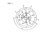
- the brush 21 is constituted by a brush 21 a for low speed and a brush 21b for high speed which are selectively connected to a cathode (first power supply terminal) of a power source, and a common brush 21c which is used by both the brush 21a for low speed or the brush 21b for high speed, and is connected to an anode (second power supply terminal) of the power source.
- the brush 21a for low speed and the common brush 21c are mutually disposed at an interval of 180° in electrical angle and at an interval of 90° in the circumferential direction in mechanical angle.
- the brush 21b for high speed is arranged to be apart from the brush 21a for low speed by an angle ⁇ in the circumferential direction.
- the common brush 21c is connected to the anode (second power supply terminal) of the power source and the brush 21a for low speed and the brush 21b for high speed are connected to the cathode (first power supply terminal).
- these brushes may be connected in the opposite manner to this.
- the segments 14 which have the same potential in the commutator 13, i.e., the segments which are arranged to face each other point-symmetrically about the rotary shaft 5 are short-circuited by the connecting wire 25, electric power is supplied even to the segments with which the brushes 21 do not come into sliding contact via the connecting wires 25. Accordingly, as shown by one-dot chain lines in FIG. 5 , an electric current is supplied to the segments 14 which have the same potential so that there are brushes 21a', 21b', and 21c' even at positions which face the brushes 21a, 21b, and 21 c, respectively, about the rotary shaft 5.
- the brush 21b' for high speed exists at a position which is advanced by an angle ⁇ with respect to the brush 21a for low speed.
- an electric current is supplied by the common brush 21c and the brush 21a for low speed during low-speed rotation, and an electric current is supplied by the common brush 21c and the brush 21b for high speed during high-speed rotation.
- the electric motor 1 is advanced by the brush 21b for high-speed, and operates at higher rotational speed than that during low-speed rotation.
- the advance angle ⁇ is to 20° to 35° in the present embodiment.
- the commutator 13 is provided with the connecting wires 25 which short circuits the segments 14 to have the same potential together, it is possible to provide an electric motor 1 which can switch rotational speed by installing three brushes of the brush 21a for low speed, the brush 21b for high speed which is arranged to be separated from the brush 21 a for low speed by the angle ⁇ in the circumferential direction, and the common brush 21c by which is used by both the brush 21a for low speed and the brush 21b for high speed. Moreover, since the number of brushes does not increase even if the number of pole pairs is 2, the manufacturing cost of the electric motor 1 does not increase.
- FIG. 6 is a view illustrating torque ripple generated in the armature when the armature 3 is arranged at a certain position.
- lines of magnetic flux ( ⁇ 1 to * ⁇ 4) which are each inclined in the thrust direction (circumferential direction) are generated between a No. 2 tooth 9 and a magnet 4b, between a No. 7 tooth 9 and the magnet 4c, between a No. 11 tooth 9 and a magnet 4d, and between a No. 16 tooth 9 and the magnet 4a.
- the number of teeth 9 is “18", the number of pole pairs is “2", and the number of teeth 9 is “9” times the number of pole pairs.
- torques (T1 to T4) adjacent to each other among the torques (T1 to T4) act in different rotational directions. That is, in this drawing, the torque T1 and the torque T3 act counterclockwise, and the torque T2 and the torque T4 act clockwise. Therefore, the torque T1 and the torque T3, and the torque T2 and the torque T4 will be mutually cancelled out. Due to this, the torque ripple which is the total of the torques (T1 to T4) is reduced, and the torque ripple becomes small.
- the torque ripple becomes one of the causes of noise and vibration in the electric motor. Additionally, the size of the torque ripple, and the magnitude of noise and vibration have a proportional relationship. Accordingly, since the torque ripple is reduced as in the present embodiment, the noise and vibration in the electric motor 1 can be reduced.
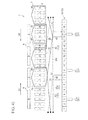
- FIG. 7 is a developed view of the armature
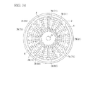
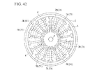
- FIG. 8 is a transverse sectional view of the armature
- a gap between adjacent teeth 9 and 9 corresponds to the slot 11.
- the segments 14 of the commutator 13 and the teeth 9 are each numbered.
- the electric motor 1 of the second embodiment of the present invention and the electric motor 1 of the first embodiment described above are different from each other only in the winding structure of the armature coil 7, and are the same in the other portions. Accordingly, only the winding structure of the armature coil 7 will be described below, and description of the other portions is omitted.
- the armature coil 7 of the second embodiment of the present invention includes a first conductive wire 110 and a second conductive wire 120.
- first conductive wire 110 is shown by solid lines
- second conductive wire 120 is indicated by broken lines.
- the armature coil 7 has first to ninth winding wires (61 to 69) formed by the first conductive wire 110 and other first to ninth winding wires (71 to 79) formed by the second conductive wire 120. Also, the first to ninth winding wires (61 to 69) and the other first to ninth winding wires (71 to 79) corresponding thereto are respectively arranged at facing positions which are point symmetric about the rotary shaft 5.
- the first to ninth winding wires are joined together in a series via nine connecting wires 25 which are similarly formed from the first conductive wire 110. That is, the first winding wire 61, the connecting wire 25, the second winding wire 62, the connecting wire 25, the third winding wire 63, the connecting wire 25, the fourth winding wire 64, the connecting wire 25, the fifth winding wire 65, the connecting wire 25, the sixth winding wire 66, the connecting wire 25, the seventh winding wire 67, the connecting wire 25, the eighth winding wire 68, the connecting wire 25, the ninth winding wire 69, and the connecting wire 25 are formed in this order in a series by the first conductive wire 110.
- each connecting wire of the connecting wires 25 which connect the first to ninth winding wires (61 to 69) together is electrically and mechanically connected to the risers 15 and 15 formed at a pair of segments 14 and 14 which is arranged at facing positions which are point symmetric with respect to each other about the rotary shaft 5.
- the other first to ninth winding wires (71 to 79) are joined together in a series via nine connecting wires 25 which are similarly formed from the second conductive wire 120. That is, the first winding wire 71, the connecting wire 25, the second winding wire 72, the connecting wire 25, the third winding wire 73, the connecting wire 25, the fourth winding wire 74, the connecting wire 25, the fifth winding wire 75, the connecting wire 25, the sixth winding wire 76, the connecting wire 25, the seventh winding wire 77, the connecting wire 25, the eighth winding wire 78, the connecting wire 25, the ninth winding wire 79, and the connecting wire 25 are formed in this order in a series by the second conductive wire 120.
- each connecting wire of the connecting wires 25 which connect the other first to ninth winding wires (71 to 79) together is electrically and mechanically connected to the risers 15 and 15 formed at a pair of segments 14 and 14 which is arranged at facing positions which are point symmetric with respect to each other about the rotary shaft 5.
- first to ninth winding wires (61 to 69) and the other first to ninth winding wires (71 to 79) have a first coil winding wire 7A and a second coil winding wire 7B which are each connected in series to each other. Additionally, the first coil winding wire 7A is wound 12 times so as to surround four teeth 9 which are adjacent to each other, and the second coil winding wire 7B is arranged at a position adjacent in the right direction D 1 to the four teeth 9 around which the first coil winding wire 7A is wound with one tooth 9 therebetween and is wound 12 times so as to surround the four other teeth 9 which are adjacent to each other.
- the winding direction of the second coil winding wire 7B is opposite to the winding direction of the first coil winding wire 7A.
- An end 30 of the first coil winding wire 7A is connected to one segment 14 of the commutator 13, and an end 31 of the second coil winding wire 7B is connected to the segment 14 adjacent to the segment 14 to which the end 30 of the first coil winding wire 7A is connected.
- the second coil winding wire 7B is arranged in the right direction D1 with respect to the first coil winding wire 7A, while the end 31 is connected to the segment 14 arranged in the left direction D2 with respect to the segment 14 to which the end 30 is connected.
- the first conductive wire 110 and the second conductive wire 120 are substantially simultaneously wound around the teeth 9, which are formed in the armature core 6 by a double flyer type winding machine and which face each other point-symmetrically about the rotary shaft 5.
- the first to ninth winding wires (61 to 69) and the connecting wires 25 which join the first to ninth winding wires together in a series are formed by the first conductive wire 110, and the other first to ninth winding wires (71 to 79) and the connecting wires 25 which join the other first to ninth winding wires together in a series are formed by the second conductive wire 120.
- the first winding wire 61 formed by the first conductive wire 110 has a first coil winding wire 7A and a second coil winding wire 7B, and the first coil winding wire 7A is joined in a series to a connecting wire 21 a similarly formed from the first conductive wire 110, while the second coil winding wire 7B is joined in a series to a connecting wire 25b similarly formed from the first conductive wire 110.
- An end 40 which is a starting point of the connecting wire 25a formed from the first conductive wire 110 is electrically and mechanically connected to the riser 15 formed at the No. 3 segment 14, and as for the connecting wire 25a, an end 41 which is disposed in the left direction D2 and is an end point of the connecting wire 25a is electrically and mechanically connected to the riser 15 formed at the No. 12 segment 14.
- the No. 3 segment 14 and the No. 12 segment 14 are arranged at positions which face each other point-symmetrically about the rotary shaft 5.
- the end 41 of the connecting wire 25a and the end 30 which is the starting point of the first coil winding wire 7A are joined together in a series, and the first coil winding wire 7A formed by the first conductive wire 110 is wound around the teeth 9 after being connected to the end 30.
- the first coil winding wire 7A passes through a slit 11a formed between the No. 18 tooth 9 and the No. 1 tooth 9 and a slit 11b formed between the No. 4 tooth 9 and the No. 5 tooth 9, and is wound 12 times clockwise so as to surround the No. 1 tooth 9 to the No. 4 tooth 9 which are close to each other.
- the arrangement of the second coil winding wire 7B which is formed from the first conductive wire 110 similarly to the first coil winding wire 7A and is connected in series to the first coil winding wire 7A, will be described below.
- the second coil winding wire 7B passes through a slit 11d formed between the No. 9 tooth 9 and the No. 10 tooth 9 and the slit 11c formed between the No. 5 tooth 9 and the No. 6 tooth 9, and is wound 12 times in a counterclockwise direction opposite to the winding direction of the first coil winding wire 7A so as to surround the No. 6 tooth 9 to the No. 9 tooth 9 which are adjacent to the No. 1 tooth 9 to the No. 4 tooth 9 with the No. 5 tooth 9 therebetween and are close to each other.
- the second coil winding wire 7B is wound in a direction opposite to the first coil 7 winding wire 7A because the second coil winding wire 7B faces a magnetic pole having polarity (N pole in FIG. 7 ) different from the polarity (S pole in FIG. 7 ) of a magnetic pole which the first coil winding wire 7A faces.
- the end 31 of the second coil winding wire 7B is connected to the riser 15 formed at the No. 11 segment 14 adjacent to the No. 12 segment 14 to which the end 30 of the first coil winding wire 7A is connected, in the left direction D2 opposite to the right direction D1.
- the first winding wire 61 and the second winding wire 62 wound around the armature core 6 following the first winding wire 61 are joined together in a series by the connecting wire 25b formed by the first conductive wire 110.
- An end 42 which is a starting point of the connecting wire 25b and the end 31 of the second coil winding wire 7B provided at the first winding wire 61 are joined together in a series, and the end 42 is electrically and mechanically connected to the riser 15 of the No. 11 segment 14.
- an end 43 which is disposed in the left direction D2 and is an end point of the connecting wire 25b is electrically and mechanically connected to the riser 15 of the No. 2 segment 14.
- the No. 11 segment 14 and the No. 2 segment 14 are arranged at positions which face each other point-symmetrically about the rotary shaft 5.
- the armature core 6 includes the first to ninth winding wires (61 to 69), and nine connecting wires 25.
- the respective winding wires 12 of the first to ninth winding wires are split into the first coil winding wire 7A and the second coil winding wire 7B, and are wound around the armature core 6. Accordingly, compared to a case where the winding wires are wound without splitting, the number of crossovers 7C which cross over from one slot 11 to another slot 11 is small, and the thickness of the crossovers is small. Additionally, the first to ninth winding wires (61 to 69) and the connecting wires 25 which join the first to ninth winding wires together in a series are formed by disposing a single first conductive wire 110 at the armature core 6 and the commutator 13.
- each of the first to ninth winding wires (61 to 69) formed by the first conductive wire 110 and each of the other first to ninth winding wires (71 to 79) formed by the second conductive wire 120 corresponding to the first to ninth winding wires are substantially simultaneously wound around the teeth 9 of the armature core 6 which face each other point-symmetrically about the rotary shaft 5 by a double flyer type winding machine.
- the respective winding wires 12 of the other first to ninth winding wires (71 to 79) corresponding to the respective winding wires 12 of the first to ninth winding wires (61 to 69) are arranged at positions which face each other point-symmetrically about the rotary shaft 5. That is, the first winding wire 71 is arranged at a position which faces the first winding wire 61, and the second winding wire 72 is arranged at a position which faces the second winding wire 62, the third winding wire 73 is arranged at a position which faces the third winding wire 63, and the fourth winding wire 74 is arranged at a position which faces the fourth winding wire 64.
- the fifth winding wire 75 is arranged at a position which faces the fifth winding wire 65
- the sixth winding wire 76 is arranged at a position which faces the sixth winding wire 66
- the seventh winding wire 77 is arranged at a position which faces the seventh winding wire 67
- the eighth winding wire 78 is arranged at a position which faces the eighth winding wire 68
- the ninth winding wire 79 is arranged at a position which faces the ninth winding wire 69.
- first to ninth winding wires (71 to 79) and the connecting wires 25 which join the other first to ninth winding wires together in a series, which are formed by the second conductive wire 120, will be described from the first winding wire 71.
- the first winding wire 71 formed by the second conductive wire 120 has a first coil winding wire 7A and a second coil winding wire 7B connected in series to the first coil winding wire 7A, and the first coil winding wire 7A is joined in a series to a connecting wire 21 similarly formed from the second conductive wire 120, while the second coil winding wire 7B is joined in a series to a connecting wire 25d similarly formed from the second conductive wire 120.
- An end 45 which is a starting point of the connecting wire 25c formed from the second conductive wire 120 is electrically and mechanically connected to the riser 15 of the No. 12 segment 14, and as for the connecting wire 25c, an end 46 which is disposed in the left direction D2 and is an end point of the connecting wire 25c is electrically and mechanically connected to the riser 15 of the No. 3 segment 12.
- the No. 12 segment 14 and the No. 3 segment 14 are arranged at positions which face each other point-symmetrically about the rotary shaft 5.
- the end 46 of the connecting wire 25c and the end 34 which is the starting point of the first coil winding wire 7A are joined together in a series, and the first coil winding wire 7A formed by the second conductive wire 120 is wound around the teeth 9 from the end 34.
- the first coil winding wire 7A passes through a slit 11d formed between the No. 9 tooth 9 and the No. 10 tooth 9 and a slit 11e formed between the No. 13 tooth 9 and the No. 14 tooth 9, and is wound 12 times clockwise so as to surround the No. 10 tooth 9 to the No. 13 tooth 9 which are close to each other.
- the arrangement of the second coil winding wire 7B which is formed from the second conductive wire 120 similarly to the first coil winding wire 7A and is connected in series to the first coil winding wire 7A, will be described below.
- the second coil winding wire 7B passes through the slit 11a formed between the No. 18 tooth 9 and the No. 1 tooth 9 and the slit 11f formed between the No. 14 tooth 9 and the No. 15 tooth 9, and is wound 12 times in a counterclockwise direction opposite to the winding direction of the first coil winding wire 7A so as to surround the No. 15 tooth 9 to the No. 18 tooth 9 which are adjacent to the No. 10 tooth 9 to the No. 13 tooth 9 in the right direction D1 with the No. 14 tooth 9 therebetween and are close to each other.
- the second coil winding wire 7B is wound in a direction opposite to the first coil 7 winding wire A in order to face a magnetic pole having polarity (N pole in FIG. 7 ) different from the polarity (S pole in FIG. 7 ) of a magnetic pole which the first coil winding wire 7A faces.
- the end 35 of the second coil winding wire 7B is connected to the riser 15 formed at the No. 2 segment 14 adjacent to the No. 3 segment 14 to which the end 34 of the first coil winding wire 7A is connected, in the left direction D2 opposite to the right direction D1.
- the first winding wire 71 and the second winding wire 72 are joined together in a series by the connecting wire 25d similarly formed by the second conductive wire 120.
- An end 47 which is a starting point of the connecting wire 25d and the end 35 of the second coil winding wire 7B provided at the first winding wire 71 are joined together in a series, and the end 47 is electrically and mechanically connected to the riser 15 of the No. 2 segment 14.
- an end 48 which is disposed in the left direction D2 and is an end point of the connecting wire 25d, is electrically and mechanically connected to the riser 15 of the No. 11 segment 14.
- the No. 2 segment 14 and the No. 11 segment 14 are arranged at positions which face each other point-symmetrically about the rotary shaft 5.
- the end 48 of the connecting wire 25d and an end 36, which is a starting point of the first coil winding wire 7A of the second winding wire 72 wound following the first winding wire 71, are joined together in a series. Also, the first coil winding wire 7A of the second winding wire 72 passes through a slit 11f formed between the No. 17 tooth 9 and the No. 18 tooth 9 and the slit 11h formed between a No. 3 tooth 9 and the No. 4 tooth 9, and is wound 12 times clockwise so as to surround the No. 18 tooth 9 to the No. 3 tooth 9.
- the armature core 6 includes the other first to ninth winding wires (71 to 79), and nine connecting wires 25.
- the respective winding wires 12 of the other first to ninth winding wires (71 to 79) are split into the first coil winding wire 7A and the second coil winding wire 7B, and are wound around the armature core 6. Accordingly, compared to a case where the winding wires are wound without splitting, the thickness of crossovers 7C which cross over from one slot 11 to another slot 11 is made small. Additionally, the other first to ninth winding wires (71 to 79) and the connecting wires 25 which join the other first to ninth winding wires together in a series are formed by disposing a single first winding wire 71 at the armature core 6 and the commutator 13.
- the respective winding wires 12 of the first to ninth winding wires (61 to 69) and the other first to ninth winding wires (71 to 79) are split into the first coil winding wire 7A and the second coil winding wire 7B, and are wound around the armature core 6, and the thickness of the respective crossovers 7C is made thin. Therefore, in the armature coil 7 formed by the first to ninth winding wires (61 to 69) and the other first to ninth winding wires (71 to 72) which are each wound so as to overlap each other sequentially from the outside of the winding wires 12 which are already wound, winding thickening caused by overlapping of the crossovers 7C is reduced.
- the first winding wire 61 and the other first winding wire 71 which are arranged at positions which face each other point-symmetrically about the rotary shaft 5 are connected to each other by the connecting wire 25a and the connecting wire 25c. Therefore, the first winding wire 61 and the other first winding wire 71 are connected in parallel to each other by the connecting wire 25a and the connecting wire 25c.
- the winding wires 12 and 12 which are arranged at positions which face each other point-symmetrically about the rotary shaft 5 among the first to ninth winding wires (61 to 69) and the other first to ninth winding wires (71 to 79), are each connected in parallel to each other by two connecting wires 25 and 25. For this reason, even in the four-pole electric motor 1 as in the present embodiment, basically, the armature 3 can be rotated by supplying power from two positions arranged with an electrical angle of 180°.
- FIG. 9 is a developed view of the armature
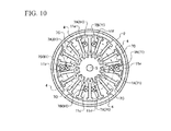
- FIG. 10 is a transverse sectional view of the armature
- a gap between adjacent teeth 9 corresponds to the slot 11.
- the segments 14 provided at the commutator 13 and the teeth 9 provided at the armature core 6 are each numbered.
- the electric motor 1 of the third embodiment of the present invention and the electric motor 1 of the first embodiment described above are different from each other only in the winding structure of the armature coil 7, and are the same in the other portions. Accordingly, only the winding structure of the armature coil 7 will be described below, and description of the other portions is omitted.
- the armature coil 7 of the third embodiment of the present invention includes a first conductive wire 110 and a second conductive wire 120.
- first conductive wire 110 is shown by solid lines
- second conductive wire 120 is indicated by broken lines.
- the armature coil 7 has first to ninth winding wires (61 to 69) formed by the first conductive wire 110 and other first to ninth winding wires (71 to 79) formed by the second conductive wire 120. Also, the first to ninth winding wires (61 to 69) and the other first to ninth winding wires (71 to 79) corresponding thereto are respectively arranged at facing positions which are point symmetric about the rotary shaft 5.
- a first winding wire pair (61, 71), a second winding wire pair (62, 72), a third winding wire pair (63, 73), a fourth winding wire pair (64, 74), a fifth winding wire pair (65, 75), a sixth winding wire pair (66, 76), a seventh winding wire pair (67, 77), an eighth winding wire pair (68, 78), and a ninth winding wire pair (69, 79) are respectively arranged at facing positions which are point symmetric about the rotary shaft 5.
- the first to ninth winding wires are joined together in a series via nine connecting wires 25 which are similarly formed from the first conductive wire 110. That is, the first winding wire 61, the connecting wire 25, the second winding wire 62, the connecting wire 25, the third winding wire 63, the connecting wire 25, the fourth winding wire 64, the connecting wire 25, the fifth winding wire 65, the connecting wire 25, the sixth winding wire 66, the connecting wire 25, the seventh winding wire 67, the connecting wire 25, the eighth winding wire 68, the connecting wire 25, the ninth winding wire 69, and the connecting wire 25 are respectively formed in this order in a series by the first conductive wire 110.
- each connecting wire of the connecting wires 25 which connect the first to ninth winding wires (61 to 69) together is electrically and mechanically connected to the risers 15 formed by a pair of segments 14 and 14 which is arranged at facing positions which are point symmetric with respect to each other about the rotary shaft 5.
- the other first to ninth winding wires (71 to 79) are joined together in a series via nine connecting wires 25 which are similarly formed from the second conductive wire 120. That is, the first winding wire 71, the connecting wire 25, the second winding wire 72, the connecting wire 25, the third winding wire 73, the connecting wire 25, the fourth winding wire 74, the connecting wire 25, the fifth winding wire 75, the connecting wire 25, the sixth winding wire 76, the connecting wire 25, the seventh winding wire 77, the connecting wire 25, the eighth winding wire 78, the connecting wire 25, the ninth winding wire 79, and the connecting wire 25 are formed in this order in a series by the second conductive wire 120.
- each connecting wire of the connecting wires 25 which connect the other first to ninth winding wires (71 to 79) together is electrically and mechanically connected to the risers 15 formed by a pair of segments 14 and 14 which is arranged at facing positions which are point symmetric with respect to each other about the rotary shaft 5.
- the first to ninth winding wires (61 to 69) and the other first to ninth winding wires (71 to 79) have a first coil winding wire 7A and a second coil winding wire 7B which are each connected in series to each other. Additionally, the first coil winding wire 7A is wound 12 times so as to surround four teeth 9 which are adjacent to each other, and the second coil winding wire 7B is arranged at a position adjacent in the right direction D1 to the four teeth 9 around which the first coil winding wire 7A is wound, and is wound 12 times so as to surround the four other teeth 9 which are adjacent to each other.
- the winding direction of the second coil winding wire 7B is opposite to the winding direction of the first coil winding wire 7A.
- An end 30 of the first coil winding wire 7A is connected to one segment 14 of the commutator 13, and an end 31 of the second coil winding wire 7B is connected to the segment 14 adjacent in the right direction D1 to the segment 14 arranged at a position which is point symmetric about the rotary shaft 5 with respect to the segment 14 to which the end 30 of the first coil winding wire 7A is connected.
- the first conductive wire 110 and second conductive wire 120 are substantially simultaneously wound around the teeth 9, which are formed in the armature core 6 by a double flyer type winding machine and which face each other point-symmetrically about the rotary shaft 5.
- the first to ninth winding wires (61 to 69) and the connecting wires 25 which join the first to ninth winding wires together in a series are formed by the first conductive wire 110, and the other first to ninth winding wires (71 to 79) and the connecting wires 25 which join the other first to ninth winding wires together in a series are formed by the second conductive wire 120.
- the first winding wire 61 formed by the first conductive wire 110 has a first coil winding wire 7A and a second coil winding wire 7B, and the first coil winding wire 7A is joined in a series to a connecting wire 21 a similarly formed from the first conductive wire 110, while the second coil winding wire 7B is joined in a series to a connecting wire 25b similarly formed from the first conductive wire 110.
- An end 40 which is a starting point of the connecting wire 25a formed from the first conductive wire 110 is electrically and mechanically connected to the riser 15 formed at the No. 15 segment 14, and as for the connecting wire 25a, an end 41 which is disposed in the left direction D2 and is an end point of the connecting wire 25a is electrically and mechanically connected to the riser 15 formed at the No. 6 segment 14.
- the No. 15 segment 14 and the No. 6 segment 14 are arranged at positions which face each other point-symmetrically about the rotary shaft 5.
- the end 41 of the connecting wire 25a and the end 30 which is the starting point of the first coil winding wire 7A are joined together in a series, and the first coil winding wire 7A formed by the first conductive wire 110 is wound around the teeth 9 after being connected to the end 30.
- the first coil winding wire 7A passes through a slit 11 a formed between the No. 18 tooth 9 and the No. 1 tooth 9 and a slit 11b formed between the No. 4 tooth 9 and the No. 5 tooth 9, and is wound 12 times clockwise so as to surround the four No. 1 to No. 4 teeth 9 which are close to each other.
- the arrangement of the second coil winding wire 7B which is formed from the first conductive wire 110 similarly to the first coil winding wire 7A and is connected in series to the first coil winding wire 7A, will be described below.
- the second coil winding wire 7B passes through a slit 11c formed between a No. 8 tooth 9 and a No. 9 tooth 9 and the slit 11b formed between the No. 4 tooth 9 and the No. 5 tooth 9, and is wound 12 times in a counterclockwise direction opposite to the winding direction of the first coil winding wire 7A so as to surround the four No. 5 to No. 8 teeth 9 which are adjacent to the No. 1 to No. 4 teeth 9 and are close to each other.
- the second coil winding wire 7B is wound in a direction opposite to the first coil 7 winding wire A because the second coil winding wire 7B faces a magnetic pole having polarity (S pole in FIG. 9 ) different from the polarity (N pole in FIG. 9 ) of a magnetic pole which the first coil winding wire 7A faces.
- the end 31 of the second coil winding wire 7B is connected to the riser 15 formed at the No. 16 segment 14 adjacent in the right direction D1 to the No. 15 segment 14 arranged at a position which is point symmetric about the rotary shaft 5 with respect to the No. 6 segment 14 to which the end 30 of the first coil winding wire 7A is connected.
- the first winding wire 61 and the second winding wire 62 wound around the armature core 6 following the first winding wire 61 are joined together in a series by the connecting wire 25b formed by the first conductive wire 110.
- An end 42 which is a starting point of the connecting wire 25b and the end 31 of the second coil winding wire 7B provided at the first winding wire 61 are joined together in a series, and the end 42 is electrically and mechanically connected to the riser 15 of the No. 16 segment 14.
- an end 43 which is disposed in the left direction D2 and is an end point of the connecting wire 25b is electrically and mechanically connected to a riser 15 formed at a No. 7 segment 14.
- the No. 16 segment 14 and the No. 7 segment 14 are arranged at positions which face each other point-symmetrically about the rotary shaft 5.
- the respective winding wires 12 of the first to ninth winding wires are split into the first coil winding wire 7A and the second coil winding wire 7B, and are wound around the armature core 6. Accordingly, compared to a case where the winding wires are wound without splitting, the number of crossovers 7C which cross over from one slot 11 to another slot 11 is small, and the thickness of the crossovers is small. Additionally, the first to ninth winding wires (61 to 69) and the connecting wires 25 which join the first to ninth winding wires together in a series are formed by disposing a single first conductive wire 110 at the armature core 6 and the commutator 13.
- each of the first to ninth winding wires (61 to 69) formed by the first conductive wire 110 and each of the other first to ninth winding wires (71 to 79) formed by the second conductive wire 120 corresponding to the first to ninth winding wires are substantially simultaneously wound around the teeth 9 of the armature core 6 which face each other point-symmetrically about the rotary shaft 5 by a double flyer type winding machine.
- the respective winding wires 12 of the other first to ninth winding wires (71 to 79) corresponding to the respective winding wires 12 of the first to ninth winding wires (61 to 69) are arranged at positions which face each other point-symmetrically about the rotary shaft 5. That is, the first winding wire 71 is arranged at a position which faces the first winding wire 61, and the second winding wire 72 is arranged at a position which faces the second winding wire 62, the third winding wire 73 is arranged at a position which faces the third winding wire 63, and the fourth winding wire 74 is arranged at a position which faces the fourth winding wire 64.
- the fifth winding wire 75 is arranged at a position which faces the fifth winding wire 65
- the sixth winding wire 76 is arranged at a position which faces the sixth winding wire 66
- the seventh winding wire 77 is arranged at a position which faces the seventh winding wire 67
- the eighth winding wire 78 is arranged at a position which faces the eighth winding wire 68
- the ninth winding wire 79 is arranged at a position which faces the ninth winding wire 69.
- first to ninth winding wires (71 to 79) and the connecting wires 25 which join the other first to ninth winding wires together in a series, which are formed by the second conductive wire 120, will be described from the first winding wire 71.
- the first winding wire 71 formed by the second conductive wire 120 has a first coil winding wire 7A and a second coil winding wire 7B connected in series to the first coil winding wire 7A, and the first coil winding wire 7A is joined in a series to a connecting wire 21c similarly formed from the second conductive wire 120, while the second coil winding wire 7B is joined in a series to a connecting wire 25d similarly formed from the second conductive wire 120.
- An end 45 which is a starting point of the connecting wire 25c formed from the second conductive wire 120 is electrically and mechanically connected to the riser 15 formed at the No. 6 segment 14, and as for the connecting wire 25c, an end 46 which is disposed in the left direction D2 and is an end point of the connecting wire 25c is electrically and mechanically connected to the riser 15 of the No. 15 segment 14.
- the No. 6 segment 14 and the No. 15 segment 14 are arranged at positions which face each other point-symmetrically about the rotary shaft 5.
- the end 46 of the connecting wire 25c and the end 34 which is the starting point of the first coil winding wire 7A are joined together in a series, and the first coil winding wire 7A formed by the second conductive wire 120 is wound around the teeth 9 from the end 34.
- the first coil winding wire 7A passes through a slit 11 d formed between the No. 9 tooth 9 and the No. 10 tooth 9 and a slit 11e formed between the No. 13 tooth 9 and the No. 14 tooth 9, and is wound 12 times clockwise so as to surround the four No. 10 to No. 13 teeth 9 which are close to each other.
- the arrangement of the second coil winding wire 7B which is formed from the second conductive wire 120 similarly to the first coil winding wire 7A and is connected in series to the first coil winding wire 7A, will be described below.
- the second coil winding wire 7B passes through a slit 1 If formed between the No. 17 tooth 9 and the No. 18 tooth 9 and the slit 11 e formed between the No. 13 tooth 9 and the No. 14 tooth 9, and is wound 12 times in a counterclockwise direction opposite to the winding direction of the first coil winding wire 7A so as to surround the four No. 14 to No. 17 teeth 9 which are adjacent to the four No. 10 to No. 13 teeth 9 in the right direction D1 and are close to each other.
- the second coil winding wire 7B is wound in a direction opposite to the first coil winding wire 7A because the second coil winding wire 7B faces a magnetic pole having polarity (S pole in FIG. 9 ) different from the polarity (N pole in FIG. 9 ) of a magnetic pole which the first coil winding wire 7A faces.
- the end 35 of the second coil winding wire 7B is connected to the riser 15 formed at the No. 7 segment 14 adjacent in the right direction D1 to the No. 6 segment 14 arranged at a position which is point symmetric about the rotary shaft 5 with respect to the No. 15 segment 14 to which the end 34 of the first coil winding wire 7A is connected.
- the first winding wire 71 and the second winding wire 72 are joined together in a series by the connecting wire 25d similarly formed by the second conductive wire 120.
- An end 47 which is a starting point of the connecting wire 25d and the end 35 of the second coil winding wire 7B provided at the first winding wire 71 are joined together in a series, and the end 47 is electrically and mechanically connected to the riser 15 of the No. 7 segment 14.
- an end 48 disposed in the left direction D2 which is an end point of the connecting wire 25d is electrically and mechanically connected to the riser 15 of the No. 16 segment 14.
- the No. 7 segment 14 and the No. 16 segment 14 are arranged at positions which face each other point-symmetrically about the rotary shaft 5.
- the end 48 of the connecting wire 25d and an end 36, which is a starting point of the first coil winding wire 7A of the second winding wire 72 wound following the first winding wire 71, are joined together in a series. Also, the first coil winding wire 7A of the second winding wire 72 passes through a slit 11i formed between the No. 10 tooth 9 and the No. 11 tooth 9 and the slit 11j formed between the No. 14 tooth 9 and the No. 15 tooth 9, and is wound 12 times clockwise so as to surround the four No. 11 to No. 14 teeth 9.
- the armature core 6 includes the other first to ninth winding wires (71 to 79), and nine connecting wires 25.
- the respective winding wires 12 of the other first to ninth winding wires (71 to 79) are split into the first coil winding wire 7A and the second coil winding wire 7B, and are wound around the armature core 6. Accordingly, compared to a case where the winding wires are wound without splitting, the thickness of crossovers 7C which cross over from one slot 11 to another slot 11 is made small. Additionally, the other first to ninth winding wires (71 to 79) and the connecting wires 25 which join the other first to ninth winding wires together in a series are formed by disposing a single first winding wire 71 at the armature core 6 and the commutator 13.
- the respective winding wires 12 of the first to ninth winding wires (61 to 69) and the other first to ninth winding wires (71 to 79) are split into the first coil winding wire 7A and the second coil winding wire 7B, and are wound around the armature core 6, and the thickness of the respective crossovers 7C is made thin. Therefore, in the armature coil 7 formed by the first to ninth winding wires (61 to 69) and the other first to ninth winding wires (71 to 72) which are each wound so as to overlap each other sequentially from the outside of the winding wires 12 which are already wound, winding thickening caused by overlapping of the crossovers 7C is reduced.
- the first winding wire 61 and the first winding wire 71 which are arranged at positions which face each other point-symmetrically about the rotary shaft 5 are connected to each other by the connecting wire 25a and the connecting wire 25c. Therefore, the first winding wire 61 and the first winding wire 71 are connected in parallel to each other by the connecting wire 25a and the connecting wire 25c.
- the winding wires 12 and 12 which are arranged at positions which face each other point-symmetrically about the rotary shaft 5 among the first to ninth winding wires (61 to 69) and the other first to ninth winding wires (71 to 79), are each connected in parallel to each other by two connecting wires 25 and 25. For this reason, even in the four-pole electric motor 1 as in the present embodiment, basically, the armature 3 can be rotated by supplying power from two positions arranged with an electrical angle of 180°.
- FIG. 11 is a developed view of the armature
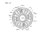
- FIG. 12 is a transverse sectional view of the armature
- a gap between adjacent teeth 9 corresponds to the slot 11.
- the segments 14 provided at the commutator 13 and the teeth 9 provided at the armature core 6 are each numbered.
- the electric motor 1 of the fourth embodiment of the invention and the electric motor 1 of the first embodiment described above are different from each other only in the winding structure of the armature coil 7, and are the same in the other portions. Accordingly, only the winding structure of the armature coil 7 will be described below, and description of the other portions is omitted.
- the armature coil 7 of the fourth embodiment of the invention includes a first conductive wire 110 and a second conductive wire 120.
- first conductive wire 110 is shown by solid lines
- second conductive wire 120 is indicated by broken lines.
- the armature coil 7 has first to ninth winding wires (61 to 69) formed by the first conductive wire 110 and other first to ninth winding wires (71 to 79) formed by the second conductive wire 120. Also, the first to ninth winding wires (61 to 69) and the other first to ninth winding wires (71 to 79) corresponding thereto are respectively arranged at facing positions which are point symmetric about the rotary shaft 5.
- a first winding wire pair (61, 71), a second winding wire pair (62, 72), a third winding wire pair (63, 73), a fourth winding wire pair (64, 74), a fifth winding wire pair (65, 75), a sixth winding wire pair (66, 76), a seventh winding wire pair (67, 77), an eighth winding wire pair (68, 78), and a ninth winding wire pair (69, 79) are respectively arranged at facing positions which are point symmetric about the rotary shaft 5.
- the first to ninth winding wires are joined together in a series via nine connecting wires 25 which are similarly formed from the first conductive wire 110. That is, the first winding wire 61, the connecting wire 25, the second winding wire 62, the connecting wire 25, the third winding wire 63, the connecting wire 25, the fourth winding wire 64, the connecting wire 25, the fifth winding wire 65, the connecting wire 25, the sixth winding wire 66, the connecting wire 25, the seventh winding wire 67, the connecting wire 25, the eighth winding wire 68, the connecting wire 25, the ninth winding wire 69, and the connecting wire 25 are respectively formed in this order in a series by the first conductive wire 110.
- each connecting wire of the connecting wires 25 which connect the first to ninth winding wires (61 to 69) together is electrically and mechanically connected to the risers 15 formed by a pair of segments 14 and 14 which is arranged at facing positions which are point symmetric with respect to each other about the rotary shaft 5.
- the other first to ninth winding wires (71 to 79) are joined together in a series via nine connecting wires 25 which are similarly formed from the second conductive wire 120. That is, the first winding wire 71, the connecting wire 25, the second winding wire 72, the connecting wire 25, the third winding wire 73, the connecting wire 25, the fourth winding wire 74, the connecting wire 25, the fifth winding wire 75, the connecting wire 25, the sixth winding wire 76, the connecting wire 25, the seventh winding wire 77, the connecting wire 25, the eighth winding wire 78, the connecting wire 25, the ninth winding wire 79, and the connecting wire 25 are formed in this order in a series by the second conductive wire 120.
- each connecting wire of the connecting wires 25 which connect the other first to ninth winding wires (71 to 79) together is electrically and mechanically connected to the risers 15 formed by a pair of segments 14 and 14 which is arranged at facing positions which are point symmetric with respect to each other about the rotary shaft 5.
- the first to ninth winding wires (61 to 69) and the other first to ninth winding wires (71 to 79) have a first coil winding wire 7A and a second coil winding wire 7B which are each connected in series to each other. Additionally, the first coil winding wire 7A is wound 12 times so as to surround four teeth 9 which are adjacent to each other, and the second coil winding wire 7B is arranged at a position adjacent in the right direction D1 to the four teeth 9 around which the first coil winding wire 7A is wound with one tooth 9 therebetween and is wound 12 times so as to surround the four other teeth 9 which are adjacent to each other.
- the winding direction of the second coil winding wire 7B is opposite to the winding direction of the first coil winding wire 7A.
- An end 30 of the first coil winding wire 7A is connected to one segment 14 of the commutator 13, and an end 31 of the second coil winding wire 7B is connected to the segment 14 adjacent in the right direction D1 to the segment 14 arranged at a position which is point symmetric with respect to the segment 14 to which the end 30 of the first coil winding wire 7A is connected about the rotary shaft 5.
- the first conductive wire 110 and second conductive wire 120 are substantially simultaneously wound around the teeth 9, which are formed in the armature core 6 by a double flyer type winding machine and which face each other point-symmetrically about the rotary shaft 5.
- the first to ninth winding wires (61 to 69) and the connecting wires 25 which join the first to ninth winding wires together in a series are formed by the first conductive wire 110, and the other first to ninth winding wires (71 to 79) and the connecting wires 25 which join the other first to ninth winding wires together in a series are formed by the second conductive wire 120.
- the first winding wire 61 formed by the first conductive wire 110 has a first coil winding wire 7A and a second coil winding wire 7B, and the first coil winding wire 7A is joined in a series to a connecting wire 21a similarly formed from the first conductive wire 110, while the second coil winding wire 7B is joined in a series to a connecting wire 25b similarly formed from the first conductive wire 110.
- An end 40 which is a starting point of the connecting wire 25a formed from the first conductive wire 110 is electrically and mechanically connected to the riser 15 formed at the No. 15 segment 14, and as for the connecting wire 25a, an end 41 which is disposed in the left direction D2 and is an end point of the connecting wire 25a is electrically and mechanically connected to the riser 15 formed at the No. 6 segment 14.
- the No. 15 segment 14 and the No. 6 segment 14 are arranged at positions which face each other point-symmetrically about the rotary shaft 5.
- the end 41 of the connecting wire 25a and the end 30 which is the starting point of the first coil winding wire 7A are joined together in a series, and the first coil winding wire 7A formed by the first conductive wire 110 is wound around the teeth 9 after being connected to the No. 6 segment 14 at the end 30.
- the first coil winding wire 7A passes through a slit 11a formed between the No. 18 tooth 9 and the No. 1 tooth 9 and a slit 11b formed between the No. 4 tooth 9 and the No. 5 tooth 9, and is wound 12 times clockwise so as to surround the four No. 1 to No. 4 teeth 9 which are close to each other.
- the arrangement of the second coil winding wire 7B which is formed from the first conductive wire 110 similarly to the first coil winding wire 7A and is connected in series to the first coil winding wire 7A, will be described below.
- the second coil winding wire 7B passes through a slit 11d formed between the No. 9 tooth 9 and the No. 10 tooth 9 and the slit 11c formed between the No. 5 tooth 9 and the No. 6 tooth 9, and is wound 12 times in a counterclockwise direction which is a direction opposite to the winding direction of the first coil winding wire 7A so as to surround the four No. 6 to No. 9 teeth 9 which are adjacent to the No. 1 to No. 4 teeth 9 with the No. 5 tooth 9 therebetween and are close to each other.
- the second coil winding wire 7B is wound in a direction opposite to the first coil winding wire 7A because the second coil winding wire 7B faces a magnetic pole having polarity (S pole in FIG. 11 ) different from the polarity (N pole in FIG. 11 ) of a magnetic pole which the first coil winding wire 7A faces.
- the end 31 of the second coil winding wire 7B is connected to the riser 15 formed at the No. 16 segment 14 adjacent in the right direction D1 to the No. 15 segment 14 arranged of a position which is point symmetric about the rotary shaft 5 with respect to the No. 6 segment 14 to which the end 30 of the first coil winding wire 7A is connected.
- the first winding wire 61 and the second winding wire 62 wound around the armature core 6 following the first winding wire 61 are joined together in a series by the connecting wire 25b formed by the first conductive wire 110.
- An end 42 which is a starting point of the connecting wire 25b and the end 31 of the second coil winding wire 7B provided at the first winding wire 61 are joined together in a series, and the end 42 is electrically and mechanically connected to the riser 15 of the No. 16 segment 14.
- an end 43 which is disposed in the left direction D2 and is an end point of the connecting wire 25b is electrically and mechanically connected to a riser 15 formed at a No. 7 segment 14.
- the No. 16 segment 14 and the No. 7 segment 14 are arranged at positions which face each other point-symmetrically about the rotary shaft 5.
- the first coil winding wire 7A of the second winding wire 62 passes through a slit 11 g formed between the No. 1 tooth 9 and the No. 2 tooth 9 and the slit 11c formed between the No. 5 tooth 9 and the No. 6 tooth 9, and is wound 12 times clockwise so as to surround the four No. 2 to No. 5 teeth 9.
- the armature core 6 includes the first to ninth winding wires (61 to 69), and nine connecting wires 25.
- the respective winding wires 12 of the first to ninth winding wires are split into the first coil winding wire 7A and the second coil winding wire 7B, and are wound around the armature core 6. Accordingly, compared to a case where the winding wires are wound without splitting, the number of crossovers 7C which cross over from one slot 11 to another slot 11 is small, and the thickness of the crossovers is small. Additionally, the first to ninth winding wires (61 to 69) and the connecting wires 25 which join the first to ninth winding wires together in a series are formed by disposing a single first conductive wire 110 at the armature core 6 and the commutator 13.
- each of the first to ninth winding wires (61 to 69) formed by the first conductive wire 110 and each of the other first to ninth winding wires (71 to 79) formed by the second conductive wire 120 corresponding to the first to ninth winding wires are substantially simultaneously wound around the teeth 9 of the armature core 6 which face each other point-symmetrically about the rotary shaft 5 by a double flyer type winding machine.
- the respective winding wires 12 of the other first to ninth winding wires (71 to 79) corresponding to the respective winding wires 12 of the first to ninth winding wires (61 to 69) are arranged at positions which face each other point-symmetrically about the rotary shaft 5. That is, the first winding wire 71 is arranged at a position which faces the first winding wire 61, and the second winding wire 72 is arranged at a position which faces the second winding wire 62, the third winding wire 73 is arranged at a position which faces the third winding wire 63, and the fourth winding wire 74 is arranged at a position which faces the fourth winding wire 64.
- the fifth winding wire 75 is arranged at a position which faces the fifth winding wire 65
- the sixth winding wire 76 is arranged at a position which faces the sixth winding wire 66
- the seventh winding wire 77 is arranged at a position which faces the seventh winding wire 67
- the eighth winding wire 78 is arranged at a position which faces the eighth winding wire 68
- the ninth winding wire 79 is arranged at a position which faces the ninth winding wire 69.
- first to ninth winding wires (71 to 79) and the connecting wires 25 which join the other first to ninth winding wires together in a series, which are formed by the second conductive wire 120, will be described from the first winding wire 71.
- the first winding wire 71 formed by the second conductive wire 120 has a first coil winding wire 7A and a second coil winding wire 7B connected in series to the first coil winding wire 7A, and the first coil winding wire 7A is joined in a series to a connecting wire 21c similarly formed from the second conductive wire 120, while the second coil winding wire 7B is joined in a series to a connecting wire 25d similarly formed from the second conductive wire 120.
- An end 45 which is a starting point of the connecting wire 25c formed from the second conductive wire 120 is electrically and mechanically connected to the riser 15 formed at the No. 6 segment 14, and as for the connecting wire 25c, an end 46 which is disposed in the left direction D2 and is an end point of the connecting wire 25c is electrically and mechanically connected to the riser 15 of the No. 15 segment 14.
- the No. 6 segment 14 and the No. 15 segment 14 are arranged at positions which face each other point-symmetrically about the rotary shaft 5.
- the end 46 of the connecting wire 25c and the end 34 which is the starting point of the first coil winding wire 7A are joined together in a series, and the first coil winding wire 7A formed by the second conductive wire 120 is connected to the No. 15 segment 14 at the end 34 and wound around the teeth 9.
- the first coil winding wire 7A passes through a slit 11d formed between the No. 9 tooth 9 and the No. 10 tooth 9 and a slit 11e formed between the No. 13 tooth 9 and the No. 14 tooth 9, and is wound 12 times clockwise so as to surround the four No. 10 to No. 13 teeth 9 which are close to each other.
- the arrangement of the second coil winding wire 7B which is formed from the second conductive wire 120 similarly to the first coil winding wire 7A and is connected in series to the first coil winding wire 7A, will be described below.
- the second coil winding wire 7B passes through the slit 11a formed between the No. 18 tooth 9 and the No. 1 tooth 9 and the slit 11f formed between the No. 14 tooth 9 and the No. 15 tooth 9, and is wound 12 times in a counterclockwise direction opposite to the winding direction of the first coil winding wire 7A so as to surround the four No. 15 to No. 18 teeth 9 which are adjacent to the four No. 10 to No. 13 teeth 9 in the right direction D1 with the No. 14 tooth 9 therebetween and are close to each other.
- the second coil winding wire 7B is wound in a direction opposite to the first coil 7 winding wire A because the second coil winding wire 7B faces a magnetic pole having polarity (S pole in FIG. 11 ) different from the polarity (N pole in FIG. 11 ) of a magnetic pole which the first coil winding wire 7A faces.
- the end 35 of the second coil winding wire 7B is connected to the riser 15 formed at the No. 7 segment 14 adjacent in the right direction D1 to the No. 6 segment 14 arranged at a position which is point symmetric about the rotary shaft 5 with respect to the No. 15 segment 14 to which the end 34 of the first coil winding wire 7A is connected.
- the first winding wire 71 and the second winding wire 72 are joined together in a series by the connecting wire 25d similarly formed by the second conductive wire 120.
- An end 47 which is a starting point of the connecting wire 25d and the end 35 of the second coil winding wire 7B provided at the first winding wire 71 are joined together in a series, and the end 47 is electrically and mechanically connected to the riser 15 of the No. 7 segment 14.
- an end 48 which is disposed in the left direction D2 and is an end point of the connecting wire 25d is electrically and mechanically connected to the riser 15 of the No. 16 segment 14.
- the No. 7 segment 14 and the No. 16 segment 14 are arranged at positions which face each other point-symmetrically about the rotary shaft 5.
- the end 48 of the connecting wire 25d and an end 36, which is a starting point of the first coil winding wire 7A of the second winding wire 72 wound following the first winding wire 71, are joined together in a series.
- the first coil winding wire 7A of the second winding wire 72 passes through a slit 11i formed between the No. 10 tooth 9 and the No. 11 tooth 9 and the slit 11f formed between the No. 14 tooth 9 and the No. 15 tooth 9, and is wound 12 times clockwise so as to surround the four No. 11 to No. 14 teeth 9.
- the armature core 6 includes the other first to ninth winding wires (71 to 79), and nine connecting wires 25.
- the respective winding wires 12 of the other first to ninth winding wires (71 to 79) are split into the first coil winding wire 7A and the second coil winding wire 7B, and are wound around the armature core 6. Accordingly, compared to a case where the winding wires are wound without splitting, the thickness of crossovers 7C which cross over from one slot 11 to another slot 11 is made small. Additionally, the other first to ninth winding wires (71 to 79) and the connecting wires 25 which join the other first to ninth winding wires together in a series are formed by disposing a single first winding wire 71 at the armature core 6 and the commutator 13.
- the respective winding wires 12 of the first to ninth winding wires (61 to 69) and the other first to ninth winding wires (71 to 79) have the first coil winding wire 7A and the second coil winding wire 7B, and are wound around the armature core 6, and the thickness of the respective crossovers 7C is made thin. Therefore, in the armature coil 7 formed by the first to ninth winding wires (61 to 69) and the other first to ninth winding wires (71 to 72) which are each wound so as to overlap each other sequentially from the outside of the winding wires 12 which are already wound, winding thickening caused by overlapping of the crossovers 7C is reduced.
- the first winding wire 61 and the first winding wire 71 which are arranged at positions which face each other point-symmetrically about the rotary shaft 5 are connected to each other by the connecting wire 25a and the connecting wire 25c. Therefore, the first winding wire 61 and the first winding wire 71 are connected in parallel to each other by the connecting wire 25a and the connecting wire 25c.
- the winding wires 12 and 12 which are arranged at positions which face each other point-symmetrically about the rotary shaft 5 among the first to ninth winding wires (61 to 69) and the other first to ninth winding wires (71 to 79), are each connected in parallel to each other by two connecting wires 25 and 25. For this reason, even in the four-pole electric motor 1 as in the present embodiment, basically, the armature 3 can be rotated by supplying power from two positions arranged with an electrical angle of 180°.
- FIG. 13 is a developed view of the armature
- FIG. 14 is a transverse sectional view of the armature
- a gap between adjacent teeth 9 corresponds to the slot 11.
- the segments 14 provided at the commutator 13 and the teeth 9 provided at the armature core 6 are each numbered.
- the electric motor 1 of the fifth embodiment of the invention and the electric motor 1 of the first embodiment described above are different from each other only in the winding structure of the armature coil 7, and are the same in the other portions. Accordingly, only the winding structure of the armature coil 7 will be described below, and description of the other portions is omitted.
- the armature coil 7 of the fifth embodiment of the present invention includes a first conductive wire 110 and a second conductive wire 120.
- the first conductive wire 110 is shown by solid lines, and the second conductive wire 120 is indicated by broken lines.
- the armature coil 7 has first to ninth winding wires (61 to 69) formed by the first conductive wire 110 and other first to ninth winding wires (71 to 79) formed by the second conductive wire 120.
- the first to ninth winding wires are joined together in a series via nine connecting wires 25 which are similarly formed from the first conductive wire 110. That is, the first winding wire 61, the connecting wire 25, the second winding wire 62, the connecting wire 25, the third winding wire 63, the connecting wire 25, the fourth winding wire 64, the connecting wire 25, the fifth winding wire 65, the connecting wire 25, the sixth winding wire 66, the connecting wire 25, the seventh winding wire 67, the connecting wire 25, the eighth winding wire 68, the connecting wire 25, the ninth winding wire 69, and the connecting wire 25 are respectively formed in this order in a series by the first conductive wire 110.
- each connecting wire of the connecting wires 25 which connect the first to ninth winding wires (61 to 69) together is electrically and mechanically connected to the risers 15 formed by a pair of segments 14 and 14 which is arranged at facing positions which are point symmetric with respect to each other about the rotary shaft 5.
- the other first to ninth winding wires (71 to 79) are joined together in a series via nine connecting wires 25 which are similarly formed from the second conductive wire 120. That is, the first winding wire 71, the connecting wire 25, the second winding wire 72, the connecting wire 25, the third winding wire 73, the connecting wire 25, the fourth winding wire 74, the connecting wire 25, the fifth winding wire 75, the connecting wire 25, the sixth winding wire 76, the connecting wire 25, the seventh winding wire 77, the connecting wire 25, the eighth winding wire 78, the connecting wire 25, the ninth winding wire 79, and the connecting wire 25 are formed in this order in a series by the second conductive wire 120.
- each of the connecting wires 25 which connect the other first to ninth winding wires (71 to 79) together is electrically and mechanically connected to the risers 15 formed by a pair of segments 14 and 14 which is arranged at facing positions which are point symmetric with respect to each other about the rotary shaft 5.
- the first to ninth winding wires (61 to 69) and the other first to ninth winding wires (71 to 79) have first to four coil winding wires (7A, 7B, 7M, and 7N) which are each connected in series to each other. Additionally, the first to fourth coil winding wires (7A, 7B, 7M, and 7N) are respectively arranged at intervals of about 90° in mechanical angle, and the winding wires 12 are wound substantially over the whole circumference of the armature core 6. That is, the first to fourth coil winding wires (7A, 7B, 7M, and 7N) are respectively arranged at positions which can substantially simultaneously face four magnets 4 provided at the electric motor 1.
- the first coil winding wire 7A is wound 6 times clockwise (forward direction) so as to surround four teeth 9 which are adjacent to each other, and the second coil winding wire 7B is arranged at a position adjacent in the right direction D1 to the four teeth 9 around which the first coil winding wire 7A is wound, and is wound 6 times counterclockwise (opposite direction) so as to surround four other teeth 9 which are adjacent to each other.
- the third coil winding wire 7M is adjacent in the right direction D1 to four teeth 9 around which the second coil winding wire 7B is wound with one tooth 9 therebetween, and is wound 6 times clockwise (forward direction) so as to surround four other teeth 9 which are adjacent to each other
- the fourth coil winding wire 7N is adjacent in the right direction D1 to four teeth 9 around which the third coil winding wire 7M is wound, and is wound 6 times counterclockwise (opposite direction) so as to surround four other teeth 9 which are adjacent to each other.
- first and third coil winding wires (7A, 7M) are wound in the same direction, and the second and fourth coil winding wires (7B, 7N) are wound in a direction opposite to the first and third coil winding wires (7A, 7M).
- An end 30 of the first coil winding wire 7A is connected to one segment 14 of the commutator 13, and an end 31 of the fourth coil winding wire 7N is connected to the segment 14 adjacent in the right direction D1 to the segment 14 arranged at a position which is point symmetric about the rotary shaft 5 with respect to the segment 14 to which the end 30 of the first coil winding wire 7A is connected.
- the first conductive wire 110 and the second conductive wire 120 are substantially simultaneously wound around the teeth 9, which are formed in the armature core 6 by a double flyer type winding machine and which face each other point-symmetrically about the rotary shaft 5.
- the first to ninth winding wires (61 to 69) and the connecting wires 25 which join the first to ninth winding wires together in a series are formed by the first conductive wire 110, and the other first to ninth winding wires (71 to 79) and the connecting wires 25 which join the other first to ninth winding wires together in a series are formed by the second conductive wire 120.
- each of the winding wires 12 of the first to ninth winding wires (61 to 69) and each of the winding wires 12 of the other first to ninth winding wires (71 to 79) corresponding to the first to ninth winding wires are wound in the state of having deviated from each other by a mechanical angle of 180°.
- the respective first coil winding wires (7A, 7A), the respective second coil winding wires (7B, 7B), the respective third coil winding wires (7M, 7M), and the respective fourth coil winding wires (7N, 7N) are arranged at positions which have deviated from each other by a mechanical angle of 180°.
- the first winding wire 61 formed by the first conductive wire 110 has first to fourth coil winding wires (7A, 7B, 7M, and 7N) which are each connected in series to each other, and the first coil winding wire 7A is joined in a series to a connecting wire 21 a similarly formed from the first conductive wire 110, while the fourth coil winding wire 7N is joined in a series to a connecting wire 25b similarly formed from the first conductive wire 110.
- An end 40 which is a starting point of the connecting wire 25a formed from the first conductive wire 110 is electrically and mechanically connected to the riser 15 formed at the No. 15 segment 14, and as for the connecting wire 25a, an end 41 which is disposed in the left direction D2 and is an end point of the connecting wire 25a is electrically and mechanically connected to the riser 15 formed at the No. 6 segment 14.
- the No. 15 segment 14 and the No. 6 segment 14 are arranged at positions which face each other point-symmetrically about the rotary shaft 5.
- the end 41 of the connecting wire 25a and the end 30 which is the starting point of the first coil winding wire 7A are joined together in a series, and the first coil winding wire 7A formed by the first conductive wire 110 is wound around the teeth 9 after being connected to the No. 6 segment 14 at the end 30.
- the first coil winding wire 7A passes through a slit 11a formed between the No. 18 tooth 9 and the No. 1 tooth 9 and a slit 11b formed between the No. 4 tooth 9 and the No. 5 tooth 9, and is wound 6 times clockwise (forward direction) so as to surround the four No. 1 to No. 4 teeth 9 which are close to each other.
- the arrangement of the second coil winding wire 7B which is connected in series to the first coil winding wire 7A will be described below.
- the second coil winding wire 7B passes through a slit 11c formed between a No. 8 tooth 9 and a No. 9 tooth 9 and the slit 11 b formed between the No. 4 tooth 9 and the No. 5 tooth 9, and is wound 6 times in a counterclockwise direction (opposite direction) opposite to the winding direction of the first coil winding wire 7A so as to surround the four No. 5 to No. 8 teeth 9 which are adjacent to the No. 1 to No. 4 teeth 9 and are close to each other.
- the second coil winding wire 7B is wound in a direction opposite to the first coil winding wire 7A because the second coil winding wire 7B faces a magnetic pole having polarity (S pole in FIG. 13 ) different from the polarity (N pole in FIG. 13 ) of a magnetic pole which the first coil winding wire 7A faces.
- the arrangement of the third coil winding wire 7M which is connected in series to the second coil winding wire 7B will be described below.
- the third coil winding wire 7M passes through the slit 11d formed between the No. 9 tooth 9 and the No. 10 tooth 9 and the slit 11e formed between the No. 13 tooth 9 and the No. 14 tooth 9, and is wound 6 times in a clockwise direction (forward direction) opposite to the winding direction of the second coil winding wire 7B so as to surround the four No. 10 to No. 13 teeth 9 which are adjacent to the four No. 5 to No. 8 teeth 9 with the No. 9 tooth 9 therebetween and are close to each other.
- the third coil winding wire 7M is wound in a direction opposite to the second coil winding wire 7B because the third coil winding wire 7M faces a magnetic pole having polarity (N pole in FIG. 13 ) different from the polarity (S pole in FIG. 13 ) of a magnetic pole which the second coil winding wire 7B faces.
- the fourth coil winding wire 7N which is connected in series to the third coil winding wire 7M will be described below.
- the fourth coil winding wire 7N passes through a slit 11f formed between the No. 17 tooth 9 and the No. 18 tooth 9 and the slit 11e formed between the No. 13 tooth 9 and the No. 14 tooth 9, and is wound 6 times in a counterclockwise direction (opposite direction) opposite to the winding direction of the third coil winding wire 7M so as to surround the four No. 14 to No. 17 teeth 9 which are adjacent to the four No. 10 to No. 13 teeth 9 and are close to each other.
- the fourth coil winding wire 7N is wound in a direction opposite to the third coil winding wire 7M because the fourth coil winding wire 7N faces a magnetic pole having polarity (S pole in FIG. 13 ) different from the polarity (N pole in FIG. 13 ) of a magnetic pole which the third coil winding wire 7M faces.
- the end 31 of the fourth coil winding wire 7N is connected to the riser 15 formed at the No. 16 segment 14 adjacent in the right direction D1 to the No. 15 segment 14 arranged at a position which is point symmetric about the rotary shaft 5 with respect to the No. 6 segment 14 to which the end 30 of the first coil winding wire 7A is connected.
- the first winding wire 61 and the second winding wire 62 wound around the armature core 6 following the first winding wire 61 are joined together in a series by the connecting wire 25b formed by the first conductive wire 110.
- An end 42 which is a starting point of the connecting wire 25b and the end 31 of the fourth coil winding wire 7N provided at the first winding wire 61 are joined together in a series, and the end 42 is electrically and mechanically connected to the riser 15 of the No. 16 segment 14.
- an end 43 which is disposed in the left direction D2 and is an end point of the connecting wire 25b is electrically and mechanically connected to a riser 15 formed at a No. 7 segment 14.
- the No. 16 segment 14 and the No. 7 segment 14 are arranged at positions which face each other point-symmetrically about the rotary shaft 5.
- the first coil winding wire 7A of the second winding wire 62 passes through a slit 11g formed between the No. 1 tooth 9 and the No. 2 tooth 9 and the slit 11h formed between the No. 5 tooth 9 and the No. 6 tooth 9, and is wound 6 times clockwise so as to surround the four No. 2 to No. 5 teeth 9.
- the armature core 6 includes the first to ninth winding wires (61 to 69), and nine connecting wires 25.
- the respective winding wires 12 of the first to ninth winding wires are split into the first coil winding wire 7A, the second coil winding wire 7B, the third coil winding wire 7C, and the fourth coil winding wires 7D, and are wound around the armature core 6. Accordingly, compared to a case where the winding wires are wound without splitting, the number of crossovers 7C which cross over from one slot 11 to another slot 11 is small, and the thickness of the crossovers is small.
- the first to ninth winding wires (61 to 69) and the connecting wires 25 which join the first to ninth winding wires together in a series are formed by disposing a single first conductive wire 110 at the armature core 6 and the commutator 13. Therefore, compared to a case where connecting wires are disposed in advance at the commutator 13, and then, winding wires are disposed, the time of winding work is shortened, and mounting of the connecting wires and winding wires to the armature core and commutator 13 is simple.
- each of the first to ninth winding wires (61 to 69) formed by the first conductive wire 110 and each of the other first to ninth winding wires (71 to 79) formed by the second conductive wire 120 corresponding to the first to ninth winding wires are substantially simultaneously wound around the teeth 9 of the armature core 6 which face each other point-symmetrically about the rotary shaft 5 by a double flyer type winding machine.
- the respective winding wires 12 of the other first to ninth winding wires (71 to 79) corresponding to the respective winding wires 12 of the first to ninth winding wires (61 to 69) are wound around the armature core 6 in the state of having deviated from each other by a mechanical angle of 180°.
- the first winding wire 71 is wound around the armature core 6 in the state of having deviated from the first winding wire 61 by a mechanical angle of 180°
- the second winding wire 72 is wound around the armature core 6 in the state of having deviated from the second winding wire 62 by a mechanical angle of 180°
- the third winding wire 73 is wound around the armature core 6 in the state of having deviated from the third winding wire 63 by a mechanical angle of 180°
- the fourth winding wire 74 is wound around the armature core 6 in the state of having deviated from the fourth winding wire 64 by a mechanical angle of 180°.
- the fifth winding wire 75 is wound around the armature core 6 in the state of having deviated from the fifth winding wire 65 by a mechanical angle of 180°
- the sixth winding wire 76 is wound around the armature core 6 in the state of having deviated from the sixth winding wire 66 by a mechanical angle of 180°
- the seventh winding wire 77 is wound around the armature core 6 in the state of having deviated from the seventh winding wire 67 by a mechanical angle of 180°
- the eighth winding wire 78 is wound around the armature core 6 in the state of having deviated from the eighth winding wire 68 by a mechanical angle of 180°
- the ninth winding wire 79 is wound around the armature core 6 in the state of having deviated from the ninth winding wire 69 by a mechanical angle of 180°.
- first to ninth winding wires (71 to 79) and the connecting wires 25 which join the other first to ninth winding wires together in a series, which are formed by the second conductive wire 120, will be described from the first winding wire 71.
- the first winding wire 71 formed by the second conductive wire 120 has a first coil winding wire 7A, a second coil winding wire 7B connected in series to the first coil winding wire 7A, a third coil winding wire 7M connected in series to the second coil winding wire 7B, and a fourth coil winding wire 7N connected in series to the third coil winding wire 7M, and the first coil winding wire 7A is joined in a series to a connecting wire 21c similarly formed from the second conductive wire 120, while the fourth coil winding wire 7N is joined in a series to a connecting wire 25d similarly formed from the second conductive wire 120.
- An end 45 which is a starting point of the connecting wire 25c formed from the second conductive wire 120 is electrically and mechanically connected to the riser 15 formed at the No. 6 segment 14, and as for the connecting wire 25c, an end 46 which is disposed in the left direction D2 and is an end point of the connecting wire 25c is electrically and mechanically connected to the riser 15 of the No. 15 segment 14.
- the No. 6 segment 14 and the No. 15 segment 14 are arranged at positions which face each other point-symmetrically about the rotary shaft 5.
- the end 46 of the connecting wire 25c and the end 34 which is the starting point of the first coil winding wire 7A are joined together in a series, and the first coil winding wire 7A formed by the second conductive wire 120 is wound around the teeth 9 from the end 34.
- the first coil winding wire 7A passes through a slit 11d formed between the No. 9 tooth 9 and the No. 10 tooth 9 and a slit 11e formed between the No. 13 tooth 9 and the No. 14 tooth 9, and is wound 12 times clockwise so as to surround the four No. 10 to No. 13 teeth 9 which are close to each other.
- the arrangement of the second coil winding wire 7B which is connected in series to the first coil winding wire 7A will be described below.
- the second coil winding wire 7B passes through a slit 11f formed between the No. 17 tooth 9 and the No. 18 tooth 9 and the slit 11e formed between the No. 13 tooth 9 and the No. 14 tooth 9, , and is wound 6 times in a counterclockwise direction (opposite direction) opposite to the winding direction of the first coil winding wire 7A so as to surround the four No. 14 to No. 17 teeth 9 which are adjacent to the four No. 10 to No. 13 teeth 9 in the right direction D1 and are close to each other.
- the second coil winding wire 7B is wound in a direction opposite to the first coil winding wire 7A because the second coil winding wire 7B faces a magnetic pole having polarity (S pole in FIG. 13 ) different from the polarity (N pole in FIG. 13 ) of a magnetic pole which the first coil winding wire 7A faces.
- the arrangement of the third coil winding wire 7M which is connected in series to the second coil winding wire 7B will be described below.
- the third coil winding wire 7M passes through the slit 11a formed between the No. 18 tooth 9 and the No. 1 tooth 9 and the slit 11b formed between the No. 4 tooth 9 and the No. 5 tooth 9, and is wound 6 times in a clockwise direction (forward direction) opposite to the winding direction of the second coil winding wire 7B so as to surround the four No. 1 to No. 4 teeth 9 which are adjacent to the four No. 14 to No. 17 teeth 9 with the No. 18 tooth 9 therebetween and are close to each other.
- the third coil winding wire 7M is wound in a direction opposite to the second coil winding wire 7B because the third coil winding wire 7M faces a magnetic pole having polarity (N pole in FIG. 13 ) different from the polarity (S pole in FIG. 13 ) of a magnetic pole which the second coil winding wire 7B faces.
- the fourth coil winding wire 7N which is connected in series to the third coil winding wire 7M will be described below.
- the fourth coil winding wire 7N passes through a slit 11c formed between the No. 8 tooth 9 and the No. 9 tooth 9 and the slit 11b formed between the No. 4 tooth 9 and the No. 5 tooth 9, and is wound 6 times in a counterclockwise direction (opposite direction) opposite to the winding direction of the third coil winding wire 7M so as to surround the four No. 5 to No. 8 teeth 9 which are adjacent to the four No. 1 to No. 4 teeth 9 and are close to each other.
- the fourth coil winding wire 7N is wound in a direction opposite to the third coil winding wire 7M because the fourth coil winding wire 7N faces a magnetic pole having polarity (S pole in FIG. 13 ) different from the polarity (N pole in FIG. 13 ) of a magnetic pole which the third coil winding wire 7M faces.
- the end 35 of the fourth coil winding wire 7N is connected to the riser 15 formed at the No. 7 segment 14 adjacent in the right direction D1 to the No. 6 segment 14 arranged at a position which is point symmetric about the rotary shaft 5 with respect to the No. 15 segment 14 to which the end 34 of the first coil winding wire 7A is connected.
- the first winding wire 71 and the second winding wire 72 are joined together in a series by the connecting wire 25d similarly formed by the second conductive wire 120.
- An end 47 which is a starting point of the connecting wire 25d and the end 35 of the fourth coil winding wire 7N provided at the first winding wire 71 are joined together in a series, and the end 47 is electrically and mechanically connected to the riser 15 of the No. 7 segment 14.
- an end 48 which is disposed in the left direction D2 and is an end point of the connecting wire 25d is electrically and mechanically connected to the riser 15 of the No. 16 segment 14.
- the No. 7 segment 14 and the No. 16 segment 14 are arranged at positions which face each other point-symmetrically about the rotary shaft 5.
- the end 48 of the connecting wire 25d and an end 36, which is a starting point of the first coil winding wire 7A of the second winding wire 72 wound following the first winding wire 71, are joined together in a series.
- the first coil winding wire 7A of the second winding wire 72 passes through a slit 11i formed between the No. 10 tooth 9 and the No. 11 tooth 9 and the slit 11j formed between the No. 14 tooth 9 and the No. 15 tooth 9, and is wound 12 times clockwise so as to surround the four No. 11 to No. 14 teeth 9.
- the armature core 6 includes the other first to ninth winding wires (71 to 79) and nine connecting wires 25.
- the respective winding wires 12 of the other first to ninth winding wires (71 to 79) are split into the first coil winding wire 7A and the second coil winding wire 7B, and are wound around the armature core 6. Accordingly, compared to a case where the winding wires are wound without splitting, the thickness of crossovers 7C which cross over from one slot 11 to another slot 11 is made small. Additionally, the other first to ninth winding wires (71 to 79) and the connecting wires 25 which join the other first to ninth winding wires together in a series are formed by disposing a single first winding wire 71 at the armature core 6 and the commutator 13.
- the respective winding wires 12 of the first to ninth winding wires (61 to 69) and the other first to ninth winding wires (71 to 79) have the first coil winding wire 7A and the second coil winding wire 7B, and are wound around the armature core 6, and the thickness of the respective crossovers 7C is made thin. Therefore, in the armature coil 7 formed by the first to ninth winding wires (61 to 69) and the other first to ninth winding wires (71 to 72) which are each wound so as to overlap each other sequentially from the outside of the winding wires 12 which are already wound, winding thickening caused by overlapping of the crossovers 7C is reduced.
- first to four coil winding wires (7A, 7B, 7M, and 7N) provided at the first to ninth winding wires (61 to 69) and the other first to ninth winding wires (71 to 79) are respectively arranged at positions which can substantially simultaneously face four magnets 4 provided at the electric motor 1. Additionally, the first to fourth coil winding wires (7A, 7B, 7M, and 7N) are short-circuited from each other. Therefore, the magnetic imbalance caused in the armature coil 7 is cancelled out in the radial direction.
- the first winding wire 61 and the first winding wire 71 which are arranged at positions which face each other point-symmetrically about the rotary shaft 5 are connected to each other by the connecting wire 25a and the connecting wire 25c. Therefore, the first winding wire 61 and the first winding wire 71 are connected in parallel to each other by the connecting wire 25a and the connecting wire 25c.
- the winding wires 12 and 12 which are arranged at positions which face each other point-symmetrically about the rotary shaft 5 among the first to ninth winding wires (61 to 69) and the other first to ninth winding wires (71 to 79), are each connected in parallel to each other by two connecting wires 25 and 25. For this reason, even in the four-pole electric motor 1 as in the present embodiment, basically, the armature 3 can be rotated by supplying power from two positions arranged with an electrical angle of 180°.
- FIG. 15 is a developed view of the armature
- FIG. 16 is a transverse sectional view of the armature
- a gap between adjacent teeth 9 corresponds to the slot 11.
- the segments 14 provided at the commutator 13 and the teeth 9 provided at the armature core 6 are each numbered.
- the electric motor 1 of the sixth embodiment of the present invention and the electric motor 1 of the first embodiment described above are different from each other only in the winding structure of the armature coil 7, and are the same in the other portions. Accordingly, only the winding structure of the armature coil 7 will be described below, and description of the other portions is omitted.
- the armature coil 7 of the sixth embodiment of the present invention includes a first conductive wire 110 and a second conductive wire 120.
- the first conductive wire 110 is shown by solid lines, and the second conductive wire 120 is indicated by broken lines.
- the armature coil 7 has first to ninth winding wires (61 to 69) formed by the first conductive wire 110 and other first to ninth winding wires (71 to 79) formed by the second conductive wire 120.
- the first to ninth winding wires are joined together in a series via nine connecting wires 25 which are similarly formed from the first conductive wire 110. That is, the first winding wire 61, the connecting wire 25, the second winding wire 62, the connecting wire 25, the third winding wire 63, the connecting wire 25, the fourth winding wire 64, the connecting wire 25, the fifth winding wire 65, the connecting wire 25, the sixth winding wire 66, the connecting wire 25, the seventh winding wire 67, the connecting wire 25, the eighth winding wire 68, the connecting wire 25, the ninth winding wire 69, and the connecting wire 25 are respectively formed in this order in a series by the first conductive wire 110.
- each connecting wire of the connecting wires 25 which connect the first to ninth winding wires (61 to 69) together is electrically and mechanically connected to the risers 15 formed by a pair of segments 14 and 14 which is arranged at facing positions which are point symmetric with respect to each other about the rotary shaft 5.
- the other first to ninth winding wires (71 to 79) are joined together in a series via nine connecting wires 25 which are similarly formed from the second conductive wire 120. That is, the first winding wire 71, the connecting wire 25, the second winding wire 72, the connecting wire 25, the third winding wire 73, the connecting wire 25, the fourth winding wire 74, the connecting wire 25, the fifth winding wire 75, the connecting wire 25, the sixth winding wire 76, the connecting wire 25, the seventh winding wire 77, the connecting wire 25, the eighth winding wire 78, the connecting wire 25, the ninth winding wire 79, and the connecting wire 25 are formed in this order in a series by the second conductive wire 120.
- each of the connecting wires 25 which connect the other first to ninth winding wires (71 to 79) together is electrically and mechanically connected to the risers 15 formed by a pair of segments 14 and 14 which is arranged at facing positions which are point symmetric with respect to each other about the rotary shaft 5.
- the first to ninth winding wires (61 to 69) and the other first to ninth winding wires (71 to 79) have first to four coil winding wires (7A, 7B, 7M, and 7N) which are each connected in series to each other. Additionally, the first to fourth coil winding wires (7A, 7B, 7M, and 7N) are respectively arranged at intervals of about 90° in mechanical angle, and the winding wires 12 are wound substantially over the whole circumference of the armature core 6. That is, the first to fourth coil winding wires (7A, 7B, 7M, and 7N) are respectively arranged at positions which can substantially simultaneously face four magnets 4 provided at the electric motor 1.
- first coil winding wire 7A is wound 6 times clockwise (forward direction) so as to surround four teeth 9 which are adjacent to each other
- second coil winding wire 7B is arranged at a position adjacent in the right direction D1 to the four teeth 9 around which the first coil winding wire 7A is wound with one tooth 9 therebetween and is wound 12 times counterclockwise (opposite direction) so as to surround four teeth 9 which are adjacent to each other.
- the third coil winding wire 7M is arranged to a position adjacent in the right direction D1 to the four teeth 9 around which the second coil winding wire 7B is wound and is wound 6 times clockwise (forward direction) so as to surround four teeth 9 which are adjacent to each other
- the fourth coil winding wire 7N is arranged at a position adjacent in the right direction D1 to the four teeth 9 around which the third coil winding wire 7M is wound with one tooth 9 therebetween, and is wound 6 times counterclockwise (opposite direction) so as to surround four teeth 9 which are adjacent to each other.
- first and third coil winding wires (7A, 7M) are wound in the same direction, and the second and fourth coil winding wires (7B, 7N) are wound in a direction opposite to the first and third coil winding wires (7A, 7M).
- An end 30 of the first coil winding wire 7A is connected to one segment 14 of the commutator 13, and an end 31 of the fourth coil winding wire 7N is connected to the segment 14 adjacent in the right direction D1 to the segment 14 arranged at a position which is point symmetric about the rotary shaft 5 with respect to the segment 14 to which the end 30 of the first coil winding wire 7A is connected.
- the first conductive wire 110 and second conductive wire 120 are substantially simultaneously wound around the teeth 9, which are formed in the armature core 6 by a double flyer type winding machine and which face each other point-symmetrically about the rotary shaft 5.
- the first to ninth winding wires (61 to 69) and the connecting wires 25 which join the first to ninth winding wires together in a series are formed by the first conductive wire 110, and the other first to ninth winding wires (71 to 79) and the connecting wires 25 which join the other first to ninth winding wires together in a series are formed by the second conductive wire 120.
- each of the winding wires 12 of the first to ninth winding wires (61 to 69) and each of the winding wires 12 of the other first to ninth winding wires (71 to 79) corresponding to the first to ninth winding wires are wound in the state of having deviated from each other by a mechanical angle of 180°.
- the first coil winding wires (7A, 7A), the second coil winding wires (7B, 7B), the third coil winding wires (7M, 7M), and the fourth coil winding wires (7N, 7N) are arranged at positions which have deviated from each other by a mechanical angle of 180°.
- the first winding wire 61 formed by the first conductive wire 110 has first to fourth coil winding wires (7A, 7B, 7M, and 7N) which are each connected in series to each other, and the first coil winding wire 7A is joined in a series to a connecting wire 21a similarly formed from the first conductive wire 110, while the fourth coil winding wire 7N is joined in a series to a connecting wire 25b similarly formed from the first conductive wire 110.
- An end 40 which is a starting point of the connecting wire 25a formed from the first conductive wire 110 is electrically and mechanically connected to the riser 15 formed at the No. 15 segment 14, and as for the connecting wire 25a, an end 41 which is disposed in the left direction D2 and is an end point of the connecting wire 25a is electrically and mechanically connected to the riser 15 formed at the No. 6 segment 14.
- the No. 15 segment 14 and the No. 6 segment 14 are arranged at positions which face each other point-symmetrically about the rotary shaft 5.
- the end 41 of the connecting wire 25a and the end 30 which is the starting point of the first coil winding wire 7A are joined together in a series, and the first coil winding wire 7A formed by the first conductive wire 110 is wound around the teeth 9 after being connected to the No. 6 segment 14 at the end 30.
- the first coil winding wire 7A passes through a slit 11a formed between the No. 18 tooth 9 and the No. 1 tooth 9 and a slit 11b formed between the No. 4 tooth 9 and the No. 5 tooth 9, and is wound 6 times clockwise (forward direction) so as to surround the four No. 1 to No. 4 teeth 9 which are close to each other.
- the arrangement of the second coil winding wire 7B which is connected in series to the first coil winding wire 7A will be described below.
- the second coil winding wire 7B passes through a slit 11d formed between the No. 9 tooth 9 and the No. 10 tooth 9 and the slit 11c formed between the No. 5 tooth 9 and the No. 6 tooth 9, , and is wound 6 times in a counterclockwise direction (opposite direction) which is a direction opposite to the winding direction of the first coil winding wire 7A so as to surround the four No. 6 to No. 9 teeth 9 which are adjacent to the No. 1 to No. 4 teeth 9 with the No. 5 tooth 9 therebetween and are close to each other.
- the second coil winding wire 7B is wound in a direction opposite to the first coil 7 winding wire A because the second coil winding wire 7B faces a magnetic pole having polarity (S pole in FIG. 15 ) different from the polarity (N pole in FIG. 15 ) of a magnetic pole which the first coil winding wire 7A faces.
- the arrangement of the third coil winding wire 7M which is connected in series to the second coil winding wire 7B will be described below.
- the third coil winding wire 7M passes through the slit 11d formed between the No. 9 tooth 9 and the No. 10 tooth 9 and the slit 11e formed between the No. 13 tooth 9 and the No. 14 tooth 9, , and is wound 6 times in a clockwise direction (forward direction) opposite to the winding direction of the second coil winding wire 7B so as to surround the four No. 10 to No. 13 teeth 9 which are adjacent to the four No. 6 to No. 9 teeth 9 and are close to each other.
- the third coil winding wire 7M is wound in a direction opposite to the second coil winding wire 7B because the third coil winding wire 7M faces a magnetic pole having polarity (N pole in FIG. 15 ) different from the polarity (S pole in FIG. 15 ) of a magnetic pole which the second coil winding wire 7B faces.
- the fourth coil winding wire 7N which is connected in series to the third coil winding wire 7M will be described below.
- the fourth coil winding wire 7N passes through the slit 11a formed between the No. 18 tooth 9 and the No. 1 tooth 9 and the slit 11f formed between the No. 14 tooth 9 and the No. 15 tooth 9, , and is wound 6 times in a counterclockwise direction (opposite direction) opposite to the winding direction of the third coil winding wire 7M so as to surround the four No. 15 to No. 18 teeth 9 which are adjacent to the four No. 10 to No. 13 teeth 9 with the No. 14 tooth 9 therebetween and are close to each other.
- the fourth coil winding wire 7N is wound in a direction opposite to the third coil winding wire 7M because the fourth coil winding wire 7N faces a magnetic pole having polarity (S pole in FIG. 15 ) different from the polarity (N pole in FIG. 15 ) of a magnetic pole which the third coil winding wire 7M faces.
- the end 31 of the fourth coil winding wire 7N is connected to the riser 15 formed at the No. 16 segment 14 adjacent in the right direction D1 to the No. 15 segment 14 arranged at a position which is point symmetric about the rotary shaft 5 with respect to the No. 6 segment 14 to which the end 30 of the first coil winding wire 7A is connected.
- the first winding wire 61 and the second winding wire 62 wound around the armature core 6 following the first winding wire 61 are joined together in a series by the connecting wire 25b formed by the first conductive wire 110.
- An end 42 which is a starting point of the connecting wire 25b and the end 31 of the fourth coil winding wire 7N provided at the first winding wire 61 are joined together in a series, and the end 42 is electrically and mechanically connected to the riser 15 of the No. 16 segment 14.
- an end 43 which is disposed in the left direction D2 and is an end point of the connecting wire 25b is electrically and mechanically connected to a riser 15 formed at a No. 7 segment 14.
- the No. 16 segment 14 and the No. 7 segment 14 are arranged at positions which face each other point-symmetrically about the rotary shaft 5.
- the respective winding wires 12 of the first to ninth winding wires are split into the first to fourth coil winding wires (7A, 7B, 7M, and 7N), and are respectively wound around the armature core 6. Accordingly, compared to a case where the winding wires are wound without splitting, the number of crossovers 7C which cross over from one slot 11 to another slot 11 is small, and the thickness of a bundle of the crossovers 7C is small.
- the first to ninth winding wires (61 to 69) and the connecting wires 25 which join the first to ninth winding wires together in a series are formed by disposing a single first conductive wire 110 in a series at the armature core 6 and the commutator 13. Therefore, compared to a case where connecting wires are disposed in advance at the commutator 13, and then, winding wires are disposed, the time of winding work is shortened, and mounting of the connecting wires and winding wires to the armature core and the commutator 13 is simple.
- each of the winding wires 12 of the first to ninth winding wires (61 to 69) and each of the winding wires 12 of the other first to ninth winding wires (71 to 79) corresponding to the first to ninth winding wires are substantially simultaneously wound around the teeth 9 of the armature core 6 which face each other point-symmetrically about the rotary shaft 5 by a double flyer type winding machine.
- the respective winding wires 12 of the other first to ninth winding wires (71 to 79) corresponding to the respective winding wires 12 of the first to ninth winding wires (61 to 69) are wound around the armature core 6 in the state of having deviated from each other by a mechanical angle of 180°.
- the first winding wire 71 is wound around the armature core 6 in the state of having deviated from the first winding wire 61 by a mechanical angle of 180°
- the second winding wire 72 is wound around the armature core 6 in the state of having deviated from the second winding wire 62 by a mechanical angle of 180°
- the third winding wire 73 is wound around the armature core 6 in the state of having deviated from the third winding wire 63 by a mechanical angle of 180°
- the fourth winding wire 71 is wound around the armature core 6 in the state of having deviated from the fourth winding wire 64 by a mechanical angle of 180°.
- the fifth winding wire 75 is wound around the armature core 6 in the state of having deviated from the fifth winding wire 65 by a mechanical angle 180°
- the sixth winding wire 76 is wound around the armature core 6 in the state of having deviated from the sixth winding wire 66 by a mechanical angle of 180°
- the seventh winding wire 77 is wound around the armature core 6 in the state of having deviated from the seventh winding wire 67 by a mechanical angle of 180°
- the eighth winding wire 78 is wound around the armature core 6 in the state of having deviated from the eighth winding wire 68 by a mechanical angle of 180°
- the ninth winding wire 79 is wound around the armature core 6 in the state of having deviated from the ninth winding wire 69 by a mechanical angle of 180°.
- first to ninth winding wires (71 to 79) and the connecting wires 25 which join the other first to ninth winding wires together in a series, which are formed by the second conductive wire 120, will be described in detail from the first winding wire 71.
- the first winding wire 71 formed by the second conductive wire 120 has a first coil winding wire 7A, a second coil winding wire 7B connected in series to the first coil winding wire 7A, a third coil winding wire 7M connected in series to the second coil winding wire 7B, and a fourth coil winding wire 7N connected in series to the third coil winding wire 7M, and the first coil winding wire 7A is joined in a series to a connecting wire 21c similarly formed from the second conductive wire 120, while the fourth coil winding wire 7N is joined in a series to a connecting wire 25d similarly formed from the second conductive wire 120.
- An end 45 which is a starting point of the connecting wire 25c is electrically and mechanically connected to the riser 15 formed at the No. 6 segment 14, and as for the connecting wire 25c, an end 46 which is disposed in the left direction D2 and is an end point of the connecting wire 25c is electrically and mechanically connected to the riser 15 of the No. 15 segment 14.
- the No. 6 segment 14 and the No. 15 segment 14 are arranged at positions which face each other point-symmetrically about the rotary shaft 5.
- the end 46 of the connecting wire 25c and the end 34 which is the starting point of the first coil winding wire 7A are joined together in a series, and the first coil winding wire 7A formed by the second conductive wire 120 is wound around the teeth 9 after being connected to the No. 15 segment 14 at the end 34.
- the first coil winding wire 7A passes through a slit 11d formed between the No. 9 tooth 9 and the No. 10 tooth 9 and a slit 11e formed between the No. 13 tooth 9 and the No. 14 tooth 9, and is wound 6 times clockwise (forward direction) so as to surround the four No. 10 to No. 13 teeth 9 which are close to each other.
- the arrangement of the second coil winding wire 7B which is connected in series to the first coil winding wire 7A will be described below.
- the second coil winding wire 7B passes through the slit 11a formed between the No. 18 tooth 9 and the No. 1 tooth 9 and the slit 11f formed between the No. 14 tooth 9 and the No. 15 tooth 9, and is wound 6 times in a counterclockwise direction (opposite direction) opposite to the winding direction of the first coil winding wire 7A so as to surround the four No. 15 to No. 18 teeth 9 which are adjacent to the four No. 10 to No. 13 teeth 9 in the right direction D1 with the No. 14 tooth 9 therebetween and are close to each other.
- the second coil winding wire 7B is wound in a direction opposite to the first coil winding wire 7A because the second coil winding wire 7B faces a magnetic pole having polarity (S pole in FIG. 15 ) different from the polarity (N pole in FIG. 15 ) of a magnetic pole which the first coil winding wire 7A faces.
- the arrangement of the third coil winding wire 7M which is connected in series to the second coil winding wire 7B will be described below.
- the third coil winding wire 7M passes through the slit 11a formed between the No. 18 tooth 9 and the No. 1 tooth 9 and the slit 11b formed between the No. 4 tooth 9 and the No. 5 tooth 9, and is wound 6 times in a clockwise direction (forward direction) opposite to the winding direction of the second coil winding wire 7B so as to surround the four No. 1 to No. 4 teeth 9 which are adjacent to the four No. 15 to No. 18 teeth 9 and are close to each other.
- the third coil winding wire 7M is wound in a direction opposite to the second coil winding wire 7B because the third coil winding wire 7M faces a magnetic pole having polarity (N pole in FIG. 15 ) different from the polarity (S pole in FIG. 15 ) of a magnetic pole which the second coil winding wire 7B faces.
- the fourth coil winding wire 7N which is connected in series to the third coil winding wire 7M will be described below.
- the fourth coil winding wire 7N passes through the slit 11d formed between the No. 9 tooth 9 and the No. 10 tooth 9 and the slit 11c formed between the No. 5 tooth 9 and the No. 6 tooth 9, , and is wound 6 times in a counterclockwise direction (opposite direction) opposite to the winding direction of the third coil winding wire 7M so as to surround the four No. 6 to No. 9 teeth 9 which are adjacent to the four No. 1 to No. 4 teeth 9 with the No. 5 tooth 9 therebetween and are close to each other.
- the fourth coil winding wire 7N is wound in a direction opposite to the third coil winding wire 7M because the fourth coil winding wire 7N faces a magnetic pole having polarity (S pole in FIG. 15 ) different from the polarity (N pole in FIG. 15 ) of a magnetic pole which the third coil winding wire 7M faces.
- the end 35 of the fourth coil winding wire 7N is connected to the riser 15 formed at the No. 7 segment 14 adjacent in the right direction D1 to the No. 6 segment 14 arranged at a position which is point symmetric about the rotary shaft 5 with respect to the No. 15 segment 14 to which the end 34 of the first coil winding wire 7A is connected.
- the first winding wire 71 and the second winding wire 72 are joined together in a series by the connecting wire 25d similarly formed by the second winding wire 120.
- An end 47 which is a starting point of the connecting wire 25d and the end 35 of the fourth coil winding wire 7N provided at the first winding wire 71 are joined together in a series, and the end 47 is electrically and mechanically connected to the riser 15 of the No. 7 segment 14.
- an end 48 which is disposed in the left direction D2 and is an end point of the connecting wire 25d is electrically and mechanically connected to the riser 15 of the No. 16 segment 14.
- the No. 7 segment 14 and the No. 16 segment 14 are arranged at positions which face each other point-symmetrically about the rotary shaft 5.
- the end 48 of the connecting wire 25d and an end 36, which is a starting point of the first coil winding wire 7A of the second winding wire 72 wound following the first winding wire 71, are joined together in a series. Also, the first coil winding wire 7A of the second winding wire 72 passes through a slit 11i formed between the No. 10 tooth 9 and the No. 11 tooth 9 and the slit 11f formed between the No. 14 tooth 9 and the No. 15 tooth 9, and is wound 12 times clockwise so as to surround the four No. 11 to No. 14 teeth 9.
- the armature core 6 includes the other first to ninth winding wires (71 to 79), and nine connecting wires 25.
- the respective winding wires 12 of the other first to ninth winding wires (71 to 79) are split into the first to fourth coil winding wires (7A, 7B, 7M, and 7N), and are wound around the armature core 6. Accordingly, compared to a case where the winding wires are wound without splitting, the thickness of a bundle of crossovers 7C which cross over from one slot 11 to another slot 11 is made small. Additionally, the other first to ninth winding wires (71 to 79) and the connecting wires 25 which join the other first to ninth winding wires together in a series are formed by disposing a single first winding wire 71 at the armature core 6 and the commutator 13.
- the respective winding wires 12 of the first to ninth winding wires (61 to 69) and the other first to ninth winding wires (71 to 79) are split into the first to fourth coil winding wires (7A, 7B, 7M, and 7N), and are wound around the armature core 6, and the thickness of a bundle of the respective crossovers 7C is made thin. Therefore, in the armature coil 7 formed by the first to ninth winding wires (61 to 69) and the other first to ninth winding wires (71 to 72) which are each wound so as to overlap each other sequentially from the outside of the winding wires 12 which are already wound, winding thickening caused by overlapping of the crossovers 7C is reduced.
- first to fourth coil winding wires (7A, 7B, 7M, and 7N) provided at the first to ninth winding wires (61 to 69) and the other first to ninth winding wires (71 to 79) are respectively arranged at positions which can face four magnets 4 provided at the electric motor 1. Additionally, the first to fourth coil winding wires (7A, 7B, 7M, and 7N) are short-circuited from each other. Therefore, the magnetic imbalance caused in the armature coil 7 is cancelled out in the radial direction.
- the first winding wire 61 and the first winding wire 71 which are arranged at positions which face each other point-symmetrically about the rotary shaft 5 are connected to each other by the connecting wire 25a and the connecting wire 25c. Therefore, the first winding wire 61 and the first winding wire 71 are connected in parallel to each other by the connecting wire 25a and the connecting wire 25c.
- the winding wires 12 and 12 which are arranged at positions which have deviated from each other by a mechanical angle of 180° among the first to ninth winding wires (61 to 69) and the other first to ninth winding wires (71 to 79), are each connected in parallel to each other by two connecting wires 25. For this reason, even in the four-pole electric motor 1 as in the present embodiment, basically, the armature 3 can be rotated by supplying power from two positions arranged with an electrical angle of 180°.
- FIG. 19 is a developed view of the armature
- FIG. 20 is a transverse sectional view of the armature
- a gap between adjacent teeth 9 corresponds to the slot 11.
- the segments 14 of the commutator 13 and the teeth 9 are each numbered.
- the electric motor 1 of the seventh embodiment of the present invention and the electric motor 1 of the first embodiment described above are different from each other only in the winding structure of the armature coil 7, and are the same in the other portions. Accordingly, only the winding structure of the armature coil 7 will be described below, and description of the other portions is omitted (this is also the same in the following embodiments).
- the following embodiment is the same as that of the above-mentioned sixth embodiment in that the armature coil 7 includes the first conductive wire 110 and second conductive wire 120, in that the first conductive wire 110 and the second conductive wire 120 are formed at the armature core 6 by the double flyer type winding machine and are substantially simultaneously and similarly wound around the teeth 9 which exist at positions which are point symmetric about the rotary shaft 5, in that the first to ninth winding wires (61 to 69) are formed by the first conductive wire 110, and the other first to ninth winding wires (71 to 79) are formed by the second conductive wire 120.
- FIG. 19 the developed view of the armature, illustration of the second conductive wire 120 is omitted and only the first conductive wire 110 is shown.
- the winding structure of the first conductive wire 110 will now be described.
- each of the connecting wires 25 is electrically and mechanically connected to the risers 15 formed by a pair of segments 14 and 14 which is arranged at facing positions which are point symmetric about the rotary shaft 5.
- Each of the connecting wires 25 may be disposed over the whole circumference, or may be disposed over only half of the circumference.
- the first to ninth winding wires (61 to 69) have a first coil winding wire 7A and a second coil winding wire 7B which are each connected in series to each other.
- the first coil winding wire 7A is wound 12 times so as to surround four teeth 9 adjacent to each other.
- the second coil winding wire 7B is arranged at a position adjacent in the right direction D1 to the four teeth 9 around which the first coil winding wire 7A is wound, and is wound 12 times so as to surround five other teeth 9 which are adjacent to each other.
- the winding direction of the second coil winding wire 7B is opposite to the winding direction of the first coil winding wire 7A.
- An end 30 of the first coil winding wire 7A is connected to one segment 14 of the commutator 13, and an end 31 of the second coil winding wire 7B is connected to the segment 14 adjacent to the segment 14 to which the end 30 of the first coil winding wire 7A is connected.
- the second coil winding wire 7B is arranged in the right direction D1 with respect to the first coil winding wire 7A, while the end 31 is also connected to the segment 14 arranged in the right direction D1 with respect to the segment 14 to which the end 30 is connected.
- the first winding wire 61 formed by the first conductive wire 110 has a first coil winding wire 7A and a second coil winding wire 7B.
- the end 30 of the first coil winding wire 7A is connected to the No. 2 segment 14, and then passes through a slit 11 formed between the No. 18 tooth 9 and the No. 1 tooth 9 and a slit 11 formed between the No. 4 tooth 9 and the No. 5 tooth 9, and is wound 12 times clockwise so as to surround the No. 1 tooth 9 to the No. 4 tooth 9 which are close to each other.
- the second coil winding wire 7B passes through a slit 11 formed between a No. 9 tooth 9 and a No. 10 tooth 9 and the slit 11 formed between the No. 4 tooth 9 and the No. 5 tooth 9, , and is wound 12 times in a counterclockwise direction opposite to the winding direction of the first coil winding wire 7A so as to surround the No. 5 tooth 9 to the No. 9 tooth 9 which are adjacent to the No. 1 tooth 9 to the No. 4 tooth 9 and are close to each other.
- the first coil winding wire 7A is wound in the state of short pitch winding, while the second coil winding wire 7B is wound in the state of long pitch winding. Additionally, the second coil winding wire 7B is wound in a direction opposite to the first coil 7 winding wire 7A because the second coil winding wire 7B faces a magnetic pole having polarity (S pole in FIG. 19 ) different from the polarity (N pole in FIG. 19 ) of a magnetic pole which the first coil winding wire 7A faces.
- the end 31 of the second coil winding wire 7B is connected to the riser 15 formed at the No. 3 segment 14 adjacent in the right direction D1 to the No. 2 segment 14 to which the end 30 of the first coil winding wire 7A is connected.
- the first to ninth winding wires are formed at the armature core 6 by repeating this while deviating in the circumferential direction between the segments 14 and 14 which are adjacent to each other.
- the respective winding wires are split into the first coil winding wire 7A and the second coil winding wire 7B, and are wound around the armature core 6.
- the number of crossovers 7C which cross over from one slot 11 to another slot 11 is small, and the wire diameter of the crossovers can be reduced.
- the winding wires 12 and 12, which are arranged at positions which face each other point-symmetrically about the rotary shaft 5 among the first to ninth winding wires (61 to 69) and the other first to ninth winding wires (not shown in FIG. 19 ) are each connected in parallel to each other by two connecting wires 12 and 12.
- the armature 3 is rotated by supplying power from two positions arranged with an electrical angle of 180°. Moreover, since the first coil winding wire 7A is wound in the state of short pitch winding, while the second coil winding wire 7B is wound in the state of long pitch winding, the magnetic balance can be further improved.
- FIG. 21 is a developed view of the armature
- FIG. 22 is a transverse sectional view of the armature
- a gap between adjacent teeth 9 corresponds to the slot 11.
- the segments 14 of the commutator 13 and the teeth 9 are each numbered.
- the first to ninth winding wires (61 to 69) and the connecting wires 25 which join the first to ninth winding wires together in a series are formed by the first conductive wire 110, and the other first to ninth winding wires (71 to 79) and the connecting wires 25 which join the other first to ninth winding wires together in a series are formed by the second conductive wire 120.
- the first to ninth winding wires are joined together in a series via nine connecting wires 25 which are similarly formed from the first conductive wire 110. That is, the first winding wire 61, the connecting wire 25, the second winding wire 62, the connecting wire 25, the third winding wire 63, the connecting wire 25, the fourth winding wire 64, the connecting wire 25, the fifth winding wire 65, the connecting wire 25, the sixth winding wire 66, the connecting wire 25, the seventh winding wire 67, the connecting wire 25, the eighth winding wire 68, the connecting wire 25, the ninth winding wire 69, and the connecting wire 25 are formed in this order in a series by the first conductive wire 110.
- each connecting wire of the connecting wires 25 which connect the first to ninth winding wires (61 to 69) together is electrically and mechanically connected to the risers 15 formed by a pair of segments 14 and 14 which is arranged at facing positions which are point symmetric with respect to each other about the rotary shaft 5.
- the first to ninth winding wires (61 to 69) have a first coil winding wire 7A and a second coil winding wire 7B which are each connected in series to each other.
- the first coil winding wire 7A is wound 12 times so as to surround four teeth 9 adjacent to each other.
- the second coil winding wire 7B is arranged at a position adjacent in the right direction D1 to the four teeth 9 around which the first coil winding wire 7A is wound, and is wound 12 times so as to surround five other teeth 9 which are adjacent to each other.
- the winding direction of the second coil winding wire 7B is opposite to the winding direction of the first coil winding wire 7A.
- An end 30 of the first coil winding wire 7A is connected to one segment 14 of the commutator 13, and an end 31 of the second coil winding wire 7B is connected to the segment 14 adjacent in the right direction D1 to the segment 14 arranged at a position which is point symmetric about the rotary shaft 5 with respect to the segment 14 to which the end 30 of the first coil winding wire 7A is connected.
- the second coil winding wire 7B is arranged in the right direction D1 with respect to the first coil winding wire 7A, while the end 31 is connected to the segment 14 arranged in the left direction D2 with respect to the segment 14 to which the end 30 is connected.
- the first winding wire 61 formed by the first conductive wire 110 has a first coil winding wire 7A and a second coil winding wire 7B, and the second coil winding wire 7B is joined in a series to the connecting wire 25b similarly formed from the first conductive wire 110.
- the first coil winding wire 7A is connected to the No. 11 segment 14, and then passes through a slit 11 formed between the No. 5 tooth 9 and the No. 6 tooth 9 and a slit 11 formed between the No. 9 tooth 9 and the No. 10 tooth 9, and is wound 12 times clockwise so as to surround the No. 6 tooth 9 to the No. 9 tooth 9 which are close to each other.
- the second coil winding wire 7B which is formed from the first conductive wire 110 similarly to the first coil winding wire 7A and is connected in series to the first coil winding wire 7A, will be described below.
- the second coil winding wire 7B passes through a slit 11 formed between a No. 14 tooth 9 and a No. 15 tooth 9 and the slit 11 formed between the No. 9 tooth 9 and the No. 10 tooth 9, , and is wound 12 times in a counterclockwise direction opposite to the winding direction of the first coil winding wire 7A so as to surround the No. 10 tooth 9 to the No. 14 tooth 9 which are adjacent to the No. 6 tooth 9 to the No. 9 tooth 9 and are close to each other.
- the second coil winding wire 7B is wound in a direction opposite to the first coil 7 winding wire 7A because the second coil winding wire 7B faces a magnetic pole having polarity (S pole in FIG. 21 ) different from the polarity (N pole in FIG. 21 ) of a magnetic pole which the first coil winding wire 7A faces.
- the end 31 of the second coil winding wire 7B is connected to the No. 3 segment 14 adjacent in the right direction D1 to the No. 2 segment 14 arranged at a position which is point symmetric about the rotary shaft 5 with respect to the No. 11 segment 14 to which the end 30 of the first coil winding wire 7A is connected.
- the second coil winding wire 7B and the second winding wire 62 are joined together in a series by the connecting wire 25b formed by the first conductive wire 110.
- An end 42 which is a starting point of the connecting wire 25b and the end 31 of the second coil winding wire 7B provided at the first winding wire 61 are joined together in a series, and the end 42 is electrically and mechanically connected to the riser 15 of the No. 3 segment 14.
- an end 43 which is disposed in the left direction D2 and is an end point of the connecting wire 25b is electrically and mechanically connected to the riser 15 of the No. 12 segment 14.
- the No. 3 segment 14 and the No. 12 segment 14 are arranged at positions which face each other point-symmetrically about the rotary shaft 5.
- the armature core 6 includes the first to ninth winding wires (61 to 69), and nine connecting wires 25.
- the same effects as those of the aforementioned seventh embodiment can be exhibited.
- the first to ninth winding wires (61 to 69) and the connecting wires 25 which join the first to ninth winding wires together in a series are formed by disposing the single first conductive wire 110 at the armature core 6 and the commutator 13.
- the time of winding work is shortened and mounting of the connecting wires and the winding wires to the armature core and commutator 13 can be performed simply and easily.
- the first coil winding wire 7A can be suppressed from the outside by the second coil winding wire 7B, and winding thickening of the first winding wire 61 in this vicinity can be prevented.
- FIG. 23 is a developed view of the armature
- FIG. 24 is a transverse sectional view of the armature
- a gap between adjacent teeth 9 corresponds to the slot 11.
- the segments 14 of the commutator 13 and the teeth 9 are each numbered.
- the first to ninth winding wires (61 to 69) and the connecting wires 25 which join the first to ninth winding wires together in a series are formed by the first conductive wire 110, and the other first to ninth winding wires (71 to 79) and the connecting wires 25 which join the other first to ninth winding wires together in a series are formed by the second conductive wire 120.
- the first to ninth winding wires are joined together in a series via nine connecting wires 25 which are similarly formed from the first conductive wire 110. That is, the first winding wire 61, the connecting wire 25, the second winding wire 62, the connecting wire 25, the third winding wire 63, the connecting wire 25, the fourth winding wire 64, the connecting wire 25, the fifth winding wire 65, the connecting wire 25, the sixth winding wire 66, the connecting wire 25, the seventh winding wire 67, the connecting wire 25, the eighth winding wire 68, the connecting wire 25, the ninth winding wire 69, and the connecting wire 25 are formed in this order in a series by the first conductive wire 110.
- each connecting wire of the connecting wires 25 which connect the first to ninth winding wires (61 to 69) together is electrically and mechanically connected to the risers 15 formed by a pair of segments 14 and 14 which is arranged at facing positions which are point symmetric with respect to each other about the rotary shaft 5.
- the first to ninth winding wires (61 to 69) have a first coil winding wire 7A and a second coil winding wire 7B which are each connected in series to each other. Additionally, the first coil winding wire 7A is wound 12 times so as to surround four teeth 9 adjacent to each other.
- the second coil winding wire 7B is arranged at a position adjacent in the right direction D1 to the four teeth 9 around which the first coil winding wire 7A is wound, and is wound 12 times so as to surround five other teeth 9 which are adjacent to each other.
- the winding direction of the second coil winding wire 7B is opposite to the winding direction of the first coil winding wire 7A.
- An end 30 of the first coil winding wire 7A is connected to one segment 14 of the commutator 13, and an end 31 of the second coil winding wire 7B is connected to the segment 14 adjacent to the segment 14 to which the end 30 of the first coil winding wire 7A is connected.
- the second coil winding wire 7B is arranged in the right direction D1 with respect to the first coil winding wire 7A, while the end 31 is connected to the segment 14 arranged in the left direction D2 with respect to the segment 14 to which the end 30 is connected.
- the first winding wire 61 formed by the first conductive wire 110 has a first coil winding wire 7A and a second coil winding wire 7B, and the first coil winding wire 7A is joined in a series to a connecting wire 25a similarly formed from the first conductive wire 110, while the second coil winding wire 7B is joined in a series to a connecting wire 25b similarly formed from the first conductive wire 110.
- An end 40 which is a starting point of the connecting wire 25a formed from the first conductive wire 110 is electrically and mechanically connected to the riser 15 formed at the No. 8 segment 14, and as for the connecting wire 25a, an end 41 which is disposed in the left direction D2 and is an end point of the connecting wire 25a is electrically and mechanically connected to the riser 15 formed at the No. 17 segment 14.
- the No. 8 segment 14 and the No. 17 segment 14 are arranged at positions which are point symmetric about the rotary shaft 5.
- the end 41 of the connecting wire 25a and the end 30 which is the starting point of the first coil winding wire 61 are joined together in a series, and the first coil winding wire 7A formed by the first conductive wire 110 is wound around the teeth 9 after being connected to the end 30.
- the first coil winding wire 7A passes through a slit 11 formed between the No. 5 tooth 9 and the No. 9 tooth 9 and a slit 11 formed between the No. 9 tooth 9 and the No. 10 tooth 9, and is wound 12 times clockwise so as to surround the No. 6 tooth 9 to the No. 9 tooth 9 which are close to each other.
- the second coil winding wire 7B which is formed from the first conductive wire 110 similarly to the first coil winding wire 7A and is connected in series to the first coil winding wire 7A, will be described below.
- the second coil winding wire 7B passes through a slit 11 formed between a No. 14 tooth 9 and a No. 15 tooth 9 and the slit 11 formed between the No. 9 tooth 9 and the No. 10 tooth 9, , and is wound 12 times in a counterclockwise direction opposite to the winding direction of the first coil winding wire 7A so as to surround the No. 10 tooth 9 to the No. 14 tooth 9 which are adjacent to the No. 6 tooth 9 to the No. 9 tooth 9 and are close to each other.
- the second coil winding wire 7B is wound in a direction opposite to the first coil 7 winding wire 7A because the second coil winding wire 7B faces a magnetic pole having polarity (N pole in FIG. 23 ) different from the polarity (S pole in FIG. 23 ) of a magnetic pole which the first coil winding wire 7A faces.
- the end 31 of the second coil winding wire 7B is connected to the riser 15 formed at the No. 16 segment 14 adjacent to the No. 17 segment 14 to which the end 30 of the first coil winding wire 7A is connected in the opposite left direction D2.
- the first winding wire 61 and the second winding wire 62 wound around the stator core 6 following the first winding wire 61 are joined together in a series by the connecting wire 25b formed by the first conductive wire 110.
- An end 42 which is a starting point of the connecting wire 25b and the end 31 of the second coil winding wire 7B provided at the first winding wire 61 are joined together in a series, and the end 42 is electrically and mechanically connected to the riser 15 of the No. 16 segment 14.
- an end 43 which is disposed in the left direction D2 and is an end point of the connecting wire 25b is electrically and mechanically connected to the riser 15 of the No. 7 segment 14.
- the No. 16 segment 14 and the No. 7 segment 14 are arranged at positions which are point symmetric about the rotary shaft 5.
- the armature core 6 includes the first to ninth winding wires (61 to 69), and nine connecting wires 25. Accordingly, according to the above-described ninth embodiment, the same effects as those of the aforementioned eighth embodiment can be exhibited.
- FIG. 25 is a developed view of the armature
- FIG. 26 is a transverse sectional view of the armature
- a gap between adjacent teeth 9 corresponds to the slot 11.
- the segments 14 of the commutator 13 and the teeth 9 are each numbered.
- each of the connecting wires 25 is electrically and mechanically connected to the risers 15 formed by a pair of segments 14 and 14 which is arranged at facing positions which are point symmetric about the rotary shaft 5.
- Each of the connecting wires 25 may be disposed over the whole circumference, or may be disposed at only half of the circumference.
- the first to ninth winding wires (61 to 69) have a first coil winding wire 7A and a second coil winding wire 7B which are each connected in series to each other.
- the first coil winding wire 7A is wound 12 times so as to surround four teeth 9 adjacent to each other.
- the second coil winding wire 7B is arranged at a position adjacent in the right direction D1 to the four teeth 9 around which the first coil winding wire 7A is wound with one tooth therebetween, and is wound 12 times so as to surround three other teeth 9 which are adjacent to each other.
- the winding direction of the second coil winding wire 7B is opposite to the winding direction of the first coil winding wire 7A.
- An end 30 of the first coil winding wire 7A is connected to one segment 14 of the commutator 13, and an end 31 of the second coil winding wire 7B is connected to the segment 14 adjacent to the segment 14 to which the end 30 of the first coil winding wire 7A is connected.
- the second coil winding wire 7B is arranged in the right direction D1 with respect to the first coil winding wire 7A, while the end 31 is also connected to the segment 14 arranged in the right direction D1 with respect to the segment 14 to which the end 30 is connected.
- the first winding wire 61 formed by the first conductive wire 110 has a first coil winding wire 7A and a second coil winding wire 7B.
- the end 30 of the first coil winding wire 7A is connected to the No. 2 segment 14, and then passes through a slit 11 formed between the No. 18 tooth 9 and the No. 1 tooth 9 and a slit 11 formed between the No. 4 tooth 9 and the No. 5 tooth 9, and is wound 12 times clockwise so as to surround the No. 1 tooth 9 to the No. 4 tooth 9 which are close to each other.
- the second coil winding wire 7B passes through a slit 11 formed between the No. 8 tooth 9 and the No. 9 tooth 9 and the slit 11 formed between the No. 5 tooth 9 and the No. 6 tooth 9, , and is wound 12 times in a counterclockwise direction opposite to the winding direction of the first coil winding wire 7A so as to surround the No. 6 tooth 9 to the No. 8 tooth 9 which are adjacent to the No. 1 tooth 9 to the No. 4 tooth 9 with the No. 5 tooth 9 therebetween and are close to each other.
- both coil winding wires 7A and 7B are in the state of short pitch winding. Additionally, the second coil winding wire 7B is wound in a direction opposite to the first coil 7 winding wire 7A because the second coil winding wire 7B faces a magnetic pole having polarity (S pole in FIG. 25 ) different from the polarity (N pole in FIG. 25 ) of a magnetic pole which the first coil winding wire 7A faces.
- the end 31 of the second coil winding wire 7B is connected to the riser 15 formed at the No. 3 segment 14 adjacent in the right direction D1 to the No. 2 segment 14 to which the end 30 of the first coil winding wire 7A is connected.
- the first to ninth winding wires (61 to 69) are formed at the armature core 6 by repeating this while deviating in the circumferential direction between the segments 14 and 14 which are adjacent to each other.
- both the first coil winding wire 7A and the second coil winding wire 7B are in the state of short pitch winding.
- the magnets 4 are in the state of being accommodated within a range of long pitch winding. Thus, the same effects as those of the aforementioned seventh embodiment can be exhibited.
- FIG. 27 is a developed view of the armature
- FIG. 28 is a transverse sectional view of the armature
- a gap between adjacent teeth 9 corresponds to the slot 11.
- the segments 14 of the commutator 13 and the teeth 9 are each numbered.
- the first to ninth winding wires (61 to 69) and the connecting wires 25 which join the first to ninth winding wires together in a series are formed by the first conductive wire 110, and the other first to ninth winding wires (71 to 79) and the connecting wires 25 which join the other first to ninth winding wires together in a series are formed by the second conductive wire 120.
- the first to ninth winding wires are joined together in a series via nine connecting wires 25 which are similarly formed from the first conductive wire 110. That is, the first winding wire 61, the connecting wire 25, the second winding wire 62, the connecting wire 25, the third winding wire 63, the connecting wire 25, the fourth winding wire 64, the connecting wire 25, the fifth winding wire 65, the connecting wire 25, the sixth winding wire 66, the connecting wire 25, the seventh winding wire 67, the connecting wire 25, the eighth winding wire 68, the connecting wire 25, the ninth winding wire 69, and the connecting wire 25 are formed in this order in a series by the first conductive wire 110.
- each connecting wire of the connecting wires 25 which connect the first to ninth winding wires (61 to 69) together is electrically and mechanically connected to the risers 15 formed by a pair of segments 14 and 14 which is arranged at facing positions which are point symmetric with respect to each other about the rotary shaft 5.
- the first to ninth winding wires (61 to 69) have a first coil winding wire 7A and a second coil winding wire 7B which are each connected in series to each other. Additionally, the first coil winding wire 7A is wound 12 times so as to surround four teeth 9 adjacent to each other.
- the second coil winding wire 7B is arranged at a position adjacent in the right direction D1 to the four teeth 9 around which the first coil winding wire 7A is wound with one tooth 9 therebetween, and is wound 12 times so as to surround three other teeth 9 which are adjacent to each other.
- the winding direction of the second coil winding wire 7B is opposite to the winding direction of the first coil winding wire 7A.
- An end 30 of the first coil winding wire 7A is connected to one segment 14 of the commutator 13, and an end 31 of the second coil winding wire 7B is connected to the segment 14 adjacent in the right direction D1 to the segment 14 arranged at a position which is point symmetric about the rotary shaft 5 with respect to the segment 14 to which the end 30 of the first coil winding wire 7A is connected.
- the second coil winding wire 7B is arranged in the right direction D1 with respect to the first coil winding wire 7A, while the end 31 is connected to the segment 14 arranged in the left direction D2 with respect to the segment 14 to which the end 30 is connected.
- the first winding wire 61 formed by the first conductive wire 110 has a first coil winding wire 7A and a second coil winding wire 7B, and the second coil winding wire 7B is joined in a series to the connecting wire 25b similarly formed from the first conductive wire 110.
- the first coil winding wire 7A is connected to the No. 11 segment 14, and then passes through a slit 11 formed between the No. 5 tooth 9 and the No. 6 tooth 9 and a slit 11 formed between the No. 9 tooth 9 and the No. 10 tooth 9, and is wound 12 times clockwise so as to surround the No. 6 tooth 9 to the No. 9 tooth 9 which are close to each other.
- the second coil winding wire 7B which is formed from the first conductive wire 110 similarly to the first coil winding wire 7A and is connected in series to the first coil winding wire 7A, will be described below.
- the second coil winding wire 7B passes through a slit 11 formed between the No. 13 tooth 9 and the No. 14 tooth 9 and the slit 11 formed between the No. 10 tooth 9 and the No. 11 tooth 9, , and is wound 12 times in a counterclockwise direction opposite to the winding direction of the first coil winding wire 7A so as to surround the No. 11 tooth 9 to the No. 13 tooth 9 which are adjacent to the No. 6 tooth 9 to the No. 9 tooth 9 with the No. 10 tooth 9 therebetween and are close to each other.
- the second coil winding wire 7B is wound in a direction opposite to the first coil winding wire 7A because the second coil winding wire 7B faces a magnetic pole having polarity (S pole in FIG. 27 ) different from the polarity (N pole in FIG. 27 ) of a magnetic pole which the first coil winding wire 7A faces.
- the end 31 of the second coil winding wire 7B is connected to the No. 3 segment 14 adjacent in the right direction D1 to the No. 2 segment 14 arranged at a position which is point symmetric about the rotary shaft 5 with respect to the No. 11 segment 14 to which the end 30 of the first coil winding wire 7A is connected.
- the second coil winding wire 7B and the second winding wire 62 are joined together in a series by the connecting wire 25b formed by the first conductive wire 110.
- An end 42 which is a starting point of the connecting wire 25b and the end 31 of the second coil winding wire 7B provided at the first winding wire 61 are joined together in a series, and the end 42 is electrically and mechanically connected to the riser 15 of the No. 3 segment 14.
- an end 43 which is disposed in the left direction D2 and is an end point of the connecting wire 25b is electrically and mechanically connected to the riser 15 of the No. 12 segment 14.
- the No. 3 segment 14 and the No. 12 segment 14 are arranged at positions which face each other point-symmetrically about the rotary shaft 5.
- the armature core 6 includes the first to ninth winding wires (61 to 69), and nine connecting wires 25. Therefore, according to the above-described eleventh embodiment, the same effects as those of the aforementioned eighth embodiment can be exhibited.
- FIG. 29 is a developed view of the armature
- FIG. 30 is a transverse sectional view of the armature
- a gap between adjacent teeth 9 corresponds to the slot 11.
- the segments 14 of the commutator 13 and the teeth 9 are each numbered.
- the first to ninth winding wires (61 to 69) and the connecting wires 25 which join the first to ninth winding wires together in a series are formed by the first conductive wire 110, and the other first to ninth winding wires (71 to 79) and the connecting wires 25 which join the other first to ninth winding wires together in a series are formed by the second conductive wire 120.
- the first to ninth winding wires are joined together in a series via nine connecting wires 25 which are similarly formed from the first conductive wire 110. That is, the first winding wire 61, the connecting wire 25, the second winding wire 62, the connecting wire 25, the third winding wire 63, the connecting wire 25, the fourth winding wire 64, the connecting wire 25, the fifth winding wire 65, the connecting wire 25, the sixth winding wire 66, the connecting wire 25, the seventh winding wire 67, the connecting wire 25, the eighth winding wire 68, the connecting wire 25, the ninth winding wire 69, and the connecting wire 25 are formed in this order in a series by the first conductive wire 110.
- each connecting wire of the connecting wires 25 which connect the first to ninth winding wires (61 to 69) together is electrically and mechanically connected to the risers 15 formed by a pair of segments 14 and 14 which is arranged at facing positions which are point symmetric with respect to each other about the rotary shaft 5.
- the first to ninth winding wires (61 to 69) have a first coil winding wire 7A and a second coil winding wire 7B which are each connected in series to each other. Additionally, the first coil winding wire 7A is wound 12 times so as to surround four teeth 9 adjacent to each other.
- the second coil winding wire 7B is arranged at a position adjacent in the right direction D1 to the four teeth 9 around which the first coil winding wire 7A is wound with one tooth 9 therebetween, and is wound 12 times so as to surround three other teeth 9 which are adjacent to each other.
- the winding direction of the second coil winding wire 7B is opposite to the winding direction of the first coil winding wire 7A.
- An end 30 of the first coil winding wire 7A is connected to one segment 14 of the commutator 13, and an end 31 of the second coil winding wire 7B is connected to the segment 14 adjacent to the segment 14 to which the end 30 of the first coil winding wire 7A is connected.
- the second coil winding wire 7B is arranged in the right direction D1 with respect to the first coil winding wire 7A, while the end 31 is connected to the segment 14 arranged in the left direction D2 with respect to the segment 14 to which the end 30 is connected.
- the first winding wire 61 formed by the first conductive wire 110 has a first coil winding wire 7A and a second coil winding wire 7B, and the first coil winding wire 7A is joined in a series to a connecting wire 25a similarly formed from the first conductive wire 110, while the second coil winding wire 7B is joined in a series to a connecting wire 25b similarly formed from the first conductive wire 110.
- An end 40 which is a starting point of the connecting wire 25a formed from the first conductive wire 110 is electrically and mechanically connected to the riser 15 formed at the No. 8 segment 14, and as for the connecting wire 25a, an end 41 which is disposed in the left direction D2 and is an end point of the connecting wire 25a is electrically and mechanically connected to the riser 15 formed at the No. 17 segment 14.
- the No. 8 segment 14 and the No. 17 segment 14 are arranged at positions which are point symmetric about the rotary shaft 5.
- the end 41 of the connecting wire 25a and the end 30 which is the starting point of the first coil winding wire 7A are joined together in a series, and the first coil winding wire 7A formed by the first conductive wire 110 is wound around the teeth 9 after being connected to the end 30.
- the first coil winding wire 7A passes through a slit 11 formed between the No. 5 tooth 9 and the No. 9 tooth 9 and a slit 11 formed between the No. 9 tooth 9 and the No. 10 tooth 9, and is wound 12 times clockwise so as to surround the No. 6 tooth 9 to the No. 9 tooth 9 which are close to each other.
- the second coil winding wire 7B which is formed from the first conductive wire 110 similarly to the first coil winding wire 7A and is connected in series to the first coil winding wire 7A, will be described below.
- the second coil winding wire 7B passes through a slit 11 formed between the No. 13 tooth 9 and the No. 14 tooth 9 and the slit 11 formed between the No. 10 tooth 9 and the No. 11 tooth 9, , and is wound 12 times in a counterclockwise direction opposite to the winding direction of the first coil winding wire 7A so as to surround the No. 11 tooth 9 to the No. 13 tooth 9 which are adjacent to the No. 6 tooth 9 to the No. 9 tooth 9 with the No. 10 tooth 9 therebetween and are close to each other.
- the second coil winding wire 7B is wound in a direction opposite to the first coil 7 winding wire 7A because the second coil winding wire 7B faces a magnetic pole having polarity (N pole in FIG. 29 ) different from the polarity (S pole in FIG. 29 ) of a magnetic pole which the first coil winding wire 7A faces.
- the end 31 of the second coil winding wire 7B is connected to the riser 15 formed at the No. 16 segment 14 adjacent to the No. 17 segment 14 to which the end 30 of the first coil winding wire 7A is connected, in the opposite left direction D2.
- the second winding wire 61 and the second winding wire 62 wound around the stator core 6 following the first winding wire 61 are joined together in a series by the connecting wire 25b formed by the first conductive wire 110.
- An end 42 which is a starting point of the connecting wire 25b and the end 31 of the second coil winding wire 7B provided at the first winding wire 61 are joined together in a series, and the end 42 is electrically and mechanically connected to the riser 15 of the No. 16 segment 14.
- an end 43 which is disposed in the left direction D2 and is an end point of the connecting wire 25b is electrically and mechanically connected to the riser 15 of the No. 7 segment 14.
- the No. 16 segment 14 and the No. 7 segment 14 are arranged at positions which are point symmetric about the rotary shaft 5.
- the armature core 6 includes the first to ninth winding wires (61 to 69), and nine connecting wires 25. Accordingly, according to the above-described twelfth embodiment, the same effects as those of the aforementioned ninth embodiment can be exhibited.
- FIG. 31 is a developed view of the armature
- FIG. 32 is a transverse sectional view of the armature
- a gap between adjacent teeth 9 corresponds to the slot 11.
- the segments 14 of the commutator 13 and the teeth 9 are each numbered.
- each of the connecting wires 25 is electrically and mechanically connected to the risers 15 formed by a pair of segments 14 and 14 which is arranged at facing positions which are point symmetric about the rotary shaft 5.
- Each of the connecting wires 25 may be disposed over the whole circumference, or may be disposed at only half of the circumference.
- the first to ninth winding wires (61 to 69) have first to fourth coil winding wires (7A, 7B, 7M, and 7N) which are each connected in series to each other.
- the first to fourth coil winding wires (7A, 7B, 7M, and 7N) are respectively arranged at intervals of about 90° in mechanical angle, and the winding wires 12 are wound substantially over the whole circumference of the armature core 6. That is, the first to fourth coil winding wires (7A, 7B, 7M, and 7N) are respectively arranged at positions which can substantially simultaneously face four magnets 4 provided at the electric motor 1.
- the first coil winding wire 7A is wound 6 times clockwise (forward direction) so as to surround four teeth 9 adjacent to each other.
- the second coil winding wire 7B is adjacent in the right direction D1 to the four teeth 9 around which the first coil winding wire 7A is wound and is wound 6 times counterclockwise (opposite direction) so as to surround five teeth 9 which are adjacent to each other.
- the third coil winding wire 7M is adjacent in the right direction D1 to the five teeth 9 around which the second coil winding wire 7B is wound, and is wound 6 times clockwise (forward direction) so as to surround four teeth 9 which are adjacent to each other.
- the fourth coil winding wire 7N is adjacent in the right direction D1 to the four teeth 9 around which the third coil winding wire 7M is wound, and is wound 6 times counterclockwise (opposite direction) so as to surround five teeth 9 which are adjacent to each other. That is, the first and third coil winding wires (7A, 7M) are wound in the same direction, and the second and fourth coil winding wires (7B, 7N) are wound in a direction opposite to the first and third coil winding wires (7A, 7M).
- An end 30 of the first coil winding wire 7A is connected to one segment 14 of the commutator 13, and an end 31 of the fourth coil winding wire 7N is connected to the segment 14 adjacent in the right direction D1 to the segment 14 to which the end 30 of the first coil winding wire 7A is connected.
- the first winding wire 61 formed by the first conductive wire 110 has first to fourth coil winding wires (7A, 7B, 7M, and 7N) which are each connected in series to each other.
- the end 30 of the first coil winding wire 7A is connected to the No. 2 segment 14, and then passes through a slit 11 formed between the No. 18 tooth 9 and the No. 1 tooth 9 and a slit 11 formed between the No. 4 tooth 9 and the No. 5 tooth 9, and is wound 6 times clockwise so as to surround the No. 1 tooth 9 to the No. 4 tooth 9 which are close to each other.
- the second coil winding wire 7B passes through a slit 11 formed between a No. 9 tooth 9 and a No. 10 tooth 9 and the slit 11 formed between the No. 4 tooth 9 and the No. 5 tooth 9, and is wound 6 times in a counterclockwise direction opposite to the winding direction of the first coil winding wire 7A so as to surround the No. 5 tooth 9 to the No. 9 tooth 9 which are adjacent to the No. 1 tooth 9 to the No. 4 tooth 9 and are close to each other.
- the second coil winding wire 7B is wound in a direction different from the first coil winding wire 7A because the second coil winding wire 7B faces a magnetic pole having polarity (S pole in FIG. 31 ) different from the polarity (N pole in FIG. 31 ) of a magnetic pole which the first coil winding wire 7A faces.
- the third coil winding wire 7M passes through the slit 11 formed between the No. 9 tooth 9 and the No. 10 tooth 9 and the slit 11 formed between the No. 13 tooth 9 and the No. 14 tooth 9, and is wound 6 times in a clockwise direction (forward direction) opposite to the winding direction of the second coil winding wire 7B so as to surround the four No. 10 to No. 13 teeth 9 which are adjacent to the five No. 5 to No. 9 teeth 9 and are close to each other.
- the third coil winding wire 7M is wound in an opposite direction to the second coil winding wire 7B because the third coil winding wire 7M faces a magnetic pole having polarity (N pole in FIG. 31 ) different from the polarity (S pole in FIG. 31 ) of a magnetic pole which the second coil winding wire 7B faces.
- the fourth coil winding wire 7N passes through a slit 11 formed between the No. 18 tooth 9 and the No. 1 tooth 9 and the slit 11 formed between the No. 13 tooth 9 and the No. 14 tooth 9, and is wound 6 times in a counterclockwise direction (opposite direction) opposite to the winding direction of the third coil winding wire 7M so as to surround the five No. 14 to No. 18 teeth 9 which are adjacent to the four No. 10 to No. 13 teeth 9 and are close to each other.
- the fourth coil winding wire 7N is wound in an opposite direction to the third coil winding wire 7M because the fourth coil winding wire 7N faces a magnetic pole having polarity (S pole in FIG. 31 ) different from the polarity (N pole in FIG.
- the first coil winding wire 7A and the third coil winding wire 7M are wound in the state of short pitch winding, while the second coil winding wire 7B and the third coil winding wire 7N are wound in the state of long pitch winding.
- the end 31 of the fourth coil winding wire 7N is connected to the riser 15 formed at the No. 3 segment 14 adjacent in the right direction D1 to the No. 2 segment 14 to which the end 30 of the first coil winding wire 7A is connected.
- the first to ninth winding wires (61 to 69) are formed at the armature core 6 by repeating this while deviating in the circumferential direction between the segments 14 and 14 which are adjacent to each other.
- four coil winding wires 7A to 7N which are connected in series to each other are wound over the whole circumference.
- the magnetic balance can be further improved.
- FIG. 33 is a developed view of the armature
- FIG. 34 is a transverse sectional view of the armature
- a gap between adjacent teeth 9 corresponds to the slot 11.
- the segments 14 of the commutator 13 and the teeth 9 are each numbered.
- the first to ninth winding wires (61 to 69) and the connecting wires 25 which join the first to ninth winding wires together in a series are formed by the first conductive wire 110, and the other first to ninth winding wires (71 to 79) and the connecting wires 25 which join the other first to ninth winding wires together in a series are formed by the second conductive wire 120.
- the first to ninth winding wires are joined together in a series via nine connecting wires 25 which are similarly formed from the first conductive wire 110. That is, the first winding wire 61, the connecting wire 25, the second winding wire 62, the connecting wire 25, the third winding wire 63, the connecting wire 25, the fourth winding wire 64, the connecting wire 25, the fifth winding wire 65, the connecting wire 25, the sixth winding wire 66, the connecting wire 25, the seventh winding wire 67, the connecting wire 25, the eighth winding wire 68, the connecting wire 25, the ninth winding wire 69, and the connecting wire 25 are formed in this order in a series by the first conductive wire 110.
- each connecting wire of the connecting wires 25 which connect the first to ninth winding wires (61 to 69) together is electrically and mechanically connected to the risers 15 formed by a pair of segments 14 and 14 which is arranged at positions which are point symmetric with respect to each other about the rotary shaft 5.
- the first to ninth winding wires (61 to 69) have first to fourth coil winding wires (7A, 7B, 7M, and 7N) which are each connected in series to each other.
- the first to fourth coil winding wires (7A, 7B, 7M, and 7N) are respectively arranged at intervals of about 90° in mechanical angle, and the winding wires 12 are wound substantially over the whole circumference of the armature core 6. That is, the first to fourth coil winding wires (7A, 7B, 7M, and 7N) are respectively arranged at positions which can substantially simultaneously face four magnets 4 provided at the electric motor 1.
- the first coil winding wire 7A is wound 6 times clockwise (forward direction) so as to surround four teeth 9 adjacent to each other.
- the second coil winding wire 7B is adjacent in the right direction D1 to the four teeth 9 around which the first coil winding wire 7A is wound, and is wound 6 times counterclockwise (opposite direction) so as to surround five teeth 9 which are adjacent to each other.
- the third coil winding wire 7M is adjacent in the right direction D1 to the five teeth 9 around which the second coil winding wire 7B is wound, and is wound 6 times clockwise (forward direction) so as to surround four teeth 9 which are adjacent to each other.
- the fourth coil winding wire 7N is adjacent in the right direction D1 to the four teeth 9 around which the third coil winding wire 7M is wound, and is wound 6 times counterclockwise (opposite direction) so as to surround five teeth 9 which are adjacent to each other. That is, the first and third coil winding wires (7A, 7M) are wound in the same direction, and the second and fourth coil winding wires (7B, 7N) are wound in a direction opposite to the first and third coil winding wires (7A, 7M).
- An end 30 of the first coil winding wire 7A is connected to one segment 14 of the commutator 13, and an end 31 of the fourth coil winding wire 7N is connected to the segment 14 adjacent in the right direction D1 to the segment 14 to which the end 30 of the first coil winding wire 7A is connected.
- the first winding wire 61 formed by the first conductive wire 110 has first to fourth coil winding wires (7A, 7B, 7M, and 7N) which are each connected in series to each other, and the fourth coil winding wire 7N is joined in a series to the connecting wire 25b similarly formed from the first conductive wire 110.
- the first coil winding wire 7A is connected to the No. 7 segment 14, and then passes through a slit 11 formed between the No. 1 tooth 9 and the No. 2 tooth 9 and a slit 11 formed between the No. 5 tooth 9 and the No. 6 tooth 9, and is wound 6 times clockwise (forward direction) so as to surround the No. 2 tooth 9 to the No. 5 tooth 9 which are close to each other.
- the second coil winding wire 7B passes through a slit 11 formed between a No. 10 tooth 9 and a No. 11 tooth 9 and the slit 11 formed between the No. 5 tooth 9 and the No. 6 tooth 9, and is wound 6 times in a counterclockwise direction (opposite direction) opposite to the winding direction of the first coil winding wire 7A so as to surround the five No. 6 to No. 10 teeth 9 which are adjacent to the No. 2 to No. 5 teeth 9 in the right direction D1 and are close to each other.
- the second coil winding wire 7B is wound in a direction opposite to the first coil winding wire 7A because the second coil winding wire 7B faces a magnetic pole having polarity (S pole in FIG. 33 ) different from the polarity (N pole in FIG. 33 ) of a magnetic pole which the first coil winding wire 7A faces.
- the third coil winding wire 7M passes through the slit 11 formed between the No. 10 tooth 9 and the No. 11 tooth 9 and the slit 11 formed between the No. 14 tooth 9 and the No. 15 tooth 9, and is wound 6 times in a clockwise direction (forward direction) opposite to the winding direction of the second coil winding wire 7B so as to surround the four No. 11 to No. 14 teeth 9 which are adjacent to the five No. 6 to No. 10 teeth 9 and are close to each other.
- the third coil winding wire 7M is wound in an opposite direction to the second coil winding wire 7B because the third coil winding wire 7M faces a magnetic pole having polarity (N pole in FIG. 33 ) different from the polarity (S pole in FIG. 33 ) of a magnetic pole which the second coil winding wire 7B faces.
- the fourth coil winding wire 7N passes through a slit 11 formed between the No. 18 tooth 9 and the No. 1 tooth 9 and the slit 11 formed between the No. 14 tooth 9 and the No. 15 tooth 9, and is wound 6 times in a counterclockwise direction (opposite direction) opposite to the winding direction of the third coil winding wire 7M so as to surround the five No. 15 to No. 1 teeth 9 which are adjacent to the four No. 11 to No. 14 teeth 9 in the right direction D1 and are close to each other.
- the fourth coil winding wire 7N is wound in a direction opposite to the third coil winding wire 7M because the fourth coil winding wire 7N faces a magnetic pole having polarity (S pole in FIG. 33 ) different from the polarity (N pole in FIG. 33 ) of a magnetic pole which the third coil winding wire 7M faces.
- the end 31 of the fourth coil winding wire 7N is connected to the riser 15 formed at the No. 8 segment 14 adjacent in the right direction D1 to the No. 7 segment 14 to which the end 30 of the first coil winding wire 7A is connected.
- the end 30 of the first coil winding wire 7A and the end 31 of the fourth coil winding wire 7N are each connected to the segments 14, so as to be each held and rotated around a portion of the rotary shaft 5. For this reason, the respective ends 30 and 31 are brought into a twisted state at the neck of the commutator 13, and winding thickening can be reduced.
- the first winding wire 61 and the second winding wire 62 wound around the armature core 6 following the first winding wire 61 are joined together in a series by the connecting wire 25b formed by the first conductive wire 110.
- An end 42 which is a starting point of the connecting wire 25b and the end 31 of the fourth coil winding wire 7N provided at the first winding wire 61 are joined together in a series, and the end 42 is electrically and mechanically connected to the riser 15 of the No. 8 segment 14.
- an end 43 which is disposed in the left direction D2 and is an end point of the connecting wire 25b is electrically and mechanically connected to a riser 15 formed at a No. 17 segment 14.
- the No. 8 segment 14 and the No. 17 segment 14 are arranged at positions which are point symmetric about the rotary shaft 5.
- the same effects as those of the aforementioned thirteenth embodiment can be exhibited.
- the time of winding work is shortened, and mounting of the connecting wires and winding wires to the armature core and commutator 13 cam be simplified.
- FIG. 35 is a developed view of the armature
- FIG. 36 is a transverse sectional view of the armature
- a gap between adjacent teeth 9 corresponds to the slot 11.
- the segments 14 of the commutator 13 and the teeth 9 are each numbered.
- each of the connecting wires 25 is electrically and mechanically connected to the risers 15 formed by a pair of segments 14 and 14 which is arranged at facing positions which are point symmetric about the rotary shaft 5.
- Each of the connecting wires 25 may be disposed over the whole circumference, or may be disposed at only half of the circumference.
- the first to ninth winding wires (61 to 69) have first to fourth coil winding wires (7A, 7B, 7M, and 7N) which are each connected in series to each other.
- the first to fourth coil winding wires (7A, 7B, 7M, and 7N) are respectively arranged at intervals of about 90° in mechanical angle, and the winding wires 12 are wound substantially over the whole circumference of the armature core 6. That is, the first to fourth coil winding wires (7A, 7B, 7M, and 7N) are respectively arranged at positions which can substantially simultaneously face four magnets 4 provided at the electric motor 1.
- the first coil winding wire 7A is wound 6 times clockwise (forward direction) so as to surround four teeth 9 adjacent to each other.
- the second coil winding wire 7B is adjacent in the right direction D1 to the four teeth 9 around which the first coil winding wire 7A is wound with one tooth 9 therebetween, and is wound 6 times counterclockwise (opposite direction) so as to surround three teeth 9 which are adjacent to each other.
- the third coil winding wire 7M is arranged at a position adjacent in the right direction D1 to the three teeth 9 around which the second coil winding wire 7B is wound with one tooth 9 therebetween, and is wound 6 times clockwise (forward direction) so as to surround four teeth 9 which are adjacent to each other.
- the fourth coil winding wire 7N is adjacent in the right direction D1 to the four teeth 9 around which the third coil winding wire 7M is wound with one tooth 9 therebetween, and is wound 6 times counterclockwise (opposite direction) so as to surround three teeth 9 which are adjacent to each other.
- first and third coil winding wires (7A, 7M) are wound in the same direction, and the second and fourth coil winding wires (7B, 7N) are wound in a direction opposite to the first and third coil winding wires (7A, 7M).
- An end 30 of the first coil winding wire 7A is connected to one segment 14 of the commutator 13, and an end 31 of the fourth coil winding wire 7N is connected to the segment 14 adjacent in the right direction D1 to the segment 14 to which the end 30 of the first coil winding wire 7A is connected.
- the first winding wire 61 formed by the first conductive wire 110 has first to fourth coil winding wires (7A, 7B, 7M, and 7N) which are each connected in series to each other.
- the end 30 of the first coil winding wire 7A is connected to the No. 2 segment 14, and then passes through a slit 11 formed between the No. 18 tooth 9 and the No. 1 tooth 9 and a slit 11 formed between the No. 4 tooth 9 and the No. 5 tooth 9, and is wound 6 times clockwise so as to surround the No. 1 tooth 9 to the No. 4 tooth 9 which are close to each other.
- the second coil winding wire 7B passes through a slit 11 formed between the No. 8 tooth 9 and the No. 9 tooth 9 and the slit 11 formed between the No. 5 tooth 9 and the No. 6 tooth 9, and is wound 6 times in a counterclockwise direction opposite to the winding direction of the first coil winding wire 7A so as to surround the No. 6 tooth 9 to the No. 8 tooth 9 which are adjacent to the No. 1 tooth 9 to the No. 4 tooth 9 with the No. 5 tooth 9 therebetween and are close to each other.
- the second coil winding wire 7B is wound in a direction different from the first coil winding wire 7A because the second coil winding wire 7B faces a magnetic pole having polarity (S pole in FIG. 35 ) different from the polarity (N pole in FIG. 35 ) of a magnetic pole which the first coil winding wire 7A faces.
- the third coil winding wire 7M passes through the slit 11 formed between the No. 9 tooth 9 and the No. 10 tooth 9 and the slit 11 formed between the No. 13 tooth 9 and the No. 14 tooth 9, and is wound 6 times in a clockwise direction (forward direction) opposite to the winding direction of the second coil winding wire 7B so as to surround the four No. 10 to No. 13 teeth 9 which are adjacent to the three No. 6 to No. 8 teeth 9 with the No. 9 tooth 9 therebetween and are close to each other.
- the third coil winding wire 7M is wound in an opposite direction to the second coil winding wire 7B because the third coil winding wire 7M faces a magnetic pole having polarity (N pole in FIG. 35 ) different from the polarity (S pole in FIG. 35 ) of a magnetic pole which the second coil winding wire 7B faces.
- the fourth coil winding wire 7N passes through the slit 11 formed between the No. 17 tooth 9 and the No. 18 tooth 9 and the slit 11 formed between the No. 14 tooth 9 and the No. 15 tooth 9, and is wound 6 times in a counterclockwise direction (opposite direction) opposite to the winding direction of the third coil winding wire 7M so as to surround the three No. 15 to No. 17 teeth 9 which are adjacent to the four No. 10 to No. 13 teeth 9 with the No. 14 tooth 9 therebetween and are close to each other.
- the fourth coil winding wire 7N is wound in an opposite direction to the third coil winding wire 7M because the fourth coil winding wire 7N faces a magnetic pole having polarity (S pole in FIG. 35 ) different from the polarity (N pole in FIG. 35 ) of a magnetic pole which the third coil winding wire 7M faces. That is, all the first to fourth coil winding wires (7A, 7B, 7M, and 7N) are wound in the state of short pitch winding.
- the end 31 of the fourth coil winding wire 7N is connected to the riser 15 formed at the No. 3 segment 14 adjacent in the right direction D1 to the No. 2 segment 14 to which the end 30 of the first coil winding wire 7A is connected.
- the first to ninth winding wires (61 to 69) are formed at the armature core 6 by repeating this while deviating in the circumferential direction between the segments 14 and 14 which are adjacent to each other.
- the first to fourth coil winding wires 7A to 7N are in the state of short pitch winding.
- the magnets 4 are in the state of being accommodated within a range of long pitch winding. Thus, the same effects as those of the aforementioned thirteenth embodiment can be exhibited.
- FIG. 37 is a developed view of the armature
- FIG. 38 is a transverse sectional view of the armature
- a gap between adjacent teeth 9 corresponds to the slot 11.
- the segments 14 of the commutator 13 and the teeth 9 are each numbered.
- the first to ninth winding wires (61 to 69) and the connecting wires 25 which join the first to ninth winding wires together in a series are formed by the first conductive wire 110, and the other first to ninth winding wires (71 to 79) and the connecting wires 25 which join the other first to ninth winding wires together in a series are formed by the second conductive wire 120.
- the first to ninth winding wires are joined together in a series via nine connecting wires 25 which are similarly formed from the first conductive wire 110. That is, the first winding wire 61, the connecting wire 25, the second winding wire 62, the connecting wire 25, the third winding wire 63, the connecting wire 25, the fourth winding wire 64, the connecting wire 25, the fifth winding wire 65, the connecting wire 25, the sixth winding wire 66, the connecting wire 25, the seventh winding wire 67, the connecting wire 25, the eighth winding wire 68, the connecting wire 25, the ninth winding wire 69, and the connecting wire 25 are formed in this order in a series by the first conductive wire 110.
- each connecting wire of the connecting wires 25 which connect the first to ninth winding wires (61 to 69) together is electrically and mechanically connected to the risers 15 formed by a pair of segments 14 and 14 which is arranged at positions which are point symmetric with respect to each other about the rotary shaft 5.
- the first to ninth winding wires (61 to 69) have first to fourth coil winding wires (7A, 7B, 7M, and 7N) which are each connected in series to each other.
- the first to fourth coil winding wires (7A, 7B, 7M, and 7N) are respectively arranged at intervals of about 90° in mechanical angle, and the winding wires 12 are wound substantially over the whole circumference of the armature core 6. That is, the first to fourth coil winding wires (7A, 7B, 7M, and 7N) are respectively arranged at positions which can substantially simultaneously face four magnets 4 provided at the electric motor 1.
- the first coil winding wire 7A is wound 6 times clockwise (forward direction) so as to surround four teeth 9 adjacent to each other.
- the second coil winding wire 7B is adjacent in the right direction D1 to the four teeth 9 around which the first coil winding wire 7A is wound with one tooth 9 therebetween, and is wound 6 times counterclockwise (opposite direction) so as to surround three teeth 9 which are adjacent to each other.
- the third coil winding wire 7M is arranged at a position adjacent in the right direction D1 to the three teeth 9 around which the second coil winding wire 7B is wound with one tooth 9 therebetween, and is wound 6 times clockwise (forward direction) so as to surround four teeth 9 which are adjacent to each other.
- the fourth coil winding wire 7N is adjacent in the right direction D1 to the four teeth 9 around which the third coil winding wire 7M is wound with one tooth 9 therebetween, and is wound 6 times counterclockwise (opposite direction) so as to surround three teeth 9 which are adjacent to each other.
- first and third coil winding wires (7A, 7M) are wound in the same direction, and the second and fourth coil winding wires (7B, 7N) are wound in a direction opposite to the first and third coil winding wires (7A, 7M).
- An end 30 of the first coil winding wire 7A is connected to one segment 14 of the commutator 13, and an end 31 of the fourth coil winding wire 7N is connected to the segment 14 adjacent in the right direction D1 to the segment 14 to which the end 30 of the first coil winding wire 7A is connected.
- the first winding wire 61 formed by the first conductive wire 110 has first to fourth coil winding wires (7A, 7B, 7M, and 7N) which are each connected in series to each other, and the fourth coil winding wire 7N is joined in a series to the connecting wire 25b similarly formed from the first conductive wire 110.
- the first coil winding wire 7A is connected to the No. 7 segment 14, and then passes through a slit 11 formed between the No. 1 tooth 9 and the No. 2 tooth 9 and a slit 11 formed between the No. 5 tooth 9 and the No. 6 tooth 9, and is wound 6 times clockwise (forward direction) so as to surround the No. 2 tooth 9 to the No. 5 tooth 9 which are close to each other.
- the second coil winding wire 7B passes through the slit 11 formed between the No. 9 tooth 9 and the No. 10 tooth 9 and the slit 11 formed between the No. 6 tooth 9 and the No. 7 tooth 9, and is wound 6 times in a counterclockwise direction (opposite direction) opposite to the winding direction of the first coil winding wire 7A so as to surround the three No. 7 to No. 9 teeth 9 which are adjacent to the No. 2 to No. 5 teeth 9 in the right direction D1 with the No. 6 tooth 9 therebetween and are close to each other.
- the second coil winding wire 7B is wound in a direction opposite to the first coil winding wire 7A because the second coil winding wire 7B faces a magnetic pole having polarity (S pole in FIG. 37 ) different from the polarity (N pole in FIG. 37 ) of a magnetic pole which the first coil winding wire 7A faces.
- the third coil winding wire 7M passes through the slit 11 formed between the No. 10 tooth 9 and the No. 11 tooth 9 and the slit 11 formed between the No. 14 tooth 9 and the No. 15 tooth 9, and is wound 6 times in a clockwise direction (forward direction) opposite to the winding direction of the second coil winding wire 7B so as to surround the four No. 11 to No. 14 teeth 9 which are adjacent to the three No. 7 to No. 9 teeth 9 with the No. 10 tooth 9 therebetween and are close to each other.
- the third coil winding wire 7M is wound in an opposite direction to the second coil winding wire 7B because the third coil winding wire 7M faces a magnetic pole having polarity (N pole in FIG. 37 ) different from the polarity (S pole in FIG. 37 ) of a magnetic pole which the second coil winding wire 7B faces.
- the fourth coil winding wire 7N passes through the slit 11 formed between the No. 18 tooth 9 and the No. 1 tooth 9 and the slit 11 formed between the No. 15 tooth 9 and the No. 16 tooth 9, and is wound 6 times in a clockwise direction (forward direction) which is the same direction as the winding direction of the third coil winding wire 7M so as to surround the three No. 16 to No. 18 teeth 9 which are adjacent to the four No. 11 to No. 14 teeth 9 in the right direction D1 with the No. 15 tooth 9 therebetween and are close to each other.
- a clockwise direction forward direction
- the fourth coil winding wire 7N is wound in a direction opposite to the third coil winding wire 7M because the fourth coil winding wire 7N faces a magnetic pole having polarity (S pole in FIG. 37 ) different from the polarity (N pole in FIG. 37 ) of a magnetic pole which the third coil winding wire 7M faces.
- the end 31 of the fourth coil winding wire 7N is connected to the riser 15 formed at the No. 8 segment 14 adjacent in the right direction D1 to the No. 7 segment 14 to which the end 30 of the first coil winding wire 7A is connected.
- the end 30 of the first coil winding wire 7A and the end 31 of the fourth coil winding wire 7N are each connected to the segments 14, so as to each be held and rotated around a portion of the rotary shaft 5. For this reason, the respective ends 30 and 31 are brought into a twisted state at the neck of the commutator 13, and winding thickening can be reduced.
- the first winding wire 61 and the second winding wire 62 wound around the armature core 6 following the first winding wire 61 are joined together in a series by the connecting wire 25b formed by the first conductive wire 110.
- An end 42 which is a starting point of the connecting wire 25b and the end 31 of the fourth coil winding wire 7N provided at the first winding wire 61 are joined together in a series, and the end 42 is electrically and mechanically connected to the riser 15 of the No. 8 segment 14.
- an end 43 which is disposed in the left direction D2 and is an end point of the connecting wire 25b is electrically and mechanically connected to a riser 15 formed at a No. 17 segment 14.
- the No. 8 segment 14 and the No. 17 segment 14 are arranged at positions which are point symmetric about the rotary shaft 5.
- the armature core 6 includes the first to ninth winding wires (61 to 69), and nine connecting wires 25. Accordingly, according to the above-described sixteenth embodiment, the same effects as those of the aforementioned fourteenth embodiment can be exhibited.
- FIG. 39 is a developed view of the armature
- FIG. 40 is a transverse sectional view of the armature
- a gap between adjacent teeth 9 corresponds to the slot 11.
- the segments 14 provided at the commutator 13 and the teeth 9 provided at the armature core 6 are each numbered.
- the electric motor 1 of the seventeenth embodiment of the present invention and the electric motor 1 of the first embodiment described above are different from each other only in the winding structure of the armature coil 7, and are the same in the other portions. Accordingly, only the winding structure of the armature coil 7 will be described below, and description of the other portions is omitted (this is also the same in the following embodiments).
- the following embodiment is the same as that of the above-mentioned sixth embodiment in that the armature coil 7 includes the first conductive wire 110 and second conductive wire 120, in that the first conductive wire 110 and the second conductive wire 120 are formed at the armature core 6 by the double flyer type winding machine and are substantially simultaneously and similarly wound around the teeth 9 which exist at positions which are point symmetric about the rotary shaft 5, in that the first to ninth winding wires (61 to 69) and the connecting wires 25 which join the first to ninth winding wires together in a series are formed by the first conductive wire 110, and the other first to ninth winding wires (71 to 79) and the connecting wires 25 which join the other first to ninth winding wires together in a series are formed by the second conductive wire 120.
- the developed view for example, FIG. 39
- the first to ninth winding wires are joined together in a series via nine connecting wires 25 which are similarly formed from the first conductive wire 110. That is, the first winding wire 61, the connecting wire 25, the second winding wire 62, the connecting wire 25, the third winding wire 63, the connecting wire 25, the fourth winding wire 64, the connecting wire 25, the fifth winding wire 65, the connecting wire 25, the sixth winding wire 66, the connecting wire 25, the seventh winding wire 67, the connecting wire 25, the eighth winding wire 68, the connecting wire 25, the ninth winding wire 69, and the connecting wire 25 are respectively formed in this order in a series by the first conductive wire 110.
- each connecting wire of the connecting wires 25 which connect the first to ninth winding wires (61 to 69) together is electrically and mechanically connected to the risers 15 formed by a pair of segments 14 and 14 which is arranged at facing positions which are point symmetric with respect to each other about the rotary shaft 5 (this is also the same in the following embodiment).
- the first to ninth winding wires (61 to 69) have first to fourth coil winding wires (7A, 7B, 7M, and 7N) which are each connected in series to each other. Additionally, the first to fourth coil winding wires (7A, 7B, 7M, and 7N) are respectively arranged at intervals of about 90° in mechanical angle, and the winding wires 12 are wound substantially over the whole circumference of the armature core 6. That is, the first to fourth coil winding wires (7A, 7B, 7M, and 7N) are respectively arranged at positions which can substantially simultaneously face four magnets 4 provided at the electric motor 1.
- first coil winding wire 7A is wound 6 times clockwise (forward direction) so as to surround four teeth 9 which are adjacent to each other
- second coil winding wire 7B is arranged at a position adjacent in the right direction D1 to the four teeth 9 around which the first coil winding wire 7A is wound, and is wound 6 times counterclockwise (opposite direction) so as to surround four teeth 9 which are adjacent to each other.
- the third coil winding wire 7M is arranged at a position adjacent in the right direction D1 to four teeth 9 around which the second coil winding wire 7B is wound with one tooth 9 therebetween, and is wound 6 times clockwise (forward direction) so as to surround four teeth 9 which are adjacent to each other
- the fourth coil winding wire 7N is arranged at a position adjacent in the right direction D1 to four teeth 9 around which the third coil winding wire 7M is wound, and is wound 6 times counterclockwise (opposite direction) so as to surround four teeth 9 which are adjacent to each other.
- first and third coil winding wires (7A, 7M) are wound in the same direction, and the second and fourth coil winding wires (7B, 7N) are wound in a direction opposite to the first and third coil winding wires (7A, 7M).
- An end 30 of the first coil winding wire 7A is connected to one segment 14 of the commutator 13, and an end 31 of the fourth coil winding wire 7N is connected to the segment 14 adjacent in the left direction D2 to the segment 14 to which the end 30 of the first coil winding wire 7A is connected.
- the first winding wire 61 formed by the first conductive wire 110 has first to fourth coil winding wires (7A, 7B, 7M, and 7N) which are each connected in series to each other, and the first coil winding wire 7A is joined in a series to a connecting wire 25 a similarly formed from the first conductive wire 110, while the fourth coil winding wire 7N is joined in a series to a connecting wire 25b similarly formed from the first conductive wire 110.
- An end 40 which is a starting point of the connecting wire 25a formed from the first conductive wire 110 is electrically and mechanically connected to the riser 15 formed at the No. 8 segment 14, and as for the connecting wire 25a, an end 41 which is disposed in the left direction D2 and is an end point of the connecting wire 25a is electrically and mechanically connected to the riser 15 formed at the No. 17 segment 14.
- the No. 8 segment 14 and the No. 17 segment 14 are arranged at positions which are point symmetric about the rotary shaft 5.
- the end 41 of the connecting wire 25a and the end 30 which is the starting point of the first coil winding wire 7A are joined together in a series, and the first coil winding wire 7A formed by the first conductive wire 110 is wound around the teeth 9 after being connected to the No. 17 segment 14 at the end 30.
- the first coil winding wire 7A passes through a slit 11 formed between the No. 5 tooth 9 and the No. 6 tooth 9 and a slit 11 formed between the No. 9 tooth 9 and the No. 10 tooth 9, and is wound 6 times clockwise (forward direction) so as to surround the four No. 6 to No. 9 teeth 9 which are close to each other.
- the second coil winding wire 7B passes through a slit 11 formed between a No. 9 tooth 9 and a No. 10 tooth 9 and the slit 11 formed between the No. 13 tooth 9 and the No. 14 tooth 9, and is wound 6 times in a counterclockwise direction (opposite direction) opposite to the winding direction of the first coil winding wire 7A so as to surround the four No. 10 to No. 13 teeth 9 which are adjacent to the No. 1 to No. 4 teeth 9 and are close to each other.
- the second coil winding wire 7B is wound in a direction opposite to the first coil winding wire 7A because the second coil winding wire 7B faces a magnetic pole having polarity (N pole in FIG. 39 ) different from the polarity (S pole in FIG. 39 ) of a magnetic pole which the first coil winding wire 7A faces.
- the third coil winding wire 7M passes through the slit 11 formed between the No. 14 tooth 9 and the No. 15 tooth 9 and the slit 11 formed between the No. 18 tooth 9 and the No. 1 tooth 9, and is wound 6 times in a clockwise direction (forward direction) opposite to the winding direction of the second coil winding wire 7B so as to surround the four No. 15 to No. 18 teeth 9 which are adjacent to the four No. 10 to No. 13 teeth 9 with the No. 14 tooth 9 therebetween and are close to each other.
- the third coil winding wire 7M is wound in a direction opposite to the second coil winding wire 7B because the third coil winding wire 7M faces a magnetic pole having polarity (S pole in FIG. 39 ) different from the polarity (N pole in FIG. 39 ) of a magnetic pole which the second coil winding wire 7B faces.
- the fourth coil winding wire 7N passes through a slit 11 formed between the No. 18 tooth 9 and the No. 1 tooth 9 and the slit 11 formed between the No. 4 tooth 9 and the No. 5 tooth 9, and is wound 6 times in a counterclockwise direction (opposite direction) opposite to the winding direction of the third coil winding wire 7M so as to surround the four No. 1 to No. 4 teeth 9 which are adjacent to the four No. 15 to No. 18 teeth 9 and are close to each other.
- the fourth coil winding wire 7N is wound in an opposite direction to the third coil winding wire 7M because the fourth coil winding wire 7N faces a magnetic pole having polarity (N pole in FIG. 39 ) different from the polarity (S pole in FIG. 39 ) of a magnetic pole which the third coil winding wire 7M faces.
- the end 31 of the fourth coil winding wire 7N is connected to the riser 15 formed at the No. 16 segment 14 adjacent in the left direction D2 to the No. 17 segment 14 to which the end 30 of the first coil winding wire 7A is connected.
- the end 30 of the first coil winding wire 7A and the end 31 of the fourth coil winding wire 7N are each connected to the segments 14, so as to each be held and rotated around a portion of the rotary shaft 5. For this reason, the respective ends 30 and 31 are brought into a twisted state at the neck of the commutator 13, and winding thickening can be reduced.
- the first winding wire 61 and the second winding wire 62 wound around the armature core 6 following the first winding wire 61 are joined together in a series by the connecting wire 25b formed by the first conductive wire 110.
- An end 42 which is a starting point of the connecting wire 25b and the end 31 of the fourth coil winding wire 7N provided at the first winding wire 61 are joined together in a series, and the end 42 is electrically and mechanically connected to the riser 15 of the No. 16 segment 14.
- an end 43 which is disposed in the left direction D2 and is an end point of the connecting wire 25b is electrically and mechanically connected to a riser 15 formed at a No. 7 segment 14.
- the No. 16 segment 14 and the No. 7 segment 14 are arranged at positions which are point symmetric about the rotary shaft 5.
- the armature core 6 includes the first to ninth winding wires (61 to 69), and nine connecting wires 25. Therefore, according to the above-described seventeenth embodiment, in addition to the same effects as those of the aforementioned sixteenth embodiment, winding thickening at the neck of the commutator 13 can be reduced.
- FIG. 41 is a developed view of the armature
- FIG. 42 is a transverse sectional view of the armature
- a gap between adjacent teeth 9 corresponds to the slot 11.
- the segments 14 provided at the commutator 13 and the teeth 9 provided at the armature core 6 are each numbered.
- the first to ninth winding wires (61 to 69) have first to fourth coil winding wires (7A, 7B, 7M, and 7N) which are each connected in series to each other. Additionally, the first to fourth coil winding wires (7A, 7B, 7M, and 7N) are respectively arranged at intervals of about 90° in mechanical angle, and the winding wires 12 are wound substantially over the whole circumference of the armature core 6. That is, the first to fourth coil winding wires (7A, 7B, 7M, and 7N) are respectively arranged at positions which can substantially simultaneously face four magnets 4 provided at the electric motor 1.
- first coil winding wire 7A is wound 6 times clockwise (forward direction) so as to surround four teeth 9 which are adjacent to each other
- second coil winding wire 7B exists in the right direction D1 with respect to the four teeth 9 around which the first coil winding wire 7A is wound with five teeth 9 therebetween and is wound 6 times clockwise (forward direction) so as to surround four teeth 9 which are adjacent to each other.
- the third coil winding wire 7M is arranged to a position adjacent in the right direction D1 to the four teeth 9 around which the second coil winding wire 7B is wound, and is wound 6 times counterclockwise (opposite direction) so as to surround four teeth 9 which are adjacent to each other, and the fourth coil winding wire 7N exists in the left direction D2 with respect to the four teeth 9 around which the third coil winding wire 7M is wound with five teeth 9 therebetween, and is wound 6 times counterclockwise (opposite direction) so as to surround four teeth 9 which are adjacent to each other.
- first and second coil winding wires (7A, 7B) are wound in the same direction
- third and fourth coil winding wires (7M, 7N) are wound in a direction opposite to the first and second coil winding wires (7A, 7B).
- fourth coil winding wire 7N is arranged at a position which is adjacent to the first coil winding wire 7A between the first coil winding wire 7A and the second coil winding wire 7B.
- An end 30 of the first coil winding wire 7A is connected to one segment 14 of the commutator 13, and an end 31 of the fourth coil winding wire 7N is connected to the segment 14 adjacent in the left direction D2 to the segment 14 to which the end 30 of the first coil winding wire 7A is connected.
- the first winding wire 61 formed by the first conductive wire 110 has first to fourth coil winding wires (7A, 7B, 7M, and 7N) which are each connected in series to each other, and the first coil winding wire 7A is joined in a series to a connecting wire 25 a similarly formed from the first conductive wire 110, while the fourth coil winding wire 7N is joined in a series to a connecting wire 25b similarly formed from the first conductive wire 110.
- An end 40 which is a starting point of the connecting wire 25a formed from the first conductive wire 110 is electrically and mechanically connected to the riser 15 formed at the No. 8 segment 14, and as for the connecting wire 25a, an end 41 which is disposed in the left direction D2 and is an end point of the connecting wire 25a is electrically and mechanically connected to the riser 15 formed at the No. 17 segment 14.
- the No. 8 segment 14 and the No. 17 segment 14 are arranged at positions which are point symmetric about the rotary shaft 5.
- the end 41 of the connecting wire 25a and the end 30 which is the starting point of the first coil winding wire 7A are joined together in a series, and the first coil winding wire 7A formed by the first conductive wire 110 is wound around the teeth 9 after being connected to the No. 17 segment 14 at the end 30.
- the first coil winding wire 7A passes through a slit 11 formed between the No. 5 tooth 9 and the No. 6 tooth 9 and a slit 11 formed between the No. 9 tooth 9 and the No. 10 tooth 9, and is wound 6 times clockwise (forward direction) so as to surround the four No. 6 to No. 9 teeth 9 which are close to each other.
- the second coil winding wire 7B passes through the slit 11 formed between the No. 14 tooth 9 and the No. 15 tooth 9 and the slit 11 formed between the No. 18 tooth 9 and the No. 1 tooth 9, and is wound 6 times in a clockwise direction (forward direction) which is the same direction as the winding direction of the first coil winding wire 7A so as to surround the four No. 15 to No. 18 teeth 9 which are close to each other and which are five teeth 9 away in the right direction D1 with respect to the No. 1 to No. 4 teeth 9.
- the second coil winding wire 7B is wound in the same direction as the first coil 7 winding wire A because the second coil winding wire 7B faces a magnetic pole having the same polarity (S pole in FIG. 41 ) as the polarity (S pole in FIG. 41 ) of a magnetic pole which the first coil winding wire 7A faces.
- the third coil winding wire 7M passes through a slit 11 formed between the No. 18 tooth 9 and the No. 1 tooth 9 and the slit 11 formed between the No. 4 tooth 9 and the No. 5 tooth 9, and is wound 6 times in a counterclockwise direction (opposite direction) opposite to the winding direction of the second coil winding wire 7M so as to surround the four No. 1 to No. 4 teeth 9 which are adjacent to the four No. 15 to No. 18 teeth 9 and are close to each other.
- the third coil winding wire 7M is wound in an opposite direction to the second coil winding wire 7B because the third coil winding wire 7M faces a magnetic pole having polarity (N pole in FIG. 41 ) different from the polarity (S pole in FIG. 41 ) of a magnetic pole which the second coil winding wire 7B faces.
- the fourth coil winding wire 7N passes through the slit 11 formed between the No. 9 tooth 9 and the No. 10 tooth 9 and the slit 11 formed between the No. 13 tooth 9 and the No. 14 tooth 9, and is wound 6 times in a counterclockwise direction (opposite direction) which is the same direction as the winding direction of the third coil winding wire 7M so as to surround the four No. 10 to No. 13 teeth 9 which are close to each other and which are five teeth 9 away in the left direction D2 with respect to the four No. 1 to No. 4 teeth 9.
- the fourth coil winding wire 7N is wound in the same direction as the third coil winding wire 7M because the fourth coil winding wire 7N faces a magnetic pole having the same polarity (N pole in FIG. 41 ) as the polarity (N pole in FIG. 41 ) of a magnetic pole which the third coil winding wire 7M faces.
- the end 31 of the fourth coil winding wire 7N is connected to the riser 15 formed at the No. 16 segment 14 adjacent in the left direction D2 to the No. 17 segment 14 to which the end 30 of the first coil winding wire 7A is connected.
- the end 30 of the first coil winding wire 7A and the end 31 of the fourth coil winding wire 7N are each connected to the segments 14, so as to each be held and rotated around a portion of the rotary shaft 5. For this reason, the respective ends 30 and 31 are brought into a twisted state at the neck of the commutator 13, and winding thickening can be reduced.
- the first winding wire 61 and the second winding wire 62 wound around the armature core 6 following the first winding wire 61 are joined together in a series by the connecting wire 25b formed by the first conductive wire 110.
- An end 42 which is a starting point of the connecting wire 25b and the end 31 of the fourth coil winding wire 7N provided at the first winding wire 61 are joined together in a series, and the end 42 is electrically and mechanically connected to the riser 15 of the No. 16 segment 14.
- an end 43 which is disposed in the left direction D2 and is an end point of the connecting wire 25b is electrically and mechanically connected to a riser 15 formed at a No. 7 segment 14.
- the No. 16 segment 14 and the No. 7 segment 14 are arranged at positions which are point symmetric about the rotary shaft 5.
- the armature core 6 includes the first to ninth winding wires (61 to 69), and nine connecting wires 25. Therefore, according to the above-described eighteenth embodiment, the same effects as those of the aforementioned seventeenth embodiment can be exhibited.
- FIG. 43 is a developed view of the armature
- FIG. 44 is a transverse sectional view of the armature
- a gap between adjacent teeth 9 corresponds to the slot 1 l.
- the segments 14 provided at the commutator 13 and the teeth 9 provided at the stator core 7 are each numbered.
- the first to ninth winding wires (61 to 69) have first to fourth coil winding wires (7A, 7B, 7M, and 7N) which are each connected in series to each other. Additionally, the first to fourth coil winding wires (7A, 7B, 7M, and 7N) are respectively arranged at intervals of about 90° in mechanical angle, and the winding wires 12 are wound substantially over the whole circumference of the armature core 6. That is, the first to fourth coil winding wires (7A, 7B, 7M, and 7N) are respectively arranged at positions which can substantially simultaneously face four magnets 4 provided at the electric motor 1.
- first coil winding wire 7A is wound 6 times clockwise (forward direction) so as to surround four teeth 9 which are adjacent to each other
- second coil winding wire 7B is arranged at a position adjacent in the right direction D1 to the four teeth 9 around which the first coil winding wire 7A is wound with one tooth 9 therebetween and is wound 6 times counterclockwise (opposite direction) so as to surround four teeth 9 which are adjacent to each other.
- the third coil winding wire 7M is arranged to a position adjacent in the right direction D1 to the four teeth 9 around which the second coil winding wire 7B is wound, and is wound 6 times counterclockwise (opposite direction) so as to surround four teeth 9 which are adjacent to each other
- the fourth coil winding wire 7N is arranged at a position adjacent in the right direction D 1 to the four teeth 9 around which the third coil winding wire 7M is wound with one tooth 9 therebetween, and is wound 6 times clockwise (forward direction) so as to surround four teeth 9 which are adjacent to each other.
- first and third coil winding wires (7A, 7M) are wound in the same direction, and the second and fourth coil winding wires (7B, 7N) are wound in a direction opposite to the first and third coil winding wires (7A, 7M).
- An end 30 of the first coil winding wire 7A is connected to one segment 14 of the commutator 13, and an end 31 of the fourth coil winding wire 7N is connected to the segment 14 adjacent in the left direction D2 to the segment 14 to which the end 30 of the first coil winding wire 7A is connected.
- the first winding wire 61 formed by the first conductive wire 110 has first to fourth coil winding wires (7A, 7B, 7M, and 7N) which are each connected in series to each other, and the first coil winding wire 7A is joined in a series to a connecting wire 25 a similarly formed from the first conductive wire 110, while the fourth coil winding wire 7N is joined in a series to a connecting wire 25b similarly formed from the first conductive wire 110.
- An end 40 which is a starting point of the connecting wire 25a formed from the first conductive wire 110 is electrically and mechanically connected to the riser 15 formed at the No. 8 segment 14, and as for the connecting wire 25a, an end 41 which is disposed in the left direction D2 and is an end point of the connecting wire 25a is electrically and mechanically connected to the riser 15 formed at the No. 17 segment 14.
- the No. 8 segment 14 and the No. 17 segment 14 are arranged at positions which are point symmetric about the rotary shaft 5.
- the end 41 of the connecting wire 25a and the end 30 which is the starting point of the first coil winding wire 7A are joined together in a series, and the first coil winding wire 7A formed by the first conductive wire 110 is wound around the tooth 9 after being connected to the No. 17 segment 14 at the end 30.
- the first coil winding wire 7A passes through a slit 11 formed between the No. 5 tooth 9 and the No. 6 tooth 9 and a slit 11 formed between the No. 9 tooth 9 and the No. 10 tooth 9, and is wound 6 times clockwise (forward direction) so as to surround the four No. 6 to No. 9 teeth 9 which are close to each other.
- the second coil winding wire 7B passes through the slit 11 formed between the No. 10 tooth 9 and the No. 11 tooth 9 and the slit 11 formed between the No. 14 tooth 9 and the No. 15 tooth 9, and is wound 6 times in a counterclockwise direction (opposite direction) opposite to the winding direction of the first coil winding wire 7A so as to surround the four No. 11 to No. 14 teeth 9 which are adjacent to the No. 6 to No. 9 teeth 9 with one tooth 9 therebetween and are close to each other.
- the second coil winding wire 7B is wound in a direction opposite to the first coil 7 winding wire A because the second coil winding wire 7B faces a magnetic pole having polarity (N pole in FIG. 43 ) different from the polarity (S pole in FIG. 43 ) of a magnetic pole which the first coil winding wire 7A faces.
- the third coil winding wire 7M passes through the slit 11 formed between the No. 14 tooth 9 and the No. 15 tooth 9 and the slit 11 formed between the No. 18 tooth 9 and the No. 1 tooth 9, and is wound 6 times in a clockwise direction (forward direction) opposite to the winding direction of the second coil winding wire 7B so as to surround the four No. 15 to No. 18 teeth 9 which are adjacent to the four No. 11 to No. 14 teeth 9 and are close to each other.
- the third coil winding wire 7M is wound in an opposite direction to the second coil winding wire 7B because the third coil winding wire 7M faces a magnetic pole having polarity (S pole in FIG. 43 ) different from the polarity (N pole in FIG. 43 ) of a magnetic pole which the second coil winding wire 7B faces.
- the fourth coil winding wire 7N passes through the slit 11 formed between the No. 1 tooth 9 and the No. 2 tooth 9 and the slit 11 formed between the No. 5 tooth 9 and the No. 6 tooth 9, and is wound 6 times in a counterclockwise direction (opposite direction) opposite to the winding direction of the third coil winding wire 7M so as to surround the four No. 2 to No. 5 teeth 9 which are adjacent to the four No. 15 to No. 18 teeth 9 with one tooth 9 therebetween and are close to each other.
- the fourth coil winding wire 7N is wound in a direction opposite to the third coil winding wire 7M because the fourth coil winding wire 7N faces a magnetic pole having polarity (N pole in FIG. 43 ) different from the polarity (S pole in FIG. 43 ) of a magnetic pole which the third coil winding wire 7M faces.
- the end 31 of the fourth coil winding wire 7N is connected to the riser 15 formed at the No. 16 segment 14 adjacent in the left direction D2 to the No. 17 segment 14 to which the end 30 of the first coil winding wire 7A is connected.
- the end 30 of the first coil winding wire 7A and the end 31 of the fourth coil winding wire 7N are each connected to the segments 14, so as to each be held and rotated around a portion of the rotary shaft 5. For this reason, the respective ends 30 and 31 are brought into a twisted state at the neck of the commutator 13, and winding thickening can be reduced.
- the first winding wire 61 and the second winding wire 62 wound around the armature core 6 following the first winding wire 61 are joined together in a series by the connecting wire 25b formed by the first conductive wire 110.
- An end 42 which is a starting point of the connecting wire 25b and the end 31 of the fourth coil winding wire 7N provided at the first winding wire 61 are joined together in a series, and the end 42 is electrically and mechanically connected to the riser 15 of the No. 16 segment 14.
- an end 43 which is disposed in the left direction D2 and is an end point of the connecting wire 25b is electrically and mechanically connected to a riser 15 formed at a No. 7 segment 14.
- the No. 16 segment 14 and the No. 7 segment 14 are arranged at positions which are point symmetric about the rotary shaft 5.
- the armature core 6 includes the first to ninth winding wires (61 to 69), and nine connecting wires 25. Accordingly, according to the above-described nineteenth embodiment, the same effects as those of the aforementioned seventeenth embodiment can be exhibited.
- FIG. 45 is a developed view of the armature
- FIG. 46 is a transverse sectional view of the armature
- a gap between adjacent teeth 9 corresponds to the slot 11.
- the segments 14 provided at the commutator 13 and the teeth 9 provided at the armature core 6 are each numbered.
- the first to ninth winding wires (61 to 69) have first to fourth coil winding wires (7A, 7B, 7M, and 7N) which are each connected in series to each other. Additionally, the first to fourth coil winding wires (7A, 7B, 7M, and 7N) are respectively arranged at intervals of about 90° in mechanical angle, and the winding wires 12 are wound substantially over the whole circumference of the armature core 6. That is, the first to fourth coil winding wires (7A, 7B, 7M, and 7N) are respectively arranged at positions which can substantially simultaneously face four magnets 4 provided at the electric motor 1.
- first coil winding wire 7A is wound 6 times clockwise (forward direction) so as to surround four teeth 9 which are adjacent to each other
- second coil winding wire 7B exists in the right direction D1 with respect to the four teeth 9 around which the first coil winding wire 7A is wound with five teeth 9 therebetween and is wound 6 times clockwise (forward direction) so as to surround four teeth 9 which are adjacent to each other.
- the third coil winding wire 7M is arranged at a position adjacent in the right direction D1 to four teeth 9 around which the second coil winding wire 7B is wound with one tooth 9 therebetween, and is wound 6 times counterclockwise (opposite direction) so as to surround four teeth 9 which are adjacent to each other, and the fourth coil winding wire 7N exists in the left direction D2 with respect to four teeth 9 around which the third coil winding wire 7M is wound with five teeth 9 therebetween, and is wound 6 times counterclockwise (opposite direction) so as to surround four teeth 9 which are adjacent to each other.
- first and second coil winding wires (7A, 7B) are wound in the same direction
- third and fourth coil winding wires (7M, 7N) are wound in a direction opposite to the first and second coil winding wires (7A, 7B).
- fourth coil winding wire 7N is arranged at a position which is adjacent to the second coil winding wire 7B between the first coil winding wire 7A and the second coil winding wire 7B.
- An end 30 of the first coil winding wire 7A is connected to one segment 14 of the commutator 13, and an end 31 of the fourth coil winding wire 7N is connected to the segment 14 adjacent in the left direction D2 to the segment 14 to which the end 30 of the first coil winding wire 7A is connected.
- the first winding wire 61 formed by the first conductive wire 110 has first to fourth coil winding wires (7A, 7B, 7M, and 7N) which are each connected in series to each other, and the first coil winding wire 7A is joined in a series to a connecting wire 25 a similarly formed from the first conductive wire 110, while the fourth coil winding wire 7N is joined in a series to a connecting wire 25b similarly formed from the first conductive wire 110.
- An end 40 which is a starting point of the connecting wire 25a formed from the first conductive wire 110 is electrically and mechanically connected to the riser 15 formed at the No. 8 segment 14, and as for the connecting wire 25a, an end 41 which is disposed in the left direction D2 and is an end point of the connecting wire 25a is electrically and mechanically connected to the riser 15 formed at the No. 17 segment 14.
- the No. 8 segment 14 and the No. 17 segment 14 are arranged at positions which are point symmetric about the rotary shaft 5.
- the end 41 of the connecting wire 25a and the end 30 which is the starting point of the first coil winding wire 7A are joined together in a series, and the first coil winding wire 7A formed by the first conductive wire 110 is wound around the teeth 9 after being connected to the No. 17 segment 14 at the end 30.
- the first coil winding wire 7A passes through a slit 11 formed between the No. 5 tooth 9 and the No. 6 tooth 9 and a slit 11 formed between the No. 9 tooth 9 and the No. 10 tooth 9, and is wound 6 times clockwise (forward direction) so as to surround the four No. 6 to No. 9 teeth 9 which are close to each other.
- the second coil winding wire 7B passes through the slit 11 formed between the No. 14 tooth 9 and the No. 15 tooth 9 and the slit 11 formed between the No. 18 tooth 9 and the No. 1 tooth 9, and is wound 6 times in a clockwise direction (forward direction) which is the same direction as the winding direction of the first coil winding wire 7A so as to surround the four No. 15 to No. 18 teeth 9 which are close to each other which are five teeth 9 away in the right direction D1 with respect to the No. 6 to No. 9 teeth 9.
- the second coil winding wire 7B is wound in the same direction as the first coil 7 winding wire A because the second coil winding wire 7B faces a magnetic pole having the same polarity (S pole in FIG. 45 ) as the polarity (S pole in FIG. 45 ) of a magnetic pole which the first coil winding wire 7A faces.
- the third coil winding wire 7M passes through a slit 11 formed between the No. 1 tooth 9 and the No. 2 tooth 9 and the slit 11 formed between the No. 5 tooth 9 and the No. 6 tooth 9, and is wound 6 times in a counterclockwise direction (opposite direction) opposite to the winding direction of the second coil winding wire 7B so as to surround the four No. 2 to No. 5 teeth 9 which are adjacent to the four No. 15 to No. 18 teeth 9 with one tooth 9 therebetween and are close to each other.
- the third coil winding wire 7M is wound in an opposite direction to the second coil winding wire 7B because the third coil winding wire 7M faces a magnetic pole having polarity (N pole in FIG. 45 ) different from the polarity (S pole in FIG. 45 ) of a magnetic pole which the second coil winding wire 7B faces.
- the fourth coil winding wire 7N passes through the slit 11 formed between the No. 9 tooth 9 and the No. 10 tooth 9 and the slit 11 formed between the No. 13 tooth 9 and the No. 14 tooth 9, and is wound 6 times in a counterclockwise direction (opposite direction) which is the same direction as the winding direction of the third coil winding wire 7M so as to surround the four No. 11 to No. 14 teeth 9 which are adjacent to each other which are five teeth 9 away in the left direction D2 with respect to the four No. 1 to No. 4 teeth 9.
- the fourth coil winding wire 7N is wound in the same direction as the third coil winding wire 7M because the fourth coil winding wire 7N faces a magnetic pole having the same polarity (N pole in FIG. 45 ) as the polarity (N pole in FIG. 45 ) of a magnetic pole which the third coil winding wire 7M faces.
- the end 31 of the fourth coil winding wire 7N is connected to the riser 15 formed at the No. 16 segment 14 adjacent in the left direction D2 to the No. 17 segment 14 to which the end 30 of the first coil winding wire 7A is connected.
- the end 30 of the first coil winding wire 7A and the end 31 of the fourth coil winding wire 7N are each connected to the segments 14, so as to each be held and rotated around a portion of the rotary shaft 5. For this reason, the respective ends 30 and 31 are brought into a twisted state at the neck of the commutator 13, and winding thickening can be reduced.
- the first winding wire 61 and the second winding wire 62 wound around the armature core 6 following the first winding wire 61 are joined together in a series by the connecting wire 25b formed by the first conductive wire 110.
- An end 42 which is a starting point of the connecting wire 25b and the end 31 of the fourth coil winding wire 7N provided at the first winding wire 61 are joined together in a series, and the end 42 is electrically and mechanically connected to the riser 15 of the No. 16 segment 14.
- an end 43 which is disposed in the left direction D2 and is an end point of the connecting wire 25b is electrically and mechanically connected to a riser 15 formed at a No. 7 segment 14.
- the No. 16 segment 14 and the No. 7 segment 14 are arranged at positions which are point symmetric about the rotary shaft 5.
- the armature core 6 includes the first to ninth winding wires (61 to 69), and nine connecting wires 25. Accordingly, according to the above-described twentieth embodiment, the same effects as those of the aforementioned seventeenth embodiment can be exhibited.
- FIG. 47 is a developed view of the armature
- FIG. 48 is a transverse sectional view of the armature
- a gap between adjacent teeth 9 corresponds to the slot 11.
- the segments 14 provided at the commutator 13 and the teeth 9 provided at the armature core 6 are each numbered.
- the electric motor 1 of the twenty first embodiment of the present invention and the electric motor 1 of the first embodiment described above are different from each other only in the winding structure of the armature coil 7, and are the same in the other portions. Accordingly, only the winding structure of the armature coil 7 will be described below, and description of the other portions is omitted.
- the armature coil 7 of the twenty first embodiment of the invention includes a first conductive wire 110 and a second conductive wire 120.
- first conductive wire 110 is shown by solid lines
- second conductive wire 120 is indicated by broken lines.
- the first to ninth winding wires are joined together in a series via nine connecting wires 25 which are similarly formed from the first conductive wire 110. That is, the first winding wire 61, the connecting wire 25, the second winding wire 62, the connecting wire 25, the third winding wire 63, the connecting wire 25, the fourth winding wire 64, the connecting wire 25, the fifth winding wire 65, the connecting wire 25, the sixth winding wire 66, the connecting wire 25, the seventh winding wire 67, the connecting wire 25, the eighth winding wire 68, the connecting wire 25, the ninth winding wire 69, and the connecting wire 25 are respectively formed in this order in a series by the first conductive wire 110.
- each connecting wire of the connecting wires 25 which connect the first to ninth winding wires (61 to 69) together is electrically and mechanically connected to the risers 15 formed by a pair of segments 14 and 14 which is arranged at facing positions which are point symmetric with respect to each other about the rotary shaft 5.
- the other first to ninth winding wires (71 to 79) are joined together in a series via nine connecting wires 25 which are similarly formed from the second conductive wire 120. That is, the first winding wire 71, the connecting wire 25, the second winding wire 72, the connecting wire 25, the third winding wire 73, the connecting wire 25, the fourth winding wire 74, the connecting wire 25, the fifth winding wire 75, the connecting wire 25, the sixth winding wire 76, the connecting wire 25, the seventh winding wire 77, the connecting wire 25, the eighth winding wire 78, the connecting wire 25, the ninth winding wire 79, and the connecting wire 25 are formed in this order in a series by the second conductive wire 120.
- each connecting wire of the connecting wires 25 which connect the other first to ninth winding wires (71 to 79) together is electrically and mechanically connected to the risers 15 formed by a pair of segments 14 and 14 which is arranged at facing positions which are point symmetric with respect to each other about the rotary shaft 5.
- FIGS. 47 and 48 only winding wire developed views of the first winding wires 61 of the first conductive wire 110 and the first winding wire 71 of the second conductive wire 120 are shown.
- the first winding wire 61 has a first coil winding wire 7A and a second coil winding wire 7B which are each connected in series to each other.
- the first winding wire 71 has a third coil winding wire 7M and a fourth coil winding wire 7N which are connected in series to each other.
- first coil winding wire 7A is wound 12 times so as to surround four teeth 9 which are adjacent to each other
- second coil winding wire 7B is wound using a slot 11 located in the right direction D1 with respect to the four teeth 9 around which the first coil winding wire 7A is wound as a common slot.
- the second coil winding wire 7B is wound 13 times so as to surround four other teeth 9 which are adjacent to each other in the right direction D1.
- the winding direction of the second coil winding wire 7B is opposite to the winding direction of the first coil winding wire 7A.
- An end 43 which is a starting point of the connecting wire 25b formed from the first conductive wire 110 is electrically and mechanically connected to the riser 15 formed at the No. 1 segment 14, and as for the connecting wire 25b, an end 44 which is disposed in the left direction D2 and is an end point of the connecting wire 25b is electrically and mechanically connected to the riser 15 of the No. 10 segment 14.
- the No. 1 segment 14 and the No. 10 segment 14 are arranged at positions which face each other point-symmetrically about the rotary shaft 5.
- An end 30 of the first coil winding wire 7A is connected to one segment 14 (No. 10 segment) of the commutator 13, and an end 31 of the second coil winding wire 7B is connected to the segment 14 (No. 9 segment) adjacent in the left direction D2 to the segment 14 to which the end 30 of the first coil winding wire 7A is connected.
- the first conductive wire 110 and second conductive wire 120 are substantially simultaneously wound around the teeth 9 by a double flyer type winding machine.
- the first to ninth winding wires (61 to 69) and the connecting wires 25 which join the first to ninth winding wires together in a series are formed by the first conductive wire 110, and the other first to ninth winding wires (71 to 79) and the connecting wires 25 which join the other first to ninth winding wires together in a series are formed by the second conductive wire 120.
- the end 44 of the connecting wire 25b and the end 30 which is the starting point of the first coil winding wire 7A are joined together in a series, and the first coil winding wire 7A formed by the first conductive wire 110 is wound around the teeth 9 from the end 30.
- the arrangement of the first coil winding wire 7A will be described.
- the first coil winding wire 7A passes through a slit 11 formed between the No. 16 tooth 9 and the No. 17 tooth 9 and a slit 11 formed between the No. 2 tooth 9 and the No. 3 tooth 9, and is wound 12 times clockwise so as to surround the four No. 17 to No. 2 teeth 9 which are close to each other.
- the arrangement of the second coil winding wire 7B which is formed from the first conductive wire 110 similarly to the first coil winding wire 7A and is connected in series to the first coil winding wire 7A, will be described below.
- the second coil winding wire 7B passes through a slit 11 formed between a No. 2 tooth 9 and a No. 3 tooth 9 and the slit 11 formed between the No. 6 tooth 9 and the No. 7 tooth 9, and is wound 13 times in a counterclockwise direction (opposite direction) opposite to the winding direction of the first coil winding wire 7A so as to surround the four No. 3 to No. 6 teeth 9 which are close to each other.
- the second coil winding wire 7B is wound in a direction opposite to the first coil 7 winding wire A because the second coil winding wire 7B faces a magnetic pole having polarity (S pole in FIG. 47 ) different from the polarity (N pole in FIG. 47 ) of a magnetic pole which the first coil winding wire 7A faces.
- the end 31 of the second coil winding wire 7B is connected to the riser 15 formed at the No. 9 segment 14 adjacent in the left direction D2 to the No. 10 segment 14 to which the end 30 of the first coil winding wire 7A is connected.
- the respective winding wires 12 of the first to ninth winding wires (61 to 69) are split into the first coil winding wire 7A and the second coil winding wire 7B, and are wound around the armature core 6. Additionally, the first to ninth winding wires (61 to 69) and the connecting wires 25 which join the first to ninth winding wires together in a series are formed by disposing a single first conductive wire 110 at the armature core 6 and the commutator 13.
- each of the first to ninth winding wires (61 to 69) formed by the first conductive wire 110 and each of the other first to ninth winding wires (71 to 79) formed by the second conductive wire 120 corresponding to the first to ninth winding wires are substantially simultaneously wound around the teeth 9 of the armature core 6 by a double flyer type winding machine.
- first to ninth winding wires (71 to 79) and the connecting wires 25 which join the other first to ninth winding wires together in a series, which are formed by the second conductive wire 120, will be described from the first winding wire 71.
- the first winding wire 71 formed by the second conductive wire 120 has a third coil winding wire 7M and a fourth coil winding wire 7N connected in series to the third coil winding wire 7M, and the third coil winding wire 7M is joined in a series to a connecting wire 25c similarly formed from the second conductive wire 120.
- An end 45 which is a starting point of the connecting wire 25c formed from the second conductive wire 120 is electrically and mechanically connected to the riser 15 formed at the No. 11 segment 14, and as for the connecting wire 25c, an end 46 which is disposed in the left direction D2 and is an end point of the connecting wire 25c is electrically and mechanically connected to the riser 15 of the No. 2 segment 14.
- the No. 11 segment 14 and the No. 2 segment 14 are arranged at positions which face each other point-symmetrically about the rotary shaft 5.
- the end 46 of the connecting wire 25c and the end 34 which is the starting point of the third coil winding wire 7M are joined together in a series, and the third coil winding wire 7M formed by the second conductive wire 120 is wound around the teeth 9 from the end 34.
- An end 34 of the third coil winding wire 7M is connected to one segment 14 (No. 2 segment) of the commutator 13, and an end 35 of the fourth coil winding wire 7N is connected in the left direction D2 to the segment 14 (No. 1 segment) adjacent to the segment 14 to which the end 34 of the third coil winding wire 7M is connected.
- the third coil winding wire 7M passes through a slit 11 formed between the No. 8 tooth 9 and the No. 9 tooth 9 and a slit 11 formed between the No. 12 tooth 9 and the No. 13 tooth 9, and is wound 12 times clockwise so as to surround the four No. 9 to No. 12 teeth 9 which are close to each other.
- the arrangement of the fourth coil winding wire 7N which is formed by the second conductive wire 120 similarly to the third coil winding wire 7M and is connected in series to the third coil winding wire 7M, will be described below.
- the fourth coil winding wire 7N passes through a slit 11 formed between a No. 12 tooth 9 and a No. 13 tooth 9 and the slit 11 formed between the No. 16 tooth 9 and the No. 17 tooth 9, and is wound 13 times in a counterclockwise direction opposite to the winding direction of the third coil winding wire 7M so as to surround the four No. 13 to No. 16 teeth 9 which are close to each other.
- the fourth coil winding wire 7N is wound in an opposite direction to the third coil winding wire 7M because the fourth coil winding wire 7N faces a magnetic pole having polarity (S pole in FIG. 47 ) different from the polarity (N pole in FIG. 47 ) of a magnetic pole which the third coil winding wire 7M faces.
- the slot 11 of the second coil winding wire 7B wound by the first conductive wire 110 on the right direction D 1 side and the slot 11 of the third coil winding wire 7M wound by the second conductive wire 120 on the left direction D2 side are spaced apart from each other by one slot 11 (two teeth).
- the electric motor capable of changing the rotational speed of the armature by switching application of an electric current among three brushes, vibration and operating noise can be reduced, and mounting of the connecting wires and the winding wires can be facilitated.
Landscapes
- Engineering & Computer Science (AREA)
- Power Engineering (AREA)
- Dc Machiner (AREA)
Abstract
Description
- The present invention relates to an electric motor which is mounted to automobiles or the like, and particularly, to an electric motor capable of changing the rotational speed of an armature provided in the electric motor. Priority is claimed on Japanese Patent Application Nos.
2008-170738 2008-170739 2008-170740 filed on June 30, 2008 2009-039598 filed on February 23, 2009 2009-068640 filed on March 19, 2009 - Generally, commutator motors with brushes are frequently used as an electric motor mounted on an automobile. This electric motor has a cylindrical yoke, a plurality of permanent magnets arranged on the inner circumferential surface of this yoke, and an armature arranged inside these permanent magnets and rotatable with respect to the yoke. This armature has a rotary shaft, and an armature core which is fixed onto this shaft and has a plurality of radially formed teeth, and a coil wound around the teeth. The coil has a plurality of winding wires wound around the teeth through slots formed between the teeth. The respective winding wires are connected to a plurality of segments of the commutator fixed to the rotary shaft.
- The commutator has a plurality of segments which is formed from metal pieces, is insulated from each other and disposed in a columnar shape. A winding starting end and a winding finishing end of the winding wire are connected to each of the segments. Additionally, a plurality of brushes is connected to the segments of the commutator so as to be capable of making sliding contact therewith, and an electric current is supplied to the coil via these brushes. Also, a magnetic field is formed in the teeth of the armature core due to an electric current which flows through the coil, and the armature is rotated with the rotary shaft by a magnetic attractive force or repulsive force which is generated between the teeth and the permanent magnets fixed onto the yoke.
- In this electric motor, there is a motor including a total of three brushes, a brush for low speed and a brush for high speed which are selectively connected to a positive terminal of a power source and a common brush connected to a negative terminal of the power source. By selectively connecting either the brush for low speed or the brush for high speed to the positive terminal, the rotational speed of the armature provided in the electric motor can be changed (for example,
JP-A-2007- 202391 -
FIG. 17 is a developed view of anelectric motor 80 with four poles, sixteen slots, and sixteen segments, having four permanent magnets (two pole pairs), sixteen teeth (slots), and sixteen segments, which is disclosed inPTL 1. As for thepermanent magnets 81, N poles and S poles are arranged alternately. The slots 83 are gaps between theteeth 82 adjacent to each other. As shown in this drawing, No. 1 to No. 16 are given to therespective teeth 82 and therespective segments 84. - A
winding wire 87 and awinding wire 88, which is arranged at a position which is point symmetric with respect to the windingwire 87, are substantially simultaneously wound around theteeth 82 by a double flyer. The windingwire 87 is split into two coil winding wires 93A and 93B, and is wound around theteeth 82 with different numbers. That is, thewinding wire 87 connected to a No. 2 segment 84e passes through a slot 83e between a No. 16tooth 82 and a No. 1tooth 82, passes through a slot 83f between a No. 3tooth 82 and a No. 4tooth 82, and is wound in a forward direction around No. 1, No. 2, and No. 3 teeth 82 n times (n is a natural number), whereby a coil winding wire 93A is formed. - Next, the
winding wire 87 passes through a slot 83g between a No. 7tooth 82 and a No. 8tooth 82, passes through a slot 83b between a No. 4tooth 82 and a No. 5tooth 82, is wound in an opposite direction around No. 5, No. 6, and No. 7 teeth 82 n times, and is connected to a No. 3 segment 84a, whereby a coil winding wire 93B is formed. The slot 83g exists at a position deviated in a circumferential direction from the slot 83f by a mechanical angle of 90°, and the slot 83b exists at a position deviated in a circumferential direction from the slot 83e by a mechanical angle of 90°. - On the other hand, the
winding wire 88 is split into two coil winding wires 93C and 93D, and is wound around theteeth 82 with different numbers. That is, thewinding wire 88 connected to a No. 10 segment 84b passes through a slot 83h between a No. 8tooth 82 and a No. 9tooth 82, passes through a slot 83i between a No. 11tooth 82 and a No. 12tooth 82, and is wound in a forward direction around No. 9, No. 10, and No. 11 teeth 82 n times (n is a natural number), whereby a coil winding wire 93C is formed. - Next, the
winding wire 88 passes through a slot 83j between a No. 15tooth 82 and a No. 16tooth 82, passes through a slot 83d between No. 12 and No. 13teeth 82, is wound in an opposite direction around No. 13, No. 14, and No. 15 teeth 82 n times, and is connected to a No. 11 segment 84c, whereby a coil winding wire 93D is formed. The slot 83j exists at a position deviated in a circumferential direction from the slot 83i by a mechanical angle of 90°, and the slot 83d exists at a position deviated in a circumferential direction from the slot 83h by a mechanical angle of 90°. - In the
electric motor 80, the windingwire 87 and the windingwire 88 which are wound in this way are wound 8 times while thesegment 84 of winding starting is shifted sequentially one by one in the forward direction, and an armature coil is formed by thewinding wire 87 and the windingwire 88. - The No. 2 segment 84e and the No. 10 segment 84b, as well as the No. 3 segment 84a and the No. 11 segment 84c are short-circuited by connecting wires 90. Additionally, the
brushes 91 which come into sliding contact with thesegments 84 includes three brushes of a brush 92a for low speed and a brush 92b for high speed which are selectively connected to a positive electrode terminal of a power source, and a common brush 92c connected to a negative electrode terminal of the power source. The brush 92a for low speed and the common brush 92c are arranged at an interval of 180° in electric angle. - The brush 92b for high speed is arranged in the state of being separated by a predetermined angle in the circumferential direction from the brush 92a for low speed. Also, when an electric current is supplied to between the brush 92a for low speed and the common brush 92c from the power source, the
electric motor 80 is rotationally driven at a low speed, and when an electric current is supplied to between the brush 92b for high speed and the common brush 92c from the power source, theelectric motor 80 is rotationally driven at high speed. Since the No. 2 segment 84e and the No. 10 segment 84b, as well as the No. 3 segment 84a and the No. 11 segment 84c are short-circuited by the connecting wires 90 so as to have the same potential, even in theelectric motor 80 with four magnetic poles, low-speed rotational driving and high-speed rotation of theelectric motor 80 are possible due to the three brushes 92a, 92b, and 92c. - Here, the
winding wire 87 and the windingwire 88 of theelectric motor 80 adopt a configuration using coil winding wires split in two. The reason is as follows. In a case where thewinding wire 87 and the windingwire 88 are split, the number of times of winding a coil winding wire can be distributed into two (n and n). However, in a case where the winding wires are not split, the number of times of winding the coil winding wire 93A becomes 2n in thewinding wire 87, and similarly the number of times of winding the coil winding wire 93C becomes 2n in thewinding wire 88. - In this case, for example, there is an increase in the number of crossovers 94A of the coil winding wire 93A which crosses over from the slot 83e to the slot 83f, and the number of crossovers 94C of the coil winding wire 93C which crosses over from the slot 83h to the slot 83i. Therefore, in the armature coil formed by overlapped winding, in a case where the coil winding wires 93A and the 93C are wound so as to overlap the outside of the coil winding wires 93A and 93C which are already wound, winding thickening occurs, so that axial dimensions of the armature becomes large and the space factor of the winding wires decreases.
- Thus, the configuration of coil winding wires split into two is adopted to reduce the axial dimensions of the armature and improve the space factor of the winding wires. Moreover, as described above, in the multi-pole electric motor with four or more poles, it is useful to adopt the structure in which the connecting wires are arranged at the armature and the configuration of split coil winding wires, in order to allow the rotational speed of the armature to be changed by three brushes and to achieve reduction in the axial dimensions of the armature and improvement in the space factor of the winding wires.
- [PTL 1]
JP-A-2007- 202391 - However, in a case where the number of teeth (N= 16) is an even number of times (N=8xP) of the number of pole pairs (P=4/2=2) as in the above-described electric motor of four poles, sixteen slots, and sixteen segments, torque ripple tends to increase. Hereinafter, this will be described with reference to
FIG. 18. FIG. 18 is a view illustrating a torque ripple generated in the armature when the armature is arranged at a certain position. When the armature is arranged at the position shown in this drawing, lines of magnetic flux (η1 to η4) which are each inclined in the thrust direction (circumferential direction) are generated between the No. 3tooth 82 and amagnet 81b, between the No. 7tooth 82 and amagnet 8 1 c, between the No. 11tooth 82 and a magnet 81d, and between the No. 15tooth 82 and a magnet 81a. - Thus, if the lines of magnetic flux are generated between the
teeth 82 and themagnets 81, attractive forces which act in order to minimize the length of the lines of magnetic flux are generated between theteeth 82 and themagnets 81 according to the natural laws which attempt to minimize magnetic energy. Here, since the lines of magnetic flux (η1 to η4) are inclined in the thrust direction (circumferential direction), the attractive forces in the thrust direction (circumferential direction) are included in the attractive force generated between theteeth 82 and themagnets 81. Due to this attractive force in the thrust direction, torques (T1 to T4) in the thrust direction are respectively generated in the No. 3tooth 82, the No. 7tooth 82, the No. 11tooth 82, and the No. 15tooth 82. The total of the torques (T1 to T4) in the thrust direction becomes the cause of torque ripple. - Here, in a case where the number of teeth (N= 16) is an even number of times (N=8xP) of the number of pole pairs (P=4/2=2) as in the conventional example, the torques (T1 to T4) in the thrust direction are simultaneously generated in the same direction (counterclockwise rotation in this drawing). Therefore, the torque ripple which is the total of the torques (T1 to T4) in the thrust direction increases. This torque ripple becomes the cause of vibration and operating noise generated in the electric motor when the armature of the electric motor rotates.
- Additionally, in the armature having the connecting wires as in the conventional example, the connecting wires may be disposed in advance at the commutator, and then the winding wires may be connected to the commutator. In this case, since the work of mounting the conductive wires becomes 2 times or more, workability is bad and cost increases.
- Thus, the object of the invention is to provide an electric motor capable of reducing vibration and operating noise, facilitating mounting of connecting wires and winding wires, and changing the rotational speed of an armature by the switching application of an electric current among three brushes.
- An electric motor related to the invention includes a housing which is a magnetic yoke; a plurality of pairs of magnets fixed onto the inner wall of the housing, a rotary shaft, an armature core which is fixed onto the rotary shaft and has a plurality of radially formed teeth, a commutator which is fixed onto the rotary shaft and has a plurality of segments, an armature coil wound so as to surround the teeth of the armature core and having a plurality of winding wires connected to the segments of the commutator, and a plurality of connecting wires connecting one pair of segments of the commutator. Additionally, this electric motor includes an armature arranged so as to be surrounded by the plurality of pairs of magnets, and rotatably supported in the housing, and a plurality of brushes capable of making sliding contact with the segments of the commutator of the armature. The number of pole pairs of the magnets is 2, the number of the teeth is 18, the number of the segments of the commutator is 18, and the armature has a first conductive wire and a second conductive wire. The plurality of winding wires has first to ninth winding wires formed from the first conductive wire, and the other first to ninth winding wires formed from the second conductive wire and arranged so as to each face respective winding wires of the first to ninth winding wires. The first to the ninth winding wires are joined together in series via respective connecting wires of the nine connecting wires formed from the first conductive wire, and the other first to ninth winding wires are joined together in series via respective connecting wires of the other nine connecting wires formed from the second conductive wire. Respective winding wires of the first to ninth winding wires and the other first to ninth winding wires have a first coil winding wire and a second coil winding wire which are connected in series to each other, an end of the first coil winding wire is connected to one segment of the commutator, and an end of the second coil winding wire is connected to a segment adjacent to a segment arranged at a position which is point symmetric with respect to the segment to which the end of the first coil winding wire is connected. The first coil winding wire is wound so as to surround four teeth adjacent to each other, the second coil winding wire is arranged at a position adjacent to the four teeth around which the first coil winding wire is wound, and is wound so as to surround four other teeth adjacent to each other, and the winding direction of the second coil winding wire is opposite to the winding direction of the first coil winding wire. Additionally, respective connecting wires of the nine connecting wires and respective connecting wires of the other nine connecting wires are connected to one pair of segments which is arranged to face each other. The brushes have first and second brushes selectively connected to a first power supply terminal, and a third brush connected to a second power supply terminal, the first brush is arranged at a position separated from the third brush by an electrical angle of about 180°, and the second brush is arranged at a position separated by a predetermined angle from a position apart from the third brush by an electric angle of about 180°.
- In this way, in the electric motor capable of changing the rotational speed of the armature by switching application of an electric current among three brushes, the number of pole pairs of the magnets is set to 2 and the number of teeth of the armature core is set to 18 which is an odd number of times of the number of pole pairs, so that the torque ripple can be reduced, and the operating noise generated from the electric motor can be reduced. Additionally, the workability of mounting of the connecting wires and the winding wires is improved by forming the respective winding wires and the respective connecting wires in a series by the first and second conductive wires.
-
-
FIG. 1 is a longitudinal sectional view showing the configuration of an electric motor in a first embodiment of the invention. -
FIG. 2 is a top view of an armature in the first embodiment of the invention. -
FIG. 3 is a developed view of the armature showing the winding state of an armature coil in the first embodiment of the invention. -
FIG. 4 is a top view of the armature showing the winding state of the armature coil in the first embodiment of the invention. -
FIG. 5 is an arrangement view of brushes in the first embodiment of the invention. -
FIG. 6 is a transverse sectional view of the electric motor illustrating the torque ripple of the electric motor in the first embodiment of the invention. -
FIG. 7 is a developed view of an armature showing the winding state of an armature coil in a second embodiment of the invention. -
FIG. 8 is a top view of the armature showing the winding state of the armature coil in the second embodiment of the invention. -
FIG. 9 is a developed view of an armature showing the winding state of an armature coil in a third embodiment of the invention. -
FIG. 10 is a top view of the armature showing the winding state of the armature coil in the third embodiment of the invention. -
FIG. 11 is a developed view of an armature showing the winding state of an armature coil in a fourth embodiment of the invention. -
FIG. 12 is a top view of the armature showing the winding state of the armature coil in the fourth embodiment of the invention. -
FIG. 13 is a developed view of an armature showing the winding state of an armature coil in a fifth embodiment of the invention. -
FIG. 14 is a top view of the armature showing the winding state of the armature coil in the fifth embodiment of the invention. -
FIG. 15 is a developed view of an armature showing the winding state of an armature coil in a sixth embodiment of the invention. -
FIG. 16 is a top view of the armature showing the winding state of the armature coil in the sixth embodiment of the invention. -
FIG. 17 is a top view of an armature showing the winding state of an armature coil in a conventional example. -
FIG. 18 is a transverse sectional view of the electric motor illustrating the torque ripple of the electric motor in the conventional example. -
FIG. 19 is a developed view of an armature showing the winding state of an armature coil in a seventh embodiment of the invention. -
FIG. 20 is a top view of the armature showing the winding state of the armature coil in the seventh embodiment of the invention. -
FIG. 21 is a developed view of an armature showing the winding state of an armature coil in an eighth embodiment of the invention. -
FIG. 22 is a top view of the armature showing the winding state of the armature coil in the eighth embodiment of the invention. -
FIG. 23 is a developed view of an armature showing the winding state of an armature coil in a ninth embodiment of the invention. -
FIG. 24 is a top view of the armature showing the winding state of the armature coil in the ninth embodiment of the invention. -
FIG. 25 is a developed view of an armature showing the winding state of an armature coil in a tenth embodiment of the invention. -
FIG. 26 is a top view of the armature showing the winding state of the armature coil in the tenth embodiment of the invention. -
FIG. 27 is a developed view of an armature showing the winding state of an armature coil in an eleventh embodiment of the invention. -
FIG. 28 is a top view of the armature showing the winding state of the armature coil in the eleventh embodiment of the invention. -
FIG. 29 is a developed view of an armature showing the winding state of an armature coil in a twelfth embodiment of the invention. -
FIG. 30 is a top view of the armature showing the winding state of the armature coil in the twelfth embodiment of the invention. -
FIG. 31 is a developed view of an armature showing the winding state of an armature coil in a thirteenth embodiment of the invention. -
FIG. 32 is a top view of the armature showing the winding state of the armature coil in the thirteenth embodiment of the invention. -
FIG. 33 is a developed view of an armature showing the winding state of an armature coil in a fourteenth embodiment of the invention. -
FIG. 34 is a top view of the armature showing the winding state of the armature coil in the fourteenth embodiment of the invention. -
FIG. 35 is a developed view of an armature showing the winding state of an armature coil in a fifteenth embodiment of the invention. -
FIG. 36 is a top view of the armature showing the winding state of the armature coil in the fifteenth embodiment of the invention. -
FIG. 37 is a developed view of an armature showing the winding state of an armature coil in a sixteenth embodiment of the invention. -
FIG. 38 is a top view of the armature showing the winding state of the armature coil in the sixteenth embodiment of the invention. -
FIG. 39 is a developed view of an armature showing the winding state of an armature coil in a seventeenth embodiment of the invention. -
FIG. 40 is a top view of the armature showing the winding state of the armature coil in the seventeenth embodiment of the invention. -
FIG. 41 is a developed view of an armature showing the winding state of an armature coil in an eighteenth embodiment of the invention. -
FIG. 42 is a top view of the armature showing the winding state of the armature coil in the eighteenth embodiment of the invention. -
FIG. 43 is a developed view of an armature showing the winding state of an armature coil in a nineteenth embodiment of the invention. -
FIG. 44 is a top view of the armature showing the winding state of the armature coil in the nineteenth embodiment of the invention. -
FIG. 45 is a developed view of an armature showing the winding state of an armature coil in a twentieth embodiment of the invention. -
FIG. 46 is a top view of the armature showing the winding state of the armature coil in the twentieth embodiment of the invention. -
FIG. 47 is a developed view of an armature showing the winding state of an armature coil in a twenty first embodiment of the invention. -
FIG. 48 is a top view of the armature showing the winding state of the armature coil in the twenty first embodiment of the invention. - Embodiments of the invention will be described below. In addition, in the drawings corresponding to the following description, a portion of reference signs which designate components common to a plurality of embodiments may be omitted.
Next, anelectric motor 1, in which a first embodiment of the invention will be described with reference toFIGS. 1 to 5 , is used as a drive unit, such as a wiper motor, a power window motor, and a fan motor of an automobile, and has a bottomedcylindrical yoke 2,magnets 4 fixed onto the inner wall of theyoke 2, and anarmature 3 surrounded by themagnets 4, arranged within theyoke 2, and rotatably supported with respect to theyoke 2. Themagnets 4 are magnetized in four poles, theelectric motor 1 is a tetrapolar electric motor, and the number of pole pairs is 2. - The
armature 3 is configured of anarmature core 6 fixed onto arotary shaft 5, anarmature coil 7 wound around thearmature core 6, and acommutator 13 fixed onto therotary shaft 5. Thearmature core 6 is formed by stacking a plurality of metal plates in an axial direction. Eighteen teeth 9 (refer toFIG. 2 ), which are formed in a T shape, are radially formed at regular intervals along a circumferential direction at an outer circumferential portion of a metal plate. As a plurality of metal plates is externally fitted to therotary shaft 5, agrooved slot 11 is formed betweenadjacent teeth 9 at an outer circumference of thearmature core 6. - Eighteen
slots 11 extend along the axial direction of therotary shaft 5, and are formed at regular intervals along the circumferential direction. Here, the number ofteeth 9 orslots 11 is 18, the number of pole pairs is 2, and the number ofslots 11 is 9 times the number of pole pairs (18=9x2), and becomes an odd number of times. Additionally, a plurality of enamel-coated windingwires 12 is wound between theslots 11, and thereby, anarmature coil 7 is formed at the outer circumference of thearmature core 6. - The
commutator 13 is fixed onto one end of therotary shaft 5. Eighteensegments 14 formed from a conductive material are attached onto the outer circumferential surface of thecommutator 13. Thesegments 14 are made of a plate-like metal piece which is long in the axial direction, and are fixed onto insulated resin in parallel at regular intervals along the circumferential direction in a state where the segments are insulated from each other. Ariser 15 which is bent in a folded-back fashion is integrally formed at the end of eachsegment 14 on the side of thearmature core 6. A windingwire 12, which becomes a winding startingend 30 and a winding finishingend 31 of the windingwire 12 of anarmature coil 7, is connected to theriser 15. Thereby, asegment 14 and a windingwire 12 of anarmature coil 7 corresponding to this segment are electrically connected to each other. - Additionally, the
risers 15 respectively corresponding to the segments 14 (everyeighth segments 14 in the present embodiment), which face each other at positions which are point symmetric with respect to each other about therotary shaft 5, are each connected by the connectingwires 25. The connectingwires 25 are members for short-circuiting a plurality ofsegments 14 which has the same potential, and are arranged between thecommutator 13 and thearmature core 6. - An end 5a of the
rotary shaft 5 is supported so as to be freely rotatable by a bearing 16 which is arranged within a boss 2a formed in theyoke 2 so as to protrude therefrom. An opening end of theyoke 2 is provided with acover 17, and aholder stay 18 is attached to the inside of thecover 17.Brush holders 19 are formed at three circumferential positions of theholder stay 18.Brushes 21 are built into each of thebrush holders 19, so as to protrude and retract from thebrush holders 19 in a state where the brushes are pressed via respective coil-shaped springs S. Since thebrushes 21 are pressed by the coil-shaped springs S, the tips of thebrushes 21 come into sliding contact with thecommutator 13, and an electric current is supplied to thecommutator 13 via thebrushes 21 from an external power source (not shown). In addition, the springs S are not limited to the coil-shaped springs, and may be a plate-like, i.e., a plate spring. - Next, the winding structure of the
armature coil 7 provided in theelectric motor 1 will be described with reference toFIGS. 3 and4 .FIG. 3 is a developed view of the armature,FIG. 4 is a transverse sectional view of the armature, and a gap betweenadjacent teeth slot 11. In addition, inFIGS. 3 and4 , thesegments 14 of thecommutator 13 and theteeth 9 are each numbered. - An
armature coil 7 of the first embodiment of the invention includes a firstconductive wire 110 and a secondconductive wire 120. In addition, inFIG. 3 , the firstconductive wire 110 is shown by solid lines, and the secondconductive wire 120 is shown by broken lines. - The
armature coil 7 has first to ninth winding wires (61 to 69) formed by the firstconductive wire 110 and other first to ninth winding wires (71 to 79) formed by the secondconductive wire 120. Also, the first to ninth winding wires (61 to 69) and the other first to ninth winding wires (71 to 79) corresponding thereto are respectively arranged at facing positions which are point symmetric about therotary shaft 5. - That is, a first winding wire pair (61, 71), a second winding wire pair (62, 72), a third winding wire pair (63, 73), a fourth winding wire pair (64, 74), a fifth winding wire pair (65, 75), a sixth winding wire pair (66, 76), a seventh winding wire pair (67, 77), an eighth winding wire pair (68, 78), and a ninth winding wire pair (69, 79), which are formed by the first
conductive wire 110 and secondconductive wire 120, are respectively arranged at facing positions which are point symmetric about therotary shaft 5. - The first to ninth winding wires (61 to 69) are joined together in a series via nine connecting
wires 25 which are similarly formed from the firstconductive wire 110. That is, the first windingwire 61, the connectingwire 25, the second windingwire 62, the connectingwire 25, the third windingwire 63, the connectingwire 25, the fourth windingwire 64, the connectingwire 25, the fifth windingwire 65, the connectingwire 25, the sixth windingwire 66, the connectingwire 25, the seventh windingwire 67, the connectingwire 25, the eighth windingwire 68, the connectingwire 25, the ninth windingwire 69, and the connectingwire 25 are formed in this order in a series by the firstconductive wire 110. Additionally, each connecting wire of the connectingwires 25 which connect the first to ninth winding wires (61 to 69) together is electrically and mechanically connected to therisers segments rotary shaft 5. - On the other hand, the other first to ninth winding wires (71 to 79) are joined together in a series via nine connecting
wires 25 which are similarly formed from the secondconductive wire 120. That is, the first windingwire 71, the connectingwire 25, the second windingwire 72, the connectingwire 25, the third windingwire 73, the connectingwire 25, the fourth windingwire 74, the connectingwire 25, the fifth windingwire 75, the connectingwire 25, the sixth windingwire 76, the connectingwire 25, the seventh windingwire 77, the connectingwire 25, the eighth windingwire 78, the connectingwire 25, the ninth windingwire 79, and the connectingwire 25 are formed in this order in a series by the secondconductive wire 120. Additionally, each connecting wire of the connectingwires 25 which connect the other first to ninth winding wires (71 to 79) together is electrically and mechanically connected to therisers segments rotary shaft 5. - The first to ninth winding wires (61 to 69) and the other first to ninth winding wires (71 to 79) have a first
coil winding wire 7A and a secondcoil winding wire 7B which are each connected in series to each other. Additionally, the firstcoil winding wire 7A is wound 12 times so as to surround fourteeth 9 which are adjacent to each other, and the secondcoil winding wire 7B is arranged at a position adjacent in aright direction D 1 to the fourteeth 9 around which the firstcoil winding wire 7A is wound and is wound 12 times so as to surround the fourother teeth 9 which are adjacent to each other. Here, the winding direction of the secondcoil winding wire 7B is opposite to the winding direction of the firstcoil winding wire 7A. - An
end 30 of the firstcoil winding wire 7A is connected to onesegment 14 of thecommutator 13, and anend 31 of the secondcoil winding wire 7B is connected to thesegment 14 adjacent to thesegment 14 to which theend 30 of the firstcoil winding wire 7A is connected. Here, as described above, the secondcoil winding wire 7B is arranged in the right direction D1 with respect to the firstcoil winding wire 7A, while theend 31 is connected to thesegment 14 arranged in a left direction D2 with respect to thesegment 14 to which theend 30 is connected. - In the present embodiment, the first
conductive wire 110 and secondconductive wire 120 are substantially simultaneously wound around theteeth 9, which are formed in thearmature core 6 by a double flyer type winding machine and which face each other point-symmetrically about therotary shaft 5. The first to ninth winding wires (61 to 69) and the connectingwires 25 which join the first to ninth winding wires together in a series are formed by the firstconductive wire 110, and the other first to ninth winding wires (71 to 79) and the connectingwires 25 which join the other first to ninth winding wires together in a series are formed by the secondconductive wire 120. - Hereinafter, the first to ninth winding wires (61 to 69) and the connecting
wires 25 which join the first to ninth winding wires together in a series, which are formed by the firstconductive wire 110, will be described from the first windingwire 61. The first windingwire 61 formed by the firstconductive wire 110 has a firstcoil winding wire 7A and a secondcoil winding wire 7B, and the firstcoil winding wire 7A is joined in a series to a connectingwire 21a similarly formed from the firstconductive wire 110, while the secondcoil winding wire 7B is joined in a series to a connectingwire 25b similarly formed from the firstconductive wire 110. - An
end 40 which is a starting point of the connectingwire 25a formed from the firstconductive wire 110 is electrically and mechanically connected to theriser 15 formed at the No. 3segment 14, and as for the connectingwire 25a, anend 41 which is disposed in the left direction D2 and is an end point of the connectingwire 25a is electrically and mechanically connected to theriser 15 formed at the No. 12segment 14. Here, the No. 3segment 14 and the No. 12segment 14 are arranged at positions which face each other point-symmetrically about therotary shaft 5. Theend 41 of the connectingwire 25a and theend 30 which is the starting point of the firstcoil winding wire 7A are joined together in series, and the firstcoil winding wire 7A formed by the firstconductive wire 110 is wound around theteeth 9 after being connected to the No. 12segment 14 at theend 30. - The first
coil winding wire 7A passes through aslit 11 a formed between a No. 18tooth 9 and a No. 1tooth 9 and aslit 11b formed between a No. 4tooth 9 and a No. 5tooth 9, and is wound 12 times clockwise so as to surround the No. 1tooth 9 to the No. 4tooth 9 which are close to each other. - The arrangement of the second
coil winding wire 7B, which is formed from the firstconductive wire 110 similarly to the firstcoil winding wire 7A and is connected in series to the firstcoil winding wire 7A, will be described below. The secondcoil winding wire 7B passes through aslit 11c formed between a No. 8tooth 9 and a No. 9tooth 9 and theslit 11 b formed between the No. 4tooth 9 and the No. 5tooth 9, is adjacent to the No. 1tooth 9 to the No. 4tooth 9, and is wound 12 times in a counterclockwise direction opposite to the winding direction of the firstcoil winding wire 7A so as to surround the No. 5tooth 9 to the No. 8tooth 9 which are close to each other. The secondcoil winding wire 7B is wound in a direction opposite to the firstcoil winding wire 7A in order to face a magnetic pole having polarity (N pole inFIG. 3 ) different from the polarity (S pole inFIG. 3 ) of a magnetic pole which the firstcoil winding wire 7A faces. - The
end 31 of the secondcoil winding wire 7B is connected to theriser 15 formed at the No. 11segment 14 adjacent to the No. 12segment 14, to which theend 30 of the firstcoil winding wire 7A is connected, in the left direction D2 opposite to the right direction D1. By performing the connection in this way, the firstcoil winding wire 7A near theend 30 can be suppressed from the outside by the secondcoil winding wire 7B near theend 31, and winding thickening of the first windingwire 61 in this vicinity can be prevented. - The first winding
wire 61 and the second windingwire 62 wound around thearmature core 6 following the first windingwire 61 are joined together in a series by the connectingwire 25b formed by the firstconductive wire 110. Anend 42 which is a starting point of the connectingwire 25b and theend 31 of the secondcoil winding wire 7B provided at the first windingwire 61 are joined together in a series, and theend 42 is electrically and mechanically connected to theriser 15 of the No. 11segment 14. Also, as for the connectingwire 25b, anend 43 which is disposed in the left direction D2 and is an end point of the connectingwire 25b is electrically and mechanically connected to theriser 15 of the No. 2segment 14. Here, the No. 11segment 14 and the No. 2segment 14 are arranged at positions which face each other point-symmetrically about therotary shaft 5. - The
end 43 of the connectingwire 25b and theend 32, which is the starting point of the firstcoil winding wire 7A of the second windingwire 62 wound following the first windingwire 61, are joined together in a series. Also, the firstcoil winding wire 7A of the second windingwire 62 passes through theslit 11c formed between the No. 8tooth 9 and the No. 9tooth 9 and a slit 11 g formed between a No. 12tooth 9 and a No. 13tooth 9, and is wound 12 times clockwise so as to surround the No. 9tooth 9 to the No. 12tooth 9. The same process as the aforementioned process is repeated below, and thearmature core 6 includes the first to ninth winding wires (61 to 69), and nine connectingwires 25. - In this way, the respective winding
wires 12 of the first to ninth winding wires (61 to 69) are split into the firstcoil winding wire 7A and the secondcoil winding wire 7B, and are wound around thearmature core 6. Accordingly, compared to a case where the winding wires are wound without splitting, the number of crossovers 7C which cross over from oneslot 11 to anotherslot 11 is small, and the thickness of the crossovers is small. Additionally, the first to ninth winding wires (61 to 69) and the connectingwires 25 which join the first to ninth winding wires together in a series are formed by disposing a single firstconductive wire 110 at thearmature core 6 and thecommutator 13. Therefore, compared to a case where connecting wires are disposed in advance at thecommutator 13, and then, winding wires are disposed, the time of winding work is shortened, and mounting of the connecting wires and winding wires to the armature core andcommutator 13 is simple. - As described above, each of the first to ninth winding wires (61 to 69) formed by the first
conductive wire 110 and each of the other first to ninth winding wires (71 to 79) formed by the secondconductive wire 120 corresponding to the first to ninth winding wires are substantially simultaneously wound around theteeth 9 of thearmature core 6 which face each other point-symmetrically about therotary shaft 5 by a double flyer type winding machine. - Accordingly, the respective winding
wires 12 of the other first to ninth winding wires (71 to 79) corresponding to the respective windingwires 12 of the first to ninth winding wires (61 to 69) are arranged at positions which face each other point-symmetrically about therotary shaft 5. That is, the first windingwire 71 is arranged at a position which faces the first windingwire 61, and the second windingwire 72 is arranged at a position which faces the second windingwire 62, the third windingwire 73 is arranged at a position which faces the third windingwire 63, and the fourth windingwire 74 is arranged at a position which faces the fourth windingwire 64. Moreover, the fifth windingwire 75 is arranged at a position which faces the fifth windingwire 65, the sixth windingwire 76 is arranged at a position which faces the sixth windingwire 66, the seventh windingwire 77 is arranged at a position which faces the seventh windingwire 67, the eighth windingwire 78 is arranged at a position which faces the eighth windingwire 68, and the ninth windingwire 79 is arranged at a position which faces the ninth windingwire 69. - Hereinafter, the other first to ninth winding wires (71 to 79) and the connecting
wires 25 which join the other first to ninth winding wires together in a series, which are formed by the secondconductive wire 120, will be described from the other first windingwire 71. - The first winding
wire 71 formed by the secondconductive wire 120 has a firstcoil winding wire 7A and a secondcoil winding wire 7B connected in series to the firstcoil winding wire 7A, and the firstcoil winding wire 7A is joined in a series to a connectingwire 21c similarly formed from the secondconductive wire 120, while the secondcoil winding wire 7B is joined in a series to a connectingwire 25d similarly formed from the secondconductive wire 120. - An
end 45 which is a starting point of the connectingwire 25c formed from the secondconductive wire 120 is electrically and mechanically connected to theriser 15 of the No. 12segment 14, and as for the connectingwire 25c, anend 46 which is disposed in the left direction D2 and is an end point of the connectingwire 25c is electrically and mechanically connected to theriser 15 of the No. 3segment 12. Here, the No. 12segment 14 and the No. 3segment 14 are arranged at positions which face each other point-symmetrically about therotary shaft 5. Theend 46 of the connectingwire 25c and theend 34 which is the starting point of the firstcoil winding wire 7A are joined together in a series, and the firstcoil winding wire 7A formed by the secondconductive wire 120 is wound around theteeth 9 from theend 34. - The first
coil winding wire 7A passes through aslit 11d formed between the No. 9tooth 9 and a No. 10tooth 9 and aslit 11e formed between the No. 13tooth 9 and a No. 14tooth 9, and is wound 12 times clockwise so as to surround the No. 10tooth 9 to the No. 13tooth 9 which are close to each other. - The arrangement of the second
coil winding wire 7B, which is formed from the secondconductive wire 120 similarly to the firstcoil winding wire 7A and is connected in series to the firstcoil winding wire 7A, will be described below. The secondcoil winding wire 7B passes through aslit 11f formed between a No. 17tooth 9 and the No. 18tooth 9 and theslit 11e formed between the No. 13tooth 9 and the No. 14tooth 9, and is wound 12 times in a counterclockwise direction opposite to the winding direction of the firstcoil winding wire 7A so as to surround the No. 14tooth 9 to the No. 17tooth 9 which are adjacent to the No. 10tooth 9 to the No. 13tooth 9 in the right direction D1 and are close to each other. The secondcoil winding wire 7B is wound in a direction opposite to the firstcoil winding wire 7A because the secondcoil winding wire 7B faces a magnetic pole having polarity (N pole inFIG. 3 ) different from the polarity (S pole inFIG. 3 ) of a magnetic pole which the firstcoil winding wire 7A faces. - The
end 35 of the secondcoil winding wire 7B is connected to theriser 15 formed at the No. 2segment 14 adjacent to the No. 3segment 14 to which theend 34 of the firstcoil winding wire 7A is connected, in the left direction D2 opposite to the right direction D1. By performing a connection in this way, the firstcoil winding wire 7A near theend 34 can be suppressed from the outside by the secondcoil winding wire 7B near theend 35, and winding thickening of the first windingwire 71 in this vicinity can be prevented. - The first winding
wire 71 and the second windingwire 72 are joined together in a series by the connectingwire 25d similarly formed by the secondconductive wire 120. Anend 47 which is a starting point of the connectingwire 25d and theend 35 of the secondcoil winding wire 7B provided at the first windingwire 71 are joined together in a series, and theend 47 is electrically and mechanically connected to theriser 15 of the No. 2segment 14. Also, as for the connectingwire 25d, anend 48 which is disposed in the left direction D2 and is an end point of the connectingwire 25d is electrically and mechanically connected to theriser 15 of the No. 11segment 14. Here, the No. 2segment 14 and the No. 11segment 14 are arranged at positions which face each other point-symmetrically about therotary shaft 5. - The
end 48 of the connectingwire 25d and anend 36, which is a starting point of the firstcoil winding wire 7A of the second windingwire 72 wound following the first windingwire 71, are joined together in a series. Also, the firstcoil winding wire 7A of the second windingwire 72 passes through aslit 11h formed between the No. 17tooth 9 and the No. 18tooth 9 and a slit 11i formed between a No. 3tooth 9 and the No. 4tooth 9, and is wound 12 times clockwise so as to surround the No. 18tooth 9 to the No. 3 tooth. The same process as the aforementioned process is repeated below, and thearmature core 6 includes the other first to ninth winding wires (71 to 79), and nine connectingwires 25. - In this way, the respective winding
wires 12 of the other first to ninth winding wires (71 to 79) are split into the firstcoil winding wire 7A and the secondcoil winding wire 7B, and are wound around thearmature core 6. Accordingly, compared to a case where the winding wires are wound without splitting, the thickness of crossovers 7C which cross over from oneslot 11 to anotherslot 11 is made small. Additionally, the other first to ninth winding wires (71 to 79) and the connectingwires 25 which join the other first to ninth winding wires together in a series are formed by disposing a single first windingwire 71 at thearmature core 6 and thecommutator 13. Therefore, compared to a case where connecting wires are disposed in advance at thecommutator 13, and then, winding wires are disposed, the time of winding work is shortened, and mounting of the connecting wires and winding wires to the armature core andcommutator 13 is simple. - In this way, the respective winding
wires 12 of the first to ninth winding wires (61 to 69) and the other first to ninth winding wires (71 to 79) are split into the firstcoil winding wire 7A and the secondcoil winding wire 7B, and are wound around thearmature core 6, and the thickness of the respective crossovers 7C is made thin. Therefore, in thearmature coil 7 formed by the first to ninth winding wires (61 to 69) and the other first to ninth winding wires (71 to 72) which are each wound so as to overlap each other sequentially from the outside of the windingwires 12 which are already wound, winding thickening caused by overlapping of the crossovers 7C is reduced. - Thereby, axial miniaturization of a portion in which the crossovers 7C exist can be achieved. Additionally, due to the reduction of winding thickening, insertion of the first and second
conductive wires slot 11 is facilitated, and the ratio of the windingwires 12 which occupy in a space within theslot 11, i.e., space factor, is improved. For this reason, it is possible to reduce the space within theslot 11, and reduction of the radial dimensions of thearmature core 6 can be achieved. Thereby, miniaturization of the wholeelectric motor 1 can be achieved. - As shown in
FIG. 3 , the first windingwire 61 and the first windingwire 71 which are arranged at positions which face each other point-symmetrically about therotary shaft 5 are connected to each other by the connectingwire 25a and the connectingwire 25c. Therefore, the first windingwire 61 and the first windingwire 71 are connected in parallel to each other by the connectingwire 25a and the connectingwire 25c. In this way, the windingwires rotary shaft 5 among the first to ninth winding wires (61 to 69) and the other first to ninth winding wires (71 to 79), are each connected in parallel to each other by two connectingwires electric motor 1 as in the present embodiment, basically, thearmature 3 can be rotated by supplying power from two positions arranged with an electrical angle of 180°. - As shown in
FIG. 5 , thebrush 21 is constituted by abrush 21 a for low speed and abrush 21b for high speed which are selectively connected to a cathode (first power supply terminal) of a power source, and acommon brush 21c which is used by both thebrush 21a for low speed or thebrush 21b for high speed, and is connected to an anode (second power supply terminal) of the power source. Thebrush 21a for low speed and thecommon brush 21c are mutually disposed at an interval of 180° in electrical angle and at an interval of 90° in the circumferential direction in mechanical angle. On the other hand, thebrush 21b for high speed is arranged to be apart from thebrush 21a for low speed by an angle α in the circumferential direction. In addition, in the present embodiment, thecommon brush 21c is connected to the anode (second power supply terminal) of the power source and thebrush 21a for low speed and thebrush 21b for high speed are connected to the cathode (first power supply terminal). However, these brushes may be connected in the opposite manner to this. - Here, since the
segments 14 which have the same potential in thecommutator 13, i.e., the segments which are arranged to face each other point-symmetrically about therotary shaft 5 are short-circuited by the connectingwire 25, electric power is supplied even to the segments with which thebrushes 21 do not come into sliding contact via the connectingwires 25. Accordingly, as shown by one-dot chain lines inFIG. 5 , an electric current is supplied to thesegments 14 which have the same potential so that there arebrushes 21a', 21b', and 21c' even at positions which face thebrushes rotary shaft 5. - According to this, the
brush 21b' for high speed exists at a position which is advanced by an angle θ with respect to thebrush 21a for low speed. Also, in theelectric motor 1, an electric current is supplied by thecommon brush 21c and thebrush 21a for low speed during low-speed rotation, and an electric current is supplied by thecommon brush 21c and thebrush 21b for high speed during high-speed rotation. For this reason, during high-speed rotation, theelectric motor 1 is advanced by thebrush 21b for high-speed, and operates at higher rotational speed than that during low-speed rotation. Here, the advance angle θ is to 20° to 35° in the present embodiment. - Since the
commutator 13 is provided with the connectingwires 25 which short circuits thesegments 14 to have the same potential together, it is possible to provide anelectric motor 1 which can switch rotational speed by installing three brushes of thebrush 21a for low speed, thebrush 21b for high speed which is arranged to be separated from thebrush 21 a for low speed by the angle α in the circumferential direction, and thecommon brush 21c by which is used by both thebrush 21a for low speed and thebrush 21b for high speed. Moreover, since the number of brushes does not increase even if the number of pole pairs is 2, the manufacturing cost of theelectric motor 1 does not increase. - Next, torque ripple generated in the
electric motor 1 of the present embodiment will be described with reference toFIG. 6. FIG. 6 is a view illustrating torque ripple generated in the armature when thearmature 3 is arranged at a certain position. When thearmature 3 is arranged at the position shown in this drawing, lines of magnetic flux (η1 to *η4) which are each inclined in the thrust direction (circumferential direction) are generated between a No. 2tooth 9 and a magnet 4b, between a No. 7tooth 9 and themagnet 4c, between a No. 11tooth 9 and a magnet 4d, and between a No. 16tooth 9 and the magnet 4a. - Thus, if the lines of magnetic flux are generated between the
teeth 9 and themagnets 4, attractive forces which act in order to minimize the length of the lines of magnetic flux are generated between theteeth 9 and themagnets 4 according to the natural laws which attempt to minimize magnetic energy. Here, since the lines of magnetic flux (η1 to η4) are inclined in the thrust direction (circumferential direction), the attractive forces in the thrust direction (circumferential direction) are included in the attractive force generated between theteeth 9 and themagnets 4. Due to this attractive force in the thrust direction, torques (T1 to T4) in the thrust direction are respectively generated in the No. 2tooth 9, the No. 7tooth 9, the No. 11tooth 9, and the No. 16tooth 9. The total of the torques (T1 to T4) becomes torque ripple. - Here, in the present embodiment, the number of
teeth 9 is "18", the number of pole pairs is "2", and the number ofteeth 9 is "9" times the number of pole pairs. In this way, when the number ofteeth 9 is an odd multiple of the number of pole pairs, torques (T1 to T4) adjacent to each other among the torques (T1 to T4) act in different rotational directions. That is, in this drawing, the torque T1 and the torque T3 act counterclockwise, and the torque T2 and the torque T4 act clockwise. Therefore, the torque T1 and the torque T3, and the torque T2 and the torque T4 will be mutually cancelled out. Due to this, the torque ripple which is the total of the torques (T1 to T4) is reduced, and the torque ripple becomes small. - The torque ripple becomes one of the causes of noise and vibration in the electric motor. Additionally, the size of the torque ripple, and the magnitude of noise and vibration have a proportional relationship. Accordingly, since the torque ripple is reduced as in the present embodiment, the noise and vibration in the
electric motor 1 can be reduced. - Next, the winding structure of the
armature coil 7 provided in theelectric motor 1 of a second embodiment of the invention will be described with reference toFIGS. 7 and8 .FIG. 7 is a developed view of the armature,FIG. 8 is a transverse sectional view of the armature, and a gap betweenadjacent teeth slot 11. Additionally, inFIGS. 7 and8 , thesegments 14 of thecommutator 13 and theteeth 9 are each numbered. - The
electric motor 1 of the second embodiment of the present invention and theelectric motor 1 of the first embodiment described above are different from each other only in the winding structure of thearmature coil 7, and are the same in the other portions. Accordingly, only the winding structure of thearmature coil 7 will be described below, and description of the other portions is omitted. - The
armature coil 7 of the second embodiment of the present invention includes a firstconductive wire 110 and a secondconductive wire 120. In addition, inFIG. 7 , the firstconductive wire 110 is shown by solid lines, and the secondconductive wire 120 is indicated by broken lines. - The
armature coil 7 has first to ninth winding wires (61 to 69) formed by the firstconductive wire 110 and other first to ninth winding wires (71 to 79) formed by the secondconductive wire 120. Also, the first to ninth winding wires (61 to 69) and the other first to ninth winding wires (71 to 79) corresponding thereto are respectively arranged at facing positions which are point symmetric about therotary shaft 5. - That is, a first winding wire pair (61, 71), a second winding wire pair (62, 72), a third winding wire pair (63, 73), a fourth winding wire pair (64, 74), a fifth winding wire pair (65, 75), a sixth winding wire pair (66, 76), a seventh winding wire pair (67, 77), an eighth winding wire pair (68, 78), and a ninth winding wire pair (69, 79), which are formed by the first
conductive wire 110 and secondconductive wire 120, are respectively arranged at facing positions which are point symmetric about therotary shaft 5. - The first to ninth winding wires (61 to 69) are joined together in a series via nine connecting
wires 25 which are similarly formed from the firstconductive wire 110. That is, the first windingwire 61, the connectingwire 25, the second windingwire 62, the connectingwire 25, the third windingwire 63, the connectingwire 25, the fourth windingwire 64, the connectingwire 25, the fifth windingwire 65, the connectingwire 25, the sixth windingwire 66, the connectingwire 25, the seventh windingwire 67, the connectingwire 25, the eighth windingwire 68, the connectingwire 25, the ninth windingwire 69, and the connectingwire 25 are formed in this order in a series by the firstconductive wire 110. Additionally, each connecting wire of the connectingwires 25 which connect the first to ninth winding wires (61 to 69) together is electrically and mechanically connected to therisers segments rotary shaft 5. - On the other hand, the other first to ninth winding wires (71 to 79) are joined together in a series via nine connecting
wires 25 which are similarly formed from the secondconductive wire 120. That is, the first windingwire 71, the connectingwire 25, the second windingwire 72, the connectingwire 25, the third windingwire 73, the connectingwire 25, the fourth windingwire 74, the connectingwire 25, the fifth windingwire 75, the connectingwire 25, the sixth windingwire 76, the connectingwire 25, the seventh windingwire 77, the connectingwire 25, the eighth windingwire 78, the connectingwire 25, the ninth windingwire 79, and the connectingwire 25 are formed in this order in a series by the secondconductive wire 120. Additionally, each connecting wire of the connectingwires 25 which connect the other first to ninth winding wires (71 to 79) together is electrically and mechanically connected to therisers segments rotary shaft 5. - Each of first to ninth winding wires (61 to 69) and the other first to ninth winding wires (71 to 79) have a first
coil winding wire 7A and a secondcoil winding wire 7B which are each connected in series to each other. Additionally, the firstcoil winding wire 7A is wound 12 times so as to surround fourteeth 9 which are adjacent to each other, and the secondcoil winding wire 7B is arranged at a position adjacent in theright direction D 1 to the fourteeth 9 around which the firstcoil winding wire 7A is wound with onetooth 9 therebetween and is wound 12 times so as to surround the fourother teeth 9 which are adjacent to each other. Here, the winding direction of the secondcoil winding wire 7B is opposite to the winding direction of the firstcoil winding wire 7A. - An
end 30 of the firstcoil winding wire 7A is connected to onesegment 14 of thecommutator 13, and anend 31 of the secondcoil winding wire 7B is connected to thesegment 14 adjacent to thesegment 14 to which theend 30 of the firstcoil winding wire 7A is connected. Here, as described above, the secondcoil winding wire 7B is arranged in the right direction D1 with respect to the firstcoil winding wire 7A, while theend 31 is connected to thesegment 14 arranged in the left direction D2 with respect to thesegment 14 to which theend 30 is connected. - In the present embodiment, the first
conductive wire 110 and the secondconductive wire 120 are substantially simultaneously wound around theteeth 9, which are formed in thearmature core 6 by a double flyer type winding machine and which face each other point-symmetrically about therotary shaft 5. The first to ninth winding wires (61 to 69) and the connectingwires 25 which join the first to ninth winding wires together in a series are formed by the firstconductive wire 110, and the other first to ninth winding wires (71 to 79) and the connectingwires 25 which join the other first to ninth winding wires together in a series are formed by the secondconductive wire 120. - Hereinafter, the first to ninth winding wires (61 to 69) and the connecting
wires 25 which join the first to ninth winding wires together in a series, which are formed by the firstconductive wire 110, will be described from the first windingwire 61. The first windingwire 61 formed by the firstconductive wire 110 has a firstcoil winding wire 7A and a secondcoil winding wire 7B, and the firstcoil winding wire 7A is joined in a series to a connectingwire 21 a similarly formed from the firstconductive wire 110, while the secondcoil winding wire 7B is joined in a series to a connectingwire 25b similarly formed from the firstconductive wire 110. - An
end 40 which is a starting point of the connectingwire 25a formed from the firstconductive wire 110 is electrically and mechanically connected to theriser 15 formed at the No. 3segment 14, and as for the connectingwire 25a, anend 41 which is disposed in the left direction D2 and is an end point of the connectingwire 25a is electrically and mechanically connected to theriser 15 formed at the No. 12segment 14. Here, the No. 3segment 14 and the No. 12segment 14 are arranged at positions which face each other point-symmetrically about therotary shaft 5. Theend 41 of the connectingwire 25a and theend 30 which is the starting point of the firstcoil winding wire 7A are joined together in a series, and the firstcoil winding wire 7A formed by the firstconductive wire 110 is wound around theteeth 9 after being connected to theend 30. - The first
coil winding wire 7A passes through aslit 11a formed between the No. 18tooth 9 and the No. 1tooth 9 and aslit 11b formed between the No. 4tooth 9 and the No. 5tooth 9, and is wound 12 times clockwise so as to surround the No. 1tooth 9 to the No. 4tooth 9 which are close to each other. - The arrangement of the second
coil winding wire 7B, which is formed from the firstconductive wire 110 similarly to the firstcoil winding wire 7A and is connected in series to the firstcoil winding wire 7A, will be described below. The secondcoil winding wire 7B passes through aslit 11d formed between the No. 9tooth 9 and the No. 10tooth 9 and theslit 11c formed between the No. 5tooth 9 and the No. 6tooth 9, and is wound 12 times in a counterclockwise direction opposite to the winding direction of the firstcoil winding wire 7A so as to surround the No. 6tooth 9 to the No. 9tooth 9 which are adjacent to the No. 1tooth 9 to the No. 4tooth 9 with the No. 5tooth 9 therebetween and are close to each other. The secondcoil winding wire 7B is wound in a direction opposite to thefirst coil 7 windingwire 7A because the secondcoil winding wire 7B faces a magnetic pole having polarity (N pole inFIG. 7 ) different from the polarity (S pole inFIG. 7 ) of a magnetic pole which the firstcoil winding wire 7A faces. - The
end 31 of the secondcoil winding wire 7B is connected to theriser 15 formed at the No. 11segment 14 adjacent to the No. 12segment 14 to which theend 30 of the firstcoil winding wire 7A is connected, in the left direction D2 opposite to the right direction D1. By performing the connection in this way, the firstcoil winding wire 7A near theend 30 can be suppressed from the outside by the secondcoil winding wire 7B near theend 31, and winding thickening of the first windingwire 61 in this vicinity can be prevented. - The first winding
wire 61 and the second windingwire 62 wound around thearmature core 6 following the first windingwire 61 are joined together in a series by the connectingwire 25b formed by the firstconductive wire 110. Anend 42 which is a starting point of the connectingwire 25b and theend 31 of the secondcoil winding wire 7B provided at the first windingwire 61 are joined together in a series, and theend 42 is electrically and mechanically connected to theriser 15 of the No. 11segment 14. Also, as for the connectingwire 25b, anend 43 which is disposed in the left direction D2 and is an end point of the connectingwire 25b is electrically and mechanically connected to theriser 15 of the No. 2segment 14. Here, the No. 11segment 14 and the No. 2segment 14 are arranged at positions which face each other point-symmetrically about therotary shaft 5. - The
end 43 of the connectingwire 25b and theend 32, which is the starting point of the firstcoil winding wire 7A of the second windingwire 62 wound following the first windingwire 61, are joined together in a series. Also, the firstcoil winding wire 7A of the second windingwire 62 passes through a slit 11 g formed between the No. 8tooth 9 and the No. 9tooth 9 and theslit 11h formed between the No. 12tooth 9 and the No. 13tooth 9, and is wound 12 times clockwise so as to surround the No. 9tooth 9 to the No. 12tooth 9. The same process as the aforementioned process is repeated below, and thearmature core 6 includes the first to ninth winding wires (61 to 69), and nine connectingwires 25. - In this way, the respective winding
wires 12 of the first to ninth winding wires (61 to 69) are split into the firstcoil winding wire 7A and the secondcoil winding wire 7B, and are wound around thearmature core 6. Accordingly, compared to a case where the winding wires are wound without splitting, the number of crossovers 7C which cross over from oneslot 11 to anotherslot 11 is small, and the thickness of the crossovers is small. Additionally, the first to ninth winding wires (61 to 69) and the connectingwires 25 which join the first to ninth winding wires together in a series are formed by disposing a single firstconductive wire 110 at thearmature core 6 and thecommutator 13. Therefore, compared to a case where connecting wires are disposed in advance at thecommutator 13, and then, winding wires are disposed, the time of winding work is shortened, and mounting of the connecting wires and winding wires to the armature core andcommutator 13 is simple. - As described above, each of the first to ninth winding wires (61 to 69) formed by the first
conductive wire 110 and each of the other first to ninth winding wires (71 to 79) formed by the secondconductive wire 120 corresponding to the first to ninth winding wires are substantially simultaneously wound around theteeth 9 of thearmature core 6 which face each other point-symmetrically about therotary shaft 5 by a double flyer type winding machine. - Accordingly, the respective winding
wires 12 of the other first to ninth winding wires (71 to 79) corresponding to the respective windingwires 12 of the first to ninth winding wires (61 to 69) are arranged at positions which face each other point-symmetrically about therotary shaft 5. That is, the first windingwire 71 is arranged at a position which faces the first windingwire 61, and the second windingwire 72 is arranged at a position which faces the second windingwire 62, the third windingwire 73 is arranged at a position which faces the third windingwire 63, and the fourth windingwire 74 is arranged at a position which faces the fourth windingwire 64. Moreover, the fifth windingwire 75 is arranged at a position which faces the fifth windingwire 65, the sixth windingwire 76 is arranged at a position which faces the sixth windingwire 66, the seventh windingwire 77 is arranged at a position which faces the seventh windingwire 67, the eighth windingwire 78 is arranged at a position which faces the eighth windingwire 68, and the ninth windingwire 79 is arranged at a position which faces the ninth windingwire 69. - Hereinafter, the other first to ninth winding wires (71 to 79) and the connecting
wires 25 which join the other first to ninth winding wires together in a series, which are formed by the secondconductive wire 120, will be described from the first windingwire 71. - The first winding
wire 71 formed by the secondconductive wire 120 has a firstcoil winding wire 7A and a secondcoil winding wire 7B connected in series to the firstcoil winding wire 7A, and the firstcoil winding wire 7A is joined in a series to a connectingwire 21 similarly formed from the secondconductive wire 120, while the secondcoil winding wire 7B is joined in a series to a connectingwire 25d similarly formed from the secondconductive wire 120. - An
end 45 which is a starting point of the connectingwire 25c formed from the secondconductive wire 120 is electrically and mechanically connected to theriser 15 of the No. 12segment 14, and as for the connectingwire 25c, anend 46 which is disposed in the left direction D2 and is an end point of the connectingwire 25c is electrically and mechanically connected to theriser 15 of the No. 3segment 12. Here, the No. 12segment 14 and the No. 3segment 14 are arranged at positions which face each other point-symmetrically about therotary shaft 5. Theend 46 of the connectingwire 25c and theend 34 which is the starting point of the firstcoil winding wire 7A are joined together in a series, and the firstcoil winding wire 7A formed by the secondconductive wire 120 is wound around theteeth 9 from theend 34. - The first
coil winding wire 7A passes through aslit 11d formed between the No. 9tooth 9 and the No. 10tooth 9 and aslit 11e formed between the No. 13tooth 9 and the No. 14tooth 9, and is wound 12 times clockwise so as to surround the No. 10tooth 9 to the No. 13tooth 9 which are close to each other. - The arrangement of the second
coil winding wire 7B, which is formed from the secondconductive wire 120 similarly to the firstcoil winding wire 7A and is connected in series to the firstcoil winding wire 7A, will be described below. The secondcoil winding wire 7B passes through theslit 11a formed between the No. 18tooth 9 and the No. 1tooth 9 and theslit 11f formed between the No. 14tooth 9 and the No. 15tooth 9, and is wound 12 times in a counterclockwise direction opposite to the winding direction of the firstcoil winding wire 7A so as to surround the No. 15tooth 9 to the No. 18tooth 9 which are adjacent to the No. 10tooth 9 to the No. 13tooth 9 in the right direction D1 with the No. 14tooth 9 therebetween and are close to each other. The secondcoil winding wire 7B is wound in a direction opposite to thefirst coil 7 winding wire A in order to face a magnetic pole having polarity (N pole inFIG. 7 ) different from the polarity (S pole inFIG. 7 ) of a magnetic pole which the firstcoil winding wire 7A faces. - The
end 35 of the secondcoil winding wire 7B is connected to theriser 15 formed at the No. 2segment 14 adjacent to the No. 3segment 14 to which theend 34 of the firstcoil winding wire 7A is connected, in the left direction D2 opposite to the right direction D1. By performing connection in this way, the firstcoil winding wire 7A near theend 34 can be suppressed from the outside by the secondcoil winding wire 7B near theend 35, and winding thickening of the first windingwire 71 in this vicinity can be prevented. - The first winding
wire 71 and the second windingwire 72 are joined together in a series by the connectingwire 25d similarly formed by the secondconductive wire 120. Anend 47 which is a starting point of the connectingwire 25d and theend 35 of the secondcoil winding wire 7B provided at the first windingwire 71 are joined together in a series, and theend 47 is electrically and mechanically connected to theriser 15 of the No. 2segment 14. Also, as for the connectingwire 25d, anend 48, which is disposed in the left direction D2 and is an end point of the connectingwire 25d, is electrically and mechanically connected to theriser 15 of the No. 11segment 14. Here, the No. 2segment 14 and the No. 11segment 14 are arranged at positions which face each other point-symmetrically about therotary shaft 5. - The
end 48 of the connectingwire 25d and anend 36, which is a starting point of the firstcoil winding wire 7A of the second windingwire 72 wound following the first windingwire 71, are joined together in a series. Also, the firstcoil winding wire 7A of the second windingwire 72 passes through aslit 11f formed between the No. 17tooth 9 and the No. 18tooth 9 and theslit 11h formed between a No. 3tooth 9 and the No. 4tooth 9, and is wound 12 times clockwise so as to surround the No. 18tooth 9 to the No. 3tooth 9. The same process as the aforementioned process is repeated below, and thearmature core 6 includes the other first to ninth winding wires (71 to 79), and nine connectingwires 25. - In this way, the respective winding
wires 12 of the other first to ninth winding wires (71 to 79) are split into the firstcoil winding wire 7A and the secondcoil winding wire 7B, and are wound around thearmature core 6. Accordingly, compared to a case where the winding wires are wound without splitting, the thickness of crossovers 7C which cross over from oneslot 11 to anotherslot 11 is made small. Additionally, the other first to ninth winding wires (71 to 79) and the connectingwires 25 which join the other first to ninth winding wires together in a series are formed by disposing a single first windingwire 71 at thearmature core 6 and thecommutator 13. Therefore, compared to a case where connecting wires are disposed in advance at thecommutator 13, and then, winding wires are disposed, the time of winding work is shortened, and mounting of the connecting wires and winding wires to the armature core andcommutator 13 is simple. - In this way, the respective winding
wires 12 of the first to ninth winding wires (61 to 69) and the other first to ninth winding wires (71 to 79) are split into the firstcoil winding wire 7A and the secondcoil winding wire 7B, and are wound around thearmature core 6, and the thickness of the respective crossovers 7C is made thin. Therefore, in thearmature coil 7 formed by the first to ninth winding wires (61 to 69) and the other first to ninth winding wires (71 to 72) which are each wound so as to overlap each other sequentially from the outside of the windingwires 12 which are already wound, winding thickening caused by overlapping of the crossovers 7C is reduced. - Thereby, axial miniaturization of a portion in which the crossovers 7C exist can be achieved. Additionally, due to the reduction of winding thickening, insertion of the first and second
conductive wires slot 11 is facilitated, and the ratio of the windingwires 12 which occupy a space within theslot 11, i.e., space factor, is improved. For this reason, it is possible to reduce the space within theslot 11, and reduction of the radial dimensions of thearmature core 6 can be achieved. Thereby, miniaturization of the wholeelectric motor 1 is achieved. - As shown in
FIG. 3 , the first windingwire 61 and the other first windingwire 71 which are arranged at positions which face each other point-symmetrically about therotary shaft 5 are connected to each other by the connectingwire 25a and the connectingwire 25c. Therefore, the first windingwire 61 and the other first windingwire 71 are connected in parallel to each other by the connectingwire 25a and the connectingwire 25c. In this way, the windingwires rotary shaft 5 among the first to ninth winding wires (61 to 69) and the other first to ninth winding wires (71 to 79), are each connected in parallel to each other by two connectingwires electric motor 1 as in the present embodiment, basically, thearmature 3 can be rotated by supplying power from two positions arranged with an electrical angle of 180°. - Next, the winding structure of the
armature coil 7 of a third embodiment of the present invention will be described with reference toFIGS. 9 and10 .FIG. 9 is a developed view of the armature,FIG. 10 is a transverse sectional view of the armature, and a gap betweenadjacent teeth 9 corresponds to theslot 11. Additionally, inFIGS. 9 and10 , thesegments 14 provided at thecommutator 13 and theteeth 9 provided at thearmature core 6 are each numbered. - The
electric motor 1 of the third embodiment of the present invention and theelectric motor 1 of the first embodiment described above are different from each other only in the winding structure of thearmature coil 7, and are the same in the other portions. Accordingly, only the winding structure of thearmature coil 7 will be described below, and description of the other portions is omitted. - The
armature coil 7 of the third embodiment of the present invention includes a firstconductive wire 110 and a secondconductive wire 120. In addition, inFIG. 9 , the firstconductive wire 110 is shown by solid lines, and the secondconductive wire 120 is indicated by broken lines. - The
armature coil 7 has first to ninth winding wires (61 to 69) formed by the firstconductive wire 110 and other first to ninth winding wires (71 to 79) formed by the secondconductive wire 120. Also, the first to ninth winding wires (61 to 69) and the other first to ninth winding wires (71 to 79) corresponding thereto are respectively arranged at facing positions which are point symmetric about therotary shaft 5. - That is, a first winding wire pair (61, 71), a second winding wire pair (62, 72), a third winding wire pair (63, 73), a fourth winding wire pair (64, 74), a fifth winding wire pair (65, 75), a sixth winding wire pair (66, 76), a seventh winding wire pair (67, 77), an eighth winding wire pair (68, 78), and a ninth winding wire pair (69, 79) are respectively arranged at facing positions which are point symmetric about the
rotary shaft 5. - The first to ninth winding wires (61 to 69) are joined together in a series via nine connecting
wires 25 which are similarly formed from the firstconductive wire 110. That is, the first windingwire 61, the connectingwire 25, the second windingwire 62, the connectingwire 25, the third windingwire 63, the connectingwire 25, the fourth windingwire 64, the connectingwire 25, the fifth windingwire 65, the connectingwire 25, the sixth windingwire 66, the connectingwire 25, the seventh windingwire 67, the connectingwire 25, the eighth windingwire 68, the connectingwire 25, the ninth windingwire 69, and the connectingwire 25 are respectively formed in this order in a series by the firstconductive wire 110. Additionally, each connecting wire of the connectingwires 25 which connect the first to ninth winding wires (61 to 69) together is electrically and mechanically connected to therisers 15 formed by a pair ofsegments rotary shaft 5. - On the other hand, the other first to ninth winding wires (71 to 79) are joined together in a series via nine connecting
wires 25 which are similarly formed from the secondconductive wire 120. That is, the first windingwire 71, the connectingwire 25, the second windingwire 72, the connectingwire 25, the third windingwire 73, the connectingwire 25, the fourth windingwire 74, the connectingwire 25, the fifth windingwire 75, the connectingwire 25, the sixth windingwire 76, the connectingwire 25, the seventh windingwire 77, the connectingwire 25, the eighth windingwire 78, the connectingwire 25, the ninth windingwire 79, and the connectingwire 25 are formed in this order in a series by the secondconductive wire 120. Additionally, each connecting wire of the connectingwires 25 which connect the other first to ninth winding wires (71 to 79) together is electrically and mechanically connected to therisers 15 formed by a pair ofsegments rotary shaft 5. - The first to ninth winding wires (61 to 69) and the other first to ninth winding wires (71 to 79) have a first
coil winding wire 7A and a secondcoil winding wire 7B which are each connected in series to each other. Additionally, the firstcoil winding wire 7A is wound 12 times so as to surround fourteeth 9 which are adjacent to each other, and the secondcoil winding wire 7B is arranged at a position adjacent in the right direction D1 to the fourteeth 9 around which the firstcoil winding wire 7A is wound, and is wound 12 times so as to surround the fourother teeth 9 which are adjacent to each other. Here, the winding direction of the secondcoil winding wire 7B is opposite to the winding direction of the firstcoil winding wire 7A. - An
end 30 of the firstcoil winding wire 7A is connected to onesegment 14 of thecommutator 13, and anend 31 of the secondcoil winding wire 7B is connected to thesegment 14 adjacent in the right direction D1 to thesegment 14 arranged at a position which is point symmetric about therotary shaft 5 with respect to thesegment 14 to which theend 30 of the firstcoil winding wire 7A is connected. - In the present embodiment, the first
conductive wire 110 and secondconductive wire 120 are substantially simultaneously wound around theteeth 9, which are formed in thearmature core 6 by a double flyer type winding machine and which face each other point-symmetrically about therotary shaft 5. The first to ninth winding wires (61 to 69) and the connectingwires 25 which join the first to ninth winding wires together in a series are formed by the firstconductive wire 110, and the other first to ninth winding wires (71 to 79) and the connectingwires 25 which join the other first to ninth winding wires together in a series are formed by the secondconductive wire 120. - Hereinafter, the first to ninth winding wires (61 to 69) and the connecting
wires 25 which join the first to ninth winding wires together in a series, which are formed by the firstconductive wire 110, will be described from the first windingwire 61. The first windingwire 61 formed by the firstconductive wire 110 has a firstcoil winding wire 7A and a secondcoil winding wire 7B, and the firstcoil winding wire 7A is joined in a series to a connectingwire 21 a similarly formed from the firstconductive wire 110, while the secondcoil winding wire 7B is joined in a series to a connectingwire 25b similarly formed from the firstconductive wire 110. - An
end 40 which is a starting point of the connectingwire 25a formed from the firstconductive wire 110 is electrically and mechanically connected to theriser 15 formed at the No. 15segment 14, and as for the connectingwire 25a, anend 41 which is disposed in the left direction D2 and is an end point of the connectingwire 25a is electrically and mechanically connected to theriser 15 formed at the No. 6segment 14. Here, the No. 15segment 14 and the No. 6segment 14 are arranged at positions which face each other point-symmetrically about therotary shaft 5. Theend 41 of the connectingwire 25a and theend 30 which is the starting point of the firstcoil winding wire 7A are joined together in a series, and the firstcoil winding wire 7A formed by the firstconductive wire 110 is wound around theteeth 9 after being connected to theend 30. - The first
coil winding wire 7A passes through aslit 11 a formed between the No. 18tooth 9 and the No. 1tooth 9 and aslit 11b formed between the No. 4tooth 9 and the No. 5tooth 9, and is wound 12 times clockwise so as to surround the four No. 1 to No. 4teeth 9 which are close to each other. - The arrangement of the second
coil winding wire 7B, which is formed from the firstconductive wire 110 similarly to the firstcoil winding wire 7A and is connected in series to the firstcoil winding wire 7A, will be described below. The secondcoil winding wire 7B passes through aslit 11c formed between a No. 8tooth 9 and a No. 9tooth 9 and theslit 11b formed between the No. 4tooth 9 and the No. 5tooth 9, and is wound 12 times in a counterclockwise direction opposite to the winding direction of the firstcoil winding wire 7A so as to surround the four No. 5 to No. 8teeth 9 which are adjacent to the No. 1 to No. 4teeth 9 and are close to each other. The secondcoil winding wire 7B is wound in a direction opposite to thefirst coil 7 winding wire A because the secondcoil winding wire 7B faces a magnetic pole having polarity (S pole inFIG. 9 ) different from the polarity (N pole inFIG. 9 ) of a magnetic pole which the firstcoil winding wire 7A faces. - The
end 31 of the secondcoil winding wire 7B is connected to theriser 15 formed at the No. 16segment 14 adjacent in the right direction D1 to the No. 15segment 14 arranged at a position which is point symmetric about therotary shaft 5 with respect to the No. 6segment 14 to which theend 30 of the firstcoil winding wire 7A is connected. - The first winding
wire 61 and the second windingwire 62 wound around thearmature core 6 following the first windingwire 61 are joined together in a series by the connectingwire 25b formed by the firstconductive wire 110. Anend 42 which is a starting point of the connectingwire 25b and theend 31 of the secondcoil winding wire 7B provided at the first windingwire 61 are joined together in a series, and theend 42 is electrically and mechanically connected to theriser 15 of the No. 16segment 14. Also, as for the connectingwire 25b, anend 43 which is disposed in the left direction D2 and is an end point of the connectingwire 25b is electrically and mechanically connected to ariser 15 formed at a No. 7segment 14. Here, the No. 16segment 14 and the No. 7segment 14 are arranged at positions which face each other point-symmetrically about therotary shaft 5. - The
end 43 of the connectingwire 25b and theend 32, which is the starting point of the firstcoil winding wire 7A of the second windingwire 62 wound following the first windingwire 61, are joined together in a series. Also, the firstcoil winding wire 7A of the second windingwire 62 passes through a slit 11 g formed between the No. 1tooth 9 and the No. 2tooth 9 and theslit 11h formed between the No. 5tooth 9 and the No. 6tooth 9, and is wound 12 times clockwise so as to surround the four No. 2 to No. 5teeth 9. The same process as the aforementioned process is repeated below, and thearmature core 6 includes the first to ninth winding wires (61 to 69), and nine connectingwires 25. - In this way, the respective winding
wires 12 of the first to ninth winding wires (61 to 69) are split into the firstcoil winding wire 7A and the secondcoil winding wire 7B, and are wound around thearmature core 6. Accordingly, compared to a case where the winding wires are wound without splitting, the number of crossovers 7C which cross over from oneslot 11 to anotherslot 11 is small, and the thickness of the crossovers is small. Additionally, the first to ninth winding wires (61 to 69) and the connectingwires 25 which join the first to ninth winding wires together in a series are formed by disposing a single firstconductive wire 110 at thearmature core 6 and thecommutator 13. Therefore, compared to a case where connecting wires are disposed in advance at thecommutator 13, and then, winding wires are disposed, the time of winding work is shortened, and mounting of the connecting wires and winding wires to the armature core andcommutator 13 is simple. - As described above, each of the first to ninth winding wires (61 to 69) formed by the first
conductive wire 110 and each of the other first to ninth winding wires (71 to 79) formed by the secondconductive wire 120 corresponding to the first to ninth winding wires are substantially simultaneously wound around theteeth 9 of thearmature core 6 which face each other point-symmetrically about therotary shaft 5 by a double flyer type winding machine. - Accordingly, the respective winding
wires 12 of the other first to ninth winding wires (71 to 79) corresponding to the respective windingwires 12 of the first to ninth winding wires (61 to 69) are arranged at positions which face each other point-symmetrically about therotary shaft 5. That is, the first windingwire 71 is arranged at a position which faces the first windingwire 61, and the second windingwire 72 is arranged at a position which faces the second windingwire 62, the third windingwire 73 is arranged at a position which faces the third windingwire 63, and the fourth windingwire 74 is arranged at a position which faces the fourth windingwire 64. Moreover, the fifth windingwire 75 is arranged at a position which faces the fifth windingwire 65, the sixth windingwire 76 is arranged at a position which faces the sixth windingwire 66, the seventh windingwire 77 is arranged at a position which faces the seventh windingwire 67, the eighth windingwire 78 is arranged at a position which faces the eighth windingwire 68, and the ninth windingwire 79 is arranged at a position which faces the ninth windingwire 69. - Hereinafter, the other first to ninth winding wires (71 to 79) and the connecting
wires 25 which join the other first to ninth winding wires together in a series, which are formed by the secondconductive wire 120, will be described from the first windingwire 71. - The first winding
wire 71 formed by the secondconductive wire 120 has a firstcoil winding wire 7A and a secondcoil winding wire 7B connected in series to the firstcoil winding wire 7A, and the firstcoil winding wire 7A is joined in a series to a connectingwire 21c similarly formed from the secondconductive wire 120, while the secondcoil winding wire 7B is joined in a series to a connectingwire 25d similarly formed from the secondconductive wire 120. - An
end 45 which is a starting point of the connectingwire 25c formed from the secondconductive wire 120 is electrically and mechanically connected to theriser 15 formed at the No. 6segment 14, and as for the connectingwire 25c, anend 46 which is disposed in the left direction D2 and is an end point of the connectingwire 25c is electrically and mechanically connected to theriser 15 of the No. 15segment 14. Here, the No. 6segment 14 and the No. 15segment 14 are arranged at positions which face each other point-symmetrically about therotary shaft 5. Theend 46 of the connectingwire 25c and theend 34 which is the starting point of the firstcoil winding wire 7A are joined together in a series, and the firstcoil winding wire 7A formed by the secondconductive wire 120 is wound around theteeth 9 from theend 34. - The first
coil winding wire 7A passes through aslit 11 d formed between the No. 9tooth 9 and the No. 10tooth 9 and aslit 11e formed between the No. 13tooth 9 and the No. 14tooth 9, and is wound 12 times clockwise so as to surround the four No. 10 to No. 13teeth 9 which are close to each other. - The arrangement of the second
coil winding wire 7B, which is formed from the secondconductive wire 120 similarly to the firstcoil winding wire 7A and is connected in series to the firstcoil winding wire 7A, will be described below. The secondcoil winding wire 7B passes through aslit 1 If formed between the No. 17tooth 9 and the No. 18tooth 9 and theslit 11 e formed between the No. 13tooth 9 and the No. 14tooth 9, and is wound 12 times in a counterclockwise direction opposite to the winding direction of the firstcoil winding wire 7A so as to surround the four No. 14 to No. 17teeth 9 which are adjacent to the four No. 10 to No. 13teeth 9 in the right direction D1 and are close to each other. The secondcoil winding wire 7B is wound in a direction opposite to the firstcoil winding wire 7A because the secondcoil winding wire 7B faces a magnetic pole having polarity (S pole inFIG. 9 ) different from the polarity (N pole inFIG. 9 ) of a magnetic pole which the firstcoil winding wire 7A faces. - The
end 35 of the secondcoil winding wire 7B is connected to theriser 15 formed at the No. 7segment 14 adjacent in the right direction D1 to the No. 6segment 14 arranged at a position which is point symmetric about therotary shaft 5 with respect to the No. 15segment 14 to which theend 34 of the firstcoil winding wire 7A is connected. - The first winding
wire 71 and the second windingwire 72 are joined together in a series by the connectingwire 25d similarly formed by the secondconductive wire 120. Anend 47 which is a starting point of the connectingwire 25d and theend 35 of the secondcoil winding wire 7B provided at the first windingwire 71 are joined together in a series, and theend 47 is electrically and mechanically connected to theriser 15 of the No. 7segment 14. Also, as for the connectingwire 25d, anend 48 disposed in the left direction D2, which is an end point of the connectingwire 25d is electrically and mechanically connected to theriser 15 of the No. 16segment 14. Here, the No. 7segment 14 and the No. 16segment 14 are arranged at positions which face each other point-symmetrically about therotary shaft 5. - The
end 48 of the connectingwire 25d and anend 36, which is a starting point of the firstcoil winding wire 7A of the second windingwire 72 wound following the first windingwire 71, are joined together in a series. Also, the firstcoil winding wire 7A of the second windingwire 72 passes through a slit 11i formed between the No. 10tooth 9 and the No. 11tooth 9 and the slit 11j formed between the No. 14tooth 9 and the No. 15tooth 9, and is wound 12 times clockwise so as to surround the four No. 11 to No. 14teeth 9. The same process as the aforementioned process is repeated below, and thearmature core 6 includes the other first to ninth winding wires (71 to 79), and nine connectingwires 25. - In this way, the respective winding
wires 12 of the other first to ninth winding wires (71 to 79) are split into the firstcoil winding wire 7A and the secondcoil winding wire 7B, and are wound around thearmature core 6. Accordingly, compared to a case where the winding wires are wound without splitting, the thickness of crossovers 7C which cross over from oneslot 11 to anotherslot 11 is made small. Additionally, the other first to ninth winding wires (71 to 79) and the connectingwires 25 which join the other first to ninth winding wires together in a series are formed by disposing a single first windingwire 71 at thearmature core 6 and thecommutator 13. Therefore, compared to a case where connecting wires are disposed in advance at thecommutator 13, and then, winding wires are disposed, the time of winding work is shortened, and mounting of the connecting wires and winding wires to the armature core andcommutator 13 is simple. - In this way, the respective winding
wires 12 of the first to ninth winding wires (61 to 69) and the other first to ninth winding wires (71 to 79) are split into the firstcoil winding wire 7A and the secondcoil winding wire 7B, and are wound around thearmature core 6, and the thickness of the respective crossovers 7C is made thin. Therefore, in thearmature coil 7 formed by the first to ninth winding wires (61 to 69) and the other first to ninth winding wires (71 to 72) which are each wound so as to overlap each other sequentially from the outside of the windingwires 12 which are already wound, winding thickening caused by overlapping of the crossovers 7C is reduced. - Thereby, axial miniaturization of a portion in which the crossovers 7C exist can be achieved. Additionally, due to the reduction of winding thickening, insertion of the first and second
conductive wires slot 11 is facilitated, and the ratio of the windingwires 12 which occupy in a space within theslot 11, i.e., space factor, is improved. For this reason, it is possible to reduce the space within theslot 11, and reduction of the radial dimensions of thearmature core 6 can be achieved. Thereby, miniaturization of the wholeelectric motor 1 is achieved. - As shown in
FIG. 9 , the first windingwire 61 and the first windingwire 71 which are arranged at positions which face each other point-symmetrically about therotary shaft 5 are connected to each other by the connectingwire 25a and the connectingwire 25c. Therefore, the first windingwire 61 and the first windingwire 71 are connected in parallel to each other by the connectingwire 25a and the connectingwire 25c. In this way, the windingwires rotary shaft 5 among the first to ninth winding wires (61 to 69) and the other first to ninth winding wires (71 to 79), are each connected in parallel to each other by two connectingwires electric motor 1 as in the present embodiment, basically, thearmature 3 can be rotated by supplying power from two positions arranged with an electrical angle of 180°. - Next, the winding structure of the
armature coil 7 of a fourth embodiment of the invention will be described with reference toFIGS. 11 and12 .FIG. 11 is a developed view of the armature,FIG. 12 is a transverse sectional view of the armature, and a gap betweenadjacent teeth 9 corresponds to theslot 11. Additionally, inFIGS. 11 and12 , thesegments 14 provided at thecommutator 13 and theteeth 9 provided at thearmature core 6 are each numbered. - The
electric motor 1 of the fourth embodiment of the invention and theelectric motor 1 of the first embodiment described above are different from each other only in the winding structure of thearmature coil 7, and are the same in the other portions. Accordingly, only the winding structure of thearmature coil 7 will be described below, and description of the other portions is omitted. - The
armature coil 7 of the fourth embodiment of the invention includes a firstconductive wire 110 and a secondconductive wire 120. In addition, inFIG. 11 , the firstconductive wire 110 is shown by solid lines, and the secondconductive wire 120 is indicated by broken lines. - The
armature coil 7 has first to ninth winding wires (61 to 69) formed by the firstconductive wire 110 and other first to ninth winding wires (71 to 79) formed by the secondconductive wire 120. Also, the first to ninth winding wires (61 to 69) and the other first to ninth winding wires (71 to 79) corresponding thereto are respectively arranged at facing positions which are point symmetric about therotary shaft 5. - That is, a first winding wire pair (61, 71), a second winding wire pair (62, 72), a third winding wire pair (63, 73), a fourth winding wire pair (64, 74), a fifth winding wire pair (65, 75), a sixth winding wire pair (66, 76), a seventh winding wire pair (67, 77), an eighth winding wire pair (68, 78), and a ninth winding wire pair (69, 79) are respectively arranged at facing positions which are point symmetric about the
rotary shaft 5. - The first to ninth winding wires (61 to 69) are joined together in a series via nine connecting
wires 25 which are similarly formed from the firstconductive wire 110. That is, the first windingwire 61, the connectingwire 25, the second windingwire 62, the connectingwire 25, the third windingwire 63, the connectingwire 25, the fourth windingwire 64, the connectingwire 25, the fifth windingwire 65, the connectingwire 25, the sixth windingwire 66, the connectingwire 25, the seventh windingwire 67, the connectingwire 25, the eighth windingwire 68, the connectingwire 25, the ninth windingwire 69, and the connectingwire 25 are respectively formed in this order in a series by the firstconductive wire 110. Additionally, each connecting wire of the connectingwires 25 which connect the first to ninth winding wires (61 to 69) together is electrically and mechanically connected to therisers 15 formed by a pair ofsegments rotary shaft 5. - On the other hand, the other first to ninth winding wires (71 to 79) are joined together in a series via nine connecting
wires 25 which are similarly formed from the secondconductive wire 120. That is, the first windingwire 71, the connectingwire 25, the second windingwire 72, the connectingwire 25, the third windingwire 73, the connectingwire 25, the fourth windingwire 74, the connectingwire 25, the fifth windingwire 75, the connectingwire 25, the sixth windingwire 76, the connectingwire 25, the seventh windingwire 77, the connectingwire 25, the eighth windingwire 78, the connectingwire 25, the ninth windingwire 79, and the connectingwire 25 are formed in this order in a series by the secondconductive wire 120. Additionally, each connecting wire of the connectingwires 25 which connect the other first to ninth winding wires (71 to 79) together is electrically and mechanically connected to therisers 15 formed by a pair ofsegments rotary shaft 5. - The first to ninth winding wires (61 to 69) and the other first to ninth winding wires (71 to 79) have a first
coil winding wire 7A and a secondcoil winding wire 7B which are each connected in series to each other. Additionally, the firstcoil winding wire 7A is wound 12 times so as to surround fourteeth 9 which are adjacent to each other, and the secondcoil winding wire 7B is arranged at a position adjacent in the right direction D1 to the fourteeth 9 around which the firstcoil winding wire 7A is wound with onetooth 9 therebetween and is wound 12 times so as to surround the fourother teeth 9 which are adjacent to each other. Here, the winding direction of the secondcoil winding wire 7B is opposite to the winding direction of the firstcoil winding wire 7A. - An
end 30 of the firstcoil winding wire 7A is connected to onesegment 14 of thecommutator 13, and anend 31 of the secondcoil winding wire 7B is connected to thesegment 14 adjacent in the right direction D1 to thesegment 14 arranged at a position which is point symmetric with respect to thesegment 14 to which theend 30 of the firstcoil winding wire 7A is connected about therotary shaft 5. - In the present embodiment, the first
conductive wire 110 and secondconductive wire 120 are substantially simultaneously wound around theteeth 9, which are formed in thearmature core 6 by a double flyer type winding machine and which face each other point-symmetrically about therotary shaft 5. The first to ninth winding wires (61 to 69) and the connectingwires 25 which join the first to ninth winding wires together in a series are formed by the firstconductive wire 110, and the other first to ninth winding wires (71 to 79) and the connectingwires 25 which join the other first to ninth winding wires together in a series are formed by the secondconductive wire 120. - Hereinafter, the first to ninth winding wires (61 to 69) and the connecting
wires 25 which join the first to ninth winding wires together in a series, which are formed by the firstconductive wire 110, will be described from the first windingwire 61. The first windingwire 61 formed by the firstconductive wire 110 has a firstcoil winding wire 7A and a secondcoil winding wire 7B, and the firstcoil winding wire 7A is joined in a series to a connectingwire 21a similarly formed from the firstconductive wire 110, while the secondcoil winding wire 7B is joined in a series to a connectingwire 25b similarly formed from the firstconductive wire 110. - An
end 40 which is a starting point of the connectingwire 25a formed from the firstconductive wire 110 is electrically and mechanically connected to theriser 15 formed at the No. 15segment 14, and as for the connectingwire 25a, anend 41 which is disposed in the left direction D2 and is an end point of the connectingwire 25a is electrically and mechanically connected to theriser 15 formed at the No. 6segment 14. Here, the No. 15segment 14 and the No. 6segment 14 are arranged at positions which face each other point-symmetrically about therotary shaft 5. Theend 41 of the connectingwire 25a and theend 30 which is the starting point of the firstcoil winding wire 7A are joined together in a series, and the firstcoil winding wire 7A formed by the firstconductive wire 110 is wound around theteeth 9 after being connected to the No. 6segment 14 at theend 30. - The first
coil winding wire 7A passes through aslit 11a formed between the No. 18tooth 9 and the No. 1tooth 9 and aslit 11b formed between the No. 4tooth 9 and the No. 5tooth 9, and is wound 12 times clockwise so as to surround the four No. 1 to No. 4teeth 9 which are close to each other. - The arrangement of the second
coil winding wire 7B, which is formed from the firstconductive wire 110 similarly to the firstcoil winding wire 7A and is connected in series to the firstcoil winding wire 7A, will be described below. The secondcoil winding wire 7B passes through aslit 11d formed between the No. 9tooth 9 and the No. 10tooth 9 and theslit 11c formed between the No. 5tooth 9 and the No. 6tooth 9, and is wound 12 times in a counterclockwise direction which is a direction opposite to the winding direction of the firstcoil winding wire 7A so as to surround the four No. 6 to No. 9teeth 9 which are adjacent to the No. 1 to No. 4teeth 9 with the No. 5tooth 9 therebetween and are close to each other. The secondcoil winding wire 7B is wound in a direction opposite to the firstcoil winding wire 7A because the secondcoil winding wire 7B faces a magnetic pole having polarity (S pole inFIG. 11 ) different from the polarity (N pole inFIG. 11 ) of a magnetic pole which the firstcoil winding wire 7A faces. - The
end 31 of the secondcoil winding wire 7B is connected to theriser 15 formed at the No. 16segment 14 adjacent in the right direction D1 to the No. 15segment 14 arranged of a position which is point symmetric about therotary shaft 5 with respect to the No. 6segment 14 to which theend 30 of the firstcoil winding wire 7A is connected. - The first winding
wire 61 and the second windingwire 62 wound around thearmature core 6 following the first windingwire 61 are joined together in a series by the connectingwire 25b formed by the firstconductive wire 110. Anend 42 which is a starting point of the connectingwire 25b and theend 31 of the secondcoil winding wire 7B provided at the first windingwire 61 are joined together in a series, and theend 42 is electrically and mechanically connected to theriser 15 of the No. 16segment 14. Also, as for the connectingwire 25b, anend 43 which is disposed in the left direction D2 and is an end point of the connectingwire 25b is electrically and mechanically connected to ariser 15 formed at a No. 7segment 14. Here, the No. 16segment 14 and the No. 7segment 14 are arranged at positions which face each other point-symmetrically about therotary shaft 5. - The
end 43 of the connectingwire 25b and theend 32, which is the starting point of the firstcoil winding wire 7A of the second windingwire 62 wound following the first windingwire 61, are joined together in a series. The firstcoil winding wire 7A of the second windingwire 62 passes through a slit 11 g formed between the No. 1tooth 9 and the No. 2tooth 9 and theslit 11c formed between the No. 5tooth 9 and the No. 6tooth 9, and is wound 12 times clockwise so as to surround the four No. 2 to No. 5teeth 9. The same process as the aforementioned process is repeated below, and thearmature core 6 includes the first to ninth winding wires (61 to 69), and nine connectingwires 25. - In this way, the respective winding
wires 12 of the first to ninth winding wires (61 to 69) are split into the firstcoil winding wire 7A and the secondcoil winding wire 7B, and are wound around thearmature core 6. Accordingly, compared to a case where the winding wires are wound without splitting, the number of crossovers 7C which cross over from oneslot 11 to anotherslot 11 is small, and the thickness of the crossovers is small. Additionally, the first to ninth winding wires (61 to 69) and the connectingwires 25 which join the first to ninth winding wires together in a series are formed by disposing a single firstconductive wire 110 at thearmature core 6 and thecommutator 13. Therefore, compared to a case where connecting wires are disposed in advance at thecommutator 13, and then, winding wires are disposed, the time of winding work is shortened, and mounting of the connecting wires and winding wires to the armature core andcommutator 13 is simple. - As described above, each of the first to ninth winding wires (61 to 69) formed by the first
conductive wire 110 and each of the other first to ninth winding wires (71 to 79) formed by the secondconductive wire 120 corresponding to the first to ninth winding wires are substantially simultaneously wound around theteeth 9 of thearmature core 6 which face each other point-symmetrically about therotary shaft 5 by a double flyer type winding machine. - Accordingly, the respective winding
wires 12 of the other first to ninth winding wires (71 to 79) corresponding to the respective windingwires 12 of the first to ninth winding wires (61 to 69) are arranged at positions which face each other point-symmetrically about therotary shaft 5. That is, the first windingwire 71 is arranged at a position which faces the first windingwire 61, and the second windingwire 72 is arranged at a position which faces the second windingwire 62, the third windingwire 73 is arranged at a position which faces the third windingwire 63, and the fourth windingwire 74 is arranged at a position which faces the fourth windingwire 64. Moreover, the fifth windingwire 75 is arranged at a position which faces the fifth windingwire 65, the sixth windingwire 76 is arranged at a position which faces the sixth windingwire 66, the seventh windingwire 77 is arranged at a position which faces the seventh windingwire 67, the eighth windingwire 78 is arranged at a position which faces the eighth windingwire 68, and the ninth windingwire 79 is arranged at a position which faces the ninth windingwire 69. - Hereinafter, the other first to ninth winding wires (71 to 79) and the connecting
wires 25 which join the other first to ninth winding wires together in a series, which are formed by the secondconductive wire 120, will be described from the first windingwire 71. - The first winding
wire 71 formed by the secondconductive wire 120 has a firstcoil winding wire 7A and a secondcoil winding wire 7B connected in series to the firstcoil winding wire 7A, and the firstcoil winding wire 7A is joined in a series to a connectingwire 21c similarly formed from the secondconductive wire 120, while the secondcoil winding wire 7B is joined in a series to a connectingwire 25d similarly formed from the secondconductive wire 120. - An
end 45 which is a starting point of the connectingwire 25c formed from the secondconductive wire 120 is electrically and mechanically connected to theriser 15 formed at the No. 6segment 14, and as for the connectingwire 25c, anend 46 which is disposed in the left direction D2 and is an end point of the connectingwire 25c is electrically and mechanically connected to theriser 15 of the No. 15segment 14. Here, the No. 6segment 14 and the No. 15segment 14 are arranged at positions which face each other point-symmetrically about therotary shaft 5. Theend 46 of the connectingwire 25c and theend 34 which is the starting point of the firstcoil winding wire 7A are joined together in a series, and the firstcoil winding wire 7A formed by the secondconductive wire 120 is connected to the No. 15segment 14 at theend 34 and wound around theteeth 9. - The first
coil winding wire 7A passes through aslit 11d formed between the No. 9tooth 9 and the No. 10tooth 9 and aslit 11e formed between the No. 13tooth 9 and the No. 14tooth 9, and is wound 12 times clockwise so as to surround the four No. 10 to No. 13teeth 9 which are close to each other. - The arrangement of the second
coil winding wire 7B, which is formed from the secondconductive wire 120 similarly to the firstcoil winding wire 7A and is connected in series to the firstcoil winding wire 7A, will be described below. The secondcoil winding wire 7B passes through theslit 11a formed between the No. 18tooth 9 and the No. 1tooth 9 and theslit 11f formed between the No. 14tooth 9 and the No. 15tooth 9, and is wound 12 times in a counterclockwise direction opposite to the winding direction of the firstcoil winding wire 7A so as to surround the four No. 15 to No. 18teeth 9 which are adjacent to the four No. 10 to No. 13teeth 9 in the right direction D1 with the No. 14tooth 9 therebetween and are close to each other. The secondcoil winding wire 7B is wound in a direction opposite to thefirst coil 7 winding wire A because the secondcoil winding wire 7B faces a magnetic pole having polarity (S pole inFIG. 11 ) different from the polarity (N pole inFIG. 11 ) of a magnetic pole which the firstcoil winding wire 7A faces. - The
end 35 of the secondcoil winding wire 7B is connected to theriser 15 formed at the No. 7segment 14 adjacent in the right direction D1 to the No. 6segment 14 arranged at a position which is point symmetric about therotary shaft 5 with respect to the No. 15segment 14 to which theend 34 of the firstcoil winding wire 7A is connected. - The first winding
wire 71 and the second windingwire 72 are joined together in a series by the connectingwire 25d similarly formed by the secondconductive wire 120. Anend 47 which is a starting point of the connectingwire 25d and theend 35 of the secondcoil winding wire 7B provided at the first windingwire 71 are joined together in a series, and theend 47 is electrically and mechanically connected to theriser 15 of the No. 7segment 14. As for the connectingwire 25d, anend 48 which is disposed in the left direction D2 and is an end point of the connectingwire 25d is electrically and mechanically connected to theriser 15 of the No. 16segment 14. Here, the No. 7segment 14 and the No. 16segment 14 are arranged at positions which face each other point-symmetrically about therotary shaft 5. - The
end 48 of the connectingwire 25d and anend 36, which is a starting point of the firstcoil winding wire 7A of the second windingwire 72 wound following the first windingwire 71, are joined together in a series. The firstcoil winding wire 7A of the second windingwire 72 passes through a slit 11i formed between the No. 10tooth 9 and the No. 11tooth 9 and theslit 11f formed between the No. 14tooth 9 and the No. 15tooth 9, and is wound 12 times clockwise so as to surround the four No. 11 to No. 14teeth 9. The same process as the aforementioned process is repeated below, and thearmature core 6 includes the other first to ninth winding wires (71 to 79), and nine connectingwires 25. - In this way, the respective winding
wires 12 of the other first to ninth winding wires (71 to 79) are split into the firstcoil winding wire 7A and the secondcoil winding wire 7B, and are wound around thearmature core 6. Accordingly, compared to a case where the winding wires are wound without splitting, the thickness of crossovers 7C which cross over from oneslot 11 to anotherslot 11 is made small. Additionally, the other first to ninth winding wires (71 to 79) and the connectingwires 25 which join the other first to ninth winding wires together in a series are formed by disposing a single first windingwire 71 at thearmature core 6 and thecommutator 13. Therefore, compared to a case where connecting wires are disposed in advance at thecommutator 13, and then, winding wires are disposed, the time of winding work is shortened, and mounting of the connecting wires and winding wires to the armature core andcommutator 13 is simple. - In this way, the respective winding
wires 12 of the first to ninth winding wires (61 to 69) and the other first to ninth winding wires (71 to 79) have the firstcoil winding wire 7A and the secondcoil winding wire 7B, and are wound around thearmature core 6, and the thickness of the respective crossovers 7C is made thin. Therefore, in thearmature coil 7 formed by the first to ninth winding wires (61 to 69) and the other first to ninth winding wires (71 to 72) which are each wound so as to overlap each other sequentially from the outside of the windingwires 12 which are already wound, winding thickening caused by overlapping of the crossovers 7C is reduced. - Thereby, axial miniaturization of a portion in which the crossovers 7C exist can be achieved. Additionally, due to the reduction of winding thickening, insertion of the first and second
conductive wires slot 11 is facilitated, and the ratio of the windingwires 12 which occupy a space within theslot 11, i.e., space factor, is improved. For this reason, it is possible to reduce the space within theslot 11, and reduction of the radial dimensions of thearmature core 6 can be achieved. Thereby, miniaturization of the wholeelectric motor 1 is achieved. - As shown in
FIG. 9 , the first windingwire 61 and the first windingwire 71 which are arranged at positions which face each other point-symmetrically about therotary shaft 5 are connected to each other by the connectingwire 25a and the connectingwire 25c. Therefore, the first windingwire 61 and the first windingwire 71 are connected in parallel to each other by the connectingwire 25a and the connectingwire 25c. In this way, the windingwires rotary shaft 5 among the first to ninth winding wires (61 to 69) and the other first to ninth winding wires (71 to 79), are each connected in parallel to each other by two connectingwires electric motor 1 as in the present embodiment, basically, thearmature 3 can be rotated by supplying power from two positions arranged with an electrical angle of 180°. - Next, the winding structure of the
armature coil 7 of a fifth embodiment of the present invention will be described with reference toFIGS. 13 and14 .FIG. 13 is a developed view of the armature,FIG. 14 is a transverse sectional view of the armature, and a gap betweenadjacent teeth 9 corresponds to theslot 11. Additionally, inFIGS. 13 and14 , thesegments 14 provided at thecommutator 13 and theteeth 9 provided at thearmature core 6 are each numbered. - The
electric motor 1 of the fifth embodiment of the invention and theelectric motor 1 of the first embodiment described above are different from each other only in the winding structure of thearmature coil 7, and are the same in the other portions. Accordingly, only the winding structure of thearmature coil 7 will be described below, and description of the other portions is omitted. - The
armature coil 7 of the fifth embodiment of the present invention includes a firstconductive wire 110 and a secondconductive wire 120. In addition, inFIG. 13 , the firstconductive wire 110 is shown by solid lines, and the secondconductive wire 120 is indicated by broken lines. Thearmature coil 7 has first to ninth winding wires (61 to 69) formed by the firstconductive wire 110 and other first to ninth winding wires (71 to 79) formed by the secondconductive wire 120. - The first to ninth winding wires (61 to 69) are joined together in a series via nine connecting
wires 25 which are similarly formed from the firstconductive wire 110. That is, the first windingwire 61, the connectingwire 25, the second windingwire 62, the connectingwire 25, the third windingwire 63, the connectingwire 25, the fourth windingwire 64, the connectingwire 25, the fifth windingwire 65, the connectingwire 25, the sixth windingwire 66, the connectingwire 25, the seventh windingwire 67, the connectingwire 25, the eighth windingwire 68, the connectingwire 25, the ninth windingwire 69, and the connectingwire 25 are respectively formed in this order in a series by the firstconductive wire 110. Additionally, each connecting wire of the connectingwires 25 which connect the first to ninth winding wires (61 to 69) together is electrically and mechanically connected to therisers 15 formed by a pair ofsegments rotary shaft 5. - On the other hand, the other first to ninth winding wires (71 to 79) are joined together in a series via nine connecting
wires 25 which are similarly formed from the secondconductive wire 120. That is, the first windingwire 71, the connectingwire 25, the second windingwire 72, the connectingwire 25, the third windingwire 73, the connectingwire 25, the fourth windingwire 74, the connectingwire 25, the fifth windingwire 75, the connectingwire 25, the sixth windingwire 76, the connectingwire 25, the seventh windingwire 77, the connectingwire 25, the eighth windingwire 78, the connectingwire 25, the ninth windingwire 79, and the connectingwire 25 are formed in this order in a series by the secondconductive wire 120. Additionally, each of the connectingwires 25 which connect the other first to ninth winding wires (71 to 79) together is electrically and mechanically connected to therisers 15 formed by a pair ofsegments rotary shaft 5. - The first to ninth winding wires (61 to 69) and the other first to ninth winding wires (71 to 79) have first to four coil winding wires (7A, 7B, 7M, and 7N) which are each connected in series to each other. Additionally, the first to fourth coil winding wires (7A, 7B, 7M, and 7N) are respectively arranged at intervals of about 90° in mechanical angle, and the winding
wires 12 are wound substantially over the whole circumference of thearmature core 6. That is, the first to fourth coil winding wires (7A, 7B, 7M, and 7N) are respectively arranged at positions which can substantially simultaneously face fourmagnets 4 provided at theelectric motor 1. - The first
coil winding wire 7A is wound 6 times clockwise (forward direction) so as to surround fourteeth 9 which are adjacent to each other, and the secondcoil winding wire 7B is arranged at a position adjacent in the right direction D1 to the fourteeth 9 around which the firstcoil winding wire 7A is wound, and is wound 6 times counterclockwise (opposite direction) so as to surround fourother teeth 9 which are adjacent to each other. - Additionally, the third
coil winding wire 7M is adjacent in the right direction D1 to fourteeth 9 around which the secondcoil winding wire 7B is wound with onetooth 9 therebetween, and is wound 6 times clockwise (forward direction) so as to surround fourother teeth 9 which are adjacent to each other, and the fourthcoil winding wire 7N is adjacent in the right direction D1 to fourteeth 9 around which the thirdcoil winding wire 7M is wound, and is wound 6 times counterclockwise (opposite direction) so as to surround fourother teeth 9 which are adjacent to each other. That is, the first and third coil winding wires (7A, 7M) are wound in the same direction, and the second and fourth coil winding wires (7B, 7N) are wound in a direction opposite to the first and third coil winding wires (7A, 7M). - An
end 30 of the firstcoil winding wire 7A is connected to onesegment 14 of thecommutator 13, and anend 31 of the fourthcoil winding wire 7N is connected to thesegment 14 adjacent in the right direction D1 to thesegment 14 arranged at a position which is point symmetric about therotary shaft 5 with respect to thesegment 14 to which theend 30 of the firstcoil winding wire 7A is connected. - In the present embodiment, the first
conductive wire 110 and the secondconductive wire 120 are substantially simultaneously wound around theteeth 9, which are formed in thearmature core 6 by a double flyer type winding machine and which face each other point-symmetrically about therotary shaft 5. The first to ninth winding wires (61 to 69) and the connectingwires 25 which join the first to ninth winding wires together in a series are formed by the firstconductive wire 110, and the other first to ninth winding wires (71 to 79) and the connectingwires 25 which join the other first to ninth winding wires together in a series are formed by the secondconductive wire 120. - Thus, since the first
conductive wire 110 and secondconductive wire 120 are wound around thearmature core 6 by the double flyer type winding machine, each of the windingwires 12 of the first to ninth winding wires (61 to 69) and each of the windingwires 12 of the other first to ninth winding wires (71 to 79) corresponding to the first to ninth winding wires are wound in the state of having deviated from each other by a mechanical angle of 180°. For example, in the first windingwire 61 and the first windingwire 71 which are substantially simultaneously formed at thearmature core 6, the respective first coil winding wires (7A, 7A), the respective second coil winding wires (7B, 7B), the respective third coil winding wires (7M, 7M), and the respective fourth coil winding wires (7N, 7N) are arranged at positions which have deviated from each other by a mechanical angle of 180°. - Hereinafter, the first to ninth winding wires (61 to 69) and the connecting
wires 25 which join the first to ninth winding wires together in a series, which are formed by the firstconductive wire 110, will be described in detail from the first windingwire 61. The first windingwire 61 formed by the firstconductive wire 110 has first to fourth coil winding wires (7A, 7B, 7M, and 7N) which are each connected in series to each other, and the firstcoil winding wire 7A is joined in a series to a connectingwire 21 a similarly formed from the firstconductive wire 110, while the fourthcoil winding wire 7N is joined in a series to a connectingwire 25b similarly formed from the firstconductive wire 110. - An
end 40 which is a starting point of the connectingwire 25a formed from the firstconductive wire 110 is electrically and mechanically connected to theriser 15 formed at the No. 15segment 14, and as for the connectingwire 25a, anend 41 which is disposed in the left direction D2 and is an end point of the connectingwire 25a is electrically and mechanically connected to theriser 15 formed at the No. 6segment 14. Here, the No. 15segment 14 and the No. 6segment 14 are arranged at positions which face each other point-symmetrically about therotary shaft 5. Theend 41 of the connectingwire 25a and theend 30 which is the starting point of the firstcoil winding wire 7A are joined together in a series, and the firstcoil winding wire 7A formed by the firstconductive wire 110 is wound around theteeth 9 after being connected to the No. 6segment 14 at theend 30. - The first
coil winding wire 7A passes through aslit 11a formed between the No. 18tooth 9 and the No. 1tooth 9 and aslit 11b formed between the No. 4tooth 9 and the No. 5tooth 9, and is wound 6 times clockwise (forward direction) so as to surround the four No. 1 to No. 4teeth 9 which are close to each other. - The arrangement of the second
coil winding wire 7B which is connected in series to the firstcoil winding wire 7A will be described below. The secondcoil winding wire 7B passes through aslit 11c formed between a No. 8tooth 9 and a No. 9tooth 9 and theslit 11 b formed between the No. 4tooth 9 and the No. 5tooth 9, and is wound 6 times in a counterclockwise direction (opposite direction) opposite to the winding direction of the firstcoil winding wire 7A so as to surround the four No. 5 to No. 8teeth 9 which are adjacent to the No. 1 to No. 4teeth 9 and are close to each other. The secondcoil winding wire 7B is wound in a direction opposite to the firstcoil winding wire 7A because the secondcoil winding wire 7B faces a magnetic pole having polarity (S pole inFIG. 13 ) different from the polarity (N pole inFIG. 13 ) of a magnetic pole which the firstcoil winding wire 7A faces. - The arrangement of the third
coil winding wire 7M which is connected in series to the secondcoil winding wire 7B will be described below. The thirdcoil winding wire 7M passes through theslit 11d formed between the No. 9tooth 9 and the No. 10tooth 9 and theslit 11e formed between the No. 13tooth 9 and the No. 14tooth 9, and is wound 6 times in a clockwise direction (forward direction) opposite to the winding direction of the secondcoil winding wire 7B so as to surround the four No. 10 to No. 13teeth 9 which are adjacent to the four No. 5 to No. 8teeth 9 with the No. 9tooth 9 therebetween and are close to each other. The thirdcoil winding wire 7M is wound in a direction opposite to the secondcoil winding wire 7B because the thirdcoil winding wire 7M faces a magnetic pole having polarity (N pole inFIG. 13 ) different from the polarity (S pole inFIG. 13 ) of a magnetic pole which the secondcoil winding wire 7B faces. - The arrangement of the fourth
coil winding wire 7N which is connected in series to the thirdcoil winding wire 7M will be described below. The fourthcoil winding wire 7N passes through aslit 11f formed between the No. 17tooth 9 and the No. 18tooth 9 and theslit 11e formed between the No. 13tooth 9 and the No. 14tooth 9, and is wound 6 times in a counterclockwise direction (opposite direction) opposite to the winding direction of the thirdcoil winding wire 7M so as to surround the four No. 14 to No. 17teeth 9 which are adjacent to the four No. 10 to No. 13teeth 9 and are close to each other. The fourthcoil winding wire 7N is wound in a direction opposite to the thirdcoil winding wire 7M because the fourthcoil winding wire 7N faces a magnetic pole having polarity (S pole inFIG. 13 ) different from the polarity (N pole inFIG. 13 ) of a magnetic pole which the thirdcoil winding wire 7M faces. - The
end 31 of the fourthcoil winding wire 7N is connected to theriser 15 formed at the No. 16segment 14 adjacent in the right direction D1 to the No. 15segment 14 arranged at a position which is point symmetric about therotary shaft 5 with respect to the No. 6segment 14 to which theend 30 of the firstcoil winding wire 7A is connected. - The first winding
wire 61 and the second windingwire 62 wound around thearmature core 6 following the first windingwire 61 are joined together in a series by the connectingwire 25b formed by the firstconductive wire 110. Anend 42 which is a starting point of the connectingwire 25b and theend 31 of the fourthcoil winding wire 7N provided at the first windingwire 61 are joined together in a series, and theend 42 is electrically and mechanically connected to theriser 15 of the No. 16segment 14. Also, as for the connectingwire 25b, anend 43 which is disposed in the left direction D2 and is an end point of the connectingwire 25b is electrically and mechanically connected to ariser 15 formed at a No. 7segment 14. Here, the No. 16segment 14 and the No. 7segment 14 are arranged at positions which face each other point-symmetrically about therotary shaft 5. - The
end 43 of the connectingwire 25b and theend 32, which is the starting point of the firstcoil winding wire 7A of the second windingwire 62 wound following the first windingwire 61, are joined together in a series. The firstcoil winding wire 7A of the second windingwire 62 passes through a slit 11g formed between the No. 1tooth 9 and the No. 2tooth 9 and theslit 11h formed between the No. 5tooth 9 and the No. 6tooth 9, and is wound 6 times clockwise so as to surround the four No. 2 to No. 5teeth 9. The same process as the aforementioned process is repeated below, and thearmature core 6 includes the first to ninth winding wires (61 to 69), and nine connectingwires 25. - In this way, the respective winding
wires 12 of the first to ninth winding wires (61 to 69) are split into the firstcoil winding wire 7A, the secondcoil winding wire 7B, the third coil winding wire 7C, and the fourth coil winding wires 7D, and are wound around thearmature core 6. Accordingly, compared to a case where the winding wires are wound without splitting, the number of crossovers 7C which cross over from oneslot 11 to anotherslot 11 is small, and the thickness of the crossovers is small. - The first to ninth winding wires (61 to 69) and the connecting
wires 25 which join the first to ninth winding wires together in a series are formed by disposing a single firstconductive wire 110 at thearmature core 6 and thecommutator 13. Therefore, compared to a case where connecting wires are disposed in advance at thecommutator 13, and then, winding wires are disposed, the time of winding work is shortened, and mounting of the connecting wires and winding wires to the armature core andcommutator 13 is simple. - As described above, each of the first to ninth winding wires (61 to 69) formed by the first
conductive wire 110 and each of the other first to ninth winding wires (71 to 79) formed by the secondconductive wire 120 corresponding to the first to ninth winding wires are substantially simultaneously wound around theteeth 9 of thearmature core 6 which face each other point-symmetrically about therotary shaft 5 by a double flyer type winding machine. - Accordingly, the respective winding
wires 12 of the other first to ninth winding wires (71 to 79) corresponding to the respective windingwires 12 of the first to ninth winding wires (61 to 69) are wound around thearmature core 6 in the state of having deviated from each other by a mechanical angle of 180°. That is, the first windingwire 71 is wound around thearmature core 6 in the state of having deviated from the first windingwire 61 by a mechanical angle of 180°, the second windingwire 72 is wound around thearmature core 6 in the state of having deviated from the second windingwire 62 by a mechanical angle of 180°, the third windingwire 73 is wound around thearmature core 6 in the state of having deviated from the third windingwire 63 by a mechanical angle of 180°, and the fourth windingwire 74 is wound around thearmature core 6 in the state of having deviated from the fourth windingwire 64 by a mechanical angle of 180°. - Similarly, the fifth winding
wire 75 is wound around thearmature core 6 in the state of having deviated from the fifth windingwire 65 by a mechanical angle of 180°, the sixth windingwire 76 is wound around thearmature core 6 in the state of having deviated from the sixth windingwire 66 by a mechanical angle of 180°, the seventh windingwire 77 is wound around thearmature core 6 in the state of having deviated from the seventh windingwire 67 by a mechanical angle of 180°, the eighth windingwire 78 is wound around thearmature core 6 in the state of having deviated from the eighth windingwire 68 by a mechanical angle of 180°, and the ninth windingwire 79 is wound around thearmature core 6 in the state of having deviated from the ninth windingwire 69 by a mechanical angle of 180°. - Hereinafter, the other first to ninth winding wires (71 to 79) and the connecting
wires 25 which join the other first to ninth winding wires together in a series, which are formed by the secondconductive wire 120, will be described from the first windingwire 71. - The first winding
wire 71 formed by the secondconductive wire 120 has a firstcoil winding wire 7A, a secondcoil winding wire 7B connected in series to the firstcoil winding wire 7A, a thirdcoil winding wire 7M connected in series to the secondcoil winding wire 7B, and a fourthcoil winding wire 7N connected in series to the thirdcoil winding wire 7M, and the firstcoil winding wire 7A is joined in a series to a connectingwire 21c similarly formed from the secondconductive wire 120, while the fourthcoil winding wire 7N is joined in a series to a connectingwire 25d similarly formed from the secondconductive wire 120. - An
end 45 which is a starting point of the connectingwire 25c formed from the secondconductive wire 120 is electrically and mechanically connected to theriser 15 formed at the No. 6segment 14, and as for the connectingwire 25c, anend 46 which is disposed in the left direction D2 and is an end point of the connectingwire 25c is electrically and mechanically connected to theriser 15 of the No. 15segment 14. Here, the No. 6segment 14 and the No. 15segment 14 are arranged at positions which face each other point-symmetrically about therotary shaft 5. Theend 46 of the connectingwire 25c and theend 34 which is the starting point of the firstcoil winding wire 7A are joined together in a series, and the firstcoil winding wire 7A formed by the secondconductive wire 120 is wound around theteeth 9 from theend 34. - The first
coil winding wire 7A passes through aslit 11d formed between the No. 9tooth 9 and the No. 10tooth 9 and aslit 11e formed between the No. 13tooth 9 and the No. 14tooth 9, and is wound 12 times clockwise so as to surround the four No. 10 to No. 13teeth 9 which are close to each other. - The arrangement of the second
coil winding wire 7B which is connected in series to the firstcoil winding wire 7A will be described below. The secondcoil winding wire 7B passes through aslit 11f formed between the No. 17tooth 9 and the No. 18tooth 9 and theslit 11e formed between the No. 13tooth 9 and the No. 14tooth 9, , and is wound 6 times in a counterclockwise direction (opposite direction) opposite to the winding direction of the firstcoil winding wire 7A so as to surround the four No. 14 to No. 17teeth 9 which are adjacent to the four No. 10 to No. 13teeth 9 in the right direction D1 and are close to each other. The secondcoil winding wire 7B is wound in a direction opposite to the firstcoil winding wire 7A because the secondcoil winding wire 7B faces a magnetic pole having polarity (S pole inFIG. 13 ) different from the polarity (N pole inFIG. 13 ) of a magnetic pole which the firstcoil winding wire 7A faces. - The arrangement of the third
coil winding wire 7M which is connected in series to the secondcoil winding wire 7B will be described below. The thirdcoil winding wire 7M passes through theslit 11a formed between the No. 18tooth 9 and the No. 1tooth 9 and theslit 11b formed between the No. 4tooth 9 and the No. 5tooth 9, and is wound 6 times in a clockwise direction (forward direction) opposite to the winding direction of the secondcoil winding wire 7B so as to surround the four No. 1 to No. 4teeth 9 which are adjacent to the four No. 14 to No. 17teeth 9 with the No. 18tooth 9 therebetween and are close to each other. The thirdcoil winding wire 7M is wound in a direction opposite to the secondcoil winding wire 7B because the thirdcoil winding wire 7M faces a magnetic pole having polarity (N pole inFIG. 13 ) different from the polarity (S pole inFIG. 13 ) of a magnetic pole which the secondcoil winding wire 7B faces. - The arrangement of the fourth
coil winding wire 7N which is connected in series to the thirdcoil winding wire 7M will be described below. The fourthcoil winding wire 7N passes through aslit 11c formed between the No. 8tooth 9 and the No. 9tooth 9 and theslit 11b formed between the No. 4tooth 9 and the No. 5tooth 9, and is wound 6 times in a counterclockwise direction (opposite direction) opposite to the winding direction of the thirdcoil winding wire 7M so as to surround the four No. 5 to No. 8teeth 9 which are adjacent to the four No. 1 to No. 4teeth 9 and are close to each other. The fourthcoil winding wire 7N is wound in a direction opposite to the thirdcoil winding wire 7M because the fourthcoil winding wire 7N faces a magnetic pole having polarity (S pole inFIG. 13 ) different from the polarity (N pole inFIG. 13 ) of a magnetic pole which the thirdcoil winding wire 7M faces. - The
end 35 of the fourthcoil winding wire 7N is connected to theriser 15 formed at the No. 7segment 14 adjacent in the right direction D1 to the No. 6segment 14 arranged at a position which is point symmetric about therotary shaft 5 with respect to the No. 15segment 14 to which theend 34 of the firstcoil winding wire 7A is connected. - The first winding
wire 71 and the second windingwire 72 are joined together in a series by the connectingwire 25d similarly formed by the secondconductive wire 120. Anend 47 which is a starting point of the connectingwire 25d and theend 35 of the fourthcoil winding wire 7N provided at the first windingwire 71 are joined together in a series, and theend 47 is electrically and mechanically connected to theriser 15 of the No. 7segment 14. As for the connectingwire 25d, anend 48 which is disposed in the left direction D2 and is an end point of the connectingwire 25d is electrically and mechanically connected to theriser 15 of the No. 16segment 14. Here, the No. 7segment 14 and the No. 16segment 14 are arranged at positions which face each other point-symmetrically about therotary shaft 5. - The
end 48 of the connectingwire 25d and anend 36, which is a starting point of the firstcoil winding wire 7A of the second windingwire 72 wound following the first windingwire 71, are joined together in a series. The firstcoil winding wire 7A of the second windingwire 72 passes through a slit 11i formed between the No. 10tooth 9 and the No. 11tooth 9 and the slit 11j formed between the No. 14tooth 9 and the No. 15tooth 9, and is wound 12 times clockwise so as to surround the four No. 11 to No. 14teeth 9. The same process as the aforementioned process is repeated below, and thearmature core 6 includes the other first to ninth winding wires (71 to 79) and nine connectingwires 25. - In this way, the respective winding
wires 12 of the other first to ninth winding wires (71 to 79) are split into the firstcoil winding wire 7A and the secondcoil winding wire 7B, and are wound around thearmature core 6. Accordingly, compared to a case where the winding wires are wound without splitting, the thickness of crossovers 7C which cross over from oneslot 11 to anotherslot 11 is made small. Additionally, the other first to ninth winding wires (71 to 79) and the connectingwires 25 which join the other first to ninth winding wires together in a series are formed by disposing a single first windingwire 71 at thearmature core 6 and thecommutator 13. Therefore, compared to a case where connecting wires are disposed in advance at thecommutator 13, and then, winding wires are disposed, the time of winding work is shortened, and mounting of the connecting wires and winding wires to the armature core andcommutator 13 is simple. - In this way, the respective winding
wires 12 of the first to ninth winding wires (61 to 69) and the other first to ninth winding wires (71 to 79) have the firstcoil winding wire 7A and the secondcoil winding wire 7B, and are wound around thearmature core 6, and the thickness of the respective crossovers 7C is made thin. Therefore, in thearmature coil 7 formed by the first to ninth winding wires (61 to 69) and the other first to ninth winding wires (71 to 72) which are each wound so as to overlap each other sequentially from the outside of the windingwires 12 which are already wound, winding thickening caused by overlapping of the crossovers 7C is reduced. - Thereby, axial miniaturization of a portion in which the crossovers 7C exist is achieved. Additionally, due to the reduction of winding thickening, insertion of the first and second
conductive wires slot 11 is facilitated, and the ratio of the windingwires 12 which occupy a space within theslot 11, i.e., space factor, is improved. For this reason, it is possible to reduce the space within theslot 11, and reduction of the radial dimensions of thearmature core 6 can be achieved. Thereby, miniaturization of the wholeelectric motor 1 is achieved. - Moreover, the first to four coil winding wires (7A, 7B, 7M, and 7N) provided at the first to ninth winding wires (61 to 69) and the other first to ninth winding wires (71 to 79) are respectively arranged at positions which can substantially simultaneously face four
magnets 4 provided at theelectric motor 1. Additionally, the first to fourth coil winding wires (7A, 7B, 7M, and 7N) are short-circuited from each other. Therefore, the magnetic imbalance caused in thearmature coil 7 is cancelled out in the radial direction. - As shown in
FIG. 13 , the first windingwire 61 and the first windingwire 71 which are arranged at positions which face each other point-symmetrically about therotary shaft 5 are connected to each other by the connectingwire 25a and the connectingwire 25c. Therefore, the first windingwire 61 and the first windingwire 71 are connected in parallel to each other by the connectingwire 25a and the connectingwire 25c. In this way, the windingwires rotary shaft 5 among the first to ninth winding wires (61 to 69) and the other first to ninth winding wires (71 to 79), are each connected in parallel to each other by two connectingwires electric motor 1 as in the present embodiment, basically, thearmature 3 can be rotated by supplying power from two positions arranged with an electrical angle of 180°. - Next, the winding structure of the
armature coil 7 of a sixth embodiment of the present invention will be described with reference toFIGS. 15 and16 .FIG. 15 is a developed view of the armature,FIG. 16 is a transverse sectional view of the armature, and a gap betweenadjacent teeth 9 corresponds to theslot 11. Additionally, inFIGS. 15 and16 , thesegments 14 provided at thecommutator 13 and theteeth 9 provided at thearmature core 6 are each numbered. - The
electric motor 1 of the sixth embodiment of the present invention and theelectric motor 1 of the first embodiment described above are different from each other only in the winding structure of thearmature coil 7, and are the same in the other portions. Accordingly, only the winding structure of thearmature coil 7 will be described below, and description of the other portions is omitted. - The
armature coil 7 of the sixth embodiment of the present invention includes a firstconductive wire 110 and a secondconductive wire 120. In addition, inFIG. 15 , the firstconductive wire 110 is shown by solid lines, and the secondconductive wire 120 is indicated by broken lines. Thearmature coil 7 has first to ninth winding wires (61 to 69) formed by the firstconductive wire 110 and other first to ninth winding wires (71 to 79) formed by the secondconductive wire 120. - The first to ninth winding wires (61 to 69) are joined together in a series via nine connecting
wires 25 which are similarly formed from the firstconductive wire 110. That is, the first windingwire 61, the connectingwire 25, the second windingwire 62, the connectingwire 25, the third windingwire 63, the connectingwire 25, the fourth windingwire 64, the connectingwire 25, the fifth windingwire 65, the connectingwire 25, the sixth windingwire 66, the connectingwire 25, the seventh windingwire 67, the connectingwire 25, the eighth windingwire 68, the connectingwire 25, the ninth windingwire 69, and the connectingwire 25 are respectively formed in this order in a series by the firstconductive wire 110. Additionally, each connecting wire of the connectingwires 25 which connect the first to ninth winding wires (61 to 69) together is electrically and mechanically connected to therisers 15 formed by a pair ofsegments rotary shaft 5. - On the other hand, the other first to ninth winding wires (71 to 79) are joined together in a series via nine connecting
wires 25 which are similarly formed from the secondconductive wire 120. That is, the first windingwire 71, the connectingwire 25, the second windingwire 72, the connectingwire 25, the third windingwire 73, the connectingwire 25, the fourth windingwire 74, the connectingwire 25, the fifth windingwire 75, the connectingwire 25, the sixth windingwire 76, the connectingwire 25, the seventh windingwire 77, the connectingwire 25, the eighth windingwire 78, the connectingwire 25, the ninth windingwire 79, and the connectingwire 25 are formed in this order in a series by the secondconductive wire 120. Additionally, each of the connectingwires 25 which connect the other first to ninth winding wires (71 to 79) together is electrically and mechanically connected to therisers 15 formed by a pair ofsegments rotary shaft 5. - The first to ninth winding wires (61 to 69) and the other first to ninth winding wires (71 to 79) have first to four coil winding wires (7A, 7B, 7M, and 7N) which are each connected in series to each other. Additionally, the first to fourth coil winding wires (7A, 7B, 7M, and 7N) are respectively arranged at intervals of about 90° in mechanical angle, and the winding
wires 12 are wound substantially over the whole circumference of thearmature core 6. That is, the first to fourth coil winding wires (7A, 7B, 7M, and 7N) are respectively arranged at positions which can substantially simultaneously face fourmagnets 4 provided at theelectric motor 1. - Additionally, the first
coil winding wire 7A is wound 6 times clockwise (forward direction) so as to surround fourteeth 9 which are adjacent to each other, and the secondcoil winding wire 7B is arranged at a position adjacent in the right direction D1 to the fourteeth 9 around which the firstcoil winding wire 7A is wound with onetooth 9 therebetween and is wound 12 times counterclockwise (opposite direction) so as to surround fourteeth 9 which are adjacent to each other. - The third
coil winding wire 7M is arranged to a position adjacent in the right direction D1 to the fourteeth 9 around which the secondcoil winding wire 7B is wound and is wound 6 times clockwise (forward direction) so as to surround fourteeth 9 which are adjacent to each other, and the fourthcoil winding wire 7N is arranged at a position adjacent in the right direction D1 to the fourteeth 9 around which the thirdcoil winding wire 7M is wound with onetooth 9 therebetween, and is wound 6 times counterclockwise (opposite direction) so as to surround fourteeth 9 which are adjacent to each other. That is, the first and third coil winding wires (7A, 7M) are wound in the same direction, and the second and fourth coil winding wires (7B, 7N) are wound in a direction opposite to the first and third coil winding wires (7A, 7M). - An
end 30 of the firstcoil winding wire 7A is connected to onesegment 14 of thecommutator 13, and anend 31 of the fourthcoil winding wire 7N is connected to thesegment 14 adjacent in the right direction D1 to thesegment 14 arranged at a position which is point symmetric about therotary shaft 5 with respect to thesegment 14 to which theend 30 of the firstcoil winding wire 7A is connected. - In the present embodiment, the first
conductive wire 110 and secondconductive wire 120 are substantially simultaneously wound around theteeth 9, which are formed in thearmature core 6 by a double flyer type winding machine and which face each other point-symmetrically about therotary shaft 5. The first to ninth winding wires (61 to 69) and the connectingwires 25 which join the first to ninth winding wires together in a series are formed by the firstconductive wire 110, and the other first to ninth winding wires (71 to 79) and the connectingwires 25 which join the other first to ninth winding wires together in a series are formed by the secondconductive wire 120. - Thus, since the first
conductive wire 110 and secondconductive wire 120 are wound around thearmature core 6 by the double flyer type winding machine, each of the windingwires 12 of the first to ninth winding wires (61 to 69) and each of the windingwires 12 of the other first to ninth winding wires (71 to 79) corresponding to the first to ninth winding wires are wound in the state of having deviated from each other by a mechanical angle of 180°. For example, in the first windingwire 61 and the first windingwire 71 which are substantially simultaneously formed at thearmature core 6, the first coil winding wires (7A, 7A), the second coil winding wires (7B, 7B), the third coil winding wires (7M, 7M), and the fourth coil winding wires (7N, 7N) are arranged at positions which have deviated from each other by a mechanical angle of 180°. - Hereinafter, the first to ninth winding wires (61 to 69) and the connecting
wires 25 which join the first to ninth winding wires together in a series, which are formed by the firstconductive wire 110, will be described in detail from the first windingwire 61. The first windingwire 61 formed by the firstconductive wire 110 has first to fourth coil winding wires (7A, 7B, 7M, and 7N) which are each connected in series to each other, and the firstcoil winding wire 7A is joined in a series to a connectingwire 21a similarly formed from the firstconductive wire 110, while the fourthcoil winding wire 7N is joined in a series to a connectingwire 25b similarly formed from the firstconductive wire 110. - An
end 40 which is a starting point of the connectingwire 25a formed from the firstconductive wire 110 is electrically and mechanically connected to theriser 15 formed at the No. 15segment 14, and as for the connectingwire 25a, anend 41 which is disposed in the left direction D2 and is an end point of the connectingwire 25a is electrically and mechanically connected to theriser 15 formed at the No. 6segment 14. Here, the No. 15segment 14 and the No. 6segment 14 are arranged at positions which face each other point-symmetrically about therotary shaft 5. Theend 41 of the connectingwire 25a and theend 30 which is the starting point of the firstcoil winding wire 7A are joined together in a series, and the firstcoil winding wire 7A formed by the firstconductive wire 110 is wound around theteeth 9 after being connected to the No. 6segment 14 at theend 30. - The first
coil winding wire 7A passes through aslit 11a formed between the No. 18tooth 9 and the No. 1tooth 9 and aslit 11b formed between the No. 4tooth 9 and the No. 5tooth 9, and is wound 6 times clockwise (forward direction) so as to surround the four No. 1 to No. 4teeth 9 which are close to each other. - The arrangement of the second
coil winding wire 7B which is connected in series to the firstcoil winding wire 7A will be described below. The secondcoil winding wire 7B passes through aslit 11d formed between the No. 9tooth 9 and the No. 10tooth 9 and theslit 11c formed between the No. 5tooth 9 and the No. 6tooth 9, , and is wound 6 times in a counterclockwise direction (opposite direction) which is a direction opposite to the winding direction of the firstcoil winding wire 7A so as to surround the four No. 6 to No. 9teeth 9 which are adjacent to the No. 1 to No. 4teeth 9 with the No. 5tooth 9 therebetween and are close to each other. The secondcoil winding wire 7B is wound in a direction opposite to thefirst coil 7 winding wire A because the secondcoil winding wire 7B faces a magnetic pole having polarity (S pole inFIG. 15 ) different from the polarity (N pole inFIG. 15 ) of a magnetic pole which the firstcoil winding wire 7A faces. - The arrangement of the third
coil winding wire 7M which is connected in series to the secondcoil winding wire 7B will be described below. The thirdcoil winding wire 7M passes through theslit 11d formed between the No. 9tooth 9 and the No. 10tooth 9 and theslit 11e formed between the No. 13tooth 9 and the No. 14tooth 9, , and is wound 6 times in a clockwise direction (forward direction) opposite to the winding direction of the secondcoil winding wire 7B so as to surround the four No. 10 to No. 13teeth 9 which are adjacent to the four No. 6 to No. 9teeth 9 and are close to each other. The thirdcoil winding wire 7M is wound in a direction opposite to the secondcoil winding wire 7B because the thirdcoil winding wire 7M faces a magnetic pole having polarity (N pole inFIG. 15 ) different from the polarity (S pole inFIG. 15 ) of a magnetic pole which the secondcoil winding wire 7B faces. - The arrangement of the fourth
coil winding wire 7N which is connected in series to the thirdcoil winding wire 7M will be described below. The fourthcoil winding wire 7N passes through theslit 11a formed between the No. 18tooth 9 and the No. 1tooth 9 and theslit 11f formed between the No. 14tooth 9 and the No. 15tooth 9, , and is wound 6 times in a counterclockwise direction (opposite direction) opposite to the winding direction of the thirdcoil winding wire 7M so as to surround the four No. 15 to No. 18teeth 9 which are adjacent to the four No. 10 to No. 13teeth 9 with the No. 14tooth 9 therebetween and are close to each other. The fourthcoil winding wire 7N is wound in a direction opposite to the thirdcoil winding wire 7M because the fourthcoil winding wire 7N faces a magnetic pole having polarity (S pole inFIG. 15 ) different from the polarity (N pole inFIG. 15 ) of a magnetic pole which the thirdcoil winding wire 7M faces. - The
end 31 of the fourthcoil winding wire 7N is connected to theriser 15 formed at the No. 16segment 14 adjacent in the right direction D1 to the No. 15segment 14 arranged at a position which is point symmetric about therotary shaft 5 with respect to the No. 6segment 14 to which theend 30 of the firstcoil winding wire 7A is connected. - The first winding
wire 61 and the second windingwire 62 wound around thearmature core 6 following the first windingwire 61 are joined together in a series by the connectingwire 25b formed by the firstconductive wire 110. Anend 42 which is a starting point of the connectingwire 25b and theend 31 of the fourthcoil winding wire 7N provided at the first windingwire 61 are joined together in a series, and theend 42 is electrically and mechanically connected to theriser 15 of the No. 16segment 14. Also, as for the connectingwire 25b, anend 43 which is disposed in the left direction D2 and is an end point of the connectingwire 25b is electrically and mechanically connected to ariser 15 formed at a No. 7segment 14. Here, the No. 16segment 14 and the No. 7segment 14 are arranged at positions which face each other point-symmetrically about therotary shaft 5. - The
end 43 of the connectingwire 25b and theend 32, which is the starting point of the firstcoil winding wire 7A of the second windingwire 62 wound following the first windingwire 61, are joined together in a series. Also, the firstcoil winding wire 7A of the second windingwire 62 passes through a slit 11g formed between the No. 1tooth 9 and the No. 2tooth 9 and theslit 11c formed between the No. 5tooth 9 and the No. 6tooth 9, and is wound 6 times clockwise so as to surround the four No. 2 to No. 5teeth 9. The same process as the aforementioned process is repeated below, and thearmature core 6 includes the first to ninth winding wires (61 to 69), and nine connectingwires 25. - In this way, the respective winding
wires 12 of the first to ninth winding wires (61 to 69) are split into the first to fourth coil winding wires (7A, 7B, 7M, and 7N), and are respectively wound around thearmature core 6. Accordingly, compared to a case where the winding wires are wound without splitting, the number of crossovers 7C which cross over from oneslot 11 to anotherslot 11 is small, and the thickness of a bundle of the crossovers 7C is small. - The first to ninth winding wires (61 to 69) and the connecting
wires 25 which join the first to ninth winding wires together in a series are formed by disposing a single firstconductive wire 110 in a series at thearmature core 6 and thecommutator 13. Therefore, compared to a case where connecting wires are disposed in advance at thecommutator 13, and then, winding wires are disposed, the time of winding work is shortened, and mounting of the connecting wires and winding wires to the armature core and thecommutator 13 is simple. - As described above, each of the winding
wires 12 of the first to ninth winding wires (61 to 69) and each of the windingwires 12 of the other first to ninth winding wires (71 to 79) corresponding to the first to ninth winding wires are substantially simultaneously wound around theteeth 9 of thearmature core 6 which face each other point-symmetrically about therotary shaft 5 by a double flyer type winding machine. - Accordingly, the respective winding
wires 12 of the other first to ninth winding wires (71 to 79) corresponding to the respective windingwires 12 of the first to ninth winding wires (61 to 69) are wound around thearmature core 6 in the state of having deviated from each other by a mechanical angle of 180°. That is, the first windingwire 71 is wound around thearmature core 6 in the state of having deviated from the first windingwire 61 by a mechanical angle of 180°, the second windingwire 72 is wound around thearmature core 6 in the state of having deviated from the second windingwire 62 by a mechanical angle of 180°, the third windingwire 73 is wound around thearmature core 6 in the state of having deviated from the third windingwire 63 by a mechanical angle of 180°, and the fourth windingwire 71 is wound around thearmature core 6 in the state of having deviated from the fourth windingwire 64 by a mechanical angle of 180°. - Similarly, the fifth winding
wire 75 is wound around thearmature core 6 in the state of having deviated from the fifth windingwire 65 by a mechanical angle 180°, the sixth windingwire 76 is wound around thearmature core 6 in the state of having deviated from the sixth windingwire 66 by a mechanical angle of 180°, the seventh windingwire 77 is wound around thearmature core 6 in the state of having deviated from the seventh windingwire 67 by a mechanical angle of 180°, the eighth windingwire 78 is wound around thearmature core 6 in the state of having deviated from the eighth windingwire 68 by a mechanical angle of 180°, and the ninth windingwire 79 is wound around thearmature core 6 in the state of having deviated from the ninth windingwire 69 by a mechanical angle of 180°. - Hereinafter, the other first to ninth winding wires (71 to 79) and the connecting
wires 25 which join the other first to ninth winding wires together in a series, which are formed by the secondconductive wire 120, will be described in detail from the first windingwire 71. - The first winding
wire 71 formed by the secondconductive wire 120 has a firstcoil winding wire 7A, a secondcoil winding wire 7B connected in series to the firstcoil winding wire 7A, a thirdcoil winding wire 7M connected in series to the secondcoil winding wire 7B, and a fourthcoil winding wire 7N connected in series to the thirdcoil winding wire 7M, and the firstcoil winding wire 7A is joined in a series to a connectingwire 21c similarly formed from the secondconductive wire 120, while the fourthcoil winding wire 7N is joined in a series to a connectingwire 25d similarly formed from the secondconductive wire 120. - An
end 45 which is a starting point of the connectingwire 25c is electrically and mechanically connected to theriser 15 formed at the No. 6segment 14, and as for the connectingwire 25c, anend 46 which is disposed in the left direction D2 and is an end point of the connectingwire 25c is electrically and mechanically connected to theriser 15 of the No. 15segment 14. Here, the No. 6segment 14 and the No. 15segment 14 are arranged at positions which face each other point-symmetrically about therotary shaft 5. Theend 46 of the connectingwire 25c and theend 34 which is the starting point of the firstcoil winding wire 7A are joined together in a series, and the firstcoil winding wire 7A formed by the secondconductive wire 120 is wound around theteeth 9 after being connected to the No. 15segment 14 at theend 34. - The first
coil winding wire 7A passes through aslit 11d formed between the No. 9tooth 9 and the No. 10tooth 9 and aslit 11e formed between the No. 13tooth 9 and the No. 14tooth 9, and is wound 6 times clockwise (forward direction) so as to surround the four No. 10 to No. 13teeth 9 which are close to each other. - The arrangement of the second
coil winding wire 7B which is connected in series to the firstcoil winding wire 7A will be described below. The secondcoil winding wire 7B passes through theslit 11a formed between the No. 18tooth 9 and the No. 1tooth 9 and theslit 11f formed between the No. 14tooth 9 and the No. 15tooth 9, and is wound 6 times in a counterclockwise direction (opposite direction) opposite to the winding direction of the firstcoil winding wire 7A so as to surround the four No. 15 to No. 18teeth 9 which are adjacent to the four No. 10 to No. 13teeth 9 in the right direction D1 with the No. 14tooth 9 therebetween and are close to each other. The secondcoil winding wire 7B is wound in a direction opposite to the firstcoil winding wire 7A because the secondcoil winding wire 7B faces a magnetic pole having polarity (S pole inFIG. 15 ) different from the polarity (N pole inFIG. 15 ) of a magnetic pole which the firstcoil winding wire 7A faces. - The arrangement of the third
coil winding wire 7M which is connected in series to the secondcoil winding wire 7B will be described below. The thirdcoil winding wire 7M passes through theslit 11a formed between the No. 18tooth 9 and the No. 1tooth 9 and theslit 11b formed between the No. 4tooth 9 and the No. 5tooth 9, and is wound 6 times in a clockwise direction (forward direction) opposite to the winding direction of the secondcoil winding wire 7B so as to surround the four No. 1 to No. 4teeth 9 which are adjacent to the four No. 15 to No. 18teeth 9 and are close to each other. The thirdcoil winding wire 7M is wound in a direction opposite to the secondcoil winding wire 7B because the thirdcoil winding wire 7M faces a magnetic pole having polarity (N pole inFIG. 15 ) different from the polarity (S pole inFIG. 15 ) of a magnetic pole which the secondcoil winding wire 7B faces. - The arrangement of the fourth
coil winding wire 7N which is connected in series to the thirdcoil winding wire 7M will be described below. The fourthcoil winding wire 7N passes through theslit 11d formed between the No. 9tooth 9 and the No. 10tooth 9 and theslit 11c formed between the No. 5tooth 9 and the No. 6tooth 9, , and is wound 6 times in a counterclockwise direction (opposite direction) opposite to the winding direction of the thirdcoil winding wire 7M so as to surround the four No. 6 to No. 9teeth 9 which are adjacent to the four No. 1 to No. 4teeth 9 with the No. 5tooth 9 therebetween and are close to each other. The fourthcoil winding wire 7N is wound in a direction opposite to the thirdcoil winding wire 7M because the fourthcoil winding wire 7N faces a magnetic pole having polarity (S pole inFIG. 15 ) different from the polarity (N pole inFIG. 15 ) of a magnetic pole which the thirdcoil winding wire 7M faces. - The
end 35 of the fourthcoil winding wire 7N is connected to theriser 15 formed at the No. 7segment 14 adjacent in the right direction D1 to the No. 6segment 14 arranged at a position which is point symmetric about therotary shaft 5 with respect to the No. 15segment 14 to which theend 34 of the firstcoil winding wire 7A is connected. - The first winding
wire 71 and the second windingwire 72 are joined together in a series by the connectingwire 25d similarly formed by the second windingwire 120. Anend 47 which is a starting point of the connectingwire 25d and theend 35 of the fourthcoil winding wire 7N provided at the first windingwire 71 are joined together in a series, and theend 47 is electrically and mechanically connected to theriser 15 of the No. 7segment 14. As for the connectingwire 25d, anend 48 which is disposed in the left direction D2 and is an end point of the connectingwire 25d is electrically and mechanically connected to theriser 15 of the No. 16segment 14. Here, the No. 7segment 14 and the No. 16segment 14 are arranged at positions which face each other point-symmetrically about therotary shaft 5. - The
end 48 of the connectingwire 25d and anend 36, which is a starting point of the firstcoil winding wire 7A of the second windingwire 72 wound following the first windingwire 71, are joined together in a series. Also, the firstcoil winding wire 7A of the second windingwire 72 passes through a slit 11i formed between the No. 10tooth 9 and the No. 11tooth 9 and theslit 11f formed between the No. 14tooth 9 and the No. 15tooth 9, and is wound 12 times clockwise so as to surround the four No. 11 to No. 14teeth 9. The same process as the aforementioned process is repeated below, and thearmature core 6 includes the other first to ninth winding wires (71 to 79), and nine connectingwires 25. - In this way, the respective winding
wires 12 of the other first to ninth winding wires (71 to 79) are split into the first to fourth coil winding wires (7A, 7B, 7M, and 7N), and are wound around thearmature core 6. Accordingly, compared to a case where the winding wires are wound without splitting, the thickness of a bundle of crossovers 7C which cross over from oneslot 11 to anotherslot 11 is made small. Additionally, the other first to ninth winding wires (71 to 79) and the connectingwires 25 which join the other first to ninth winding wires together in a series are formed by disposing a single first windingwire 71 at thearmature core 6 and thecommutator 13. Therefore, compared to a case where connecting wires are disposed in advance at thecommutator 13, and then, winding wires are disposed, the time of winding work is shortened, and mounting of the connecting wires and winding wires to the armature core andcommutator 13 is simple. - In this way, the respective winding
wires 12 of the first to ninth winding wires (61 to 69) and the other first to ninth winding wires (71 to 79) are split into the first to fourth coil winding wires (7A, 7B, 7M, and 7N), and are wound around thearmature core 6, and the thickness of a bundle of the respective crossovers 7C is made thin. Therefore, in thearmature coil 7 formed by the first to ninth winding wires (61 to 69) and the other first to ninth winding wires (71 to 72) which are each wound so as to overlap each other sequentially from the outside of the windingwires 12 which are already wound, winding thickening caused by overlapping of the crossovers 7C is reduced. - Thereby, axial miniaturization of a portion in which the crossovers 7C exist can be achieved. Additionally, due to the reduction of winding thickening, insertion of the first and second
conductive wires slot 11 is facilitated, and the ratio of the windingwires 12 which occupy a space within theslot 11, i.e., space factor, is improved. For this reason, it is possible to reduce the space within theslot 11, and reduction of the radial dimensions of thearmature core 6 can be achieved. Thereby, miniaturization of the wholeelectric motor 1 is achieved. - Moreover, the first to fourth coil winding wires (7A, 7B, 7M, and 7N) provided at the first to ninth winding wires (61 to 69) and the other first to ninth winding wires (71 to 79) are respectively arranged at positions which can face four
magnets 4 provided at theelectric motor 1. Additionally, the first to fourth coil winding wires (7A, 7B, 7M, and 7N) are short-circuited from each other. Therefore, the magnetic imbalance caused in thearmature coil 7 is cancelled out in the radial direction. - As shown in
FIG. 15 , the first windingwire 61 and the first windingwire 71 which are arranged at positions which face each other point-symmetrically about therotary shaft 5 are connected to each other by the connectingwire 25a and the connectingwire 25c. Therefore, the first windingwire 61 and the first windingwire 71 are connected in parallel to each other by the connectingwire 25a and the connectingwire 25c. In this way, the windingwires wires 25. For this reason, even in the four-poleelectric motor 1 as in the present embodiment, basically, thearmature 3 can be rotated by supplying power from two positions arranged with an electrical angle of 180°. - Next, the winding structure of the
armature coil 7 provided in theelectric motor 1 of a seventh embodiment of the present invention will be described with reference toFIGS. 19 and20 .FIG. 19 is a developed view of the armature,FIG. 20 is a transverse sectional view of the armature, and a gap betweenadjacent teeth 9 corresponds to theslot 11. Additionally, inFIGS. 19 and20 , thesegments 14 of thecommutator 13 and theteeth 9 are each numbered. - In addition, the
electric motor 1 of the seventh embodiment of the present invention and theelectric motor 1 of the first embodiment described above are different from each other only in the winding structure of thearmature coil 7, and are the same in the other portions. Accordingly, only the winding structure of thearmature coil 7 will be described below, and description of the other portions is omitted (this is also the same in the following embodiments). - Additionally, the following embodiment is the same as that of the above-mentioned sixth embodiment in that the
armature coil 7 includes the firstconductive wire 110 and secondconductive wire 120, in that the firstconductive wire 110 and the secondconductive wire 120 are formed at thearmature core 6 by the double flyer type winding machine and are substantially simultaneously and similarly wound around theteeth 9 which exist at positions which are point symmetric about therotary shaft 5, in that the first to ninth winding wires (61 to 69) are formed by the firstconductive wire 110, and the other first to ninth winding wires (71 to 79) are formed by the secondconductive wire 120. Thus, in the developed view (for example,FIG. 19 ) of the armature, illustration of the secondconductive wire 120 is omitted and only the firstconductive wire 110 is shown. The winding structure of the firstconductive wire 110 will now be described. - In the
electric motor 1 of the seventh embodiment of the present invention, each of the connectingwires 25 is electrically and mechanically connected to therisers 15 formed by a pair ofsegments rotary shaft 5. Each of the connectingwires 25 may be disposed over the whole circumference, or may be disposed over only half of the circumference. Additionally, the first to ninth winding wires (61 to 69) have a firstcoil winding wire 7A and a secondcoil winding wire 7B which are each connected in series to each other. The firstcoil winding wire 7A is wound 12 times so as to surround fourteeth 9 adjacent to each other. The secondcoil winding wire 7B is arranged at a position adjacent in the right direction D1 to the fourteeth 9 around which the firstcoil winding wire 7A is wound, and is wound 12 times so as to surround fiveother teeth 9 which are adjacent to each other. Here, the winding direction of the secondcoil winding wire 7B is opposite to the winding direction of the firstcoil winding wire 7A. - An
end 30 of the firstcoil winding wire 7A is connected to onesegment 14 of thecommutator 13, and anend 31 of the secondcoil winding wire 7B is connected to thesegment 14 adjacent to thesegment 14 to which theend 30 of the firstcoil winding wire 7A is connected. Here, as described above, the secondcoil winding wire 7B is arranged in the right direction D1 with respect to the firstcoil winding wire 7A, while theend 31 is also connected to thesegment 14 arranged in the right direction D1 with respect to thesegment 14 to which theend 30 is connected. - More specifically, the first winding
wire 61 formed by the firstconductive wire 110 has a firstcoil winding wire 7A and a secondcoil winding wire 7B. Theend 30 of the firstcoil winding wire 7A is connected to the No. 2segment 14, and then passes through aslit 11 formed between the No. 18tooth 9 and the No. 1tooth 9 and aslit 11 formed between the No. 4tooth 9 and the No. 5tooth 9, and is wound 12 times clockwise so as to surround the No. 1tooth 9 to the No. 4tooth 9 which are close to each other. - The second
coil winding wire 7B passes through aslit 11 formed between a No. 9tooth 9 and a No. 10tooth 9 and theslit 11 formed between the No. 4tooth 9 and the No. 5tooth 9, , and is wound 12 times in a counterclockwise direction opposite to the winding direction of the firstcoil winding wire 7A so as to surround the No. 5tooth 9 to the No. 9tooth 9 which are adjacent to the No. 1tooth 9 to the No. 4tooth 9 and are close to each other. - That is, the first
coil winding wire 7A is wound in the state of short pitch winding, while the secondcoil winding wire 7B is wound in the state of long pitch winding. Additionally, the secondcoil winding wire 7B is wound in a direction opposite to thefirst coil 7 windingwire 7A because the secondcoil winding wire 7B faces a magnetic pole having polarity (S pole inFIG. 19 ) different from the polarity (N pole inFIG. 19 ) of a magnetic pole which the firstcoil winding wire 7A faces.
Theend 31 of the secondcoil winding wire 7B is connected to theriser 15 formed at the No. 3segment 14 adjacent in the right direction D1 to the No. 2segment 14 to which theend 30 of the firstcoil winding wire 7A is connected. Also, the first to ninth winding wires (61 to 69) are formed at thearmature core 6 by repeating this while deviating in the circumferential direction between thesegments - Therefore, according to the above-described seventh embodiment, the respective winding wires are split into the first
coil winding wire 7A and the secondcoil winding wire 7B, and are wound around thearmature core 6. Thus, compared to a case where the winding wires are wound without splitting, the number of crossovers 7C which cross over from oneslot 11 to anotherslot 11 is small, and the wire diameter of the crossovers can be reduced.
Additionally, the windingwires rotary shaft 5 among the first to ninth winding wires (61 to 69) and the other first to ninth winding wires (not shown inFIG. 19 ) are each connected in parallel to each other by two connectingwires electric motor 1 as in the present embodiment, basically, thearmature 3 is rotated by supplying power from two positions arranged with an electrical angle of 180°. Moreover, since the firstcoil winding wire 7A is wound in the state of short pitch winding, while the secondcoil winding wire 7B is wound in the state of long pitch winding, the magnetic balance can be further improved. - Next, the winding structure of the
armature coil 7 provided in theelectric motor 1 of an eighth embodiment of the present invention will be described with reference toFIGS. 21 and22 .FIG. 21 is a developed view of the armature,FIG. 22 is a transverse sectional view of the armature, and a gap betweenadjacent teeth 9 corresponds to theslot 11. Additionally, inFIGS. 21 and22 , thesegments 14 of thecommutator 13 and theteeth 9 are each numbered. - Here, in the
electric motor 1 of the eighth embodiment of the present invention, the first to ninth winding wires (61 to 69) and the connectingwires 25 which join the first to ninth winding wires together in a series are formed by the firstconductive wire 110, and the other first to ninth winding wires (71 to 79) and the connectingwires 25 which join the other first to ninth winding wires together in a series are formed by the secondconductive wire 120. - The first to ninth winding wires (61 to 69) are joined together in a series via nine connecting
wires 25 which are similarly formed from the firstconductive wire 110. That is, the first windingwire 61, the connectingwire 25, the second windingwire 62, the connectingwire 25, the third windingwire 63, the connectingwire 25, the fourth windingwire 64, the connectingwire 25, the fifth windingwire 65, the connectingwire 25, the sixth windingwire 66, the connectingwire 25, the seventh windingwire 67, the connectingwire 25, the eighth windingwire 68, the connectingwire 25, the ninth windingwire 69, and the connectingwire 25 are formed in this order in a series by the firstconductive wire 110. Additionally, each connecting wire of the connectingwires 25 which connect the first to ninth winding wires (61 to 69) together is electrically and mechanically connected to therisers 15 formed by a pair ofsegments rotary shaft 5. - The first to ninth winding wires (61 to 69) have a first
coil winding wire 7A and a secondcoil winding wire 7B which are each connected in series to each other. The firstcoil winding wire 7A is wound 12 times so as to surround fourteeth 9 adjacent to each other. The secondcoil winding wire 7B is arranged at a position adjacent in the right direction D1 to the fourteeth 9 around which the firstcoil winding wire 7A is wound, and is wound 12 times so as to surround fiveother teeth 9 which are adjacent to each other. Here, the winding direction of the secondcoil winding wire 7B is opposite to the winding direction of the firstcoil winding wire 7A. - An
end 30 of the firstcoil winding wire 7A is connected to onesegment 14 of thecommutator 13, and anend 31 of the secondcoil winding wire 7B is connected to thesegment 14 adjacent in the right direction D1 to thesegment 14 arranged at a position which is point symmetric about therotary shaft 5 with respect to thesegment 14 to which theend 30 of the firstcoil winding wire 7A is connected. Here, as described above, the secondcoil winding wire 7B is arranged in the right direction D1 with respect to the firstcoil winding wire 7A, while theend 31 is connected to thesegment 14 arranged in the left direction D2 with respect to thesegment 14 to which theend 30 is connected. - More specifically, the first winding
wire 61 formed by the firstconductive wire 110 has a firstcoil winding wire 7A and a secondcoil winding wire 7B, and the secondcoil winding wire 7B is joined in a series to the connectingwire 25b similarly formed from the firstconductive wire 110. The firstcoil winding wire 7A is connected to the No. 11segment 14, and then passes through aslit 11 formed between the No. 5tooth 9 and the No. 6tooth 9 and aslit 11 formed between the No. 9tooth 9 and the No. 10tooth 9, and is wound 12 times clockwise so as to surround the No. 6tooth 9 to the No. 9tooth 9 which are close to each other. - Next, the arrangement of the second
coil winding wire 7B, which is formed from the firstconductive wire 110 similarly to the firstcoil winding wire 7A and is connected in series to the firstcoil winding wire 7A, will be described below. The secondcoil winding wire 7B passes through aslit 11 formed between a No. 14tooth 9 and a No. 15tooth 9 and theslit 11 formed between the No. 9tooth 9 and the No. 10tooth 9, , and is wound 12 times in a counterclockwise direction opposite to the winding direction of the firstcoil winding wire 7A so as to surround the No. 10tooth 9 to the No. 14tooth 9 which are adjacent to the No. 6tooth 9 to the No. 9tooth 9 and are close to each other. The secondcoil winding wire 7B is wound in a direction opposite to thefirst coil 7 windingwire 7A because the secondcoil winding wire 7B faces a magnetic pole having polarity (S pole inFIG. 21 ) different from the polarity (N pole inFIG. 21 ) of a magnetic pole which the firstcoil winding wire 7A faces. - The
end 31 of the secondcoil winding wire 7B is connected to the No. 3segment 14 adjacent in the right direction D1 to the No. 2segment 14 arranged at a position which is point symmetric about therotary shaft 5 with respect to the No. 11segment 14 to which theend 30 of the firstcoil winding wire 7A is connected. By performing connection in this way, the firstcoil winding wire 7A near theend 30 can be suppressed from the outside by the secondcoil winding wire 7B near theend 31, and winding thickening of the first windingwire 61 in this vicinity can be prevented. - The second
coil winding wire 7B and the second windingwire 62 are joined together in a series by the connectingwire 25b formed by the firstconductive wire 110. Anend 42 which is a starting point of the connectingwire 25b and theend 31 of the secondcoil winding wire 7B provided at the first windingwire 61 are joined together in a series, and theend 42 is electrically and mechanically connected to theriser 15 of the No. 3segment 14. Also, as for the connectingwire 25b, anend 43 which is disposed in the left direction D2 and is an end point of the connectingwire 25b is electrically and mechanically connected to theriser 15 of the No. 12segment 14. Here, the No. 3segment 14 and the No. 12segment 14 are arranged at positions which face each other point-symmetrically about therotary shaft 5. - The
end 43 of the connectingwire 25b and theend 32, which is the starting point of the firstcoil winding wire 7A of the second windingwire 62 wound following the first windingwire 61, are joined together in a series. Also, the firstcoil winding wire 7A of the second windingwire 62 passes through theslit 11 formed between the No. 6tooth 9 and the No. 7tooth 9 and aslit 11 formed between a No. 10tooth 9 and a No. 11tooth 9, and is wound 12 times clockwise so as to surround the No. 7tooth 9 to the No. 10tooth 9. The same process as the aforementioned process is repeated below, and thearmature core 6 includes the first to ninth winding wires (61 to 69), and nine connectingwires 25. - Therefore, according to the above-described eighth embodiment, the same effects as those of the aforementioned seventh embodiment can be exhibited. In addition to this, the first to ninth winding wires (61 to 69) and the connecting
wires 25 which join the first to ninth winding wires together in a series are formed by disposing the single firstconductive wire 110 at thearmature core 6 and thecommutator 13. Thus, compared to a case where connecting wires are disposed in advance at thecommutator 13, and then winding wires are disposed, the time of winding work is shortened and mounting of the connecting wires and the winding wires to the armature core andcommutator 13 can be performed simply and easily.
Additionally, at the neck of thecommutator 13, the firstcoil winding wire 7A can be suppressed from the outside by the secondcoil winding wire 7B, and winding thickening of the first windingwire 61 in this vicinity can be prevented. - Next, the winding structure of the
armature coil 7 provided in theelectric motor 1 of a ninth embodiment of the present invention will be described with reference toFIGS. 23 and24 .FIG. 23 is a developed view of the armature,FIG. 24 is a transverse sectional view of the armature, and a gap betweenadjacent teeth 9 corresponds to theslot 11. Additionally, inFIGS. 23 and24 , thesegments 14 of thecommutator 13 and theteeth 9 are each numbered. - Here, in the
electric motor 1 of the ninth embodiment of the present invention, the first to ninth winding wires (61 to 69) and the connectingwires 25 which join the first to ninth winding wires together in a series are formed by the firstconductive wire 110, and the other first to ninth winding wires (71 to 79) and the connectingwires 25 which join the other first to ninth winding wires together in a series are formed by the secondconductive wire 120. - The first to ninth winding wires (61 to 69) are joined together in a series via nine connecting
wires 25 which are similarly formed from the firstconductive wire 110. That is, the first windingwire 61, the connectingwire 25, the second windingwire 62, the connectingwire 25, the third windingwire 63, the connectingwire 25, the fourth windingwire 64, the connectingwire 25, the fifth windingwire 65, the connectingwire 25, the sixth windingwire 66, the connectingwire 25, the seventh windingwire 67, the connectingwire 25, the eighth windingwire 68, the connectingwire 25, the ninth windingwire 69, and the connectingwire 25 are formed in this order in a series by the firstconductive wire 110. Additionally, each connecting wire of the connectingwires 25 which connect the first to ninth winding wires (61 to 69) together is electrically and mechanically connected to therisers 15 formed by a pair ofsegments rotary shaft 5. - The first to ninth winding wires (61 to 69) have a first
coil winding wire 7A and a secondcoil winding wire 7B which are each connected in series to each other. Additionally, the firstcoil winding wire 7A is wound 12 times so as to surround fourteeth 9 adjacent to each other. The secondcoil winding wire 7B is arranged at a position adjacent in the right direction D1 to the fourteeth 9 around which the firstcoil winding wire 7A is wound, and is wound 12 times so as to surround fiveother teeth 9 which are adjacent to each other. Here, the winding direction of the secondcoil winding wire 7B is opposite to the winding direction of the firstcoil winding wire 7A. - An
end 30 of the firstcoil winding wire 7A is connected to onesegment 14 of thecommutator 13, and anend 31 of the secondcoil winding wire 7B is connected to thesegment 14 adjacent to thesegment 14 to which theend 30 of the firstcoil winding wire 7A is connected. Here, as described above, the secondcoil winding wire 7B is arranged in the right direction D1 with respect to the firstcoil winding wire 7A, while theend 31 is connected to thesegment 14 arranged in the left direction D2 with respect to thesegment 14 to which theend 30 is connected. - More specifically, the first winding
wire 61 formed by the firstconductive wire 110 has a firstcoil winding wire 7A and a secondcoil winding wire 7B, and the firstcoil winding wire 7A is joined in a series to a connectingwire 25a similarly formed from the firstconductive wire 110, while the secondcoil winding wire 7B is joined in a series to a connectingwire 25b similarly formed from the firstconductive wire 110. - An
end 40 which is a starting point of the connectingwire 25a formed from the firstconductive wire 110 is electrically and mechanically connected to theriser 15 formed at the No. 8segment 14, and as for the connectingwire 25a, anend 41 which is disposed in the left direction D2 and is an end point of the connectingwire 25a is electrically and mechanically connected to theriser 15 formed at the No. 17segment 14. Here, the No. 8segment 14 and the No. 17segment 14 are arranged at positions which are point symmetric about therotary shaft 5. Theend 41 of the connectingwire 25a and theend 30 which is the starting point of the firstcoil winding wire 61 are joined together in a series, and the firstcoil winding wire 7A formed by the firstconductive wire 110 is wound around theteeth 9 after being connected to theend 30. - The first
coil winding wire 7A passes through aslit 11 formed between the No. 5tooth 9 and the No. 9tooth 9 and aslit 11 formed between the No. 9tooth 9 and the No. 10tooth 9, and is wound 12 times clockwise so as to surround the No. 6tooth 9 to the No. 9tooth 9 which are close to each other. - Next, the arrangement of the second
coil winding wire 7B, which is formed from the firstconductive wire 110 similarly to the firstcoil winding wire 7A and is connected in series to the firstcoil winding wire 7A, will be described below.
The secondcoil winding wire 7B passes through aslit 11 formed between a No. 14tooth 9 and a No. 15tooth 9 and theslit 11 formed between the No. 9tooth 9 and the No. 10tooth 9, , and is wound 12 times in a counterclockwise direction opposite to the winding direction of the firstcoil winding wire 7A so as to surround the No. 10tooth 9 to the No. 14tooth 9 which are adjacent to the No. 6tooth 9 to the No. 9tooth 9 and are close to each other. The secondcoil winding wire 7B is wound in a direction opposite to thefirst coil 7 windingwire 7A because the secondcoil winding wire 7B faces a magnetic pole having polarity (N pole inFIG. 23 ) different from the polarity (S pole inFIG. 23 ) of a magnetic pole which the firstcoil winding wire 7A faces. - The
end 31 of the secondcoil winding wire 7B is connected to theriser 15 formed at the No. 16segment 14 adjacent to the No. 17segment 14 to which theend 30 of the firstcoil winding wire 7A is connected in the opposite left direction D2. By performing connection in this way, the firstcoil winding wire 7A near theend 30 can be suppressed from the outside by the secondcoil winding wire 7B near theend 31, and winding thickening of the first windingwire 61 in this vicinity can be prevented. - The first winding
wire 61 and the second windingwire 62 wound around thestator core 6 following the first windingwire 61 are joined together in a series by the connectingwire 25b formed by the firstconductive wire 110. Anend 42 which is a starting point of the connectingwire 25b and theend 31 of the secondcoil winding wire 7B provided at the first windingwire 61 are joined together in a series, and theend 42 is electrically and mechanically connected to theriser 15 of the No. 16segment 14. Also, as for the connectingwire 25b, anend 43 which is disposed in the left direction D2 and is an end point of the connectingwire 25b is electrically and mechanically connected to theriser 15 of the No. 7segment 14. Here, the No. 16segment 14 and the No. 7segment 14 are arranged at positions which are point symmetric about therotary shaft 5. - The
end 43 of the connectingwire 25b and theend 32, which is the starting point of the firstcoil winding wire 7A of the second windingwire 62 wound following the first windingwire 61, are joined together in a series. Also, the firstcoil winding wire 7A of the second windingwire 62 passes through theslit 11 formed between the No. 13tooth 9 and the No. 14tooth 9 and aslit 11 formed between a No. 17tooth 9 and a No. 18tooth 9, and is wound 12 times clockwise so as to surround the No. 14tooth 9 to the No. 17tooth 9. The same process as the aforementioned process is repeated below, and thearmature core 6 includes the first to ninth winding wires (61 to 69), and nine connectingwires 25.
Accordingly, according to the above-described ninth embodiment, the same effects as those of the aforementioned eighth embodiment can be exhibited. - Next, the winding structure of the
armature coil 7 provided in theelectric motor 1 of a tenth embodiment of the present invention will be described with reference toFIGS. 25 and26 .FIG. 25 is a developed view of the armature,FIG. 26 is a transverse sectional view of the armature, and a gap betweenadjacent teeth 9 corresponds to theslot 11. Additionally, inFIGS. 25 and26 , thesegments 14 of thecommutator 13 and theteeth 9 are each numbered. - Here, in the
electric motor 1 of the tenth embodiment of the present invention, each of the connectingwires 25 is electrically and mechanically connected to therisers 15 formed by a pair ofsegments rotary shaft 5. Each of the connectingwires 25 may be disposed over the whole circumference, or may be disposed at only half of the circumference.
Additionally, the first to ninth winding wires (61 to 69) have a firstcoil winding wire 7A and a secondcoil winding wire 7B which are each connected in series to each other. The firstcoil winding wire 7A is wound 12 times so as to surround fourteeth 9 adjacent to each other. The secondcoil winding wire 7B is arranged at a position adjacent in the right direction D1 to the fourteeth 9 around which the firstcoil winding wire 7A is wound with one tooth therebetween, and is wound 12 times so as to surround threeother teeth 9 which are adjacent to each other. Here, the winding direction of the secondcoil winding wire 7B is opposite to the winding direction of the firstcoil winding wire 7A. - An
end 30 of the firstcoil winding wire 7A is connected to onesegment 14 of thecommutator 13, and anend 31 of the secondcoil winding wire 7B is connected to thesegment 14 adjacent to thesegment 14 to which theend 30 of the firstcoil winding wire 7A is connected. Here, as described above, the secondcoil winding wire 7B is arranged in the right direction D1 with respect to the firstcoil winding wire 7A, while theend 31 is also connected to thesegment 14 arranged in the right direction D1 with respect to thesegment 14 to which theend 30 is connected. - More specifically, the first winding
wire 61 formed by the firstconductive wire 110 has a firstcoil winding wire 7A and a secondcoil winding wire 7B.
Theend 30 of the firstcoil winding wire 7A is connected to the No. 2segment 14, and then passes through aslit 11 formed between the No. 18tooth 9 and the No. 1tooth 9 and aslit 11 formed between the No. 4tooth 9 and the No. 5tooth 9, and is wound 12 times clockwise so as to surround the No. 1tooth 9 to the No. 4tooth 9 which are close to each other. - The second
coil winding wire 7B passes through aslit 11 formed between the No. 8tooth 9 and the No. 9tooth 9 and theslit 11 formed between the No. 5tooth 9 and the No. 6tooth 9, , and is wound 12 times in a counterclockwise direction opposite to the winding direction of the firstcoil winding wire 7A so as to surround the No. 6tooth 9 to the No. 8tooth 9 which are adjacent to the No. 1tooth 9 to the No. 4tooth 9 with the No. 5tooth 9 therebetween and are close to each other. - That is, although the first
coil winding wire 7A and the secondcoil winding wire 7B are different from each other in the number ofteeth 9 which exist therebetween, bothcoil winding wires coil winding wire 7B is wound in a direction opposite to thefirst coil 7 windingwire 7A because the secondcoil winding wire 7B faces a magnetic pole having polarity (S pole inFIG. 25 ) different from the polarity (N pole inFIG. 25 ) of a magnetic pole which the firstcoil winding wire 7A faces. - The
end 31 of the secondcoil winding wire 7B is connected to theriser 15 formed at the No. 3segment 14 adjacent in the right direction D1 to the No. 2segment 14 to which theend 30 of the firstcoil winding wire 7A is connected. Also, the first to ninth winding wires (61 to 69) are formed at thearmature core 6 by repeating this while deviating in the circumferential direction between thesegments
According to the tenth embodiment, both the firstcoil winding wire 7A and the secondcoil winding wire 7B are in the state of short pitch winding. However, in the aforementioned seventh embodiment, themagnets 4 are in the state of being accommodated within a range of long pitch winding. Thus, the same effects as those of the aforementioned seventh embodiment can be exhibited. - Next, the winding structure of the
armature coil 7 provided in theelectric motor 1 of an eleventh embodiment of the present invention will be described with reference toFIGS. 27 and28 .FIG. 27 is a developed view of the armature,FIG. 28 is a transverse sectional view of the armature, and a gap betweenadjacent teeth 9 corresponds to theslot 11. Additionally, inFIGS. 27 and28 , thesegments 14 of thecommutator 13 and theteeth 9 are each numbered. - Here, in the
electric motor 1 of the eleventh embodiment of the present invention, the first to ninth winding wires (61 to 69) and the connectingwires 25 which join the first to ninth winding wires together in a series are formed by the firstconductive wire 110, and the other first to ninth winding wires (71 to 79) and the connectingwires 25 which join the other first to ninth winding wires together in a series are formed by the secondconductive wire 120. - The first to ninth winding wires (61 to 69) are joined together in a series via nine connecting
wires 25 which are similarly formed from the firstconductive wire 110. That is, the first windingwire 61, the connectingwire 25, the second windingwire 62, the connectingwire 25, the third windingwire 63, the connectingwire 25, the fourth windingwire 64, the connectingwire 25, the fifth windingwire 65, the connectingwire 25, the sixth windingwire 66, the connectingwire 25, the seventh windingwire 67, the connectingwire 25, the eighth windingwire 68, the connectingwire 25, the ninth windingwire 69, and the connectingwire 25 are formed in this order in a series by the firstconductive wire 110. Additionally, each connecting wire of the connectingwires 25 which connect the first to ninth winding wires (61 to 69) together is electrically and mechanically connected to therisers 15 formed by a pair ofsegments rotary shaft 5. - The first to ninth winding wires (61 to 69) have a first
coil winding wire 7A and a secondcoil winding wire 7B which are each connected in series to each other. Additionally, the firstcoil winding wire 7A is wound 12 times so as to surround fourteeth 9 adjacent to each other. The secondcoil winding wire 7B is arranged at a position adjacent in the right direction D1 to the fourteeth 9 around which the firstcoil winding wire 7A is wound with onetooth 9 therebetween, and is wound 12 times so as to surround threeother teeth 9 which are adjacent to each other. Here, the winding direction of the secondcoil winding wire 7B is opposite to the winding direction of the firstcoil winding wire 7A. - An
end 30 of the firstcoil winding wire 7A is connected to onesegment 14 of thecommutator 13, and anend 31 of the secondcoil winding wire 7B is connected to thesegment 14 adjacent in the right direction D1 to thesegment 14 arranged at a position which is point symmetric about therotary shaft 5 with respect to thesegment 14 to which theend 30 of the firstcoil winding wire 7A is connected. Here, as described above, the secondcoil winding wire 7B is arranged in the right direction D1 with respect to the firstcoil winding wire 7A, while theend 31 is connected to thesegment 14 arranged in the left direction D2 with respect to thesegment 14 to which theend 30 is connected. - More specifically, the first winding
wire 61 formed by the firstconductive wire 110 has a firstcoil winding wire 7A and a secondcoil winding wire 7B, and the secondcoil winding wire 7B is joined in a series to the connectingwire 25b similarly formed from the firstconductive wire 110.
The firstcoil winding wire 7A is connected to the No. 11segment 14, and then passes through aslit 11 formed between the No. 5tooth 9 and the No. 6tooth 9 and aslit 11 formed between the No. 9tooth 9 and the No. 10tooth 9, and is wound 12 times clockwise so as to surround the No. 6tooth 9 to the No. 9tooth 9 which are close to each other. - Next, the arrangement of the second
coil winding wire 7B, which is formed from the firstconductive wire 110 similarly to the firstcoil winding wire 7A and is connected in series to the firstcoil winding wire 7A, will be described below.
The secondcoil winding wire 7B passes through aslit 11 formed between the No. 13tooth 9 and the No. 14tooth 9 and theslit 11 formed between the No. 10tooth 9 and the No. 11tooth 9, , and is wound 12 times in a counterclockwise direction opposite to the winding direction of the firstcoil winding wire 7A so as to surround the No. 11tooth 9 to the No. 13tooth 9 which are adjacent to the No. 6tooth 9 to the No. 9tooth 9 with the No. 10tooth 9 therebetween and are close to each other. The secondcoil winding wire 7B is wound in a direction opposite to the firstcoil winding wire 7A because the secondcoil winding wire 7B faces a magnetic pole having polarity (S pole inFIG. 27 ) different from the polarity (N pole inFIG. 27 ) of a magnetic pole which the firstcoil winding wire 7A faces. - The
end 31 of the secondcoil winding wire 7B is connected to the No. 3segment 14 adjacent in the right direction D1 to the No. 2segment 14 arranged at a position which is point symmetric about therotary shaft 5 with respect to the No. 11segment 14 to which theend 30 of the firstcoil winding wire 7A is connected. By performing connection in this way, the firstcoil winding wire 7A near theend 30 can be suppressed from the outside by the secondcoil winding wire 7B near theend 31, and winding thickening of the first windingwire 61 in this vicinity can be prevented. - The second
coil winding wire 7B and the second windingwire 62 are joined together in a series by the connectingwire 25b formed by the firstconductive wire 110. Anend 42 which is a starting point of the connectingwire 25b and theend 31 of the secondcoil winding wire 7B provided at the first windingwire 61 are joined together in a series, and theend 42 is electrically and mechanically connected to theriser 15 of the No. 3segment 14. Also, as for the connectingwire 25b, anend 43 which is disposed in the left direction D2 and is an end point of the connectingwire 25b is electrically and mechanically connected to theriser 15 of the No. 12segment 14. Here, the No. 3segment 14 and the No. 12segment 14 are arranged at positions which face each other point-symmetrically about therotary shaft 5. - The
end 43 of the connectingwire 25b and theend 32, which is the starting point of the firstcoil winding wire 7A of the second windingwire 62 wound following the first windingwire 61, are joined together in a series. Also, the firstcoil winding wire 7A of the second windingwire 62 passes through theslit 11 formed between the No. 6tooth 9 and the No. 7tooth 9 and aslit 11 formed between a No. 10tooth 9 and a No. 11tooth 9, and is wound 12 times clockwise so as to surround the No. 7tooth 9 to the No. 10tooth 9. The same process as the aforementioned process is repeated below, and thearmature core 6 includes the first to ninth winding wires (61 to 69), and nine connectingwires 25.
Therefore, according to the above-described eleventh embodiment, the same effects as those of the aforementioned eighth embodiment can be exhibited. - Next, the winding structure of the
armature coil 7 provided in theelectric motor 1 of a twelfth embodiment of the present invention will be described with reference toFIGS. 29 and30 .FIG. 29 is a developed view of the armature,FIG. 30 is a transverse sectional view of the armature, and a gap betweenadjacent teeth 9 corresponds to theslot 11. Additionally, inFIGS. 29 and30 , thesegments 14 of thecommutator 13 and theteeth 9 are each numbered. - Here, in the
electric motor 1 of the twelfth embodiment of the present invention, the first to ninth winding wires (61 to 69) and the connectingwires 25 which join the first to ninth winding wires together in a series are formed by the firstconductive wire 110, and the other first to ninth winding wires (71 to 79) and the connectingwires 25 which join the other first to ninth winding wires together in a series are formed by the secondconductive wire 120. - The first to ninth winding wires (61 to 69) are joined together in a series via nine connecting
wires 25 which are similarly formed from the firstconductive wire 110. That is, the first windingwire 61, the connectingwire 25, the second windingwire 62, the connectingwire 25, the third windingwire 63, the connectingwire 25, the fourth windingwire 64, the connectingwire 25, the fifth windingwire 65, the connectingwire 25, the sixth windingwire 66, the connectingwire 25, the seventh windingwire 67, the connectingwire 25, the eighth windingwire 68, the connectingwire 25, the ninth windingwire 69, and the connectingwire 25 are formed in this order in a series by the firstconductive wire 110. Additionally, each connecting wire of the connectingwires 25 which connect the first to ninth winding wires (61 to 69) together is electrically and mechanically connected to therisers 15 formed by a pair ofsegments rotary shaft 5. - The first to ninth winding wires (61 to 69) have a first
coil winding wire 7A and a secondcoil winding wire 7B which are each connected in series to each other. Additionally, the firstcoil winding wire 7A is wound 12 times so as to surround fourteeth 9 adjacent to each other. The secondcoil winding wire 7B is arranged at a position adjacent in the right direction D1 to the fourteeth 9 around which the firstcoil winding wire 7A is wound with onetooth 9 therebetween, and is wound 12 times so as to surround threeother teeth 9 which are adjacent to each other. Here, the winding direction of the secondcoil winding wire 7B is opposite to the winding direction of the firstcoil winding wire 7A. - An
end 30 of the firstcoil winding wire 7A is connected to onesegment 14 of thecommutator 13, and anend 31 of the secondcoil winding wire 7B is connected to thesegment 14 adjacent to thesegment 14 to which theend 30 of the firstcoil winding wire 7A is connected. Here, as described above, the secondcoil winding wire 7B is arranged in the right direction D1 with respect to the firstcoil winding wire 7A, while theend 31 is connected to thesegment 14 arranged in the left direction D2 with respect to thesegment 14 to which theend 30 is connected. - More specifically, the first winding
wire 61 formed by the firstconductive wire 110 has a firstcoil winding wire 7A and a secondcoil winding wire 7B, and the firstcoil winding wire 7A is joined in a series to a connectingwire 25a similarly formed from the firstconductive wire 110, while the secondcoil winding wire 7B is joined in a series to a connectingwire 25b similarly formed from the firstconductive wire 110. - An
end 40 which is a starting point of the connectingwire 25a formed from the firstconductive wire 110 is electrically and mechanically connected to theriser 15 formed at the No. 8segment 14, and as for the connectingwire 25a, anend 41 which is disposed in the left direction D2 and is an end point of the connectingwire 25a is electrically and mechanically connected to theriser 15 formed at the No. 17segment 14. Here, the No. 8segment 14 and the No. 17segment 14 are arranged at positions which are point symmetric about therotary shaft 5. Theend 41 of the connectingwire 25a and theend 30 which is the starting point of the firstcoil winding wire 7A are joined together in a series, and the firstcoil winding wire 7A formed by the firstconductive wire 110 is wound around theteeth 9 after being connected to theend 30. - The first
coil winding wire 7A passes through aslit 11 formed between the No. 5tooth 9 and the No. 9tooth 9 and aslit 11 formed between the No. 9tooth 9 and the No. 10tooth 9, and is wound 12 times clockwise so as to surround the No. 6tooth 9 to the No. 9tooth 9 which are close to each other. - Next, the arrangement of the second
coil winding wire 7B, which is formed from the firstconductive wire 110 similarly to the firstcoil winding wire 7A and is connected in series to the firstcoil winding wire 7A, will be described below.
The secondcoil winding wire 7B passes through aslit 11 formed between the No. 13tooth 9 and the No. 14tooth 9 and theslit 11 formed between the No. 10tooth 9 and the No. 11tooth 9, , and is wound 12 times in a counterclockwise direction opposite to the winding direction of the firstcoil winding wire 7A so as to surround the No. 11tooth 9 to the No. 13tooth 9 which are adjacent to the No. 6tooth 9 to the No. 9tooth 9 with the No. 10tooth 9 therebetween and are close to each other. The secondcoil winding wire 7B is wound in a direction opposite to thefirst coil 7 windingwire 7A because the secondcoil winding wire 7B faces a magnetic pole having polarity (N pole inFIG. 29 ) different from the polarity (S pole inFIG. 29 ) of a magnetic pole which the firstcoil winding wire 7A faces. - The
end 31 of the secondcoil winding wire 7B is connected to theriser 15 formed at the No. 16segment 14 adjacent to the No. 17segment 14 to which theend 30 of the firstcoil winding wire 7A is connected, in the opposite left direction D2. By performing connection in this way, the firstcoil winding wire 7A near theend 30 can be suppressed from the outside by the secondcoil winding wire 7B near theend 31, and winding thickening of the first windingwire 61 in this vicinity can be prevented. - The second winding
wire 61 and the second windingwire 62 wound around thestator core 6 following the first windingwire 61 are joined together in a series by the connectingwire 25b formed by the firstconductive wire 110. Anend 42 which is a starting point of the connectingwire 25b and theend 31 of the secondcoil winding wire 7B provided at the first windingwire 61 are joined together in a series, and theend 42 is electrically and mechanically connected to theriser 15 of the No. 16segment 14. Also, as for the connectingwire 25b, anend 43 which is disposed in the left direction D2 and is an end point of the connectingwire 25b is electrically and mechanically connected to theriser 15 of the No. 7segment 14. Here, the No. 16segment 14 and the No. 7segment 14 are arranged at positions which are point symmetric about therotary shaft 5. - The
end 43 of the connectingwire 25b and theend 32, which is the starting point of the firstcoil winding wire 7A of the second windingwire 62 wound following the first windingwire 61, are joined together in a series. Also, the firstcoil winding wire 7A of the second windingwire 62 passes through theslit 11 formed between the No. 13tooth 9 and the No. 14tooth 9 and aslit 11 formed between a No. 17tooth 9 and a No. 18tooth 9, and is wound 12 times clockwise so as to surround the No. 14tooth 9 to the No. 17tooth 9. The same process as the aforementioned process is repeated below, and thearmature core 6 includes the first to ninth winding wires (61 to 69), and nine connectingwires 25.
Accordingly, according to the above-described twelfth embodiment, the same effects as those of the aforementioned ninth embodiment can be exhibited. - Next, the winding structure of the
armature coil 7 provided in theelectric motor 1 of a thirteenth embodiment of the present invention will be described with reference toFIGS. 31 and32 .FIG. 31 is a developed view of the armature,FIG. 32 is a transverse sectional view of the armature, and a gap betweenadjacent teeth 9 corresponds to theslot 11. Additionally, inFIGS. 31 and32 , thesegments 14 of thecommutator 13 and theteeth 9 are each numbered. - Here, in the
electric motor 1 of the thirteenth embodiment of the present invention, each of the connectingwires 25 is electrically and mechanically connected to therisers 15 formed by a pair ofsegments rotary shaft 5. Each of the connectingwires 25 may be disposed over the whole circumference, or may be disposed at only half of the circumference.
Additionally, the first to ninth winding wires (61 to 69) have first to fourth coil winding wires (7A, 7B, 7M, and 7N) which are each connected in series to each other. The first to fourth coil winding wires (7A, 7B, 7M, and 7N) are respectively arranged at intervals of about 90° in mechanical angle, and the windingwires 12 are wound substantially over the whole circumference of thearmature core 6. That is, the first to fourth coil winding wires (7A, 7B, 7M, and 7N) are respectively arranged at positions which can substantially simultaneously face fourmagnets 4 provided at theelectric motor 1. - The first
coil winding wire 7A is wound 6 times clockwise (forward direction) so as to surround fourteeth 9 adjacent to each other. The secondcoil winding wire 7B is adjacent in the right direction D1 to the fourteeth 9 around which the firstcoil winding wire 7A is wound and is wound 6 times counterclockwise (opposite direction) so as to surround fiveteeth 9 which are adjacent to each other. - The third
coil winding wire 7M is adjacent in the right direction D1 to the fiveteeth 9 around which the secondcoil winding wire 7B is wound, and is wound 6 times clockwise (forward direction) so as to surround fourteeth 9 which are adjacent to each other. The fourthcoil winding wire 7N is adjacent in the right direction D1 to the fourteeth 9 around which the thirdcoil winding wire 7M is wound, and is wound 6 times counterclockwise (opposite direction) so as to surround fiveteeth 9 which are adjacent to each other. That is, the first and third coil winding wires (7A, 7M) are wound in the same direction, and the second and fourth coil winding wires (7B, 7N) are wound in a direction opposite to the first and third coil winding wires (7A, 7M). - An
end 30 of the firstcoil winding wire 7A is connected to onesegment 14 of thecommutator 13, and anend 31 of the fourthcoil winding wire 7N is connected to thesegment 14 adjacent in the right direction D1 to thesegment 14 to which theend 30 of the firstcoil winding wire 7A is connected. - More specifically, the first winding
wire 61 formed by the firstconductive wire 110 has first to fourth coil winding wires (7A, 7B, 7M, and 7N) which are each connected in series to each other.
Theend 30 of the firstcoil winding wire 7A is connected to the No. 2segment 14, and then passes through aslit 11 formed between the No. 18tooth 9 and the No. 1tooth 9 and aslit 11 formed between the No. 4tooth 9 and the No. 5tooth 9, and is wound 6 times clockwise so as to surround the No. 1tooth 9 to the No. 4tooth 9 which are close to each other. - The second
coil winding wire 7B passes through aslit 11 formed between a No. 9tooth 9 and a No. 10tooth 9 and theslit 11 formed between the No. 4tooth 9 and the No. 5tooth 9, and is wound 6 times in a counterclockwise direction opposite to the winding direction of the firstcoil winding wire 7A so as to surround the No. 5tooth 9 to the No. 9tooth 9 which are adjacent to the No. 1tooth 9 to the No. 4tooth 9 and are close to each other. The secondcoil winding wire 7B is wound in a direction different from the firstcoil winding wire 7A because the secondcoil winding wire 7B faces a magnetic pole having polarity (S pole inFIG. 31 ) different from the polarity (N pole inFIG. 31 ) of a magnetic pole which the firstcoil winding wire 7A faces. - The third
coil winding wire 7M passes through theslit 11 formed between the No. 9tooth 9 and the No. 10tooth 9 and theslit 11 formed between the No. 13tooth 9 and the No. 14tooth 9, and is wound 6 times in a clockwise direction (forward direction) opposite to the winding direction of the secondcoil winding wire 7B so as to surround the four No. 10 to No. 13teeth 9 which are adjacent to the five No. 5 to No. 9teeth 9 and are close to each other. The thirdcoil winding wire 7M is wound in an opposite direction to the secondcoil winding wire 7B because the thirdcoil winding wire 7M faces a magnetic pole having polarity (N pole inFIG. 31 ) different from the polarity (S pole inFIG. 31 ) of a magnetic pole which the secondcoil winding wire 7B faces. - The fourth
coil winding wire 7N passes through aslit 11 formed between the No. 18tooth 9 and the No. 1tooth 9 and theslit 11 formed between the No. 13tooth 9 and the No. 14tooth 9, and is wound 6 times in a counterclockwise direction (opposite direction) opposite to the winding direction of the thirdcoil winding wire 7M so as to surround the five No. 14 to No. 18teeth 9 which are adjacent to the four No. 10 to No. 13teeth 9 and are close to each other. The fourthcoil winding wire 7N is wound in an opposite direction to the thirdcoil winding wire 7M because the fourthcoil winding wire 7N faces a magnetic pole having polarity (S pole inFIG. 31 ) different from the polarity (N pole inFIG. 31 ) of a magnetic pole which the thirdcoil winding wire 7M faces.
That is, the firstcoil winding wire 7A and the thirdcoil winding wire 7M are wound in the state of short pitch winding, while the secondcoil winding wire 7B and the thirdcoil winding wire 7N are wound in the state of long pitch winding. - The
end 31 of the fourthcoil winding wire 7N is connected to theriser 15 formed at the No. 3segment 14 adjacent in the right direction D1 to the No. 2segment 14 to which theend 30 of the firstcoil winding wire 7A is connected. Also, the first to ninth winding wires (61 to 69) are formed at thearmature core 6 by repeating this while deviating in the circumferential direction between thesegments
According to the thirteenth embodiment, in addition to the same effects as those of the aforementioned seventh embodiment, fourcoil winding wires 7A to 7N which are connected in series to each other are wound over the whole circumference. Thus, the magnetic balance can be further improved. - Next, the winding structure of the
armature coil 7 provided in theelectric motor 1 of a fourteenth embodiment of the present invention will be described with reference toFIGS. 33 and34 .FIG. 33 is a developed view of the armature,FIG. 34 is a transverse sectional view of the armature, and a gap betweenadjacent teeth 9 corresponds to theslot 11. Additionally, inFIGS. 33 and34 , thesegments 14 of thecommutator 13 and theteeth 9 are each numbered. - Here, in the
electric motor 1 of the fourteenth embodiment of the present invention, the first to ninth winding wires (61 to 69) and the connectingwires 25 which join the first to ninth winding wires together in a series are formed by the firstconductive wire 110, and the other first to ninth winding wires (71 to 79) and the connectingwires 25 which join the other first to ninth winding wires together in a series are formed by the secondconductive wire 120. - The first to ninth winding wires (61 to 69) are joined together in a series via nine connecting
wires 25 which are similarly formed from the firstconductive wire 110. That is, the first windingwire 61, the connectingwire 25, the second windingwire 62, the connectingwire 25, the third windingwire 63, the connectingwire 25, the fourth windingwire 64, the connectingwire 25, the fifth windingwire 65, the connectingwire 25, the sixth windingwire 66, the connectingwire 25, the seventh windingwire 67, the connectingwire 25, the eighth windingwire 68, the connectingwire 25, the ninth windingwire 69, and the connectingwire 25 are formed in this order in a series by the firstconductive wire 110. Additionally, each connecting wire of the connectingwires 25 which connect the first to ninth winding wires (61 to 69) together is electrically and mechanically connected to therisers 15 formed by a pair ofsegments rotary shaft 5. - The first to ninth winding wires (61 to 69) have first to fourth coil winding wires (7A, 7B, 7M, and 7N) which are each connected in series to each other. The first to fourth coil winding wires (7A, 7B, 7M, and 7N) are respectively arranged at intervals of about 90° in mechanical angle, and the winding
wires 12 are wound substantially over the whole circumference of thearmature core 6. That is, the first to fourth coil winding wires (7A, 7B, 7M, and 7N) are respectively arranged at positions which can substantially simultaneously face fourmagnets 4 provided at theelectric motor 1. - The first
coil winding wire 7A is wound 6 times clockwise (forward direction) so as to surround fourteeth 9 adjacent to each other. The secondcoil winding wire 7B is adjacent in the right direction D1 to the fourteeth 9 around which the firstcoil winding wire 7A is wound, and is wound 6 times counterclockwise (opposite direction) so as to surround fiveteeth 9 which are adjacent to each other. - The third
coil winding wire 7M is adjacent in the right direction D1 to the fiveteeth 9 around which the secondcoil winding wire 7B is wound, and is wound 6 times clockwise (forward direction) so as to surround fourteeth 9 which are adjacent to each other. The fourthcoil winding wire 7N is adjacent in the right direction D1 to the fourteeth 9 around which the thirdcoil winding wire 7M is wound, and is wound 6 times counterclockwise (opposite direction) so as to surround fiveteeth 9 which are adjacent to each other. That is, the first and third coil winding wires (7A, 7M) are wound in the same direction, and the second and fourth coil winding wires (7B, 7N) are wound in a direction opposite to the first and third coil winding wires (7A, 7M). - An
end 30 of the firstcoil winding wire 7A is connected to onesegment 14 of thecommutator 13, and anend 31 of the fourthcoil winding wire 7N is connected to thesegment 14 adjacent in the right direction D1 to thesegment 14 to which theend 30 of the firstcoil winding wire 7A is connected. - More specifically, the first winding
wire 61 formed by the firstconductive wire 110 has first to fourth coil winding wires (7A, 7B, 7M, and 7N) which are each connected in series to each other, and the fourthcoil winding wire 7N is joined in a series to the connectingwire 25b similarly formed from the firstconductive wire 110.
The firstcoil winding wire 7A is connected to the No. 7segment 14, and then passes through aslit 11 formed between the No. 1tooth 9 and the No. 2tooth 9 and aslit 11 formed between the No. 5tooth 9 and the No. 6tooth 9, and is wound 6 times clockwise (forward direction) so as to surround the No. 2tooth 9 to the No. 5tooth 9 which are close to each other. - Next, the arrangement of the second
coil winding wire 7B which is connected in series to the firstcoil winding wire 7A will be described below.
The secondcoil winding wire 7B passes through aslit 11 formed between a No. 10tooth 9 and a No. 11tooth 9 and theslit 11 formed between the No. 5tooth 9 and the No. 6tooth 9, and is wound 6 times in a counterclockwise direction (opposite direction) opposite to the winding direction of the firstcoil winding wire 7A so as to surround the five No. 6 to No. 10teeth 9 which are adjacent to the No. 2 to No. 5teeth 9 in the right direction D1 and are close to each other. The secondcoil winding wire 7B is wound in a direction opposite to the firstcoil winding wire 7A because the secondcoil winding wire 7B faces a magnetic pole having polarity (S pole inFIG. 33 ) different from the polarity (N pole inFIG. 33 ) of a magnetic pole which the firstcoil winding wire 7A faces. - Next, the arrangement of the third
coil winding wire 7M which is connected in series to the secondcoil winding wire 7B will be described below.
The thirdcoil winding wire 7M passes through theslit 11 formed between the No. 10tooth 9 and the No. 11tooth 9 and theslit 11 formed between the No. 14tooth 9 and the No. 15tooth 9, and is wound 6 times in a clockwise direction (forward direction) opposite to the winding direction of the secondcoil winding wire 7B so as to surround the four No. 11 to No. 14teeth 9 which are adjacent to the five No. 6 to No. 10teeth 9 and are close to each other. The thirdcoil winding wire 7M is wound in an opposite direction to the secondcoil winding wire 7B because the thirdcoil winding wire 7M faces a magnetic pole having polarity (N pole inFIG. 33 ) different from the polarity (S pole inFIG. 33 ) of a magnetic pole which the secondcoil winding wire 7B faces. - Next, the arrangement of the fourth
coil winding wire 7N which is connected in series to the thirdcoil winding wire 7M will be described below.
The fourthcoil winding wire 7N passes through aslit 11 formed between the No. 18tooth 9 and the No. 1tooth 9 and theslit 11 formed between the No. 14tooth 9 and the No. 15tooth 9, and is wound 6 times in a counterclockwise direction (opposite direction) opposite to the winding direction of the thirdcoil winding wire 7M so as to surround the five No. 15 to No. 1teeth 9 which are adjacent to the four No. 11 to No. 14teeth 9 in the right direction D1 and are close to each other. The fourthcoil winding wire 7N is wound in a direction opposite to the thirdcoil winding wire 7M because the fourthcoil winding wire 7N faces a magnetic pole having polarity (S pole inFIG. 33 ) different from the polarity (N pole inFIG. 33 ) of a magnetic pole which the thirdcoil winding wire 7M faces. - The
end 31 of the fourthcoil winding wire 7N is connected to theriser 15 formed at the No. 8segment 14 adjacent in the right direction D1 to the No. 7segment 14 to which theend 30 of the firstcoil winding wire 7A is connected.
Here, theend 30 of the firstcoil winding wire 7A and theend 31 of the fourthcoil winding wire 7N are each connected to thesegments 14, so as to be each held and rotated around a portion of therotary shaft 5. For this reason, the respective ends 30 and 31 are brought into a twisted state at the neck of thecommutator 13, and winding thickening can be reduced. - The first winding
wire 61 and the second windingwire 62 wound around thearmature core 6 following the first windingwire 61 are joined together in a series by the connectingwire 25b formed by the firstconductive wire 110. Anend 42 which is a starting point of the connectingwire 25b and theend 31 of the fourthcoil winding wire 7N provided at the first windingwire 61 are joined together in a series, and theend 42 is electrically and mechanically connected to theriser 15 of the No. 8segment 14. Also, as for the connectingwire 25b, anend 43 which is disposed in the left direction D2 and is an end point of the connectingwire 25b is electrically and mechanically connected to ariser 15 formed at a No. 17segment 14. Here, the No. 8segment 14 and the No. 17segment 14 are arranged at positions which are point symmetric about therotary shaft 5. - The
end 43 of the connectingwire 25b and theend 32, which is the starting point of the firstcoil winding wire 7A of the second windingwire 62 wound following the first windingwire 61, are joined together in a series. Also, the firstcoil winding wire 7A of the second windingwire 62 passes through aslit 11 formed between the No. 11tooth 9 and the No. 12tooth 9 and theslit 11 formed between the No. 15tooth 9 and the No. 16tooth 9, and is wound 6 times clockwise so as to surround the four No. 12 to No. 15teeth 9. The same process as the aforementioned process is repeated below, and thearmature core 6 includes the first to ninth winding wires (61 to 69), and nine connectingwires 25.
Therefore, according to the above-described fourteenth embodiment, the same effects as those of the aforementioned thirteenth embodiment can be exhibited. In addition to this, compared to a case where connecting wires are disposed in advance at thecommutator 13, and then, winding wires are disposed, the time of winding work is shortened, and mounting of the connecting wires and winding wires to the armature core andcommutator 13 cam be simplified. - Next, the winding structure of the
armature coil 7 provided in theelectric motor 1 of a fifteenth embodiment of the present invention will be described with reference toFIGS. 35 and36 .FIG. 35 is a developed view of the armature,FIG. 36 is a transverse sectional view of the armature, and a gap betweenadjacent teeth 9 corresponds to theslot 11. Additionally, inFIGS. 35 and36 , thesegments 14 of thecommutator 13 and theteeth 9 are each numbered. - Here, in the
electric motor 1 of the fifteenth embodiment of the present invention, each of the connectingwires 25 is electrically and mechanically connected to therisers 15 formed by a pair ofsegments rotary shaft 5. Each of the connectingwires 25 may be disposed over the whole circumference, or may be disposed at only half of the circumference.
Additionally, the first to ninth winding wires (61 to 69) have first to fourth coil winding wires (7A, 7B, 7M, and 7N) which are each connected in series to each other. The first to fourth coil winding wires (7A, 7B, 7M, and 7N) are respectively arranged at intervals of about 90° in mechanical angle, and the windingwires 12 are wound substantially over the whole circumference of thearmature core 6. That is, the first to fourth coil winding wires (7A, 7B, 7M, and 7N) are respectively arranged at positions which can substantially simultaneously face fourmagnets 4 provided at theelectric motor 1. - The first
coil winding wire 7A is wound 6 times clockwise (forward direction) so as to surround fourteeth 9 adjacent to each other. The secondcoil winding wire 7B is adjacent in the right direction D1 to the fourteeth 9 around which the firstcoil winding wire 7A is wound with onetooth 9 therebetween, and is wound 6 times counterclockwise (opposite direction) so as to surround threeteeth 9 which are adjacent to each other. - The third
coil winding wire 7M is arranged at a position adjacent in the right direction D1 to the threeteeth 9 around which the secondcoil winding wire 7B is wound with onetooth 9 therebetween, and is wound 6 times clockwise (forward direction) so as to surround fourteeth 9 which are adjacent to each other. The fourthcoil winding wire 7N is adjacent in the right direction D1 to the fourteeth 9 around which the thirdcoil winding wire 7M is wound with onetooth 9 therebetween, and is wound 6 times counterclockwise (opposite direction) so as to surround threeteeth 9 which are adjacent to each other. That is, the first and third coil winding wires (7A, 7M) are wound in the same direction, and the second and fourth coil winding wires (7B, 7N) are wound in a direction opposite to the first and third coil winding wires (7A, 7M). - An
end 30 of the firstcoil winding wire 7A is connected to onesegment 14 of thecommutator 13, and anend 31 of the fourthcoil winding wire 7N is connected to thesegment 14 adjacent in the right direction D1 to thesegment 14 to which theend 30 of the firstcoil winding wire 7A is connected. - More specifically, the first winding
wire 61 formed by the firstconductive wire 110 has first to fourth coil winding wires (7A, 7B, 7M, and 7N) which are each connected in series to each other.
Theend 30 of the firstcoil winding wire 7A is connected to the No. 2segment 14, and then passes through aslit 11 formed between the No. 18tooth 9 and the No. 1tooth 9 and aslit 11 formed between the No. 4tooth 9 and the No. 5tooth 9, and is wound 6 times clockwise so as to surround the No. 1tooth 9 to the No. 4tooth 9 which are close to each other. - The second
coil winding wire 7B passes through aslit 11 formed between the No. 8tooth 9 and the No. 9tooth 9 and theslit 11 formed between the No. 5tooth 9 and the No. 6tooth 9, and is wound 6 times in a counterclockwise direction opposite to the winding direction of the firstcoil winding wire 7A so as to surround the No. 6tooth 9 to the No. 8tooth 9 which are adjacent to the No. 1tooth 9 to the No. 4tooth 9 with the No. 5tooth 9 therebetween and are close to each other. The secondcoil winding wire 7B is wound in a direction different from the firstcoil winding wire 7A because the secondcoil winding wire 7B faces a magnetic pole having polarity (S pole inFIG. 35 ) different from the polarity (N pole inFIG. 35 ) of a magnetic pole which the firstcoil winding wire 7A faces. - The third
coil winding wire 7M passes through theslit 11 formed between the No. 9tooth 9 and the No. 10tooth 9 and theslit 11 formed between the No. 13tooth 9 and the No. 14tooth 9, and is wound 6 times in a clockwise direction (forward direction) opposite to the winding direction of the secondcoil winding wire 7B so as to surround the four No. 10 to No. 13teeth 9 which are adjacent to the three No. 6 to No. 8teeth 9 with the No. 9tooth 9 therebetween and are close to each other. The thirdcoil winding wire 7M is wound in an opposite direction to the secondcoil winding wire 7B because the thirdcoil winding wire 7M faces a magnetic pole having polarity (N pole inFIG. 35 ) different from the polarity (S pole inFIG. 35 ) of a magnetic pole which the secondcoil winding wire 7B faces. - The fourth
coil winding wire 7N passes through theslit 11 formed between the No. 17tooth 9 and the No. 18tooth 9 and theslit 11 formed between the No. 14tooth 9 and the No. 15tooth 9, and is wound 6 times in a counterclockwise direction (opposite direction) opposite to the winding direction of the thirdcoil winding wire 7M so as to surround the three No. 15 to No. 17teeth 9 which are adjacent to the four No. 10 to No. 13teeth 9 with the No. 14tooth 9 therebetween and are close to each other. The fourthcoil winding wire 7N is wound in an opposite direction to the thirdcoil winding wire 7M because the fourthcoil winding wire 7N faces a magnetic pole having polarity (S pole inFIG. 35 ) different from the polarity (N pole inFIG. 35 ) of a magnetic pole which the thirdcoil winding wire 7M faces.
That is, all the first to fourth coil winding wires (7A, 7B, 7M, and 7N) are wound in the state of short pitch winding. - The
end 31 of the fourthcoil winding wire 7N is connected to theriser 15 formed at the No. 3segment 14 adjacent in the right direction D1 to the No. 2segment 14 to which theend 30 of the firstcoil winding wire 7A is connected. Also, the first to ninth winding wires (61 to 69) are formed at thearmature core 6 by repeating this while deviating in the circumferential direction between thesegments
According to the fifteenth embodiment, the first to fourthcoil winding wires 7A to 7N are in the state of short pitch winding. However, in the aforementioned thirteenth embodiment, themagnets 4 are in the state of being accommodated within a range of long pitch winding. Thus, the same effects as those of the aforementioned thirteenth embodiment can be exhibited. - Next, the winding structure of the
armature coil 7 provided in theelectric motor 1 of a sixteenth embodiment of the present invention will be described with reference toFIGS. 37 and38 .FIG. 37 is a developed view of the armature,FIG. 38 is a transverse sectional view of the armature, and a gap betweenadjacent teeth 9 corresponds to theslot 11. Additionally, inFIGS. 37 and38 , thesegments 14 of thecommutator 13 and theteeth 9 are each numbered. - Here, in the
electric motor 1 of the sixteenth embodiment of the present invention, the first to ninth winding wires (61 to 69) and the connectingwires 25 which join the first to ninth winding wires together in a series are formed by the firstconductive wire 110, and the other first to ninth winding wires (71 to 79) and the connectingwires 25 which join the other first to ninth winding wires together in a series are formed by the secondconductive wire 120. - The first to ninth winding wires (61 to 69) are joined together in a series via nine connecting
wires 25 which are similarly formed from the firstconductive wire 110. That is, the first windingwire 61, the connectingwire 25, the second windingwire 62, the connectingwire 25, the third windingwire 63, the connectingwire 25, the fourth windingwire 64, the connectingwire 25, the fifth windingwire 65, the connectingwire 25, the sixth windingwire 66, the connectingwire 25, the seventh windingwire 67, the connectingwire 25, the eighth windingwire 68, the connectingwire 25, the ninth windingwire 69, and the connectingwire 25 are formed in this order in a series by the firstconductive wire 110. Additionally, each connecting wire of the connectingwires 25 which connect the first to ninth winding wires (61 to 69) together is electrically and mechanically connected to therisers 15 formed by a pair ofsegments rotary shaft 5. - The first to ninth winding wires (61 to 69) have first to fourth coil winding wires (7A, 7B, 7M, and 7N) which are each connected in series to each other. The first to fourth coil winding wires (7A, 7B, 7M, and 7N) are respectively arranged at intervals of about 90° in mechanical angle, and the winding
wires 12 are wound substantially over the whole circumference of thearmature core 6. That is, the first to fourth coil winding wires (7A, 7B, 7M, and 7N) are respectively arranged at positions which can substantially simultaneously face fourmagnets 4 provided at theelectric motor 1. - The first
coil winding wire 7A is wound 6 times clockwise (forward direction) so as to surround fourteeth 9 adjacent to each other. The secondcoil winding wire 7B is adjacent in the right direction D1 to the fourteeth 9 around which the firstcoil winding wire 7A is wound with onetooth 9 therebetween, and is wound 6 times counterclockwise (opposite direction) so as to surround threeteeth 9 which are adjacent to each other. - The third
coil winding wire 7M is arranged at a position adjacent in the right direction D1 to the threeteeth 9 around which the secondcoil winding wire 7B is wound with onetooth 9 therebetween, and is wound 6 times clockwise (forward direction) so as to surround fourteeth 9 which are adjacent to each other. The fourthcoil winding wire 7N is adjacent in the right direction D1 to the fourteeth 9 around which the thirdcoil winding wire 7M is wound with onetooth 9 therebetween, and is wound 6 times counterclockwise (opposite direction) so as to surround threeteeth 9 which are adjacent to each other. That is, the first and third coil winding wires (7A, 7M) are wound in the same direction, and the second and fourth coil winding wires (7B, 7N) are wound in a direction opposite to the first and third coil winding wires (7A, 7M). - An
end 30 of the firstcoil winding wire 7A is connected to onesegment 14 of thecommutator 13, and anend 31 of the fourthcoil winding wire 7N is connected to thesegment 14 adjacent in the right direction D1 to thesegment 14 to which theend 30 of the firstcoil winding wire 7A is connected. - More specifically, the first winding
wire 61 formed by the firstconductive wire 110 has first to fourth coil winding wires (7A, 7B, 7M, and 7N) which are each connected in series to each other, and the fourthcoil winding wire 7N is joined in a series to the connectingwire 25b similarly formed from the firstconductive wire 110.
The firstcoil winding wire 7A is connected to the No. 7segment 14, and then passes through aslit 11 formed between the No. 1tooth 9 and the No. 2tooth 9 and aslit 11 formed between the No. 5tooth 9 and the No. 6tooth 9, and is wound 6 times clockwise (forward direction) so as to surround the No. 2tooth 9 to the No. 5tooth 9 which are close to each other. - Next, the arrangement of the second
coil winding wire 7B which is connected in series to the firstcoil winding wire 7A will be described below.
The secondcoil winding wire 7B passes through theslit 11 formed between the No. 9tooth 9 and the No. 10tooth 9 and theslit 11 formed between the No. 6tooth 9 and the No. 7tooth 9, and is wound 6 times in a counterclockwise direction (opposite direction) opposite to the winding direction of the firstcoil winding wire 7A so as to surround the three No. 7 to No. 9teeth 9 which are adjacent to the No. 2 to No. 5teeth 9 in the right direction D1 with the No. 6tooth 9 therebetween and are close to each other. The secondcoil winding wire 7B is wound in a direction opposite to the firstcoil winding wire 7A because the secondcoil winding wire 7B faces a magnetic pole having polarity (S pole inFIG. 37 ) different from the polarity (N pole inFIG. 37 ) of a magnetic pole which the firstcoil winding wire 7A faces. - Next, the arrangement of the third
coil winding wire 7M which is connected in series to the secondcoil winding wire 7B will be described below.
The thirdcoil winding wire 7M passes through theslit 11 formed between the No. 10tooth 9 and the No. 11tooth 9 and theslit 11 formed between the No. 14tooth 9 and the No. 15tooth 9, and is wound 6 times in a clockwise direction (forward direction) opposite to the winding direction of the secondcoil winding wire 7B so as to surround the four No. 11 to No. 14teeth 9 which are adjacent to the three No. 7 to No. 9teeth 9 with the No. 10tooth 9 therebetween and are close to each other. The thirdcoil winding wire 7M is wound in an opposite direction to the secondcoil winding wire 7B because the thirdcoil winding wire 7M faces a magnetic pole having polarity (N pole inFIG. 37 ) different from the polarity (S pole inFIG. 37 ) of a magnetic pole which the secondcoil winding wire 7B faces. - Next, the arrangement of the fourth
coil winding wire 7N which is connected in series to the thirdcoil winding wire 7M will be described below.
The fourthcoil winding wire 7N passes through theslit 11 formed between the No. 18tooth 9 and the No. 1tooth 9 and theslit 11 formed between the No. 15tooth 9 and the No. 16tooth 9, and is wound 6 times in a clockwise direction (forward direction) which is the same direction as the winding direction of the thirdcoil winding wire 7M so as to surround the three No. 16 to No. 18teeth 9 which are adjacent to the four No. 11 to No. 14teeth 9 in the right direction D1 with the No. 15tooth 9 therebetween and are close to each other. The fourthcoil winding wire 7N is wound in a direction opposite to the thirdcoil winding wire 7M because the fourthcoil winding wire 7N faces a magnetic pole having polarity (S pole inFIG. 37 ) different from the polarity (N pole inFIG. 37 ) of a magnetic pole which the thirdcoil winding wire 7M faces. - The
end 31 of the fourthcoil winding wire 7N is connected to theriser 15 formed at the No. 8segment 14 adjacent in the right direction D1 to the No. 7segment 14 to which theend 30 of the firstcoil winding wire 7A is connected.
Here, theend 30 of the firstcoil winding wire 7A and theend 31 of the fourthcoil winding wire 7N are each connected to thesegments 14, so as to each be held and rotated around a portion of therotary shaft 5. For this reason, the respective ends 30 and 31 are brought into a twisted state at the neck of thecommutator 13, and winding thickening can be reduced. - The first winding
wire 61 and the second windingwire 62 wound around thearmature core 6 following the first windingwire 61 are joined together in a series by the connectingwire 25b formed by the firstconductive wire 110. Anend 42 which is a starting point of the connectingwire 25b and theend 31 of the fourthcoil winding wire 7N provided at the first windingwire 61 are joined together in a series, and theend 42 is electrically and mechanically connected to theriser 15 of the No. 8segment 14. Also, as for the connectingwire 25b, anend 43 which is disposed in the left direction D2 and is an end point of the connectingwire 25b is electrically and mechanically connected to ariser 15 formed at a No. 17segment 14. Here, the No. 8segment 14 and the No. 17segment 14 are arranged at positions which are point symmetric about therotary shaft 5. - The
end 43 of the connectingwire 25b and theend 32, which is the starting point of the firstcoil winding wire 7A of the second windingwire 62 wound following the first windingwire 61, are joined together in a series. Also, the firstcoil winding wire 7A of the second windingwire 62 passes through aslit 11 formed between the No. 11tooth 9 and the No. 12tooth 9 and theslit 11 formed between the No. 15tooth 9 and the No. 16tooth 9, and is wound 6 times clockwise so as to surround the four No. 12 to No. 15teeth 9. The same process as the aforementioned process is repeated below, and thearmature core 6 includes the first to ninth winding wires (61 to 69), and nine connectingwires 25.
Accordingly, according to the above-described sixteenth embodiment, the same effects as those of the aforementioned fourteenth embodiment can be exhibited. - Next, the winding structure of the
armature coil 7 of a seventeenth embodiment of the present invention will be described with reference toFIGS. 39 and40 .FIG. 39 is a developed view of the armature,FIG. 40 is a transverse sectional view of the armature, and a gap betweenadjacent teeth 9 corresponds to theslot 11. Additionally, inFIGS. 39 and40 , thesegments 14 provided at thecommutator 13 and theteeth 9 provided at thearmature core 6 are each numbered. - In addition, the
electric motor 1 of the seventeenth embodiment of the present invention and theelectric motor 1 of the first embodiment described above are different from each other only in the winding structure of thearmature coil 7, and are the same in the other portions. Accordingly, only the winding structure of thearmature coil 7 will be described below, and description of the other portions is omitted (this is also the same in the following embodiments). - Additionally, the following embodiment is the same as that of the above-mentioned sixth embodiment in that the
armature coil 7 includes the firstconductive wire 110 and secondconductive wire 120, in that the firstconductive wire 110 and the secondconductive wire 120 are formed at thearmature core 6 by the double flyer type winding machine and are substantially simultaneously and similarly wound around theteeth 9 which exist at positions which are point symmetric about therotary shaft 5, in that the first to ninth winding wires (61 to 69) and the connectingwires 25 which join the first to ninth winding wires together in a series are formed by the firstconductive wire 110, and the other first to ninth winding wires (71 to 79) and the connectingwires 25 which join the other first to ninth winding wires together in a series are formed by the secondconductive wire 120. Thus, in the developed view (for example,FIG. 39 ) of the armature, illustration of the secondconductive wire 120 is omitted and only the firstconductive wire 110 is shown. The winding structure of the firstconductive wire 110 will now be described. - Here, the first to ninth winding wires (61 to 69) are joined together in a series via nine connecting
wires 25 which are similarly formed from the firstconductive wire 110. That is, the first windingwire 61, the connectingwire 25, the second windingwire 62, the connectingwire 25, the third windingwire 63, the connectingwire 25, the fourth windingwire 64, the connectingwire 25, the fifth windingwire 65, the connectingwire 25, the sixth windingwire 66, the connectingwire 25, the seventh windingwire 67, the connectingwire 25, the eighth windingwire 68, the connectingwire 25, the ninth windingwire 69, and the connectingwire 25 are respectively formed in this order in a series by the firstconductive wire 110. Moreover, each connecting wire of the connectingwires 25 which connect the first to ninth winding wires (61 to 69) together is electrically and mechanically connected to therisers 15 formed by a pair ofsegments - In the
electric motor 1 of the seventeenth embodiment of the present invention, the first to ninth winding wires (61 to 69) have first to fourth coil winding wires (7A, 7B, 7M, and 7N) which are each connected in series to each other. Additionally, the first to fourth coil winding wires (7A, 7B, 7M, and 7N) are respectively arranged at intervals of about 90° in mechanical angle, and the windingwires 12 are wound substantially over the whole circumference of thearmature core 6. That is, the first to fourth coil winding wires (7A, 7B, 7M, and 7N) are respectively arranged at positions which can substantially simultaneously face fourmagnets 4 provided at theelectric motor 1. - Additionally, the first
coil winding wire 7A is wound 6 times clockwise (forward direction) so as to surround fourteeth 9 which are adjacent to each other, and the secondcoil winding wire 7B is arranged at a position adjacent in the right direction D1 to the fourteeth 9 around which the firstcoil winding wire 7A is wound, and is wound 6 times counterclockwise (opposite direction) so as to surround fourteeth 9 which are adjacent to each other. - Additionally, the third
coil winding wire 7M is arranged at a position adjacent in the right direction D1 to fourteeth 9 around which the secondcoil winding wire 7B is wound with onetooth 9 therebetween, and is wound 6 times clockwise (forward direction) so as to surround fourteeth 9 which are adjacent to each other, and the fourthcoil winding wire 7N is arranged at a position adjacent in the right direction D1 to fourteeth 9 around which the thirdcoil winding wire 7M is wound, and is wound 6 times counterclockwise (opposite direction) so as to surround fourteeth 9 which are adjacent to each other. That is, the first and third coil winding wires (7A, 7M) are wound in the same direction, and the second and fourth coil winding wires (7B, 7N) are wound in a direction opposite to the first and third coil winding wires (7A, 7M). - An
end 30 of the firstcoil winding wire 7A is connected to onesegment 14 of thecommutator 13, and anend 31 of the fourthcoil winding wire 7N is connected to thesegment 14 adjacent in the left direction D2 to thesegment 14 to which theend 30 of the firstcoil winding wire 7A is connected. - More specifically, the first winding
wire 61 formed by the firstconductive wire 110 has first to fourth coil winding wires (7A, 7B, 7M, and 7N) which are each connected in series to each other, and the firstcoil winding wire 7A is joined in a series to a connectingwire 25 a similarly formed from the firstconductive wire 110, while the fourthcoil winding wire 7N is joined in a series to a connectingwire 25b similarly formed from the firstconductive wire 110. - An
end 40 which is a starting point of the connectingwire 25a formed from the firstconductive wire 110 is electrically and mechanically connected to theriser 15 formed at the No. 8segment 14, and as for the connectingwire 25a, anend 41 which is disposed in the left direction D2 and is an end point of the connectingwire 25a is electrically and mechanically connected to theriser 15 formed at the No. 17segment 14. Here, the No. 8segment 14 and the No. 17segment 14 are arranged at positions which are point symmetric about therotary shaft 5. Theend 41 of the connectingwire 25a and theend 30 which is the starting point of the firstcoil winding wire 7A are joined together in a series, and the firstcoil winding wire 7A formed by the firstconductive wire 110 is wound around theteeth 9 after being connected to the No. 17segment 14 at theend 30. - The first
coil winding wire 7A passes through aslit 11 formed between the No. 5tooth 9 and the No. 6tooth 9 and aslit 11 formed between the No. 9tooth 9 and the No. 10tooth 9, and is wound 6 times clockwise (forward direction) so as to surround the four No. 6 to No. 9teeth 9 which are close to each other. - Next, the arrangement of the second
coil winding wire 7B which is connected in series to the firstcoil winding wire 7A will be described below.
The secondcoil winding wire 7B passes through aslit 11 formed between a No. 9tooth 9 and a No. 10tooth 9 and theslit 11 formed between the No. 13tooth 9 and the No. 14tooth 9, and is wound 6 times in a counterclockwise direction (opposite direction) opposite to the winding direction of the firstcoil winding wire 7A so as to surround the four No. 10 to No. 13teeth 9 which are adjacent to the No. 1 to No. 4teeth 9 and are close to each other. The secondcoil winding wire 7B is wound in a direction opposite to the firstcoil winding wire 7A because the secondcoil winding wire 7B faces a magnetic pole having polarity (N pole inFIG. 39 ) different from the polarity (S pole inFIG. 39 ) of a magnetic pole which the firstcoil winding wire 7A faces. - Next, the arrangement of the third
coil winding wire 7M which is connected in series to the secondcoil winding wire 7B will be described below.
The thirdcoil winding wire 7M passes through theslit 11 formed between the No. 14tooth 9 and the No. 15tooth 9 and theslit 11 formed between the No. 18tooth 9 and the No. 1tooth 9, and is wound 6 times in a clockwise direction (forward direction) opposite to the winding direction of the secondcoil winding wire 7B so as to surround the four No. 15 to No. 18teeth 9 which are adjacent to the four No. 10 to No. 13teeth 9 with the No. 14tooth 9 therebetween and are close to each other. The thirdcoil winding wire 7M is wound in a direction opposite to the secondcoil winding wire 7B because the thirdcoil winding wire 7M faces a magnetic pole having polarity (S pole inFIG. 39 ) different from the polarity (N pole inFIG. 39 ) of a magnetic pole which the secondcoil winding wire 7B faces. - Next, the arrangement of the fourth
coil winding wire 7N which is connected in series to the thirdcoil winding wire 7M will be described below.
The fourthcoil winding wire 7N passes through aslit 11 formed between the No. 18tooth 9 and the No. 1tooth 9 and theslit 11 formed between the No. 4tooth 9 and the No. 5tooth 9, and is wound 6 times in a counterclockwise direction (opposite direction) opposite to the winding direction of the thirdcoil winding wire 7M so as to surround the four No. 1 to No. 4teeth 9 which are adjacent to the four No. 15 to No. 18teeth 9 and are close to each other. The fourthcoil winding wire 7N is wound in an opposite direction to the thirdcoil winding wire 7M because the fourthcoil winding wire 7N faces a magnetic pole having polarity (N pole inFIG. 39 ) different from the polarity (S pole inFIG. 39 ) of a magnetic pole which the thirdcoil winding wire 7M faces. - The
end 31 of the fourthcoil winding wire 7N is connected to theriser 15 formed at the No. 16segment 14 adjacent in the left direction D2 to the No. 17segment 14 to which theend 30 of the firstcoil winding wire 7A is connected.
Here, theend 30 of the firstcoil winding wire 7A and theend 31 of the fourthcoil winding wire 7N are each connected to thesegments 14, so as to each be held and rotated around a portion of therotary shaft 5. For this reason, the respective ends 30 and 31 are brought into a twisted state at the neck of thecommutator 13, and winding thickening can be reduced. - The first winding
wire 61 and the second windingwire 62 wound around thearmature core 6 following the first windingwire 61 are joined together in a series by the connectingwire 25b formed by the firstconductive wire 110. Anend 42 which is a starting point of the connectingwire 25b and theend 31 of the fourthcoil winding wire 7N provided at the first windingwire 61 are joined together in a series, and theend 42 is electrically and mechanically connected to theriser 15 of the No. 16segment 14. Also, as for the connectingwire 25b, anend 43 which is disposed in the left direction D2 and is an end point of the connectingwire 25b is electrically and mechanically connected to ariser 15 formed at a No. 7segment 14. Here, the No. 16segment 14 and the No. 7segment 14 are arranged at positions which are point symmetric about therotary shaft 5. - The
end 43 of the connectingwire 25b and theend 32, which is the starting point of the firstcoil winding wire 7A of the second windingwire 62 wound following the first windingwire 61, are joined together in a series. Also, the firstcoil winding wire 7A of the second windingwire 62 passes through aslit 11 formed between the No. 13tooth 9 and the No. 14tooth 9 and theslit 11 formed between the No. 17tooth 9 and the No. 18tooth 9, and is wound 6 times clockwise so as to surround the four No. 14 to No. 17teeth 9. The same process as the aforementioned process is repeated below, and thearmature core 6 includes the first to ninth winding wires (61 to 69), and nine connectingwires 25.
Therefore, according to the above-described seventeenth embodiment, in addition to the same effects as those of the aforementioned sixteenth embodiment, winding thickening at the neck of thecommutator 13 can be reduced. - Next, the winding structure of the
armature coil 7 of an eighteenth embodiment of the present invention will be described with reference toFIGS. 41 and42 .FIG. 41 is a developed view of the armature,FIG. 42 is a transverse sectional view of the armature, and a gap betweenadjacent teeth 9 corresponds to theslot 11. Additionally, inFIGS. 41 and42 , thesegments 14 provided at thecommutator 13 and theteeth 9 provided at thearmature core 6 are each numbered. - Here, the first to ninth winding wires (61 to 69) have first to fourth coil winding wires (7A, 7B, 7M, and 7N) which are each connected in series to each other. Additionally, the first to fourth coil winding wires (7A, 7B, 7M, and 7N) are respectively arranged at intervals of about 90° in mechanical angle, and the winding
wires 12 are wound substantially over the whole circumference of thearmature core 6. That is, the first to fourth coil winding wires (7A, 7B, 7M, and 7N) are respectively arranged at positions which can substantially simultaneously face fourmagnets 4 provided at theelectric motor 1. - Additionally, the first
coil winding wire 7A is wound 6 times clockwise (forward direction) so as to surround fourteeth 9 which are adjacent to each other, and the secondcoil winding wire 7B exists in the right direction D1 with respect to the fourteeth 9 around which the firstcoil winding wire 7A is wound with fiveteeth 9 therebetween and is wound 6 times clockwise (forward direction) so as to surround fourteeth 9 which are adjacent to each other. - Additionally, the third
coil winding wire 7M is arranged to a position adjacent in the right direction D1 to the fourteeth 9 around which the secondcoil winding wire 7B is wound, and is wound 6 times counterclockwise (opposite direction) so as to surround fourteeth 9 which are adjacent to each other, and the fourthcoil winding wire 7N exists in the left direction D2 with respect to the fourteeth 9 around which the thirdcoil winding wire 7M is wound with fiveteeth 9 therebetween, and is wound 6 times counterclockwise (opposite direction) so as to surround fourteeth 9 which are adjacent to each other. That is, the first and second coil winding wires (7A, 7B) are wound in the same direction, and the third and fourth coil winding wires (7M, 7N) are wound in a direction opposite to the first and second coil winding wires (7A, 7B). Additionally, the fourthcoil winding wire 7N is arranged at a position which is adjacent to the firstcoil winding wire 7A between the firstcoil winding wire 7A and the secondcoil winding wire 7B. - An
end 30 of the firstcoil winding wire 7A is connected to onesegment 14 of thecommutator 13, and anend 31 of the fourthcoil winding wire 7N is connected to thesegment 14 adjacent in the left direction D2 to thesegment 14 to which theend 30 of the firstcoil winding wire 7A is connected. - More specifically, the first winding
wire 61 formed by the firstconductive wire 110 has first to fourth coil winding wires (7A, 7B, 7M, and 7N) which are each connected in series to each other, and the firstcoil winding wire 7A is joined in a series to a connectingwire 25 a similarly formed from the firstconductive wire 110, while the fourthcoil winding wire 7N is joined in a series to a connectingwire 25b similarly formed from the firstconductive wire 110. - An
end 40 which is a starting point of the connectingwire 25a formed from the firstconductive wire 110 is electrically and mechanically connected to theriser 15 formed at the No. 8segment 14, and as for the connectingwire 25a, anend 41 which is disposed in the left direction D2 and is an end point of the connectingwire 25a is electrically and mechanically connected to theriser 15 formed at the No. 17segment 14. Here, the No. 8segment 14 and the No. 17segment 14 are arranged at positions which are point symmetric about therotary shaft 5. Theend 41 of the connectingwire 25a and theend 30 which is the starting point of the firstcoil winding wire 7A are joined together in a series, and the firstcoil winding wire 7A formed by the firstconductive wire 110 is wound around theteeth 9 after being connected to the No. 17segment 14 at theend 30. - The first
coil winding wire 7A passes through aslit 11 formed between the No. 5tooth 9 and the No. 6tooth 9 and aslit 11 formed between the No. 9tooth 9 and the No. 10tooth 9, and is wound 6 times clockwise (forward direction) so as to surround the four No. 6 to No. 9teeth 9 which are close to each other. - Next, the arrangement of the second
coil winding wire 7B which is connected in series to the firstcoil winding wire 7A will be described below.
The secondcoil winding wire 7B passes through theslit 11 formed between the No. 14tooth 9 and the No. 15tooth 9 and theslit 11 formed between the No. 18tooth 9 and the No. 1tooth 9, and is wound 6 times in a clockwise direction (forward direction) which is the same direction as the winding direction of the firstcoil winding wire 7A so as to surround the four No. 15 to No. 18teeth 9 which are close to each other and which are fiveteeth 9 away in the right direction D1 with respect to the No. 1 to No. 4teeth 9. The secondcoil winding wire 7B is wound in the same direction as thefirst coil 7 winding wire A because the secondcoil winding wire 7B faces a magnetic pole having the same polarity (S pole inFIG. 41 ) as the polarity (S pole inFIG. 41 ) of a magnetic pole which the firstcoil winding wire 7A faces. - Next, the arrangement of the third
coil winding wire 7M which is connected in series to the secondcoil winding wire 7B will be described below.
The thirdcoil winding wire 7M passes through aslit 11 formed between the No. 18tooth 9 and the No. 1tooth 9 and theslit 11 formed between the No. 4tooth 9 and the No. 5tooth 9, and is wound 6 times in a counterclockwise direction (opposite direction) opposite to the winding direction of the secondcoil winding wire 7M so as to surround the four No. 1 to No. 4teeth 9 which are adjacent to the four No. 15 to No. 18teeth 9 and are close to each other. The thirdcoil winding wire 7M is wound in an opposite direction to the secondcoil winding wire 7B because the thirdcoil winding wire 7M faces a magnetic pole having polarity (N pole inFIG. 41 ) different from the polarity (S pole inFIG. 41 ) of a magnetic pole which the secondcoil winding wire 7B faces. - Next, the arrangement of the fourth
coil winding wire 7N which is connected in series to the thirdcoil winding wire 7M will be described below.
The fourthcoil winding wire 7N passes through theslit 11 formed between the No. 9tooth 9 and the No. 10tooth 9 and theslit 11 formed between the No. 13tooth 9 and the No. 14tooth 9, and is wound 6 times in a counterclockwise direction (opposite direction) which is the same direction as the winding direction of the thirdcoil winding wire 7M so as to surround the four No. 10 to No. 13teeth 9 which are close to each other and which are fiveteeth 9 away in the left direction D2 with respect to the four No. 1 to No. 4teeth 9. The fourthcoil winding wire 7N is wound in the same direction as the thirdcoil winding wire 7M because the fourthcoil winding wire 7N faces a magnetic pole having the same polarity (N pole inFIG. 41 ) as the polarity (N pole inFIG. 41 ) of a magnetic pole which the thirdcoil winding wire 7M faces. - The
end 31 of the fourthcoil winding wire 7N is connected to theriser 15 formed at the No. 16segment 14 adjacent in the left direction D2 to the No. 17segment 14 to which theend 30 of the firstcoil winding wire 7A is connected.
Here, theend 30 of the firstcoil winding wire 7A and theend 31 of the fourthcoil winding wire 7N are each connected to thesegments 14, so as to each be held and rotated around a portion of therotary shaft 5. For this reason, the respective ends 30 and 31 are brought into a twisted state at the neck of thecommutator 13, and winding thickening can be reduced. - The first winding
wire 61 and the second windingwire 62 wound around thearmature core 6 following the first windingwire 61 are joined together in a series by the connectingwire 25b formed by the firstconductive wire 110. Anend 42 which is a starting point of the connectingwire 25b and theend 31 of the fourthcoil winding wire 7N provided at the first windingwire 61 are joined together in a series, and theend 42 is electrically and mechanically connected to theriser 15 of the No. 16segment 14. Also, as for the connectingwire 25b, anend 43 which is disposed in the left direction D2 and is an end point of the connectingwire 25b is electrically and mechanically connected to ariser 15 formed at a No. 7segment 14. Here, the No. 16segment 14 and the No. 7segment 14 are arranged at positions which are point symmetric about therotary shaft 5. - The
end 43 of the connectingwire 25b and theend 32, which is the starting point of the firstcoil winding wire 7A of the second windingwire 62 wound following the first windingwire 61, are joined together in a series. Also, the firstcoil winding wire 7A of the second windingwire 62 passes through aslit 11 formed between the No. 13tooth 9 and the No. 14tooth 9 and theslit 11 formed between the No. 17tooth 9 and the No. 18tooth 9, and is wound 6 times clockwise so as to surround the four No. 14 to No. 17teeth 9. The same process as the aforementioned process is repeated below, and thearmature core 6 includes the first to ninth winding wires (61 to 69), and nine connectingwires 25.
Therefore, according to the above-described eighteenth embodiment, the same effects as those of the aforementioned seventeenth embodiment can be exhibited. - Next, the winding structure of the
armature coil 7 of a nineteenth embodiment of the present invention will be described with reference toFIGS. 43 and44 .FIG. 43 is a developed view of the armature,FIG. 44 is a transverse sectional view of the armature, and a gap betweenadjacent teeth 9 corresponds to the slot 1 l. Additionally, inFIGS. 43 and44 , thesegments 14 provided at thecommutator 13 and theteeth 9 provided at thestator core 7 are each numbered. - Here, the first to ninth winding wires (61 to 69) have first to fourth coil winding wires (7A, 7B, 7M, and 7N) which are each connected in series to each other. Additionally, the first to fourth coil winding wires (7A, 7B, 7M, and 7N) are respectively arranged at intervals of about 90° in mechanical angle, and the winding
wires 12 are wound substantially over the whole circumference of thearmature core 6. That is, the first to fourth coil winding wires (7A, 7B, 7M, and 7N) are respectively arranged at positions which can substantially simultaneously face fourmagnets 4 provided at theelectric motor 1. - Additionally, the first
coil winding wire 7A is wound 6 times clockwise (forward direction) so as to surround fourteeth 9 which are adjacent to each other, and the secondcoil winding wire 7B is arranged at a position adjacent in the right direction D1 to the fourteeth 9 around which the firstcoil winding wire 7A is wound with onetooth 9 therebetween and is wound 6 times counterclockwise (opposite direction) so as to surround fourteeth 9 which are adjacent to each other. - Additionally, the third
coil winding wire 7M is arranged to a position adjacent in the right direction D1 to the fourteeth 9 around which the secondcoil winding wire 7B is wound, and is wound 6 times counterclockwise (opposite direction) so as to surround fourteeth 9 which are adjacent to each other, and the fourthcoil winding wire 7N is arranged at a position adjacent in theright direction D 1 to the fourteeth 9 around which the thirdcoil winding wire 7M is wound with onetooth 9 therebetween, and is wound 6 times clockwise (forward direction) so as to surround fourteeth 9 which are adjacent to each other. That is, the first and third coil winding wires (7A, 7M) are wound in the same direction, and the second and fourth coil winding wires (7B, 7N) are wound in a direction opposite to the first and third coil winding wires (7A, 7M). - An
end 30 of the firstcoil winding wire 7A is connected to onesegment 14 of thecommutator 13, and anend 31 of the fourthcoil winding wire 7N is connected to thesegment 14 adjacent in the left direction D2 to thesegment 14 to which theend 30 of the firstcoil winding wire 7A is connected. - More specifically, the first winding
wire 61 formed by the firstconductive wire 110 has first to fourth coil winding wires (7A, 7B, 7M, and 7N) which are each connected in series to each other, and the firstcoil winding wire 7A is joined in a series to a connectingwire 25 a similarly formed from the firstconductive wire 110, while the fourthcoil winding wire 7N is joined in a series to a connectingwire 25b similarly formed from the firstconductive wire 110. - An
end 40 which is a starting point of the connectingwire 25a formed from the firstconductive wire 110 is electrically and mechanically connected to theriser 15 formed at the No. 8segment 14, and as for the connectingwire 25a, anend 41 which is disposed in the left direction D2 and is an end point of the connectingwire 25a is electrically and mechanically connected to theriser 15 formed at the No. 17segment 14. Here, the No. 8segment 14 and the No. 17segment 14 are arranged at positions which are point symmetric about therotary shaft 5. Theend 41 of the connectingwire 25a and theend 30 which is the starting point of the firstcoil winding wire 7A are joined together in a series, and the firstcoil winding wire 7A formed by the firstconductive wire 110 is wound around thetooth 9 after being connected to the No. 17segment 14 at theend 30. - The first
coil winding wire 7A passes through aslit 11 formed between the No. 5tooth 9 and the No. 6tooth 9 and aslit 11 formed between the No. 9tooth 9 and the No. 10tooth 9, and is wound 6 times clockwise (forward direction) so as to surround the four No. 6 to No. 9teeth 9 which are close to each other. - Next, the arrangement of the second
coil winding wire 7B which is connected in series to the firstcoil winding wire 7A will be described below.
The secondcoil winding wire 7B passes through theslit 11 formed between the No. 10tooth 9 and the No. 11tooth 9 and theslit 11 formed between the No. 14tooth 9 and the No. 15tooth 9, and is wound 6 times in a counterclockwise direction (opposite direction) opposite to the winding direction of the firstcoil winding wire 7A so as to surround the four No. 11 to No. 14teeth 9 which are adjacent to the No. 6 to No. 9teeth 9 with onetooth 9 therebetween and are close to each other. The secondcoil winding wire 7B is wound in a direction opposite to thefirst coil 7 winding wire A because the secondcoil winding wire 7B faces a magnetic pole having polarity (N pole inFIG. 43 ) different from the polarity (S pole inFIG. 43 ) of a magnetic pole which the firstcoil winding wire 7A faces. - Next, the arrangement of the third
coil winding wire 7M which is connected in series to the secondcoil winding wire 7B will be described below.
The thirdcoil winding wire 7M passes through theslit 11 formed between the No. 14tooth 9 and the No. 15tooth 9 and theslit 11 formed between the No. 18tooth 9 and the No. 1tooth 9, and is wound 6 times in a clockwise direction (forward direction) opposite to the winding direction of the secondcoil winding wire 7B so as to surround the four No. 15 to No. 18teeth 9 which are adjacent to the four No. 11 to No. 14teeth 9 and are close to each other. The thirdcoil winding wire 7M is wound in an opposite direction to the secondcoil winding wire 7B because the thirdcoil winding wire 7M faces a magnetic pole having polarity (S pole inFIG. 43 ) different from the polarity (N pole inFIG. 43 ) of a magnetic pole which the secondcoil winding wire 7B faces. - Next, the arrangement of the fourth
coil winding wire 7N which is connected in series to the thirdcoil winding wire 7M will be described below.
The fourthcoil winding wire 7N passes through theslit 11 formed between the No. 1tooth 9 and the No. 2tooth 9 and theslit 11 formed between the No. 5tooth 9 and the No. 6tooth 9, and is wound 6 times in a counterclockwise direction (opposite direction) opposite to the winding direction of the thirdcoil winding wire 7M so as to surround the four No. 2 to No. 5teeth 9 which are adjacent to the four No. 15 to No. 18teeth 9 with onetooth 9 therebetween and are close to each other. The fourthcoil winding wire 7N is wound in a direction opposite to the thirdcoil winding wire 7M because the fourthcoil winding wire 7N faces a magnetic pole having polarity (N pole inFIG. 43 ) different from the polarity (S pole inFIG. 43 ) of a magnetic pole which the thirdcoil winding wire 7M faces. - The
end 31 of the fourthcoil winding wire 7N is connected to theriser 15 formed at the No. 16segment 14 adjacent in the left direction D2 to the No. 17segment 14 to which theend 30 of the firstcoil winding wire 7A is connected.
Here, theend 30 of the firstcoil winding wire 7A and theend 31 of the fourthcoil winding wire 7N are each connected to thesegments 14, so as to each be held and rotated around a portion of therotary shaft 5. For this reason, the respective ends 30 and 31 are brought into a twisted state at the neck of thecommutator 13, and winding thickening can be reduced. - The first winding
wire 61 and the second windingwire 62 wound around thearmature core 6 following the first windingwire 61 are joined together in a series by the connectingwire 25b formed by the firstconductive wire 110. Anend 42 which is a starting point of the connectingwire 25b and theend 31 of the fourthcoil winding wire 7N provided at the first windingwire 61 are joined together in a series, and theend 42 is electrically and mechanically connected to theriser 15 of the No. 16segment 14. Also, as for the connectingwire 25b, anend 43 which is disposed in the left direction D2 and is an end point of the connectingwire 25b is electrically and mechanically connected to ariser 15 formed at a No. 7segment 14. Here, the No. 16segment 14 and the No. 7segment 14 are arranged at positions which are point symmetric about therotary shaft 5. - The
end 43 of the connectingwire 25b and theend 32, which is the starting point of the firstcoil winding wire 7A of the second windingwire 62 wound following the first windingwire 61, are joined together in a series. Also, the firstcoil winding wire 7A of the second windingwire 62 passes through aslit 11 formed between the No. 13tooth 9 and the No. 14tooth 9 and theslit 11 formed between the No. 17tooth 9 and the No. 18tooth 9, and is wound 6 times clockwise so as to surround the four No. 14 to No. 17teeth 9. The same process as the aforementioned process is repeated below, and thearmature core 6 includes the first to ninth winding wires (61 to 69), and nine connectingwires 25.
Accordingly, according to the above-described nineteenth embodiment, the same effects as those of the aforementioned seventeenth embodiment can be exhibited. - Next, the winding structure of the
armature coil 7 of a twentieth embodiment of the present invention will be described with reference toFIGS. 45 and46 .FIG. 45 is a developed view of the armature,FIG. 46 is a transverse sectional view of the armature, and a gap betweenadjacent teeth 9 corresponds to theslot 11. Additionally, inFIGS. 45 and46 , thesegments 14 provided at thecommutator 13 and theteeth 9 provided at thearmature core 6 are each numbered. - Here, the first to ninth winding wires (61 to 69) have first to fourth coil winding wires (7A, 7B, 7M, and 7N) which are each connected in series to each other. Additionally, the first to fourth coil winding wires (7A, 7B, 7M, and 7N) are respectively arranged at intervals of about 90° in mechanical angle, and the winding
wires 12 are wound substantially over the whole circumference of thearmature core 6. That is, the first to fourth coil winding wires (7A, 7B, 7M, and 7N) are respectively arranged at positions which can substantially simultaneously face fourmagnets 4 provided at theelectric motor 1. - Additionally, the first
coil winding wire 7A is wound 6 times clockwise (forward direction) so as to surround fourteeth 9 which are adjacent to each other, and the secondcoil winding wire 7B exists in the right direction D1 with respect to the fourteeth 9 around which the firstcoil winding wire 7A is wound with fiveteeth 9 therebetween and is wound 6 times clockwise (forward direction) so as to surround fourteeth 9 which are adjacent to each other. - Additionally, the third
coil winding wire 7M is arranged at a position adjacent in the right direction D1 to fourteeth 9 around which the secondcoil winding wire 7B is wound with onetooth 9 therebetween, and is wound 6 times counterclockwise (opposite direction) so as to surround fourteeth 9 which are adjacent to each other, and the fourthcoil winding wire 7N exists in the left direction D2 with respect to fourteeth 9 around which the thirdcoil winding wire 7M is wound with fiveteeth 9 therebetween, and is wound 6 times counterclockwise (opposite direction) so as to surround fourteeth 9 which are adjacent to each other. That is, the first and second coil winding wires (7A, 7B) are wound in the same direction, and the third and fourth coil winding wires (7M, 7N) are wound in a direction opposite to the first and second coil winding wires (7A, 7B). Additionally, the fourthcoil winding wire 7N is arranged at a position which is adjacent to the secondcoil winding wire 7B between the firstcoil winding wire 7A and the secondcoil winding wire 7B. - An
end 30 of the firstcoil winding wire 7A is connected to onesegment 14 of thecommutator 13, and anend 31 of the fourthcoil winding wire 7N is connected to thesegment 14 adjacent in the left direction D2 to thesegment 14 to which theend 30 of the firstcoil winding wire 7A is connected. - More specifically, the first winding
wire 61 formed by the firstconductive wire 110 has first to fourth coil winding wires (7A, 7B, 7M, and 7N) which are each connected in series to each other, and the firstcoil winding wire 7A is joined in a series to a connectingwire 25 a similarly formed from the firstconductive wire 110, while the fourthcoil winding wire 7N is joined in a series to a connectingwire 25b similarly formed from the firstconductive wire 110. - An
end 40 which is a starting point of the connectingwire 25a formed from the firstconductive wire 110 is electrically and mechanically connected to theriser 15 formed at the No. 8segment 14, and as for the connectingwire 25a, anend 41 which is disposed in the left direction D2 and is an end point of the connectingwire 25a is electrically and mechanically connected to theriser 15 formed at the No. 17segment 14. Here, the No. 8segment 14 and the No. 17segment 14 are arranged at positions which are point symmetric about therotary shaft 5. Theend 41 of the connectingwire 25a and theend 30 which is the starting point of the firstcoil winding wire 7A are joined together in a series, and the firstcoil winding wire 7A formed by the firstconductive wire 110 is wound around theteeth 9 after being connected to the No. 17segment 14 at theend 30. - The first
coil winding wire 7A passes through aslit 11 formed between the No. 5tooth 9 and the No. 6tooth 9 and aslit 11 formed between the No. 9tooth 9 and the No. 10tooth 9, and is wound 6 times clockwise (forward direction) so as to surround the four No. 6 to No. 9teeth 9 which are close to each other. - Next, the arrangement of the second
coil winding wire 7B which is connected in series to the firstcoil winding wire 7A will be described below.
The secondcoil winding wire 7B passes through theslit 11 formed between the No. 14tooth 9 and the No. 15tooth 9 and theslit 11 formed between the No. 18tooth 9 and the No. 1tooth 9, and is wound 6 times in a clockwise direction (forward direction) which is the same direction as the winding direction of the firstcoil winding wire 7A so as to surround the four No. 15 to No. 18teeth 9 which are close to each other which are fiveteeth 9 away in the right direction D1 with respect to the No. 6 to No. 9teeth 9. The secondcoil winding wire 7B is wound in the same direction as thefirst coil 7 winding wire A because the secondcoil winding wire 7B faces a magnetic pole having the same polarity (S pole inFIG. 45 ) as the polarity (S pole inFIG. 45 ) of a magnetic pole which the firstcoil winding wire 7A faces. - Next, the arrangement of the third
coil winding wire 7M which is connected in series to the secondcoil winding wire 7B will be described below.
The thirdcoil winding wire 7M passes through aslit 11 formed between the No. 1tooth 9 and the No. 2tooth 9 and theslit 11 formed between the No. 5tooth 9 and the No. 6tooth 9, and is wound 6 times in a counterclockwise direction (opposite direction) opposite to the winding direction of the secondcoil winding wire 7B so as to surround the four No. 2 to No. 5teeth 9 which are adjacent to the four No. 15 to No. 18teeth 9 with onetooth 9 therebetween and are close to each other. The thirdcoil winding wire 7M is wound in an opposite direction to the secondcoil winding wire 7B because the thirdcoil winding wire 7M faces a magnetic pole having polarity (N pole inFIG. 45 ) different from the polarity (S pole inFIG. 45 ) of a magnetic pole which the secondcoil winding wire 7B faces. - Next, the arrangement of the fourth
coil winding wire 7N which is connected in series to the thirdcoil winding wire 7M will be described below.
The fourthcoil winding wire 7N passes through theslit 11 formed between the No. 9tooth 9 and the No. 10tooth 9 and theslit 11 formed between the No. 13tooth 9 and the No. 14tooth 9, and is wound 6 times in a counterclockwise direction (opposite direction) which is the same direction as the winding direction of the thirdcoil winding wire 7M so as to surround the four No. 11 to No. 14teeth 9 which are adjacent to each other which are fiveteeth 9 away in the left direction D2 with respect to the four No. 1 to No. 4teeth 9. The fourthcoil winding wire 7N is wound in the same direction as the thirdcoil winding wire 7M because the fourthcoil winding wire 7N faces a magnetic pole having the same polarity (N pole inFIG. 45 ) as the polarity (N pole inFIG. 45 ) of a magnetic pole which the thirdcoil winding wire 7M faces. - The
end 31 of the fourthcoil winding wire 7N is connected to theriser 15 formed at the No. 16segment 14 adjacent in the left direction D2 to the No. 17segment 14 to which theend 30 of the firstcoil winding wire 7A is connected.
Here, theend 30 of the firstcoil winding wire 7A and theend 31 of the fourthcoil winding wire 7N are each connected to thesegments 14, so as to each be held and rotated around a portion of therotary shaft 5. For this reason, the respective ends 30 and 31 are brought into a twisted state at the neck of thecommutator 13, and winding thickening can be reduced. - The first winding
wire 61 and the second windingwire 62 wound around thearmature core 6 following the first windingwire 61 are joined together in a series by the connectingwire 25b formed by the firstconductive wire 110. Anend 42 which is a starting point of the connectingwire 25b and theend 31 of the fourthcoil winding wire 7N provided at the first windingwire 61 are joined together in a series, and theend 42 is electrically and mechanically connected to theriser 15 of the No. 16segment 14. Also, as for the connectingwire 25b, anend 43 which is disposed in the left direction D2 and is an end point of the connectingwire 25b is electrically and mechanically connected to ariser 15 formed at a No. 7segment 14. Here, the No. 16segment 14 and the No. 7segment 14 are arranged at positions which are point symmetric about therotary shaft 5. - The
end 43 of the connectingwire 25b and theend 32, which is the starting point of the firstcoil winding wire 7A of the second windingwire 62 wound following the first windingwire 61, are joined together in a series. Also, the firstcoil winding wire 7A of the second windingwire 62 passes through aslit 11 formed between the No. 13tooth 9 and the No. 14tooth 9 and theslit 11 formed between the No. 17tooth 9 and the No. 18tooth 9, and is wound 6 times clockwise so as to surround the four No. 14 to No. 17teeth 9. The same process as the aforementioned process is repeated below, and thearmature core 6 includes the first to ninth winding wires (61 to 69), and nine connectingwires 25.
Accordingly, according to the above-described twentieth embodiment, the same effects as those of the aforementioned seventeenth embodiment can be exhibited. - Next, the winding structure of the
armature coil 7 of a twenty first embodiment of the present invention will be described with reference toFIGS. 47 and48 .FIG. 47 is a developed view of the armature,FIG. 48 is a transverse sectional view of the armature, and a gap betweenadjacent teeth 9 corresponds to theslot 11. Additionally, inFIGS. 47 and48 , thesegments 14 provided at thecommutator 13 and theteeth 9 provided at thearmature core 6 are each numbered. - The
electric motor 1 of the twenty first embodiment of the present invention and theelectric motor 1 of the first embodiment described above are different from each other only in the winding structure of thearmature coil 7, and are the same in the other portions. Accordingly, only the winding structure of thearmature coil 7 will be described below, and description of the other portions is omitted. - The
armature coil 7 of the twenty first embodiment of the invention includes a firstconductive wire 110 and a secondconductive wire 120. In addition, inFIG. 47 , the firstconductive wire 110 is shown by solid lines, and the secondconductive wire 120 is indicated by broken lines. - The first to ninth winding wires (61 to 69) are joined together in a series via nine connecting
wires 25 which are similarly formed from the firstconductive wire 110. That is, the first windingwire 61, the connectingwire 25, the second windingwire 62, the connectingwire 25, the third windingwire 63, the connectingwire 25, the fourth windingwire 64, the connectingwire 25, the fifth windingwire 65, the connectingwire 25, the sixth windingwire 66, the connectingwire 25, the seventh windingwire 67, the connectingwire 25, the eighth windingwire 68, the connectingwire 25, the ninth windingwire 69, and the connectingwire 25 are respectively formed in this order in a series by the firstconductive wire 110. Additionally, each connecting wire of the connectingwires 25 which connect the first to ninth winding wires (61 to 69) together is electrically and mechanically connected to therisers 15 formed by a pair ofsegments rotary shaft 5. - On the other hand, the other first to ninth winding wires (71 to 79) are joined together in a series via nine connecting
wires 25 which are similarly formed from the secondconductive wire 120. That is, the first windingwire 71, the connectingwire 25, the second windingwire 72, the connectingwire 25, the third windingwire 73, the connectingwire 25, the fourth windingwire 74, the connectingwire 25, the fifth windingwire 75, the connectingwire 25, the sixth windingwire 76, the connectingwire 25, the seventh windingwire 77, the connectingwire 25, the eighth windingwire 78, the connectingwire 25, the ninth windingwire 79, and the connectingwire 25 are formed in this order in a series by the secondconductive wire 120. Additionally, each connecting wire of the connectingwires 25 which connect the other first to ninth winding wires (71 to 79) together is electrically and mechanically connected to therisers 15 formed by a pair ofsegments rotary shaft 5. - In
FIGS. 47 and48 , only winding wire developed views of the first windingwires 61 of the firstconductive wire 110 and the first windingwire 71 of the secondconductive wire 120 are shown. The first windingwire 61 has a firstcoil winding wire 7A and a secondcoil winding wire 7B which are each connected in series to each other. Also, the first windingwire 71 has a thirdcoil winding wire 7M and a fourthcoil winding wire 7N which are connected in series to each other. Additionally, the firstcoil winding wire 7A is wound 12 times so as to surround fourteeth 9 which are adjacent to each other, and the secondcoil winding wire 7B is wound using aslot 11 located in the right direction D1 with respect to the fourteeth 9 around which the firstcoil winding wire 7A is wound as a common slot. Also, the secondcoil winding wire 7B is wound 13 times so as to surround fourother teeth 9 which are adjacent to each other in the right direction D1. Here, the winding direction of the secondcoil winding wire 7B is opposite to the winding direction of the firstcoil winding wire 7A. - An
end 43 which is a starting point of the connectingwire 25b formed from the firstconductive wire 110 is electrically and mechanically connected to theriser 15 formed at the No. 1segment 14, and as for the connectingwire 25b, an end 44 which is disposed in the left direction D2 and is an end point of the connectingwire 25b is electrically and mechanically connected to theriser 15 of the No. 10segment 14. Here, the No. 1segment 14 and the No. 10segment 14 are arranged at positions which face each other point-symmetrically about therotary shaft 5. - An
end 30 of the firstcoil winding wire 7A is connected to one segment 14 (No. 10 segment) of thecommutator 13, and anend 31 of the secondcoil winding wire 7B is connected to the segment 14 (No. 9 segment) adjacent in the left direction D2 to thesegment 14 to which theend 30 of the firstcoil winding wire 7A is connected. - In the present embodiment, the first
conductive wire 110 and secondconductive wire 120 are substantially simultaneously wound around theteeth 9 by a double flyer type winding machine. The first to ninth winding wires (61 to 69) and the connectingwires 25 which join the first to ninth winding wires together in a series are formed by the firstconductive wire 110, and the other first to ninth winding wires (71 to 79) and the connectingwires 25 which join the other first to ninth winding wires together in a series are formed by the secondconductive wire 120. The end 44 of the connectingwire 25b and theend 30 which is the starting point of the firstcoil winding wire 7A are joined together in a series, and the firstcoil winding wire 7A formed by the firstconductive wire 110 is wound around theteeth 9 from theend 30. - The arrangement of the first
coil winding wire 7A will be described. The firstcoil winding wire 7A passes through aslit 11 formed between the No. 16tooth 9 and the No. 17tooth 9 and aslit 11 formed between the No. 2tooth 9 and the No. 3tooth 9, and is wound 12 times clockwise so as to surround the four No. 17 to No. 2teeth 9 which are close to each other. - The arrangement of the second
coil winding wire 7B, which is formed from the firstconductive wire 110 similarly to the firstcoil winding wire 7A and is connected in series to the firstcoil winding wire 7A, will be described below. The secondcoil winding wire 7B passes through aslit 11 formed between a No. 2tooth 9 and a No. 3tooth 9 and theslit 11 formed between the No. 6tooth 9 and the No. 7tooth 9, and is wound 13 times in a counterclockwise direction (opposite direction) opposite to the winding direction of the firstcoil winding wire 7A so as to surround the four No. 3 to No. 6teeth 9 which are close to each other. The secondcoil winding wire 7B is wound in a direction opposite to thefirst coil 7 winding wire A because the secondcoil winding wire 7B faces a magnetic pole having polarity (S pole inFIG. 47 ) different from the polarity (N pole inFIG. 47 ) of a magnetic pole which the firstcoil winding wire 7A faces. - The
end 31 of the secondcoil winding wire 7B is connected to theriser 15 formed at the No. 9segment 14 adjacent in the left direction D2 to the No. 10segment 14 to which theend 30 of the firstcoil winding wire 7A is connected. - In this way, the respective winding
wires 12 of the first to ninth winding wires (61 to 69) are split into the firstcoil winding wire 7A and the secondcoil winding wire 7B, and are wound around thearmature core 6. Additionally, the first to ninth winding wires (61 to 69) and the connectingwires 25 which join the first to ninth winding wires together in a series are formed by disposing a single firstconductive wire 110 at thearmature core 6 and thecommutator 13. Therefore, compared to a case where connecting wires are disposed in advance at thecommutator 13, and then, winding wires are disposed, the time of winding work is shortened, and mounting of the connecting wires and winding wires to the armature core andcommutator 13 is simple. - As described above, each of the first to ninth winding wires (61 to 69) formed by the first
conductive wire 110 and each of the other first to ninth winding wires (71 to 79) formed by the secondconductive wire 120 corresponding to the first to ninth winding wires are substantially simultaneously wound around theteeth 9 of thearmature core 6 by a double flyer type winding machine. - Hereinafter, the other first to ninth winding wires (71 to 79) and the connecting
wires 25 which join the other first to ninth winding wires together in a series, which are formed by the secondconductive wire 120, will be described from the first windingwire 71. - The first winding
wire 71 formed by the secondconductive wire 120 has a thirdcoil winding wire 7M and a fourthcoil winding wire 7N connected in series to the thirdcoil winding wire 7M, and the thirdcoil winding wire 7M is joined in a series to a connectingwire 25c similarly formed from the secondconductive wire 120. - An
end 45 which is a starting point of the connectingwire 25c formed from the secondconductive wire 120 is electrically and mechanically connected to theriser 15 formed at the No. 11segment 14, and as for the connectingwire 25c, anend 46 which is disposed in the left direction D2 and is an end point of the connectingwire 25c is electrically and mechanically connected to theriser 15 of the No. 2segment 14. Here, the No. 11segment 14 and the No. 2segment 14 are arranged at positions which face each other point-symmetrically about therotary shaft 5. Theend 46 of the connectingwire 25c and theend 34 which is the starting point of the thirdcoil winding wire 7M are joined together in a series, and the thirdcoil winding wire 7M formed by the secondconductive wire 120 is wound around theteeth 9 from theend 34. - An
end 34 of the thirdcoil winding wire 7M is connected to one segment 14 (No. 2 segment) of thecommutator 13, and anend 35 of the fourthcoil winding wire 7N is connected in the left direction D2 to the segment 14 (No. 1 segment) adjacent to thesegment 14 to which theend 34 of the thirdcoil winding wire 7M is connected. - The third
coil winding wire 7M passes through aslit 11 formed between the No. 8tooth 9 and the No. 9tooth 9 and aslit 11 formed between the No. 12tooth 9 and the No. 13tooth 9, and is wound 12 times clockwise so as to surround the four No. 9 to No. 12teeth 9 which are close to each other. - The arrangement of the fourth
coil winding wire 7N, which is formed by the secondconductive wire 120 similarly to the thirdcoil winding wire 7M and is connected in series to the thirdcoil winding wire 7M, will be described below. The fourthcoil winding wire 7N passes through aslit 11 formed between a No. 12tooth 9 and a No. 13tooth 9 and theslit 11 formed between the No. 16tooth 9 and the No. 17tooth 9, and is wound 13 times in a counterclockwise direction opposite to the winding direction of the thirdcoil winding wire 7M so as to surround the four No. 13 to No. 16teeth 9 which are close to each other. The fourthcoil winding wire 7N is wound in an opposite direction to the thirdcoil winding wire 7M because the fourthcoil winding wire 7N faces a magnetic pole having polarity (S pole inFIG. 47 ) different from the polarity (N pole inFIG. 47 ) of a magnetic pole which the thirdcoil winding wire 7M faces. - Here, the
slot 11 of the secondcoil winding wire 7B wound by the firstconductive wire 110 on theright direction D 1 side and theslot 11 of the thirdcoil winding wire 7M wound by the secondconductive wire 120 on the left direction D2 side are spaced apart from each other by one slot 11 (two teeth). - Accordingly, according to the above-described twenty first embodiment, the same effects as those of the aforementioned seventeenth embodiment can be exhibited.
- According to the invention, in the electric motor capable of changing the rotational speed of the armature by switching application of an electric current among three brushes, vibration and operating noise can be reduced, and mounting of the connecting wires and the winding wires can be facilitated.
-
- 1:
- ELECTRIC MOTOR
- 2:
- YOKE
- 3:
- ARMATURE
- 4:
- MAGNET
- 5:
- ROTARY SHAFT
- 6:
- ARMATURE CORE
- 7:
- ARMATURE COIL
- 7A:
- FIRST COIL WINDING WIRE
- 7B:
- SECOND COIL WINDING WIRE
- 7M:
- THIRD COIL WINDING WIRE
- 7N:
- FOURTH COIL WINDING WIRE
- 7C:
- CROSSOVER
- 9:
- TOOTH
- 11:
- SLOT
- 12:
- WINDING WIRE
- 13:
- COMMUTATOR
- 14:
- SEGMENT
- 15:
- RISER
- 16:
- BEARING
- 21:
- BRUSH
- 21a:
- BRUSH FOR LOW SPEED
- 21b:
- BRUSH FOR HIGH SPEED
- 21c:
- COMMON BRUSH
- 25:
- CONNECTING WIRE
- 30:
- END (END OF FIRST COIL WINDING WIRE)
- 31:
- END (END OF SECOND COIL WINDING WIRE)
- 61 TO 69:
- FIRST TO NINTH WINDING WIRES
- 71 TO 79:
- OTHER FIRST TO NINTH WINDING WIRES
- 110:
- FIRST CONDUCTIVE WIRE
- 120:
- SECOND CONDUCTIVE WIRE
Claims (23)
- An electric motor comprising:a housing which is a magnetic yoke;a plurality of pairs of magnets fixed onto the inner wall of the housing;an armature including a rotary shaft, an armature core which is fixed onto the rotary shaft and has a plurality of radially formed teeth, a commutator which is fixed onto the rotary shaft and has a plurality of segments, an armature coil wound so as to surround the teeth of the armature core and having a plurality of winding wires connected to the segments of the commutator, and a plurality of connecting wires connecting one pair of segments of the commutator, wherein the armature is arranged so as to be surrounded by the plurality of pairs of magnets and is rotatably supported by the housing; anda plurality of brushes capable of making sliding contact with the segments of the commutator of the armature,wherein the number of pole pairs of the magnets is two, the number of the teeth is 18, and the number of the segments of the commutator is 18,wherein the armature has a first conductive wire and a second conductive wire,wherein the plurality of winding wires has first to ninth winding wires formed from the first conductive wire, and other first to ninth winding wires formed from the second conductive wire and arranged so as to each face respective winding wires of the first to ninth winding wires,wherein the first to the ninth winding wires are joined together in a series via respective connecting wires of the nine connecting wires formed from the first conductive wire,wherein the other first to ninth winding wires are joined together in a series via respective connecting wires of the other nine connecting wires formed from the second conductive wire,wherein respective winding wires of the first to ninth winding wires and the other first to ninth winding wires have a first coil winding wire and a second coil winding wire which are connected in series to each other, an end of the first coil winding wire is connected to one segment of the commutator, and an end of the second coil winding wire is connected to a segment adjacent to a segment arranged at a position which is point symmetric about the rotary shaft with respect to the segment to which the end of the first coil winding wire is connected,wherein the first coil winding wire is wound so as to surround four teeth adjacent to each other, and the second coil winding wire is arranged at a position adjacent to the four teeth around which the first coil winding wire is wound, and is wound so as to surround four other teeth adjacent to each other,wherein the winding direction of the second coil winding wire is opposite to the winding direction of the first coil winding wire,wherein respective connecting wires of the nine connecting wires and respective connecting wires of the other nine connecting wires are connected to one pair of segments which is arranged to face each other, andwherein the brushes have first and second brushes selectively connected to a first power supply terminal, and a third brush connected to a second power supply terminal, the first brush is arranged at a position separated from the third brush by an electrical angle of about 180°, and the second brush is arranged at a position separated by a predetermined angle from a position separated from the third brush by an electric angle of about 180°.
- The electric motor according to Claim 1,
wherein the second coil winding wire is arranged in the right direction with respect to the first coil winding wire, and the segment to which the end of the second coil winding wire is connected is arranged in the right direction with respect to the segment which is arranged at a position which is point symmetric with respect to the segment to which the end of the first coil winding wire is connected. - An electric motor comprising:a housing which is a magnetic yoke;a plurality of pairs of magnets fixed onto the inner wall of the housing;an armature including a rotary shaft, an armature core which is fixed onto the rotary shaft and has a plurality of radially formed teeth, a commutator which is fixed onto the rotary shaft and has a plurality of segments, an armature coil wound so as to surround the teeth of the armature core and having a plurality of winding wires connected to the segments of the commutator, and a plurality of connecting wires connecting one pair of segments of the commutator, wherein the armature is arranged so as to be surrounded by the plurality of pairs of magnets and is rotatably supported by the housing; anda plurality of brushes capable of making sliding contact with the segments of the commutator of the armature,wherein the number of pole pairs of the magnets is two, the number of the teeth is 18, and the number of the segments of the commutator is 18,wherein the armature has a first conductive wire and a second conductive wire,wherein the plurality of winding wires has first to ninth winding wires formed from the first conductive wire, and other first to ninth winding wires formed from the second conductive wire and arranged so as to each face respective winding wires of the first to ninth winding wires,wherein the first to the ninth winding wires are joined together in a series via respective connecting wires of the nine connecting wires formed from the first conductive wire,wherein the other first to ninth winding wires are joined together in a series via respective connecting wires of the other nine connecting wires formed from the second conductive wire,wherein respective winding wires of the first to ninth winding wires and the other first to ninth winding wires have a first coil winding wire and a second coil winding wire which are connected in series to each other, an end of the first coil winding wire is connected to one segment of the commutator, and an end of the second coil winding wire is connected to a segment adjacent to a segment arranged at a position which is point symmetric about the rotary shaft with respect to the segment to which the end of the first coil winding wire is connected,wherein the first coil winding wire is wound so as to surround four teeth adjacent to each other, and the second coil winding wire is arranged at a position adjacent to the four teeth around which the first coil winding wire is wound with one tooth therebetween, and is wound so as to surround four other teeth adjacent to each other,wherein the winding direction of the second coil winding wire is opposite to the winding direction of the first coil winding wire,wherein respective connecting wires of the nine connecting wires and respective connecting wires of the other nine connecting wires are connected to one pair of segments which is arranged to face each other, andwherein the brushes have first and second brushes selectively connected to a first power supply terminal, and a third brush connected to a second power supply terminal, the first brush is arranged at a position separated from the third brush by an electrical angle of about 180°, and the second brush is arranged at a position separated by a predetermined angle from a position separated from the third brush by an electric angle of about 180°.
- The electric motor according to Claim 3,
wherein the second coil winding wire is arranged in the right direction with respect to the first coil winding wire, and the segment to which the end of the second coil winding wire is connected is arranged in the right direction with respect to the segment which is arranged at a position which is point symmetric with respect to the segment to which the end of the first coil winding wire is connected. - An electric motor comprising:a housing which is a magnetic yoke;a plurality of pairs of magnets fixed onto the inner wall of the housing;an armature including a rotary shaft, an armature core which is fixed onto the rotary shaft and has a plurality of radially formed teeth, a commutator which is fixed onto the rotary shaft and has a plurality of segments, an armature coil wound so as to surround the teeth of the armature core and having a plurality of winding wires connected to the segments of the commutator, and a plurality of connecting wires connecting one pair of segments of the commutator, wherein the armature is arranged so as to be surrounded by the plurality of pairs of magnets and is rotatably supported by the housing; anda plurality of brushes capable of making sliding contact with the segments of the commutator of the armature,wherein segments which exist at positions which are point symmetric about the rotary shaft among the segments are electrically connected to each other via the connecting wires,wherein the number of pole pairs of the magnets is two, the number of the teeth is 18, and the number of the segments of the commutator is 18,wherein the armature has a first conductive wire and a second conductive wire,wherein the plurality of winding wires has first to ninth winding wires formed from the first conductive wire, and other first to ninth winding wires formed from the second conductive wire and arranged so as to each face respective winding wires of the first to ninth winding wires,wherein respective winding wires of the first to ninth winding wires and the other first to ninth winding wires have a first coil winding wire and a second coil winding wire which are connected in series to each other, an end of the first coil winding wire is connected to one segment of the commutator, and an end of the second coil winding wire is connected to a segment adjacent to the segment to which the end of the first coil winding wire is connected,wherein the first coil winding wire is wound so as to surround four teeth adjacent to each other, and the second coil winding wire is arranged at a position adjacent to the four teeth around which the first coil winding wire is wound, and is wound so as to surround five teeth adjacent to each other,wherein the winding direction of the second coil winding wire is opposite to the winding direction of the first coil winding wire,wherein respective connecting wires of the nine connecting wires and respective connecting wires of the other nine connecting wires are connected to one pair of segments which is arranged to face each other, andwherein the brushes have first and second brushes selectively connected to a first power supply terminal, and a third brush connected to a second power supply terminal, the first brush is arranged at a position separated from the third brush by an electrical angle of about 180°, and the second brush is arranged at a position separated by a predetermined angle from a position separated from the third brush by an electric angle of about 180°.
- An electric motor comprising:a housing which is a magnetic yoke;a plurality of pairs of magnets fixed onto the inner wall of the housing;an armature including a rotary shaft, an armature core which is fixed onto the rotary shaft and has a plurality of radially formed teeth, a commutator which is fixed onto the rotary shaft and has a plurality of segments, an armature coil wound so as to surround the teeth of the armature core and having a plurality of winding wires connected to the segments of the commutator, and a plurality of connecting wires connecting one pair of segments of the commutator, wherein the armature is arranged so as to be surrounded by the plurality of pairs of magnets and is rotatably supported by the housing; anda plurality of brushes capable of making sliding contact with the segments of the commutator of the armature,wherein segments which exist at positions which are point symmetric about the rotary shaft among the segments are electrically connected to each other via the connecting wires,wherein the number of pole pairs of the magnets is two, the number of the teeth is 18, and the number of the segments of the commutator is 18,wherein the armature has a first conductive wire and a second conductive wire,wherein the plurality of winding wires has first to ninth winding wires formed from the first conductive wire, and other first to ninth winding wires formed from the second conductive wire and arranged so as to each face respective winding wires of the first to ninth winding wires,wherein respective winding wires of the first to ninth winding wires and the other first to ninth winding wires have a first coil winding wire and a second coil winding wire which are connected in series to each other, an end of the first coil winding wire is connected to one segment of the commutator, and an end of the second coil winding wire is connected to a segment adjacent to a segment arranged at a position which is point symmetric about the rotary shaft with respect to the segment to which the end of the first coil winding wire is connected,wherein the first coil winding wire is wound so as to surround four teeth adjacent to each other, and the second coil winding wire is arranged at a position adjacent to the four teeth around which the first coil winding wire is wound, and is wound so as to surround five teeth adjacent to each other,wherein the winding direction of the second coil winding wire is opposite to the winding direction of the first coil winding wire, andwherein the brushes have first and second brushes selectively connected to a first power supply terminal, and a third brush connected to a second power supply terminal, the first brush is arranged at a position separated from the third brush by an electrical angle of about 180°, and the second brush is arranged at a position separated by a predetermined angle from a position separated from the third brush by an electric angle of about 180°.
- An electric motor comprising:a housing which is a magnetic yoke;a plurality of pairs of magnets fixed onto the inner wall of the housing;an armature including a rotary shaft, an armature core which is fixed onto the rotary shaft and has a plurality of radially formed teeth, a commutator which is fixed onto the rotary shaft and has a plurality of segments, an armature coil wound so as to surround the teeth of the armature core and having a plurality of winding wires connected to the segments of the commutator, and a plurality of connecting wires connecting one pair of segments of the commutator, wherein the armature is arranged so as to be surrounded by the plurality of pairs of magnets and is rotatably supported by the housing; anda plurality of brushes capable of making sliding contact with the segments of the commutator of the armature,wherein segments which exist at positions which are point symmetric about the rotary shaft among the segments are electrically connected to each other via the connecting wires,wherein the number of pole pairs of the magnets is two, the number of the teeth is 18, and the number of the segments of the commutator is 18,wherein the armature has a first conductive wire and a second conductive wire,wherein the plurality of winding wires has first to ninth winding wires formed from the first conductive wire, and other first to ninth winding wires formed from the second conductive wire and arranged so as to each face respective winding wires of the first to ninth winding wires,wherein respective winding wires of the first to ninth winding wires and the other first to ninth winding wires have a first coil winding wire and a second coil winding wire which are connected in series to each other, an end of the first coil winding wire is connected to one segment of the commutator, and an end of the second coil winding wire is connected to a segment adjacent to the segment to which the end of the first coil winding wire is connected,wherein the first coil winding wire is wound so as to surround four teeth adjacent to each other, and the second coil winding wire is arranged at a position adjacent to the four teeth around which the first coil winding wire is wound with one tooth therebetween, and is wound so as to surround three teeth adjacent to each other,wherein the winding direction of the second coil winding wire is opposite to the winding direction of the first coil winding wire,wherein respective connecting wires of the nine connecting wires and respective connecting wires of the other nine connecting wires are connected to one pair of segments which is arranged to face each other, andwherein the brushes have first and second brushes selectively connected to a first power supply terminal, and a third brush connected to a second power supply terminal, the first brush is arranged at a position separated from the third brush by an electrical angle of about 180°, and the second brush is arranged at a position separated by a predetermined angle from a position separated from the third brush by an electric angle of about 180°.
- An electric motor comprising:a housing which is a magnetic yoke;a plurality of pairs of magnets fixed onto the inner wall of the housing;an armature including a rotary shaft, an armature core which is fixed onto the rotary shaft and has a plurality of radially formed teeth, a commutator which is fixed onto the rotary shaft and has a plurality of segments, an armature coil wound so as to surround the teeth of the armature core and having a plurality of winding wires connected to the segments of the commutator, and a plurality of connecting wires connecting one pair of segments of the commutator, wherein the armature is arranged so as to be surrounded by the plurality of pairs of magnets and is rotatably supported by the housing; anda plurality of brushes capable of making sliding contact with the segments of the commutator of the armature,wherein segments which exist at positions which are point symmetric about the rotary shaft among the segments are electrically connected to each other via the connecting wires,wherein the number of pole pairs of the magnets is two, the number of the teeth is 18, and the number of the segments of the commutator is 18,wherein the armature has a first conductive wire and a second conductive wire,wherein the plurality of winding wires has first to ninth winding wires formed from the first conductive wire, and other first to ninth winding wires formed from the second conductive wire and arranged so as to each face respective winding wires of the first to ninth winding wires,wherein respective winding wires of the first to ninth winding wires and the other first to ninth winding wires have a first coil winding wire and a second coil winding wire which are connected in series to each other, an end of the first coil winding wire is connected to one segment of the commutator, and an end of the second coil winding wire is connected to a segment adjacent to a segment arranged at a position which is point symmetric about the rotary shaft with respect to the segment to which the end of the first coil winding wire is connected,wherein the first coil winding wire is wound so as to surround four teeth adjacent to each other, and the second coil winding wire is arranged at a position adjacent to the four teeth around which the first coil winding wire is wound with one tooth therebetween, and is wound so as to surround three teeth adjacent to each other,wherein the winding direction of the second coil winding wire is opposite to the winding direction of the first coil winding wire,wherein respective connecting wires of the nine connecting wires and respective connecting wires of the other nine connecting wires are connected to one pair of segments which is arranged to face each other, andwherein the brushes have first and second brushes selectively connected to a first power supply terminal, and a third brush connected to a second power supply terminal, the first brush is arranged at a position separated from the third brush by an electrical angle of about 180°, and the second brush is arranged at a position separated by a predetermined angle from a position separated from the third brush by an electric angle of about 180°.
- The electric motor according to Claim 5,
wherein the second coil winding wire is arranged in the right direction with respect to the first coil winding wire. - An electric motor comprising:a housing which is a magnetic yoke;a plurality of pairs of magnets fixed onto the inner wall of the housing;an armature including a rotary shaft, an armature core which is fixed onto the rotary shaft and has a plurality of radially formed teeth, a commutator which is fixed onto the rotary shaft and has a plurality of segments, an armature coil wound so as to surround the teeth of the armature core and having a plurality of winding wires connected to the segments of the commutator, and a plurality of connecting wires connecting one pair of segments of the commutator, wherein the armature is arranged so as to be surrounded by the plurality of pairs of magnets and is rotatably supported by the housing; anda plurality of brushes capable of making sliding contact with the segments of the commutator of the armature,wherein segments which exist at positions which are point symmetric about the rotary shaft among the segments are electrically connected to each other via the connecting wires,wherein the number of pole pairs of the magnets is two, the number of the teeth is 18, and the number of the segments of the commutator is 18,wherein the armature has a first conductive wire and a second conductive wire,wherein the plurality of winding wires has first to ninth winding wires formed from the first conductive wire, and other first to ninth winding wires formed from the second conductive wire and arranged so as to each face respective winding wires of the first to ninth winding wires,wherein respective winding wires of the first to ninth winding wires and the other first to ninth winding wires form first to fourth coil winding wires which are connected in series to each other,wherein an end of the first coil winding wire is connected to one segment of the commutator, and an end of the fourth coil winding wire is connected to a segment adjacent to the segment to which the end of the first coil winding wire is connected,wherein the first coil winding wire is wound so as to surround four teeth adjacent to each other,wherein the second coil winding wire is arranged at a position adjacent to the four teeth around which the first coil winding wire is wound, and is wound so as to surround five teeth adjacent to each other,wherein the third coil winding wire is arranged at a position adjacent, on the side opposite to the side where the first coil winding wire exists, to the five teeth around which the second coil winding wire is wound, and is wound so as to surround four other teeth adjacent to each other,wherein the fourth coil winding wire is arranged at a position adjacent, on the side opposite to the side where the second coil winding wire exists, to the four teeth around which the third coil winding wire is wound, and is wound so as to surround five other teeth adjacent to each other,wherein the first coil winding wire and the third coil winding wire are wound in the same direction as each other, the second coil winding wire and the fourth coil winding wire are wound in the same direction as each other, and the winding direction of the first coil winding wire and the winding direction of the second coil winding wire are directions opposite to each other,wherein respective connecting wires of the nine connecting wires and respective connecting wires of the other nine connecting wires are connected to one pair of segments which is arranged to face each other, andwherein the brushes have first and second brushes selectively connected to a first power supply terminal, and a third brush connected to a second power supply terminal, the first brush is arranged at a position separated from the third brush by an electrical angle of about 180°, and the second brush is arranged at a position separated by a predetermined angle from a position separated from the third brush by an electric angle of about 180°.
- An electric motor comprising:a housing which is a magnetic yoke;a plurality of pairs of magnets fixed onto the inner wall of the housing;an armature including a rotary shaft, an armature core which is fixed onto the rotary shaft and has a plurality of radially formed teeth, a commutator which is fixed onto the rotary shaft and has a plurality of segments, an armature coil wound so as to surround the teeth of the armature core and having a plurality of winding wires connected to the segments of the commutator, and a plurality of connecting wires connecting one pair of segments of the commutator, wherein the armature is arranged so as to be surrounded by the plurality of pairs of magnets and is rotatably supported by the housing; anda plurality of brushes capable of making sliding contact with the segments of the commutator of the armature,wherein segments which exist at positions which are point symmetric about the rotary shaft among the segments are electrically connected to each other via the connecting wires,wherein the number of pole pairs of the magnets is two, the number of the teeth is 18, and the number of the segments of the commutator is 18,wherein the armature has a first conductive wire and a second conductive wire,wherein the plurality of winding wires has first to ninth winding wires formed from the first conductive wire, and other first to ninth winding wires formed from the second conductive wire and arranged so as to each face respective winding wires of the first to ninth winding wires,wherein respective winding wires of the first to ninth winding wires and the other first to ninth winding wires form first to fourth coil winding wires which are connected in series to each other,wherein an end of the first coil winding wire is connected to one segment of the commutator, and an end of the fourth coil winding wire is connected to a segment adjacent to the segment to which the end of the first coil winding wire is connected,wherein the first coil winding wire is wound so as to surround four teeth adjacent to each other,wherein the second coil winding wire is arranged at a position adjacent to the four teeth around which the first coil winding wire is wound with one tooth therebetween, and is wound so as to surround three teeth adjacent to each other,wherein the third coil winding wire is arranged at a position adjacent, on the side opposite to the side where the first coil winding wire exists, to the three teeth around which the second coil winding wire is wound with one tooth therebetween, and is wound so as to surround four other teeth adjacent to each other,wherein the fourth coil winding wire is arranged at a position adjacent, on the side opposite to the side where the second coil winding wire exists, to the four teeth around which the third coil winding wire is wound with one tooth therebetween, and is wound so as to surround three other teeth adjacent to each other,wherein the first coil winding wire and the third coil winding wire are wound in the same direction as each other, the second coil winding wire and the fourth coil winding wire are wound in the same direction as each other, and the winding direction of the first coil winding wire and the winding direction of the second coil winding wire are directions opposite to each other,wherein respective connecting wires of the nine connecting wires and respective connecting wires of the other nine connecting wires are connected to one pair of segments which is arranged to face each other, andwherein the brushes have first and second brushes selectively connected to a first power supply terminal, and a third brush connected to a second power supply terminal, the first brush is arranged at a position separated from the third brush by an electrical angle of about 180°, and the second brush is arranged at a position separated by a predetermined angle from a position separated from the third brush by an electric angle of about 180°.
- The electric motor according to Claim 5,
wherein the connecting wires includes nine connecting wires formed from the first conductive wire, and other nine connecting wires formed from the second conductive wire,
wherein the first to ninth winding wires are joined together in a series via respective connecting wires of the nine connecting wires, and
wherein the other first to ninth winding wires are joined together in a series via respective connecting wires of the other nine connecting wires. - An electric motor comprising:a housing which is a magnetic yoke;a plurality of pairs of magnets fixed onto the inner wall of the housing;an armature including a rotary shaft, an armature core which is fixed onto the rotary shaft and has a plurality of radially formed teeth, a commutator which is fixed onto the rotary shaft and has a plurality of segments, an armature coil wound so as to surround the teeth of the armature core and having a plurality of winding wires connected to the segments of the commutator, and a plurality of connecting wires connecting one pair of (two) segments of the commutator, wherein the armature is arranged so as to be surrounded by the plurality of pairs of magnets and is rotatably supported by the housing; anda plurality of brushes capable of making sliding contact with the segments of the commutator of the armature,wherein the number of pole pairs of the magnets is two, the number of the teeth is 18, and the number of the segments of the commutator is 18,wherein the armature has a first conductive wire and a second conductive wire,wherein the plurality of winding wires has first to ninth winding wires formed from the first conductive wire, and other first to ninth winding wires formed from the second conductive wire and arranged so as to each face respective winding wires of the first to ninth winding wires,wherein the first to the ninth winding wires are joined together in a series via respective connecting wires of the nine connecting wires formed from the first conductive wire,wherein the other first to ninth winding wires are joined together in a series via respective connecting wires of the other nine connecting wires formed from the second conductive wire,wherein respective winding wires of the first to ninth winding wires and the other first to ninth winding wires form first to fourth coil winding wires which are connected in series to each other, an end of the first coil winding wire is connected to one segment of the commutator, and an end of the fourth coil winding wire is connected to a segment adjacent to a segment existing at a position which is point symmetric about the rotary shaft with respect to the segment to which the end of the first coil winding wire is connected,wherein the first coil winding wire is wound so as to surround four teeth adjacent to each other,wherein the second coil winding wire is arranged at a position adjacent to the four teeth around which the first coil winding wire is wound, and is wound so as to surround four other teeth adjacent to each other,wherein the third coil winding wire is arranged at a position adjacent, on the side opposite to the side where the first coil winding wire exists, to the four teeth around which the second coil winding wire is wound with one tooth therebetween, and is wound so as to surround four other teeth adjacent to each other,wherein the fourth coil winding wire is arranged at a position adjacent, on the side opposite to the side where the second coil winding wire exists, to the four teeth around which the third coil winding wire is wound, and is wound so as to surround four other teeth adjacent to each other,wherein the winding direction of the second coil winding wire is opposite to the winding direction of the first coil winding wire,wherein respective connecting wires of the nine connecting wires and respective connecting wires of the other nine connecting wires are connected to one pair of segments which is arranged to face each other, andwherein the plurality of brushes have first and second brushes selectively connected to a first power supply terminal, and a third brush connected to a second power supply terminal, the first brush is arranged at a position separated from the third brush by an electrical angle of about 180°, and the second brush is arranged at a position separated by a predetermined angle from a position separated from the third brush by an electric angle of about 180°.
- An electric motor comprising:a housing which is a magnetic yoke;a plurality of pairs of magnets fixed onto the inner wall of the housing;an armature including a rotary shaft, an armature core which is fixed onto the rotary shaft and has a plurality of radially formed teeth, a commutator which is fixed onto the rotary shaft and has a plurality of segments, an armature coil wound so as to surround the teeth of the armature core and having a plurality of winding wires connected to the segments of the commutator, and a plurality of connecting wires connecting one pair of (two) segments of the commutator, wherein the armature is arranged so as to be surrounded by the plurality of pairs of magnets and is rotatably supported by the housing; anda plurality of brushes capable of making sliding contact with the segments of the commutator of the armature,wherein the number of pole pairs of the magnets is two, the number of the teeth is 18, and the number of the segments of the commutator is 18,wherein the armature has a first conductive wire and a second conductive wire,wherein the plurality of winding wires has first to ninth winding wires formed from the first conductive wire, and other first to ninth winding wires formed from the second conductive wire and arranged so as to each face respective winding wires of the first to ninth winding wires,wherein the first to the ninth winding wires are joined together in a series via respective connecting wires of the nine connecting wires formed from the first conductive wire,wherein the other first to ninth winding wires are joined together in a series via respective connecting wires of the other nine connecting wires formed from the second conductive wire,wherein respective winding wires of the first to ninth winding wires and the other first to ninth winding wires form first to fourth coil winding wires which are connected in series to each other, an end of the first coil winding wire is connected to one segment of the commutator, and an end of the fourth coil winding wire is connected to a segment adjacent to a segment arranged at a position which is point symmetric about the rotary shaft with respect to the segment to which the end of the first coil winding wire is connected,wherein the first coil winding wire is wound so as to surround four teeth adjacent to each other,wherein the second coil winding wire is arranged at a position adjacent to the four teeth around which the first coil winding wire is wound with one tooth therebetween, and is wound so as to surround four other teeth adjacent to each other,wherein the third coil winding wire is arranged at a position adjacent, on the side opposite to the side where the first coil winding wire exists, to the four teeth around which the second coil winding wire is wound, and is wound so as to surround four other teeth adjacent to each other,wherein the fourth coil winding wire is arranged at a position adjacent, on the side opposite to the side where the first coil winding wire exists, to the four teeth around which the third coil winding wire is wound with one tooth therebetween, and is wound so as to surround four other teeth adjacent to each other,wherein the winding direction of the second coil winding wire is opposite to the winding direction of the first coil winding wire,wherein respective connecting wires of the nine connecting wires and respective connecting wires of the other nine connecting wires are connected to one pair of segments which is arranged to face each other, andwherein the plurality of brushes have first and second brushes selectively connected to a first power supply terminal, and a third brush connected to a second power supply terminal, the first brush is arranged at a position separated from the third brush by an electrical angle of about 180°, and the second brush is arranged at a position separated by a predetermined angle from a position separated from the third brush by an electric angle of about 180°.
- An electric motor comprising:a housing which is a magnetic yoke;a plurality of pairs of magnets fixed onto the inner wall of the housing;an armature including a rotary shaft, an armature core which is fixed onto the rotary shaft and has a plurality of radially formed teeth, a commutator which is fixed onto the rotary shaft and has a plurality of segments, an armature coil wound so as to surround the teeth of the armature core and having a plurality of winding wires connected to the segments of the commutator, and a plurality of connecting wires connecting one pair of segments of the commutator, wherein the armature is arranged so as to be surrounded by the plurality of pairs of magnets and is rotatably supported by the housing; anda plurality of brushes capable of making sliding contact with the segments of the commutator of the armature,wherein the number of pole pairs of the magnets is two, the number of the teeth is 18, and the number of the segments of the commutator is 18,wherein the armature has a first conductive wire and a second conductive wire,wherein the plurality of winding wires has first to ninth winding wires formed from the first conductive wire, and other first to ninth winding wires formed from the second conductive wire and arranged so as to each face respective winding wires of the first to ninth winding wires,wherein the first to the ninth winding wires are joined together in a series via respective connecting wires of the nine connecting wires formed from the first conductive wire,wherein the other first to ninth winding wires are joined together in a series via respective connecting wires of the other nine connecting wires formed from the second conductive wire,wherein respective winding wires of the first to ninth winding wires and the other first to ninth winding wires form first to fourth coil winding wires which are connected in series to each other, an end of the first coil winding wire is connected to one segment of the commutator in the state of being wound around the rotary shaft, and an end of the fourth coil winding wire is connected to a segment adjacent to the segment to which the end of the first coil winding wire is connected in the state of being wound around the rotary shaft,wherein the first coil winding wire is wound so as to surround four teeth adjacent to each other,wherein the second coil winding wire is arranged at a position adjacent to the four teeth around which the first coil winding wire is wound, and is wound so as to surround four other teeth adjacent to each other,wherein the third coil winding wire is arranged at a position adjacent, on the side opposite to the side where the first coil winding wire exists, to the four teeth around which the second coil winding wire is wound with one tooth therebetween, and is wound so as to surround four other teeth adjacent to each other,wherein the fourth coil winding wire is arranged at a position adjacent, on the side opposite to the side where the second coil winding wire exists, to the four teeth around which the third coil winding wire is wound, and is wound so as to surround four other teeth adjacent to each other,wherein the winding direction of the second coil winding wire is opposite to the winding direction of the first coil winding wire,wherein the nine connecting wires and the other nine connecting wires are each connected to one pair of segments which is arranged to face each other in a radial direction andwherein the plurality of brushes have first and second brushes selectively connected to a first power supply terminal, and a third brush connected to a second power supply terminal, the first brush is arranged at a position separated from the third brush by an electrical angle of about 180°, and the second brush is arranged at a position separated by a predetermined angle from a position separated from the third brush by an electric angle of about 180°.
- An electric motor comprising:a housing which is a magnetic yoke;a plurality of pairs of magnets fixed onto the inner wall of the housing;an armature including a rotary shaft, an armature core which is fixed onto the rotary shaft and has a plurality of radially formed teeth, a commutator which is fixed onto the rotary shaft and has a plurality of segments, an armature coil wound so as to surround the teeth of the armature core and having a plurality of winding wires connected to the segments of the commutator, and a plurality of connecting wires connecting one pair of segments of the commutator, wherein the armature is arranged so as to be surrounded by the plurality of pairs of magnets and is rotatably supported by the housing; anda plurality of brushes capable of making sliding contact with the segments of the commutator of the armature,wherein the number of pole pairs of the magnets is two, the number of the teeth is 18, and the number of the segments of the commutator is 18,wherein the armature has a first conductive wire and a second conductive wire,wherein the plurality of winding wires has first to ninth winding wires formed from the first conductive wire, and other first to ninth winding wires formed from the second conductive wire and arranged so as to each face respective winding wires of the first to ninth winding wires,wherein the first to the ninth winding wires are joined together in a series via respective connecting wires of the nine connecting wires formed from the first conductive wire,wherein the other first to ninth winding wires are joined together in a series via respective connecting wires of the other nine connecting wires formed from the second conductive wire,wherein respective winding wires of the first to ninth winding wires and the other first to ninth winding wires form first to fourth coil winding wires which are connected in series to each other, an end of the first coil winding wire is connected to one segment of the commutator in the state of being wound around the rotary shaft, and an end of the fourth coil winding wire is connected to a segment adjacent to the segment to which the end of the first coil winding wire is connected in the state of being wound around the rotary shaft,wherein the first coil winding wire is wound so as to surround four teeth adjacent to each other,wherein the second coil winding wire is wound so as to surround four other teeth which are adjacent to each other and which are five teeth away with respect to the four teeth around which the first coil winding wire is wound,wherein the third coil winding wire is arranged at a position adjacent, on the side opposite to the side where the first coil winding wire exists, to the four teeth around which the second coil winding wire is wound, and is wound so as to surround four other teeth adjacent to each other,wherein the fourth coil winding wire is arranged at a position adjacent to the four teeth around which the first coil winding wire is wound between the first coil winding wire and the second coil winding wire, and is wound so as to surround four other teeth adjacent to each other,wherein the winding directions of the first coil winding wire and the second coil winding wire are the same as each other, the winding directions of the third coil winding wire and the fourth coil winding wire are the same as each other, and the winding direction of the first coil winding wire and the winding direction of the third coil winding wire are opposite to each other,wherein the nine connecting wires and the other nine connecting wires are each connected to one pair of segments which is arranged to face each other in a radial direction andwherein the plurality of brushes have first and second brushes selectively connected to a first power supply terminal, and a third brush connected to a second power supply terminal, the first brush is arranged at a position separated from the third brush by an electrical angle of about 180°, and the second brush is arranged at a position separated by a predetermined angle from a position separated from the third brush by an electric angle of about 180°.
- An electric motor comprising:a housing which is a magnetic yoke;a plurality of pairs of magnets fixed onto the inner wall of the housing;an armature including a rotary shaft, an armature core which is fixed onto the rotary shaft and has a plurality of radially formed teeth, a commutator which is fixed onto the rotary shaft and has a plurality of segments, an armature coil wound so as to surround the teeth of the armature core and having a plurality of winding wires connected to the segments of the commutator, and a plurality of connecting wires connecting one pair of segments of the commutator, wherein the armature is arranged so as to be surrounded by the plurality of pairs of magnets and is rotatably supported by the housing; anda plurality of brushes capable of making sliding contact with the segments of the commutator of the armature,wherein the number of pole pairs of the magnets is two, the number of the teeth is 18, and the number of the segments of the commutator is 18,wherein the armature has a first conductive wire and a second conductive wire,wherein the plurality of winding wires has first to ninth winding wires formed from the first conductive wire, and other first to ninth winding wires formed from the second conductive wire and arranged so as to each face respective winding wires of the first to ninth winding wires,wherein the first to the ninth winding wires are joined together in a series via respective connecting wires of the nine connecting wires formed from the first conductive wire,wherein the other first to ninth winding wires are joined together in a series via respective connecting wires of the other nine connecting wires formed from the second conductive wire,wherein respective winding wires of the first to ninth winding wires and the other first to ninth winding wires form first to fourth coil winding wires which are connected in series to each other, an end of the first coil winding wire is connected to one segment of the commutator in the state of being wounded around the rotary shaft, and an end of the fourth coil winding wire is connected to a segment adjacent to the segment to which the end of the first coil winding wire is connected in the state of being wound around the rotary shaft,wherein the first coil winding wire is wound so as to surround four teeth adjacent to each other,wherein the second coil winding wire is arranged at a position adjacent to the four teeth around which the first coil winding wire is wound with one tooth therebetween, and is wound so as to surround four other teeth adjacent to each other,wherein the third coil winding wire is arranged at a position adjacent, on the side opposite to the side where the first coil winding wire exists, to the four teeth around which the second coil winding wire is wound, and is wound so as to surround four other teeth adjacent to each other,wherein the fourth coil winding wire is arranged at a position adjacent, on the side opposite to the side where the second coil winding wire exists, to the four teeth around which the third coil winding wire is wound with one tooth therebetween, and is wound so as to surround four other teeth adjacent to each other,wherein the winding direction of the second coil winding wire is opposite to the winding direction of the first coil winding wire,wherein the nine connecting wires and the other nine connecting wires are each connected to one pair of segments which is arranged to face each other in a radial direction andwherein the plurality of brushes have first and second brushes selectively connected to a first power supply terminal, and a third brush connected to a second power supply terminal, the first brush is arranged at a position separated from the third brush by an electrical angle of about 180°, and the second brush is arranged at a position separated by a predetermined angle from a position separated from the third brush by an electric angle of about 180°.
- An electric motor comprising:a housing which is a magnetic yoke;a plurality of pairs of magnets fixed onto the inner wall of the housing;an armature including a rotary shaft, an armature core which is fixed onto the rotary shaft and has a plurality of radially formed teeth, a commutator which is fixed onto the rotary shaft and has a plurality of segments, an armature coil wound so as to surround the teeth of the armature core and having a plurality of winding wires connected to the segments of the commutator, and a plurality of connecting wires connecting one pair of segments of the commutator, wherein the armature is arranged so as to be surrounded by the plurality of pairs of magnets and is rotatably supported by the housing; anda plurality of brushes capable of making sliding contact with the segments of the commutator of the armature,wherein the number of pole pairs of the magnets is two, the number of the teeth is 18, and the number of the segments of the commutator is 18,wherein the armature has a first conductive wire and a second conductive wire,wherein the plurality of winding wires has first to ninth winding wires formed from the first conductive wire, and other first to ninth winding wires formed from the second conductive wire and arranged so as to each face respective winding wires of the first to ninth winding wires,wherein the first to the ninth winding wires are joined together in a series via respective connecting wires of the nine connecting wires formed from the first conductive wire,wherein the other first to ninth winding wires are joined together in a series via respective connecting wires of the other nine connecting wires formed from the second conductive wire,wherein respective winding wires of the first to ninth winding wires and the other first to ninth winding wires form first to fourth coil winding wires which are connected in series to each other, an end of the first coil winding wire is connected to one segment of the commutator in the state of being wound around the rotary shaft, and an end of the fourth coil winding wire is connected to a segment adjacent to the segment to which the end of the first coil winding wire is connected in the state of being wound around the rotary shaft,wherein the first coil winding wire is wound so as to surround four teeth adjacent to each other,wherein the second coil winding wire is wound so as to surround four other teeth which are adjacent to each other which are five teeth away with respect to the four teeth around which the first coil winding wire is wound,wherein the third coil winding wire is arranged at a position adjacent, on the side opposite to the side where the first coil winding wire exists, to the four teeth around which the second coil winding wire is wound with one tooth therebetween, and is wound so as to surround four other teeth adjacent to each other,wherein the fourth coil winding wire is arranged at a position adjacent to the four teeth around which the second coil winding wire is wound between the first coil winding wire and the second coil winding wire, and is wound so as to surround four other teeth adjacent to each other,wherein the winding directions of the first coil winding wire and the second coil winding wire are the same as each other, the winding directions of the third coil winding wire and the fourth coil winding wire are the same as each other, and the winding direction of the first coil winding wire and the winding direction of the third coil winding wire are opposite to each other,wherein the nine connecting wires and the other nine connecting wires are each connected to one pair of segments which is arranged to face each other in a radial direction andwherein the plurality of brushes have first and second brushes selectively connected to a first power supply terminal, and a third brush connected to a second power supply terminal, the first brush is arranged at a position separated from the third brush by an electrical angle of about 180°, and the second brush is arranged at a position separated by a predetermined angle from a position separated from the third brush by an electric angle of about 180°.
- An electric motor comprising:a housing which is a magnetic yoke;a plurality of pairs of magnets fixed onto the inner wall of the housing;an armature including a rotary shaft, an armature core which is fixed onto the rotary shaft and has a plurality of radially formed teeth, a commutator which is fixed onto the rotary shaft and has a plurality of segments, an armature coil wound so as to surround the teeth of the armature core and having a plurality of winding wires connected to the segments of the commutator, and a plurality of connecting wires connecting one pair of segments of the commutator, wherein the armature is arranged so as to be surrounded by the plurality of pairs of magnets and is rotatably supported by the housing; anda plurality of brushes capable of making sliding contact with the segments of the commutator of the armature,wherein the number of pole pairs of the magnets is two, the number of the teeth is 18, and the number of the segments of the commutator is 18,wherein the armature has a first conductive wire and a second conductive wire,wherein the plurality of winding wires has first to ninth winding wires formed from the first conductive wire, and other first to ninth winding wires formed from the second conductive wire and arranged so as to each face respective winding wires of the first to ninth winding wires,wherein the first to the ninth winding wires are joined together in a series via respective connecting wires of the nine connecting wires formed from the first conductive wire,wherein the other first to ninth winding wires are joined together in a series via respective connecting wires of the other nine connecting wires formed from the second winding wire,wherein respective winding wires of the first to ninth winding wires and the other first to ninth winding wires have a first coil winding wire and a second coil winding wire which are connected in series to each other, an end of the first coil winding wire is connected to one segment of the commutator, and an end of the second coil winding wire is connected to a segment adjacent to a segment to which the end of the first coil winding wire is connected,wherein the first coil winding wire is wound so as to surround four teeth adjacent to each other, and the second coil winding wire is arranged at a position adjacent to the four teeth around which the first coil winding wire is wound, and is wound so as to surround four other teeth adjacent to each other,wherein the winding direction of the second coil winding wire is opposite to the winding direction of the first coil winding wire,wherein respective connecting wires of the nine connecting wires and respective connecting wires of the other nine connecting wires are connected to one pair of segments which is arranged to face each other, andwherein the brushes have first and second brushes selectively connected to a first power supply terminal, and a third brush connected to a second power supply terminal, the first brush is arranged at a position separated from the third brush by an electrical angle of about 180°, and the second brush is arranged at a position separated by a predetermined angle from a position separated from the third brush by an electric angle of about 180°.
- The electric motor according to Claim 19,
wherein the second coil winding wire is arranged in the right direction with respect to the first coil winding wire, and the segment to which the end of the second coil winding wire is connected is arranged in the left direction with respect to the segment to which the end of the first coil winding wire is connected. - An electric motor comprising:a housing which is a magnetic yoke;a plurality of pairs of magnets fixed onto the inner wall of the housing;an armature including a rotary shaft, an armature core which is fixed onto the rotary shaft and has a plurality of radially formed teeth, a commutator which is fixed onto the rotary shaft and has a plurality of segments, an armature coil wound so as to surround the teeth of the armature core and having a plurality of winding wires connected to the segments of the commutator, and a plurality of connecting wires connecting one pair of segments of the commutator, wherein the armature is arranged so as to be surrounded by the plurality of pairs of magnets and is rotatably supported by the housing; anda plurality of brushes capable of making sliding contact with the segments of the commutator of the armature,wherein the number of pole pairs of the magnets is two, the number of the teeth is 18, and the number of the segments of the commutator is 18,wherein the armature has a first conductive wire and a second conductive wire,wherein the plurality of winding wires has first to ninth winding wires formed from the first conductive wire, and other first to ninth winding wires formed from the second conductive wire and arranged so as to each face respective winding wires of the first to ninth winding wires,wherein the first to the ninth winding wires are joined together in a series via respective connecting wires of the nine connecting wires formed from the first conductive wire,wherein the other first to ninth winding wires are joined together in a series via respective connecting wires of the other nine connecting wires formed from the second winding wire,wherein respective winding wires of the first to ninth winding wires and the other first to ninth winding wires have a first coil winding wire and a second coil winding wire which are connected in series to each other, an end of the first coil winding wire is connected to one segment of the commutator, and an end of the second coil winding wire is connected to a segment adjacent to a segment to which the end of the first coil winding wire is connected,wherein the first coil winding wire is wound so as to surround four teeth adjacent to each other, and the second coil winding wire is arranged at a position adjacent to the four teeth around which the first coil winding wire is wound with one tooth therebetween, and is wound so as to surround four other teeth adjacent to each other,wherein the winding direction of the second coil winding wire is opposite to the winding direction of the first coil winding wire,wherein respective connecting wires of the nine connecting wires and respective connecting wires of the other nine connecting wires are connected to one pair of segments which is arranged to face each other, andwherein the brushes have first and second brushes selectively connected to a first power supply terminal, and a third brush connected to a second power supply terminal, the first brush is arranged at a position separated from the third brush by an electrical angle of about 180°, and the second brush is arranged at a position separated by a predetermined angle from a position separated from the third brush by an electric angle of about 180°.
- The electric motor according to Claim 21,
wherein the second coil winding wire is arranged in the right direction with respect to the first coil winding wire, and the segment to which the end of the second coil winding wire is connected is arranged in the left direction with respect to the segment to which the end of the first coil winding wire is connected. - An electric motor comprising:a housing which is a magnetic yoke;a plurality of pairs of magnets fixed onto the inner wall of the housing;an armature including a rotary shaft, an armature core which is fixed onto the rotary shaft and has a plurality of radially formed teeth, a commutator which is fixed onto the rotary shaft and has a plurality of segments, an armature coil wound so as to surround the teeth of the armature core and having a plurality of winding wires connected to the segments of the commutator, and a plurality of connecting wires connecting one pair of segments of the commutator, wherein the armature is arranged so as to be surrounded by the plurality of pairs of magnets and is rotatably supported by the housing; anda plurality of brushes capable of making sliding contact with the segments of the commutator of the armature,wherein segments which exist at positions which are point symmetric about the rotary shaft among the segments are electrically connected to each other via the connecting wires,wherein the number of pole pairs of the magnets is two, the number of the teeth is 18, and the number of the segments of the commutator is 18,wherein the armature has a first conductive wire and a second conductive wire,wherein the plurality of winding wires has first to ninth winding wires formed from the first conductive wire, and other first to ninth winding wires formed from the second conductive wire and arranged so as to be spaced apart from respective winding wires of the first to ninth winding wires, respectively, by predetermined gaps,wherein the first to ninth winding wires form first and second coil winding wires which are connected in series to each other, an end of the first coil winding wire is connected to one segment of the commutator, and an end of the second coil winding wire is connected to a segment spaced apart by a predetermined gap from the segment to which the end of the first coil winding wire is connected,wherein the other first to ninth winding wires form third and fourth coil winding wires which are connected in series to each other, an end of the third coil winding wire is connected to one segment of the commutator, and an end of the fourth coil winding wire is connected to a segment spaced apart by a predetermined gap from the segment to which the end of the first coil winding wire is connected,wherein the first coil winding wire is wound so as to surround four teeth adjacent to each other,wherein the second coil winding wire is wound so as to surround four teeth adjacent to each other, including any one slot of slots around which the winding wires are wound, with respect to the four teeth around which the first coil winding wire is wound,wherein the third coil winding wire is wound so as to surround four other teeth adjacent to each other from a position spaced apart by two teeth from the four teeth around which the second coil winding wire is wound,wherein the fourth coil winding wire is wound so as to surround four teeth adjacent to each other, including a slot adjacent to the second coil winding wire on the opposite side among slots around which the winding wires are wound, with respect to the four teeth around which the third coil winding wire is wound,wherein the first coil winding wire and the third coil winding wire are wound in the same direction as each other, the second coil winding wire and the fourth coil winding wire are wound in the same direction as each other, and the winding direction of the first coil winding wire and the winding direction of the second coil winding wire are directions opposite to each other,wherein respective connecting wires of the nine connecting wires and respective connecting wires of the other nine connecting wires are connected to one pair of segments which is arranged to face each other, andwherein the brushes have first and second brushes selectively connected to a first power supply terminal, and a third brush connected to a second power supply terminal, the first brush is arranged at a position separated from the third brush by an electrical angle of about 180°, and the second brush is arranged at a position separated by a predetermined angle from a position separated from the third brush by an electric angle of about 180°.
Applications Claiming Priority (6)
| Application Number | Priority Date | Filing Date | Title |
|---|---|---|---|
| JP2008170738A JP5231879B2 (en) | 2008-06-30 | 2008-06-30 | Electric motor |
| JP2008170740 | 2008-06-30 | ||
| JP2008170739 | 2008-06-30 | ||
| JP2009039598A JP5317754B2 (en) | 2008-06-30 | 2009-02-23 | Electric motor |
| JP2009068640A JP5414318B2 (en) | 2008-06-30 | 2009-03-19 | Electric motor |
| PCT/JP2009/061972 WO2010001899A1 (en) | 2008-06-30 | 2009-06-30 | Electric motor |
Publications (2)
| Publication Number | Publication Date |
|---|---|
| EP2302769A1 true EP2302769A1 (en) | 2011-03-30 |
| EP2302769A4 EP2302769A4 (en) | 2017-08-23 |
Family
ID=43608410
Family Applications (1)
| Application Number | Title | Priority Date | Filing Date |
|---|---|---|---|
| EP09773477.6A Withdrawn EP2302769A4 (en) | 2008-06-30 | 2009-06-30 | Electric motor |
Country Status (4)
| Country | Link |
|---|---|
| US (2) | USRE45912E1 (en) |
| EP (1) | EP2302769A4 (en) |
| CN (2) | CN103762811B (en) |
| WO (1) | WO2010001899A1 (en) |
Cited By (2)
| Publication number | Priority date | Publication date | Assignee | Title |
|---|---|---|---|---|
| EP2720354A1 (en) * | 2012-10-12 | 2014-04-16 | NIDEC MOTORS & ACTUATORS GmbH (Germany) | Electrical machine, particularly a permanent magnet motor, and a method to provide the electrical windings thereof |
| EP2770618A4 (en) * | 2011-10-18 | 2016-01-20 | Mitsuba Corp | ELECTRIC MOTOR AND METHOD FOR WINDING AN ELECTRIC MOTOR WINDING WIRE |
Families Citing this family (18)
| Publication number | Priority date | Publication date | Assignee | Title |
|---|---|---|---|---|
| EP3940933A1 (en) * | 2008-03-24 | 2022-01-19 | Mitsuba Corporation | Motor |
| RU2520937C2 (en) | 2008-10-07 | 2014-06-27 | Мицуба Корпорейшн | Electric motor and gear motor |
| US10320265B2 (en) | 2009-07-30 | 2019-06-11 | Mitsuba Corporation | Wiper motor |
| RU2510561C2 (en) | 2009-07-30 | 2014-03-27 | Мицуба Корпорейшн | Gearmotor |
| JP6086870B2 (en) * | 2012-05-11 | 2017-03-01 | マブチモーター株式会社 | Armature and DC motor |
| CN103427579B (en) * | 2012-05-15 | 2015-10-07 | 深圳联和电机有限公司 | The manufacture method of permanent magnet direct current motor and rotor assembly thereof |
| JP5675721B2 (en) * | 2012-07-18 | 2015-02-25 | 株式会社ミツバ | Electric bed linear actuator |
| JP2014036533A (en) * | 2012-08-10 | 2014-02-24 | Hitachi Automotive Systems Ltd | Brushed dc motor and vehicle brake system using the same |
| JP6090623B2 (en) * | 2012-12-28 | 2017-03-08 | 日本電産株式会社 | motor |
| JP6044382B2 (en) * | 2013-02-20 | 2016-12-14 | 株式会社デンソー | Multi-gap rotating electric machine |
| JP6047070B2 (en) * | 2013-06-14 | 2016-12-21 | アスモ株式会社 | Armature and method for manufacturing armature |
| GB201313684D0 (en) * | 2013-07-31 | 2013-09-11 | Rolls Royce Plc | A stator winding arrangement for an electrical machine |
| US10044250B2 (en) | 2013-10-22 | 2018-08-07 | Denso Corporation | Armature, method for winding armature coil, and DC motor |
| JP6205260B2 (en) | 2013-12-10 | 2017-09-27 | アスモ株式会社 | Armature and motor |
| DE102014118185A1 (en) * | 2014-12-09 | 2016-06-09 | Valeo Systèmes d'Essuyage | Commutator motor, method of manufacturing a commutator motor and wiper motor |
| CN107508417A (en) * | 2017-08-23 | 2017-12-22 | 哈尔滨工程大学 | A kind of low vibration motor |
| JP6928563B2 (en) * | 2018-01-10 | 2021-09-01 | 株式会社ミツバ | motor |
| DE102021204292A1 (en) * | 2021-04-29 | 2022-11-03 | Rolls-Royce Deutschland Ltd & Co Kg | Stand for an electric machine |
Family Cites Families (77)
| Publication number | Priority date | Publication date | Assignee | Title |
|---|---|---|---|---|
| US3411064A (en) * | 1964-10-21 | 1968-11-12 | Lucas Industries Ltd | Variable speed windscreen wiper systems using permanent magnet motors |
| JPS61112556A (en) | 1984-10-11 | 1986-05-30 | Mitsubishi Electric Corp | Dc rotary machine |
| JPH0811031Y2 (en) | 1986-03-05 | 1996-03-29 | 三菱電機株式会社 | Brush equipment |
| JPH02184246A (en) * | 1989-01-10 | 1990-07-18 | Tamagawa Seiki Co Ltd | Rotor winding structure in brush motor |
| JPH0744810B2 (en) | 1989-03-02 | 1995-05-15 | 日本電装株式会社 | Slotted armature |
| US5047679A (en) | 1990-08-30 | 1991-09-10 | Baader Edward J | Casing for a small motor assembly |
| JPH054747U (en) | 1991-03-08 | 1993-01-22 | 三菱電機株式会社 | Bearing box structure of rotary electric machine |
| JPH0518272U (en) | 1991-08-26 | 1993-03-05 | 株式会社日本クライメイトシステムズ | Blower unit for automobile |
| JPH0728756U (en) | 1993-11-04 | 1995-05-30 | 株式会社三ツ葉電機製作所 | Wiper device |
| US5485049A (en) | 1994-05-25 | 1996-01-16 | United Technologies Motor Systems, Inc. | Multi-speed motor |
| JPH0923627A (en) | 1995-07-05 | 1997-01-21 | Asmo Co Ltd | Motor brush structure |
| JP3239073B2 (en) * | 1996-11-12 | 2001-12-17 | 三洋電機株式会社 | Permanent magnet field type brush motor |
| JPH11164533A (en) * | 1997-11-25 | 1999-06-18 | Asmo Co Ltd | Electric motor, armature and winding method thereof |
| JP3500960B2 (en) | 1998-05-08 | 2004-02-23 | 三菱電機株式会社 | Optical receiver |
| JP3278402B2 (en) | 1998-08-07 | 2002-04-30 | 三菱電機株式会社 | Rotating electric machine |
| JP3559181B2 (en) | 1998-11-30 | 2004-08-25 | 三菱電機株式会社 | Motor for electric power steering system |
| JP2000341892A (en) * | 1999-05-31 | 2000-12-08 | Asmo Co Ltd | Method of manufacturing concentrated winding motor and concentrated winding motor |
| JP3474494B2 (en) | 1999-09-20 | 2003-12-08 | アスモ株式会社 | Armature and armature winding method |
| JP4166387B2 (en) | 1999-10-04 | 2008-10-15 | アスモ株式会社 | Electric motor with power supply brush |
| JP3469164B2 (en) | 2000-05-02 | 2003-11-25 | 三菱電機株式会社 | Rotating electric machine |
| US7274126B2 (en) * | 2000-06-14 | 2007-09-25 | Black & Decker Inc. | Motor armature having distributed windings for reducing arcing |
| JP3545998B2 (en) | 2000-06-30 | 2004-07-21 | 株式会社ミツバ | Armature of rotating electric machine and winding method of armature |
| JP4437363B2 (en) | 2000-08-10 | 2010-03-24 | 株式会社デンソー | DC motor |
| US6617744B2 (en) | 2000-08-23 | 2003-09-09 | Siemens Vdo Automotive Inc. | DC motor brush card assembly having attaching structures and multiple choke coils with elongated portions |
| US6891304B1 (en) * | 2000-09-06 | 2005-05-10 | Quebec Metal Powders Limited | Brush DC motors and AC commutator motor structures with concentrated windings |
| JP3679022B2 (en) | 2001-04-26 | 2005-08-03 | アスモ株式会社 | motor |
| JP2002218692A (en) | 2001-01-17 | 2002-08-02 | Mitsuba Corp | Armature of rotating electric machine and method of manufacturing armature |
| JP3808764B2 (en) | 2001-02-06 | 2006-08-16 | アスモ株式会社 | motor |
| JP3730869B2 (en) | 2001-02-02 | 2006-01-05 | 三菱電機株式会社 | Rotating electric machine |
| US6819025B2 (en) * | 2001-03-02 | 2004-11-16 | Asmo Co., Ltd. | Core of rotation apparatus, method for manufacturing core, and rotation apparatus |
| JP4815061B2 (en) | 2001-03-26 | 2011-11-16 | 株式会社ミツバ | Armature structure in electric motor |
| JP4748872B2 (en) | 2001-03-30 | 2011-08-17 | 株式会社ミツバ | Rotating electrical machine armature and manufacturing method thereof |
| JP2003153488A (en) | 2001-11-13 | 2003-05-23 | Mitsuba Corp | Electric motor with reduction mechanism |
| JP4018469B2 (en) | 2002-07-16 | 2007-12-05 | 株式会社ミツバ | Armature in rotating electrical machines |
| JP2004248460A (en) | 2003-02-17 | 2004-09-02 | Mitsuba Corp | Direct-current motor with brush |
| JP2004274816A (en) | 2003-03-05 | 2004-09-30 | Koyo Seiko Co Ltd | Dc motor with brush |
| JP2004274821A (en) | 2003-03-05 | 2004-09-30 | Koyo Seiko Co Ltd | Dc motor with brush and method for manufacturing its armature coil |
| JP2004289992A (en) | 2003-03-06 | 2004-10-14 | Jidosha Denki Kogyo Co Ltd | Armature and dc motor |
| JP3958715B2 (en) | 2003-06-19 | 2007-08-15 | アスモ株式会社 | DC machine and manufacturing method thereof |
| JP4772508B2 (en) * | 2004-02-10 | 2011-09-14 | 株式会社ミツバ | Electric motor |
| US7291957B2 (en) | 2004-03-05 | 2007-11-06 | Siemens Vdo Automotive Canada Inc. | Universal terminal bar structure with ground contacting feature integrated into a body structure with versatile RFI suppression for electric motors |
| DE102006010167A1 (en) * | 2005-03-08 | 2006-09-21 | Asmo Co., Ltd., Kosai | Direct current motor has aspect ratio, which lies in the range of three point two to five point six, if number of magnetic poles is six, number of slots is eight and number of lamellae is twenty four |
| JP4613091B2 (en) * | 2005-04-27 | 2011-01-12 | 株式会社マキタ | Motor and motor manufacturing method |
| JP4685516B2 (en) * | 2005-06-15 | 2011-05-18 | 株式会社ミツバ | Rotating electric machine armature |
| JP4638283B2 (en) | 2005-06-16 | 2011-02-23 | 株式会社ミツバ | Multi-pole motor |
| JP5006537B2 (en) | 2005-11-17 | 2012-08-22 | 株式会社ミツバ | Wiper motor |
| JP2007202391A (en) | 2005-12-28 | 2007-08-09 | Mitsuba Corp | Speed switching motor |
| DE102006011547A1 (en) * | 2006-03-14 | 2007-09-20 | Robert Bosch Gmbh | Electric machine |
| JP4886458B2 (en) * | 2006-10-04 | 2012-02-29 | 株式会社ミツバ | Armature for electric motor, electric motor, and winding method for armature for electric motor |
| JP5032264B2 (en) * | 2006-10-23 | 2012-09-26 | アスモ株式会社 | DC motor |
| CN101584105B (en) * | 2006-11-22 | 2012-02-22 | 株式会社美姿把 | DC motor |
| JP4981420B2 (en) | 2006-11-22 | 2012-07-18 | 株式会社ミツバ | Electric motor with reduction mechanism |
| JP2008170739A (en) | 2007-01-12 | 2008-07-24 | Hitachi Displays Ltd | Liquid crystal display |
| JP4226039B2 (en) | 2007-01-12 | 2009-02-18 | シャープ株式会社 | Developing device and image forming apparatus |
| JP5010925B2 (en) | 2007-01-12 | 2012-08-29 | 株式会社ジャパンディスプレイイースト | LCD module |
| JP4468393B2 (en) | 2007-03-22 | 2010-05-26 | アスモ株式会社 | Armature of rotating electric machine, winding method of armature, and rotating electric machine |
| JP5225600B2 (en) | 2007-03-30 | 2013-07-03 | 株式会社ミツバ | Electric motor |
| DE112008000953B4 (en) * | 2007-04-10 | 2024-03-28 | Mabuchi Motor Co., Ltd. | Small engine and its manufacturing process |
| JP5225624B2 (en) | 2007-07-06 | 2013-07-03 | 株式会社ミツバ | Electric motor |
| JP2009039598A (en) | 2007-08-06 | 2009-02-26 | Asada Tekko Kk | Wet-type medium stirring mill |
| JP2009068640A (en) | 2007-09-14 | 2009-04-02 | Ntn Corp | Bearing with resin pulley |
| EP3940933A1 (en) | 2008-03-24 | 2022-01-19 | Mitsuba Corporation | Motor |
| JP5414318B2 (en) | 2008-06-30 | 2014-02-12 | 株式会社ミツバ | Electric motor |
| JP5231879B2 (en) | 2008-06-30 | 2013-07-10 | 株式会社ミツバ | Electric motor |
| JP5317754B2 (en) | 2008-06-30 | 2013-10-16 | 株式会社ミツバ | Electric motor |
| JP5112200B2 (en) | 2008-07-10 | 2013-01-09 | 株式会社ミツバ | Wiper motor |
| CN101635494B (en) * | 2008-07-21 | 2013-04-24 | 德昌电机(深圳)有限公司 | Motor rotor and motor having same |
| RU2520937C2 (en) | 2008-10-07 | 2014-06-27 | Мицуба Корпорейшн | Electric motor and gear motor |
| JP5164956B2 (en) | 2009-10-19 | 2013-03-21 | 株式会社ミツバ | Wiper motor |
| JP5006922B2 (en) | 2009-10-27 | 2012-08-22 | 株式会社ミツバ | Winding winding method of wiper motor and wiper motor |
| JP5097759B2 (en) | 2009-10-27 | 2012-12-12 | 株式会社ミツバ | Wiper motor |
| JP5155981B2 (en) | 2009-10-27 | 2013-03-06 | 株式会社ミツバ | Motor with reduction mechanism |
| JP2010022200A (en) | 2009-10-27 | 2010-01-28 | Mitsuba Corp | Wiper motor |
| JP5472254B2 (en) * | 2011-10-21 | 2014-04-16 | 株式会社デンソー | Double stator type motor |
| JP5553859B2 (en) | 2012-05-31 | 2014-07-16 | 株式会社ミツバ | Multi-pole motor |
| JP5619832B2 (en) | 2012-07-23 | 2014-11-05 | 株式会社ミツバ | Wiper motor |
| JP5715098B2 (en) | 2012-07-23 | 2015-05-07 | 株式会社ミツバ | Wiper motor |
-
2009
- 2009-06-30 WO PCT/JP2009/061972 patent/WO2010001899A1/en not_active Ceased
- 2009-06-30 US US14/152,113 patent/USRE45912E1/en active Active
- 2009-06-30 CN CN201310531105.5A patent/CN103762811B/en active Active
- 2009-06-30 US US12/737,308 patent/US8378547B2/en not_active Ceased
- 2009-06-30 CN CN2009801332321A patent/CN102132475B/en active Active
- 2009-06-30 EP EP09773477.6A patent/EP2302769A4/en not_active Withdrawn
Non-Patent Citations (1)
| Title |
|---|
| See references of WO2010001899A1 * |
Cited By (4)
| Publication number | Priority date | Publication date | Assignee | Title |
|---|---|---|---|---|
| EP2770618A4 (en) * | 2011-10-18 | 2016-01-20 | Mitsuba Corp | ELECTRIC MOTOR AND METHOD FOR WINDING AN ELECTRIC MOTOR WINDING WIRE |
| US9608487B2 (en) | 2011-10-18 | 2017-03-28 | Mitsuba Corporation | Electric motor and method for winding electric motor winding wire |
| EP2720354A1 (en) * | 2012-10-12 | 2014-04-16 | NIDEC MOTORS & ACTUATORS GmbH (Germany) | Electrical machine, particularly a permanent magnet motor, and a method to provide the electrical windings thereof |
| US9553488B2 (en) | 2012-10-12 | 2017-01-24 | NIDEC Motors & Actuators (Germany) | Electrical machine, particularly a permanent magnet motor, and a method to provide the electrical windings thereof |
Also Published As
| Publication number | Publication date |
|---|---|
| EP2302769A4 (en) | 2017-08-23 |
| CN102132475B (en) | 2013-12-04 |
| CN103762811B (en) | 2017-04-12 |
| CN103762811A (en) | 2014-04-30 |
| USRE45912E1 (en) | 2016-03-01 |
| WO2010001899A1 (en) | 2010-01-07 |
| US20110095638A1 (en) | 2011-04-28 |
| US8378547B2 (en) | 2013-02-19 |
| CN102132475A (en) | 2011-07-20 |
Similar Documents
| Publication | Publication Date | Title |
|---|---|---|
| US8378547B2 (en) | Electric motor | |
| JP5853002B2 (en) | Electric motor | |
| EP3007338B1 (en) | Electric motor and reduction motor | |
| CN103703661B (en) | Motor | |
| JP5231879B2 (en) | Electric motor | |
| JP2010057351A (en) | Electric motor | |
| JP2010110111A (en) | Electric motor | |
| JP5502978B2 (en) | DC motor | |
| JP5317754B2 (en) | Electric motor | |
| JP5225624B2 (en) | Electric motor | |
| JP5399091B2 (en) | DC motor | |
| JP4685516B2 (en) | Rotating electric machine armature | |
| JP2008099416A (en) | Armature for motor, motor, and winding method of armature for motor | |
| WO2017126381A1 (en) | Motor | |
| CN113746277A (en) | Electric machine | |
| JP2010004597A (en) | Motor with brush | |
| JP5248087B2 (en) | Electric motor | |
| JP5931489B2 (en) | DC motor winding method and DC motor |
Legal Events
| Date | Code | Title | Description |
|---|---|---|---|
| PUAI | Public reference made under article 153(3) epc to a published international application that has entered the european phase |
Free format text: ORIGINAL CODE: 0009012 |
|
| 17P | Request for examination filed |
Effective date: 20101229 |
|
| AK | Designated contracting states |
Kind code of ref document: A1 Designated state(s): AT BE BG CH CY CZ DE DK EE ES FI FR GB GR HR HU IE IS IT LI LT LU LV MC MK MT NL NO PL PT RO SE SI SK TR |
|
| AX | Request for extension of the european patent |
Extension state: AL BA RS |
|
| DAX | Request for extension of the european patent (deleted) | ||
| RIC1 | Information provided on ipc code assigned before grant |
Ipc: H02K 23/26 20060101AFI20170406BHEP Ipc: H02K 23/20 20060101ALI20170406BHEP Ipc: H02K 23/04 20060101ALI20170406BHEP |
|
| RA4 | Supplementary search report drawn up and despatched (corrected) |
Effective date: 20170724 |
|
| RIC1 | Information provided on ipc code assigned before grant |
Ipc: H02K 23/26 20060101AFI20170718BHEP Ipc: H02K 23/04 20060101ALI20170718BHEP Ipc: H02K 23/20 20060101ALI20170718BHEP |
|
| STAA | Information on the status of an ep patent application or granted ep patent |
Free format text: STATUS: EXAMINATION IS IN PROGRESS |
|
| 17Q | First examination report despatched |
Effective date: 20200826 |
|
| STAA | Information on the status of an ep patent application or granted ep patent |
Free format text: STATUS: THE APPLICATION IS DEEMED TO BE WITHDRAWN |
|
| 18D | Application deemed to be withdrawn |
Effective date: 20240628 |