JP6205260B2 - Armature and motor - Google Patents
Armature and motor Download PDFInfo
- Publication number
- JP6205260B2 JP6205260B2 JP2013255346A JP2013255346A JP6205260B2 JP 6205260 B2 JP6205260 B2 JP 6205260B2 JP 2013255346 A JP2013255346 A JP 2013255346A JP 2013255346 A JP2013255346 A JP 2013255346A JP 6205260 B2 JP6205260 B2 JP 6205260B2
- Authority
- JP
- Japan
- Prior art keywords
- core
- commutator
- winding
- pressure equalizing
- armature
- Prior art date
- Legal status (The legal status is an assumption and is not a legal conclusion. Google has not performed a legal analysis and makes no representation as to the accuracy of the status listed.)
- Expired - Fee Related
Links
Images


Classifications
-
- H—ELECTRICITY
- H02—GENERATION; CONVERSION OR DISTRIBUTION OF ELECTRIC POWER
- H02K—DYNAMO-ELECTRIC MACHINES
- H02K3/00—Details of windings
- H02K3/04—Windings characterised by the conductor shape, form or construction, e.g. with bar conductors
- H02K3/28—Layout of windings or of connections between windings
-
- H—ELECTRICITY
- H02—GENERATION; CONVERSION OR DISTRIBUTION OF ELECTRIC POWER
- H02K—DYNAMO-ELECTRIC MACHINES
- H02K13/00—Structural associations of current collectors with motors or generators, e.g. brush mounting plates or connections to windings; Disposition of current collectors in motors or generators; Arrangements for improving commutation
- H02K13/006—Structural associations of commutators
-
- H—ELECTRICITY
- H02—GENERATION; CONVERSION OR DISTRIBUTION OF ELECTRIC POWER
- H02K—DYNAMO-ELECTRIC MACHINES
- H02K23/00—DC commutator motors or generators having mechanical commutator; Universal AC/DC commutator motors
- H02K23/26—DC commutator motors or generators having mechanical commutator; Universal AC/DC commutator motors characterised by the armature windings
- H02K23/38—DC commutator motors or generators having mechanical commutator; Universal AC/DC commutator motors characterised by the armature windings having winding or connection for improving commutation, e.g. equipotential connection
-
- H—ELECTRICITY
- H02—GENERATION; CONVERSION OR DISTRIBUTION OF ELECTRIC POWER
- H02K—DYNAMO-ELECTRIC MACHINES
- H02K3/00—Details of windings
- H02K3/46—Fastening of windings on the stator or rotor structure
- H02K3/52—Fastening salient pole windings or connections thereto
- H02K3/527—Fastening salient pole windings or connections thereto applicable to rotors only
Description
本発明は、アーマチャ及びモータに関する。 The present invention relates to an armature and a motor.
ブラシ付き直流モータに用いられるアーマチャとしては、次のものがある。つまり、シャフトと、シャフトに取り付けられたコアと、シャフトに取り付けられると共に複数の整流子片を有する整流子と、コアに巻装されると共に整流子片に接続された巻線とを備えたアーマチャがある。また、例えば、特許文献1に記載されている通り、この種のアーマチャには、複数の整流子片のうちいずれか一対の整流子片(同電位であるべき整流子片同士)を接続する均圧線を備えたものがある。 The following armatures are used for brushed DC motors. That is, an armature comprising a shaft, a core attached to the shaft, a commutator attached to the shaft and having a plurality of commutator pieces, and a winding wound around the core and connected to the commutator pieces. There is. In addition, for example, as described in Patent Document 1, this type of armature is connected to a pair of commutator pieces (a pair of commutator pieces that should be at the same potential) among a plurality of commutator pieces. Some have pressure lines.
この特許文献1に記載のアーマチャでは、均圧線が整流子とコアとの軸方向間に配置されている。このため、整流子とコアとの軸方向間に均圧線が配置された分、アーマチャが軸方向に大型化する。また、アーマチャが軸方向に大型化することに伴い、アーマチャに使用する材料が増加し、コストアップになる。 In the armature described in Patent Document 1, a pressure equalizing line is disposed between the axial directions of the commutator and the core. For this reason, the armature is enlarged in the axial direction by the amount of the pressure equalizing line arranged between the commutator and the core in the axial direction. Further, as the armature becomes larger in the axial direction, the material used for the armature increases and the cost increases.
そこで、本発明は、軸方向に小型化できると共に、コストダウンできるアーマチャ及びこれを備えたモータを提供することを目的とする。 Accordingly, an object of the present invention is to provide an armature that can be reduced in size in the axial direction and can be reduced in cost, and a motor including the armature.
前記目的を達成するために、請求項1に記載のアーマチャは、シャフトと、前記シャフトに取り付けられたコアと、前記シャフトの周囲に設けられた本体部と、前記本体部の外周部に設けられた複数の整流子片と、各前記整流子片における前記コア側の端部に形成され前記コアと反対側へ向けて折り曲げられた複数の係止爪とを有する整流子と、前記コアに巻装されると共に、前記係止爪に接続された巻線と、前記複数の整流子片のうちいずれか一対の整流子片に形成された前記係止爪同士を接続する均圧部材と、を備え、前記均圧部材は、前記整流子の周方向に沿って設けられた複数の周方向配線部と、各前記周方向配線部の両端部から前記周方向配線部の径方向内側に延びる複数の径方向配線部と、前記複数の周方向配線部と一体化された保持部材と、を有し、前記複数の周方向配線部及び前記保持部材により一体化された部分は、前記径方向配線部を介して前記係止爪よりも前記整流子の径方向外方に配置されると共に、その少なくとも軸方向の一部が前記係止爪と前記整流子の軸方向にオーバーラップする。 In order to achieve the object, the armature according to claim 1 is provided on a shaft, a core attached to the shaft , a main body provided around the shaft , and an outer peripheral portion of the main body. A commutator having a plurality of commutator pieces, and a plurality of locking claws formed at the end of the commutator piece on the core side and bent toward the opposite side of the core; And a pressure equalizing member that connects the locking claws formed on any one of the plurality of commutator pieces and the winding connected to the locking claws. And the pressure equalizing member includes a plurality of circumferential wiring portions provided along a circumferential direction of the commutator, and a plurality extending radially inward of the circumferential wiring portion from both ends of each circumferential wiring portion. Integrated with the plurality of radial wiring portions and the plurality of circumferential wiring portions. And a portion integrated by the plurality of circumferential wiring portions and the holding member is more radially outward of the commutator than the locking claws via the radial wiring portion. It arrange | positions and at least one part of the axial direction overlaps the axial direction of the said latching claw and the said commutator .
このアーマチャによれば、複数の周方向配線部及び保持部材により一体化された部分は、径方向配線部を介して係止爪よりも整流子の径方向外方に配置されると共に、その少なくとも軸方向の一部が係止爪と整流子の軸方向にオーバーラップする。従って、例えば均圧部材が整流子とコアとの軸方向間に配置された場合に比して、整流子をコアに近づけて配置することができるので、アーマチャを軸方向に小型化することができる。 According to this armature, the portion integrated by the plurality of circumferential wiring portions and the holding member is disposed radially outward of the commutator via the radial wiring portion, and at least the portion thereof. A part of the axial direction overlaps the axial direction of the locking claw and the commutator . Therefore, for example, the commutator can be disposed closer to the core than when the pressure equalizing member is disposed between the axial direction of the commutator and the core, so that the armature can be downsized in the axial direction. it can.
また、アーマチャを軸方向に小型化することにより(整流子をコアに近づけて配置することにより)、シャフトの長さや、巻線として使用する線材の長さを短くすることができる。これにより、材料費を削減することができるので、コストダウンすることができる。 Further, by reducing the size of the armature in the axial direction (by arranging the commutator close to the core), the length of the shaft and the length of the wire used as the winding can be shortened. As a result, the material cost can be reduced, and the cost can be reduced.
請求項2に記載のアーマチャは、請求項1に記載のアーマチャにおいて、前記コア及び前記整流子が前記シャフトに取り付けられた状態で前記巻線が前記コアに巻装された後に、前記均圧部材が前記コアに組み付けられたものである。
The armature according to
このアーマチャによれば、コア及び整流子がシャフトに取り付けられた状態で巻線がコアに巻装され、その後に、均圧部材がコアに組み付けられる。従って、コアに巻線を巻装する際に、均圧部材が邪魔になることを抑制することができる。これにより、巻線の巻装時の作業性を確保することができる。 According to this armature, the winding is wound around the core in a state where the core and the commutator are attached to the shaft, and then the pressure equalizing member is assembled to the core. Therefore, when the winding is wound around the core, it is possible to prevent the pressure equalizing member from interfering. Thereby, workability | operativity at the time of winding of a coil | winding is securable.
請求項3に記載のアーマチャは、請求項1に記載のアーマチャにおいて、前記コア及び前記整流子が前記シャフトに取り付けられた状態で前記巻線が前記コアに巻装される前に、前記均圧部材が前記コアに組み付けられたものである。 The armature according to claim 3 is the armature according to claim 1, wherein the pressure equalization is performed before the winding is wound around the core in a state where the core and the commutator are attached to the shaft. The member is assembled to the core.
このアーマチャによれば、コア及び整流子がシャフトに取り付けられ、この状態で巻線がコアに巻装される前に、均圧部材がコアに組み付けられる。従って、均圧部材をコアに組み付ける際に、巻線が邪魔になることを抑制することができる。これにより、均圧部材の組付時の作業性を確保することができる。 According to this armature, the core and the commutator are attached to the shaft, and the pressure equalizing member is assembled to the core before the winding is wound around the core in this state. Therefore, when the pressure equalizing member is assembled to the core, it is possible to suppress the winding from being in the way. Thereby, workability | operativity at the time of the assembly | attachment of a pressure equalizing member is securable.
請求項4に記載のアーマチャは、請求項1〜請求項3のいずれか一項に記載のアーマチャにおいて、前記均圧部材が前記コアにおける前記整流子側に配置され、且つ、前記コア及び前記整流子が前記シャフトに取り付けられた状態において前記均圧部材が前記整流子側から前記コアに組み付けられたものである。 The armature according to claim 4 is the armature according to any one of claims 1 to 3, wherein the pressure equalizing member is disposed on the commutator side of the core, and the core and the rectifier are provided. The pressure equalizing member is assembled to the core from the commutator side in a state where a child is attached to the shaft.
このアーマチャによれば、均圧部材は、コアにおける整流子側に配置され、且つ、この均圧部材は、コア及び整流子がシャフトに取り付けられた状態において整流子側からコアに組み付けられる。従って、コアに対して均圧部材が配置される側と、コアに対して均圧部材が組み付けられる側とが一致するので、均圧部材のコアへの組付作業を容易にすることができる。 According to this armature, the pressure equalizing member is disposed on the commutator side in the core, and the pressure equalizing member is assembled to the core from the commutator side in a state where the core and the commutator are attached to the shaft. Therefore, the side where the pressure equalizing member is disposed with respect to the core and the side where the pressure equalizing member is assembled with the core coincide with each other, so that the work of assembling the pressure equalizing member to the core can be facilitated. .
請求項5に記載のアーマチャは、請求項2〜請求項4のいずれか一項に記載のアーマチャにおいて、前記巻線がヒュージング加工により前記係止爪に接続される前に、前記均圧部材が前記コアに組み付けられたものである。
Armature according to claim 5, in the armature according to any one of
このアーマチャによれば、均圧部材は、巻線がヒュージング加工により係止爪に接続される前に、コアに組み付けられる。従って、ヒュージング加工による係止爪への巻線の接続と、ヒュージング加工による係止爪への均圧部材の接続とを同時又は連続して行うことができる。これにより、ヒュージング加工の作業効率を向上させることができる。 According to this armature, the pressure equalizing member is assembled to the core before the winding is connected to the locking claw by fusing. Therefore, the connection of the winding to the latching claw by the fusing process and the connection of the pressure equalizing member to the latching claw by the fusing process can be performed simultaneously or continuously. Thereby, the working efficiency of the fusing process can be improved.
請求項6に記載のアーマチャは、請求項2〜請求項5のいずれか一項に記載のアーマチャにおいて、前記均圧部材に前記係止爪に引っ掛けられるフック部が形成され、前記均圧部材は前記コアへの組付に伴って前記フック部が前記係止爪に引っ掛けられるように予め形状が固定されたものである。 The armature according to a sixth aspect is the armature according to any one of the second to fifth aspects, wherein a hook portion is formed on the pressure equalizing member so as to be hooked on the locking claw, and the pressure equalizing member is The shape is fixed in advance so that the hook portion is hooked on the locking claw with the assembly to the core.
このアーマチャによれば、均圧部材は、コアへの組付に伴ってフック部が係止爪に引っ掛けられるように予め形状が固定されている。従って、均圧部材をコアに組み付けることに伴ってフック部を係止爪に引っ掛けることができるので、均圧部材の組付時の作業性を向上させることができる。 According to this armature, the shape of the pressure equalizing member is fixed in advance so that the hook portion is hooked on the locking claw as it is assembled to the core. Accordingly, since the hook portion can be hooked on the locking claw as the pressure equalizing member is assembled to the core, the workability at the time of assembling the pressure equalizing member can be improved.
請求項7に記載のアーマチャは、請求項1〜請求項6のいずれか一項に記載のアーマチャにおいて、前記整流子が前記コアに接触又は近接されたものである。 An armature according to a seventh aspect is the armature according to any one of the first to sixth aspects, wherein the commutator is in contact with or close to the core.
このアーマチャによれば、整流子は、コアに接触又は近接されている。従って、整流子とコアとの軸方向間の隙間を無くすことができるか、又は、隙間を小さくすることができるので、アーマチャを軸方向により小型化することができる。 According to this armature, the commutator is in contact with or close to the core. Accordingly, the gap between the commutator and the core in the axial direction can be eliminated or the gap can be reduced, so that the armature can be downsized in the axial direction.
請求項8に記載のアーマチャは、請求項2に記載のアーマチャにおいて、前記巻線が前記コアに形成されたティース部に巻回された巻回部を有し、前記複数の周方向配線部及び前記保持部材により一体化された部分が前記コアの軸方向に前記巻回部と重ね合わされたものである。 An armature according to an eighth aspect is the armature according to the second aspect , wherein the winding includes a winding portion wound around a tooth portion formed in the core, and the plurality of circumferential wiring portions and The portion integrated by the holding member is overlapped with the winding portion in the axial direction of the core.
このアーマチャによれば、複数の周方向配線部及び保持部材により一体化された部分は、コアの軸方向に巻回部と重ね合わされている。従って、巻回部の巻回スペース(コアの径方向に沿った巻回スペース)に複数の周方向配線部及び保持部材により一体化された部分が配置されることを抑制することができるので、巻回部の占積率を確保することができる。 According to this armature, the portion integrated by the plurality of circumferential wiring portions and the holding member is overlapped with the winding portion in the axial direction of the core. Therefore, it is possible to suppress the portion integrated by the plurality of circumferential wiring portions and the holding member from being disposed in the winding space of the winding portion (the winding space along the radial direction of the core). The space factor of the winding part can be secured.
請求項9に記載のアーマチャは、請求項3に記載のアーマチャにおいて、前記巻線が前記コアに形成されたティース部に巻回された巻回部を有し、前記複数の周方向配線部及び前記保持部材により一体化された部分が前記コアの径方向における前記整流子と前記巻回部との間に配置されたものである。
The armature according to
このアーマチャによれば、複数の周方向配線部及び保持部材により一体化された部分は、コアの径方向における整流子と巻回部との間に配置されている。従って、コアの径方向における整流子と巻回部との間に残ったスペースを複数の周方向配線部及び保持部材により一体化された部分の配置のために有効に利用することができるので、アーマチャを軸方向及び径方向に小型化することができる。 According to this armature, the portion integrated by the plurality of circumferential wiring portions and the holding member is disposed between the commutator and the winding portion in the radial direction of the core. Therefore, since the space remaining between the commutator and the winding portion in the radial direction of the core can be effectively used for the arrangement of the portions integrated by the plurality of circumferential wiring portions and the holding member , The armature can be downsized in the axial direction and the radial direction.
請求項10に記載のアーマチャは、請求項9に記載のアーマチャにおいて、前記複数の周方向配線部及び前記保持部材により一体化された部分が前記コアに対する前記巻回部の突出高さの範囲内に収められたものである。
The armature according to
このアーマチャによれば、複数の周方向配線部及び保持部材により一体化された部分は、コアに対する巻回部の突出高さの範囲内に収められている。従って、複数の周方向配線部及び保持部材により一体化された部分が巻回部よりもコアの軸方向に突出することを抑制することができるので、整流子の軸方向への小型化を図りつつ、整流子におけるブラシとの摺接面積を確保することができる。 According to this armature, the portion integrated by the plurality of circumferential wiring portions and the holding member is accommodated within the range of the protruding height of the winding portion with respect to the core. Accordingly, it is possible to suppress the portion integrated by the plurality of circumferential wiring portions and the holding member from protruding in the axial direction of the core from the winding portion, so that the commutator can be reduced in the axial direction. Meanwhile, it is possible to ensure a sliding contact area with the brush in the commutator.
請求項11に記載のアーマチャは、請求項9又は請求項10に記載のアーマチャにおいて、前記巻線における前記係止爪との接続部と前記巻回部との間に設けられた渡り線が前記均圧部材よりも前記コアと反対側に離間して配置されたものである。
The armature according to claim 11 is the armature according to
このアーマチャによれば、巻線における係止爪との接続部と巻回部との間に設けられた渡り線は、均圧部材よりもコアと反対側に離間して配置されている。従って、渡り線を配線する際に、均圧部材が邪魔になることを抑制することができるので、渡り線の配線時の作業性を確保することができる。 According to this armature, the connecting wire provided between the connecting portion of the winding with the locking claw and the winding portion is disposed farther away from the core than the pressure equalizing member. Accordingly, since the pressure equalizing member can be prevented from interfering when wiring the crossover, it is possible to ensure workability when wiring the crossover.
請求項12に記載のモータは、請求項1〜請求項11のいずれか一項に記載のアーマチャを備えている。 A motor according to a twelfth aspect includes the armature according to any one of the first to eleventh aspects.
このモータによれば、上述の請求項1〜請求項11のいずれか一項に記載のアーマチャを備えているので、軸方向の小型化とコストダウンとを両立することができる。 According to this motor, since the armature according to any one of claims 1 to 11 is provided, it is possible to achieve both downsizing in the axial direction and cost reduction.
[第一実施形態]
第一実施形態は、参考例である。
図1に示される本発明の第一実施形態に係るモータMは、ブラシ付き直流モータである。このモータMは、後述するアーマチャ10(回転子)の他に、固定子12、フロントハウジング14、エンドハウジング16、及び、ブラシ装置18を備えている。
[First embodiment]
The first embodiment is a reference example.
The motor M according to the first embodiment of the present invention shown in FIG. 1 is a brushed DC motor. The motor M includes a
固定子12は、ヨーク20、及び、マグネット22を有している。ヨーク20は、筒状に形成されており、マグネット22は、ヨーク20の内周面に固定されている。フロントハウジング14は、ヨーク20の軸方向一方側の端部に固定されており、エンドハウジング16は、ヨーク20の軸方向他方側の端部に固定されている。ブラシ装置18は、フロントハウジング14に固定されており、ブラシ24を有している。ブラシ24は、後述するアーマチャ10に設けられた整流子28に当接されている。
The
アーマチャ10は、シャフト26、整流子28、コア30、及び、巻線32を有している。シャフト26は、フロントハウジング14及びエンドハウジング16に設けられた一対の軸受34,36により回転可能に支持されている。整流子28及びコア30は、シャフト26に同軸上に取り付けられており、シャフト26の軸方向に並んでいる。巻線32は、コア30に巻装されている。
The
続いて、上述の第一実施形態に係るアーマチャ10についてさらに詳述する。
Next, the
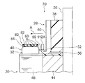
図2に示されるように、整流子28は、シャフト26の周囲に設けられた樹脂製の本体部38と、この本体部38の外周部に設けられた複数の整流子片40とを有している。複数の整流子片40は、それぞれ整流子28の軸方向に延びる板状に形成されており、整流子28の周方向に間隔を空けて配列されている。
As shown in FIG. 2, the
この複数の整流子片40は、導電材料により形成されており、整流子28の外周部(ブラシ摺動面)を形成している。各整流子片40におけるコア30側の端部には、整流子片40の一部がコア30と反対側へ向けて折り曲げられることにより係止爪42が形成されている。この係止爪42は、環状に配列された複数の整流子片40よりも整流子28の径方向外方(矢印A側)に位置されている。また、この係止爪42は、整流子片40におけるコア30側の一部分40Aと整流子28の軸方向にオーバーラップされている。この整流子片40のうち係止爪42とオーバーラップしない部分40Bには、上述のブラシ24(図1参照)が摺接される。
The plurality of
図3に示されるように、コア30は、より具体的には、シャフト26の周囲に形成された環状部44と、この環状部44の周囲に放射状に形成された複数の突起状のティース部46とを有している。複数のティース部46の本数は、一例として、10本とされている。なお、第一実施形態において、図1に示されるマグネット22の磁極数は、4個であり、上述のモータMは、4極10スロットのモータとされている。
As shown in FIG. 3, the core 30 more specifically includes an
図3に示されるように、巻線32は、コア30のうちのティース部46に巻回されている。この巻線32のうちティース部46に巻回された部分は、巻線32の巻回部48である。この巻回部48は、ティース部46に集中巻きで巻回されても良く、また、複数のティース部46に亘って分布巻き(重ね巻き)で巻回されても良い。この巻回部48からは、係止爪42に向けて渡り線50が導出されている。この渡り線50における係止爪42側の端部は、係止爪42との接続部52であり、この接続部52は、係止爪42に引っ掛けられた状態で例えばヒュージング加工により係止爪42に接続されている(図2も参照)。
As shown in FIG. 3, the winding 32 is wound around the
図2に示されるように、コア30の径方向における巻回部48とシャフト26との間には、上述の環状部44の分に相当する隙間54が設けられており、この隙間54には、上述の整流子28が配置されている。整流子28は、後述する如くコア30に近づけて配置されており、このコア30(より具体的には、コア30の表面に設けられたインシュレータ56)に接触されている。この第一実施形態では、一例として、整流子28のうちの係止爪42の基端部が、コア30に接触されている。
As shown in FIG. 2, a
図2,図3に示されるように、第一実施形態に係るアーマチャ10は、本発明における均圧部材の一例として、複数の均圧線60を備えている。この複数の均圧線60及び上述の巻線32は、好ましくは、線材の材料が互いに同一とされる。この場合の巻線32及び複数の均圧線60に使用する線材の材料としては、例えば、銅やアルミニウム等が挙げられる。
As shown in FIGS. 2 and 3, the
図4に示されるように、各均圧線60は、円弧状に形成された周方向配線部64と、この周方向配線部64の両端部から周方向配線部64の径方向内側に延びる径方向配線部66と、この径方向配線部66の先端部に形成された矩形状のフック部68とを有している。
As shown in FIG. 4, each
複数の周方向配線部64は、同心円状に配置される。また、各均圧線60に設けられた一対のフック部68は、各周方向配線部64の径方向に対向して配置され、複数のフック部68は、周方向配線部64の周方向に等間隔で配置される。この複数のフック部68は、上述の複数の係止爪42(図3参照)と同数設けられている。また、各均圧線60は、図3に示されるコア30への組付に伴ってフック部68が係止爪42に引っ掛けられるように予め形状が固定されている(図4に示される形状で保持されている)。つまり、各均圧線60は、予め形状が固定される程度の強度及び剛性を有するように、その線径や材料が選定されている。
The plurality of
そして、図2に示されるように、複数の均圧線60は、整流子28側からコア30に組み付けられている。第一実施形態では、後述するように、コア30及び整流子28がシャフト26に取り付けられ、この状態で巻線32がコア30に巻装される(係止爪42への接続部52の引っ掛けを含む)。そして、その後に、複数の均圧線60は、コア30に組み付けられている。この複数の均圧線60は、コア30に組み付けられた状態においてコア30における整流子28側に配置されている。
As shown in FIG. 2, the plurality of equalizing
また、複数の均圧線60の全体(フック部68を含む)は、整流子28の外周部を形成する複数の整流子片40よりも整流子28の径方向外方(矢印A側)に配置されており、さらに、各均圧線60の周方向配線部64は、整流子片40に設けられた係止爪42よりも整流子28の径方向外方(矢印A側)に配置されている。この複数の周方向配線部64は、コア30の軸方向に巻回部48と重ね合わされている。
Further, the whole of the plurality of equalizing lines 60 (including the hook portion 68) is more radially outward (arrow A side) of the
また、この複数の周方向配線部64は、コア30の径方向に沿って並んで配置されており、それぞれ整流子28の周方向に沿って設けられている(図3も参照)。この複数の周方向配線部64は、その厚み方向の全体が係止爪42における先端側の一部分42Aと整流子28の軸方向にオーバーラップされている。そして、これにより、複数の周方向配線部64は、係止爪42の長さ方向の範囲内(長さL内)に収められている。
The plurality of
また、このように複数の均圧線60がコア30に組み付けられた状態において、各フック部68は、係止爪42に引っ掛けられている。複数の均圧線60は、一例として、巻線32がヒュージング加工により係止爪42に接続される前に、コア30に組み付けられており、各フック部68及び上述の巻線32の接続部52は、ヒュージング加工により同一の整流子片40に同時に接続されている。そして、この各均圧線60により、複数の整流子片40のうち整流子28の径方向に対向する一対の整流子片40(同電位であるべき整流子片40同士)が互いに接続されている(図3参照)。
Further, in a state where the plurality of equalizing
また、第一実施形態では、上述のように、コア30及び整流子28がシャフト26に取り付けられた状態で巻線32がコア30に巻装(係止爪42への接続部52の引っ掛けを含む)された後に、複数の均圧線60がコア30に組み付けられている。このため、均圧線60における係止爪42との接続部であるフック部68は、巻線32における係止爪42との接続部52よりも係止爪42の先端側に位置されている。
In the first embodiment, as described above, the winding 32 is wound around the
続いて、上述のアーマチャ10の製造方法について説明する。
Next, a method for manufacturing the
先ず、図2に示されるコア30及び整流子28がシャフト26に取り付けられる。このとき、整流子28のうち一例として係止爪42の基端部が、コア30(より具体的には、コア30の表面に設けられたインシュレータ56)に接触される。
First, the
そして、コア30及び整流子28がシャフト26に取り付けられた状態で巻線32がコア30に巻装され、ティース部46に巻回部48が形成される。またこのとき、巻線32における係止爪42との接続部52が係止爪42に引っ掛けられる。その後、複数の均圧線60がコア30に組み付けられると共に、各均圧線60のフック部68が巻線32の接続部52の上から係止爪42に引っ掛けられる。このとき、複数の均圧線60は、巻線32の接続部52がヒュージング加工により係止爪42に接続される前に、コア30に組み付けられる。また、この複数の均圧線60は、整流子28側からコア30に組み付けられる。
The winding 32 is wound around the
ここで、各均圧線60は、上述のように予め形状が固定されている。従って、各均圧線60がコア30に組み付けられた場合には、これに伴って、フック部68が係止爪42に引っ掛けられる。また、コア30及び整流子28がシャフト26に取り付けられた状態で巻線32がコア30に巻装された後に、複数の均圧線60がコア30に組み付けられるため、均圧線60における係止爪42との接続部であるフック部68は、巻線32における係止爪42との接続部52よりも係止爪42の先端側に位置される。
Here, the shape of each
そして、巻線32の接続部52及び均圧線60のフック部68がヒュージング加工により同一の整流子片40に同時に接続される。以上の要領により、アーマチャ10は、製造される。
And the
続いて、本発明の第一実施形態の作用及び効果について説明する。 Then, the effect | action and effect of 1st embodiment of this invention are demonstrated.
以上詳述したように、第一実施形態に係るアーマチャ10によれば、整流子28の径方向に対向する一対の整流子片40を接続するために複数の均圧線60が用いられており、各均圧線60の全体(フック部68を含む)は、整流子28の外周部を形成する複数の整流子片40よりも整流子28の径方向外方(矢印A側)に配置されている。従って、例えば複数の均圧線60が整流子28とコア30との軸方向間に配置された場合に比して、整流子28をコア30に近づけて配置することができる。
As described above in detail, according to the
特に、複数の均圧線60は、整流子28の周方向に沿って設けられた周方向配線部64を有し、この各周方向配線部64は、整流子片40に設けられた係止爪42よりも整流子28の径方向外方(矢印A側)に配置されている。従って、周方向配線部64と係止爪42とが整流子28の軸方向に重なり合うことを抑制することができるので、整流子28をコア30により近づけて配置することができる。以上より、アーマチャ10を軸方向に小型化することができる。
In particular, the plurality of equalizing
しかも、整流子28は、コア30に近づけて配置されることでコア30に接触されている。従って、整流子28とコア30との軸方向間の隙間を無くすことができるので、アーマチャ10を軸方向により小型化することができる。
Moreover, the
また、上述のようにアーマチャ10を軸方向に小型化することにより(整流子28をコア30に近づけて配置することにより)、シャフト26の長さや、巻線32として使用する線材の長さを短くすることができる。これにより、材料費を削減することができるので、コストダウンすることができる。
Further, by reducing the size of the
また、コア30及び整流子28がシャフト26に取り付けられた状態で巻線32がコア30に巻装され、その後に、複数の均圧線60がコア30に組み付けられる。従って、コア30に巻線32を巻装する際に、均圧線60が邪魔になることを抑制することができる。これにより、巻線32の巻装時の作業性を確保することができる。
In addition, the winding 32 is wound around the
また、均圧線60は、コア30における整流子28側に配置され、且つ、この均圧線60は、コア30及び整流子28がシャフト26に取り付けられた状態において整流子28側からコア30に組み付けられる。従って、コア30に対して均圧線60が配置される側と、コア30に対して均圧線60が組み付けられる側とが一致するので、均圧線60のコア30への組付作業を容易にすることができる。
The
また、均圧線60は、コア30への組付に伴ってフック部68が係止爪42に引っ掛けられるように予め形状が固定されている。従って、均圧線60をコア30に組み付けることに伴ってフック部68を係止爪42に引っ掛けることができるので、均圧線60の組付時の作業性を向上させることができる。
Further, the shape of the
また、均圧線60は、巻線32がヒュージング加工により係止爪42に接続される前に、コア30に組み付けられる。従って、ヒュージング加工による係止爪42への巻線32の接続と、ヒュージング加工による係止爪42への均圧線60の接続とを同時に行うことができる。これにより、ヒュージング加工の作業効率を向上させることができる。
Further, the equalizing
また、巻線32及び均圧線60は、ヒュージング加工により同一の整流子片40に同時に接続される。従って、巻線32及び均圧線60がヒュージング加工により同一の整流子片40に別々に接続される場合に比して、ヒュージング加工の工数を少なくすることができるので、コストダウンすることができる。
Further, the winding 32 and the equalizing
また、均圧線60の周方向配線部64は、コア30の軸方向に巻回部48と重ね合わされている。従って、巻回部48の巻回スペース(コア30の径方向に沿った巻回スペース)に周方向配線部64が配置されることを抑制することができるので、巻回部48の占積率を確保することができる。
The
また、この周方向配線部64は、その厚み方向の全体が係止爪42における先端側の一部分42Aと整流子28の軸方向にオーバーラップされており、これにより、この周方向配線部64は、係止爪42の長さ方向の範囲内(長さL内)に収められている。従って、周方向配線部64が係止爪42の先端部に対してコア30と反対側へ張り出すことを抑制することができるので、整流子28の軸方向への小型化を図りつつ、整流子28におけるブラシ24(図1参照)との摺接面積を確保することができる。
Further, the
また、複数の周方向配線部64は、コア30の径方向に沿って並んで配置されている。従って、このことによっても、複数の周方向配線部64がコア30と反対側へ張り出すことを抑制することができる。これにより、複数の周方向配線部64がブラシ24(図1参照)と干渉することを抑制することができる。
The plurality of
また、図1に示される第一実施形態に係るモータMによれば、上述のアーマチャ10を備えているので、軸方向の小型化とコストダウンとを両立することができる。
Further, according to the motor M according to the first embodiment shown in FIG. 1, since the
[第二実施形態]
次に、本発明の第二実施形態について説明する。
[Second Embodiment]
Next, a second embodiment of the present invention will be described.
図5,図6に示される本発明の第二実施形態に係るアーマチャ70は、上述の第一実施形態に係るアーマチャ10(図2,図3参照)に対し、次のように構成が変更されている。
The
すなわち、本発明の第二実施形態に係るアーマチャ70は、整流子28の径方向に対向する一対の整流子片40(同電位であるべき整流子片40同士)を互いに接続するために、均圧部材80を備えている。
That is, the
均圧部材80は、上述の第一実施形態における複数の均圧線60に加え、これら複数の均圧線60を保持するモールド樹脂82を有している。このモールド樹脂82は、保持部材の一例であり、モールド成形により複数の均圧線60と一体化されている。このモールド樹脂82は、より具体的には、複数の均圧線60のうち周方向配線部64を覆っており、均圧線60のうちの径方向配線部66とフック部68とは、モールド樹脂82からモールド樹脂82の径方向内側に突出している。
The
この複数の均圧線60及びモールド樹脂82を有する均圧部材80の全体(フック部68を含む)は、整流子28の外周部を形成する複数の整流子片40よりも整流子28の径方向外方(矢印A側)に配置されている。図6に示されるように、モールド樹脂82は、整流子28の周方向に沿って円環状に設けられている。
The entire
複数の均圧線60のうちモールド樹脂82に覆われた部分(周方向配線部64)と、モールド樹脂82とは、均圧部材80における周方向配線部84を形成している。この周方向配線部84は、整流子28の周方向に沿って設けられると共に、係止爪42よりも整流子28の径方向外方(矢印A側)に配置されている。また、この周方向配線部84は、コア30の軸方向に巻回部48と重ね合わされている。
Of the plurality of
さらに、この周方向配線部84は、その厚み方向の全体が係止爪42における先端側の一部分42Aと整流子28の軸方向にオーバーラップされている。そして、これにより、周方向配線部84は、係止爪42の長さ方向の範囲内(長さL内)に収められている。
Further, the
また、均圧部材80は、複数の均圧線60がモールド樹脂82により一体化されることにより、コア30への組付に伴ってフック部68が係止爪42に引っ掛けられるように予め形状が固定されている。つまり、均圧部材80は、予め形状が固定される程度の強度及び剛性を有するように、均圧線60の線径や材料、及び、モールド樹脂82の形状や寸法が選定されている。
Further, the
そして、この均圧部材80は、上述の第一実施形態における複数の均圧線60と同様に、コア30及び整流子28がシャフト26に取り付けられた状態で巻線32がコア30に巻装された後で且つ巻線32がヒュージング加工により係止爪42に接続される前に、整流子28側からコア30に組み付けられる。
The
なお、本発明の第二実施形態において、上記以外の構成は、上述の第一実施形態と同様である。また、本発明の第二実施形態において、上述の第一実施形態と同一の構成については、同一の符号を用い、その説明を省略する。 In the second embodiment of the present invention, configurations other than those described above are the same as those in the first embodiment described above. Moreover, in 2nd embodiment of this invention, about the structure same as the above-mentioned 1st embodiment, the same code | symbol is used and the description is abbreviate | omitted.
続いて、本発明の第二実施形態の作用及び効果について説明する。 Then, the effect | action and effect of 2nd embodiment of this invention are demonstrated.
以上詳述したように、第二実施形態に係るアーマチャ70によれば、整流子28の径方向に対向する一対の整流子片40を接続するために均圧部材80が用いられており、この均圧部材80の全体(フック部68を含む)は、整流子28の外周部を形成する複数の整流子片40よりも整流子28の径方向外方(矢印A側)に配置されている。従って、例えば均圧部材80が整流子28とコア30との軸方向間に配置された場合に比して、整流子28をコア30に近づけて配置することができる。
As described above in detail, according to the
特に、均圧部材80は、整流子28の周方向に沿って設けられた周方向配線部84を有し、この周方向配線部84は、整流子片40に設けられた係止爪42よりも整流子28の径方向外方(矢印A側)に配置されている。従って、周方向配線部84と係止爪42とが整流子28の軸方向に重なり合うことを抑制することができるので、整流子28をコア30により近づけて配置することができる。以上より、アーマチャ10を軸方向に小型化することができる。
In particular, the
しかも、整流子28は、コア30に近づけて配置されることでコア30に接触されている。従って、整流子28とコア30との軸方向間の隙間を無くすことができるので、アーマチャ10を軸方向により小型化することができる。
Moreover, the
また、上述のようにアーマチャ10を軸方向に小型化することにより(整流子28をコア30に近づけて配置することにより)、シャフト26の長さや、巻線32として使用する線材の長さを短くすることができる。これにより、材料費を削減することができるので、コストダウンすることができる。
Further, by reducing the size of the
また、コア30及び整流子28がシャフト26に取り付けられた状態で巻線32がコア30に巻装され、その後に、均圧部材80がコア30に組み付けられる。従って、コア30に巻線32を巻装する際に、均圧部材80が邪魔になることを抑制することができる。これにより、巻線32の巻装時の作業性を確保することができる。
The winding 32 is wound around the
また、均圧部材80は、コア30における整流子28側に配置され、且つ、この均圧部材80は、コア30及び整流子28がシャフト26に取り付けられた状態において整流子28側からコア30に組み付けられる。従って、コア30に対して均圧部材80が配置される側と、コア30に対して均圧部材80が組み付けられる側とが一致するので、均圧部材80のコア30への組付作業を容易にすることができる。
The
また、均圧部材80は、コア30への組付に伴ってフック部68が係止爪42に引っ掛けられるように予め形状が固定されている。従って、均圧部材80をコア30に組み付けることに伴ってフック部68を係止爪42に引っ掛けることができるので、均圧部材80の組付時の作業性を向上させることができる。
Further, the shape of the
特に、この均圧部材80に設けられたモールド樹脂82により、複数の均圧線60が一体化されているので、複数の均圧線60がばらけることを抑制することができ、この複数の均圧線60を一斉にコア30に組み付けることができる。これにより、組付工数の増加を抑制することができる。
In particular, since the plurality of
また、均圧部材80は、巻線32がヒュージング加工により係止爪42に接続される前に、コア30に組み付けられる。従って、ヒュージング加工による係止爪42への巻線32の接続と、ヒュージング加工による係止爪42への均圧部材80の接続とを同時に行うことができる。これにより、ヒュージング加工の作業効率を向上させることができる。
The
また、巻線32及び均圧部材80は、ヒュージング加工により同一の整流子片40に同時に接続される。従って、巻線32及び均圧部材80がヒュージング加工により同一の整流子片40に別々に接続される場合に比して、ヒュージング加工の工数を少なくすることができるので、コストダウンすることができる。
The winding 32 and the
また、均圧部材80の周方向配線部84は、コア30の軸方向に巻回部48と重ね合わされている。従って、巻回部48の巻回スペース(コア30の径方向に沿った巻回スペース)に周方向配線部84が配置されることを抑制することができるので、巻回部48の占積率を確保することができる。
Further, the
また、この周方向配線部84は、その厚み方向の全体が係止爪42における先端側の一部分42Aと整流子28の軸方向にオーバーラップされており、これにより、この周方向配線部84は、係止爪42の長さ方向の範囲内(長さL内)に収められている。従って、周方向配線部84が係止爪42の先端部に対してコア30と反対側へ張り出すことを抑制することができるので、整流子28の軸方向への小型化を図りつつ、整流子28におけるブラシ24(図1参照)との摺接面積を確保することができる。
Further, the
また、均圧部材80において、均圧線60に形成された複数の周方向配線部64は、コア30の径方向に沿って並んで配置されている。従って、この複数の周方向配線部64及びモールド樹脂82からなる均圧部材80の周方向配線部84の厚さを抑えることができる。これにより、この均圧部材80の周方向配線部84がコア30と反対側へ張り出すことを抑制することができるので、この周方向配線部84がブラシ24(図1参照)と干渉することを抑制することができる。
In the
次に、上記第一、第二実施形態に共通の変形例について説明する。 Next, a modification common to the first and second embodiments will be described.
[第一変形例]
上記第一、第二実施形態においては、図8に示されるように、複数のティース部46の本数は、24本とされていても良い。また、特に図示しないが、複数のティース部46の本数は、上記以外でも良い。さらに、図1に示されるマグネット22の磁極数も上記以外でも良い。
[First modification]
In the first and second embodiments, as shown in FIG. 8, the number of the plurality of
[第二変形例]
上記第二実施形態において、均圧線60に形成された複数の周方向配線部64は、コア30の径方向に沿って並んで配置されていたが、図9に示されるように、複数の周方向配線部64は、コア30の径方向及び軸方向に沿って並んで配置されていても良い。また、この場合に、複数の周方向配線部64及びモールド樹脂82からなる均圧部材80の周方向配線部84の厚み方向の一部(コア30側の一部分)のみが、係止爪42における先端側の一部分42Aと整流子28の軸方向にオーバーラップされていても良い。
[Second modification]
In the second embodiment, the plurality of
このように構成されていても、周方向配線部84が係止爪42の先端部に対してコア30と反対側へ張り出すことを抑制することができるので、整流子28の軸方向への小型化を図りつつ、整流子28におけるブラシ24(図1参照)との摺接面積を確保することができる。
Even if configured in this way, the
なお、特に図示しないが、上記第一実施形態において、複数の周方向配線部64が、コア30の径方向及び軸方向に沿って並んで配置されていても良い。また、この場合に、複数の周方向配線部64の厚み方向の一部が、係止爪42における先端側の一部分42Aと整流子28の軸方向にオーバーラップされていても良い。
Although not particularly illustrated, in the first embodiment, the plurality of
[第三変形例]
上記第二実施形態においては、図10に示されるように、例えば、コア30(インシュレータ56)における巻回部48よりも径方向外側の部分に平坦面からなる位置決め部90が設けられ、均圧部材80には、モールド樹脂82の外周部から位置決め部90に向けて延びる被位置決め部92が設けられても良い。そして、被位置決め部92が位置決め部90に当接されることにより、均圧部材80がコア30に対してコア30の軸方向及び径方向に位置決めされても良い。
[Third modification]
In the second embodiment, as shown in FIG. 10, for example, a
このように構成されていると、均圧部材80をコア30に対して位置決めすることができるので、均圧部材80のコア30への組付性を良好にすることができる。また、均圧部材80を整流子28に対しても位置決めすることができるので、均圧部材80の組付時にフック部68を係止爪42に容易に引っ掛けることができる。
If comprised in this way, since the
なお、上述の位置決め部90及び被位置決め部92は、コア30及び均圧部材80のどの部分に形成されても良い。
The positioning
また、特に図示しないが、上記第一実施形態における均圧線60についても、位置決め部90と接触して均圧線60を位置決めする被位置決め部が設けられても良い。
In addition, although not particularly illustrated, a positioned portion that positions the
[第四変形例]
上記第二実施形態においては、図11に示されるように、例えば、コア30(インシュレータ56)における巻回部48よりも径方向外側の部分に爪状の嵌合部94が設けられ、均圧部材80には、モールド樹脂82の外周部から嵌合部94に向けて延びる爪状の被嵌合部96が設けられても良い。そして、被嵌合部96が嵌合部94に嵌合されることにより、均圧部材80がコア30に対して固定されても良い。
[Fourth modification]
In the second embodiment, as shown in FIG. 11, for example, a claw-like
このように構成されていると、均圧部材80をコア30に対して固定することができるので、均圧部材80のコア30に対するがたつきを抑制することができる。
If comprised in this way, since the
なお、上述の嵌合部94及び被嵌合部96は、コア30及び均圧部材80のどの部分に形成されても良い。
The
また、特に図示しないが、上記第一実施形態における均圧線60についても、嵌合部94と嵌合されて均圧線60をコア30に対して固定する被嵌合部が設けられても良い。
Although not particularly illustrated, the
[第五変形例]
上記第二実施形態においては、図12に示されるように、例えば、整流子28(本体部38)におけるコア30側の端部に整流子28の径方向外側に延びる位置決め部100が設けられ、均圧部材80には、モールド樹脂82の内周部からコア30側に向けて延びる被位置決め部102が設けられても良い。そして、被位置決め部102が位置決め部100に当接されることにより、均圧部材80が整流子28に対して整流子28の径方向に位置決めされても良い。
[Fifth Modification]
In the second embodiment, as shown in FIG. 12, for example, a
このように構成されていると、均圧部材80を整流子28に対して位置決めすることができるので、均圧部材80の組付時にフック部68を係止爪42に容易に引っ掛けることができる。また、均圧部材80をコア30に対しても位置決めすることができるので、均圧部材80のコア30への組付性を良好にすることができる。
With this configuration, the
なお、上述の位置決め部100及び被位置決め部102は、コア30及び均圧部材80のどの部分に形成されても良い。
The
また、第五変形例と上述の第三変形例とが組み合わされることにより、コア30及び整流子28の両方に位置決め部が形成されると共に、この各位置決め部に対応する被位置決め部が均圧部材80に形成されても良い。
Further, by combining the fifth modified example and the above-described third modified example, positioning portions are formed in both the
また、特に図示しないが、上記第一実施形態における均圧線60についても、位置決め部100と接触して均圧線60を位置決めする被位置決め部が設けられても良い。
Further, although not particularly illustrated, a positioned portion that positions the
[第六変形例]
上記第二実施形態においては、図13に示されるように、例えば、整流子28(本体部38)におけるコア30側の端部に整流子28の径方向外側に延びる嵌合部104が設けられ、均圧部材80には、モールド樹脂82の内周部からコア30側に向けて延びる被嵌合部106が設けられても良い。そして、被嵌合部106が嵌合部104に嵌合されることにより、均圧部材80が整流子28に対して固定されても良い。
[Sixth Modification]
In the second embodiment, as shown in FIG. 13, for example, a
このように構成されていると、均圧部材80を整流子28に対して固定することができるので、均圧部材80の整流子28に対するがたつきを抑制することができる。
If comprised in this way, since the
なお、上述の嵌合部104及び被嵌合部106は、整流子28及び均圧部材80のどの部分に形成されても良い。
The
また、第六変形例と上述の第四変形例とが組み合わされることにより、コア30及び整流子28の両方に嵌合部が形成されると共に、この各嵌合部に対応する被嵌合部が均圧部材80に形成されても良い。
Further, by combining the sixth modified example and the above-described fourth modified example, fitting parts are formed in both the
また、特に図示しないが、上記第一実施形態における均圧線60についても、嵌合部104と嵌合されて均圧線60を整流子28に対して固定する被嵌合部が設けられても良い。
Although not particularly illustrated, the
[第七変形例]
上記第二実施形態においては、例えば、次の要領でアーマチャ10が製造されても良い。つまり、第七変形例では、図14の上図に示されるように、先ず、コア30及び整流子28がシャフト26に取り付けられる。このとき、整流子28は、巻線32及び均圧部材80よりもコア30と反対側に移動された状態とされる。
[Seventh modification]
In the second embodiment, for example, the
そして、この状態で巻線32がコア30に巻装され、ティース部46に巻回部48が形成される。また、巻線32における係止爪42との接続部52が係止爪42に引っ掛けられる。その後、均圧部材80がコア30に組み付けられる。このとき、均圧部材80は、整流子28側からコア30に組み付けられる。また、均圧部材80は、巻線32がヒュージング加工により係止爪42に接続される前に、コア30に組み付けられる。
In this state, the winding 32 is wound around the
そして、巻線32の接続部52の上から均圧部材80のフック部68が係止爪42に引っ掛けられる。この均圧部材80は、予め形状が固定されているため、均圧部材80がコア30に組み付けられた場合には、これに伴って、フック部68が係止爪42に引っ掛けられる。また、巻線32の接続部52及び均圧部材80のフック部68がヒュージング加工により同一の整流子片40に同時に接続される。
Then, the
そして、このようにして巻線32及び均圧部材80が整流子片40に接続された後に、図14の下図に示されるように、整流子28がコア30側に移動される。このとき、整流子28のうち一例として係止爪42の基端部が、コア30(より具体的には、コア30の表面に設けられたインシュレータ56)に接触される。以上の要領により、アーマチャ10は、製造される。
Then, after the winding 32 and the
このように、第七変形例では、整流子28が巻線32及び均圧部材80よりもコア30と反対側に移動された状態で、巻線32の接続部52及び均圧部材80のフック部68が係止爪42に接続されるので、接続部52及びフック部68を係止爪42に接続する際(ヒュージング加工する際)に、巻回部48や周方向配線部84が邪魔になることを抑制することができる。これにより、接続部52及びフック部68を係止爪42に接続する際の作業性を向上させることができる。
As described above, in the seventh modification, the
なお、特に図示しないが、上記第一実施形態においても、整流子28が巻線32及び均圧線60よりもコア30と反対側に移動された状態で、この巻線32及び均圧線60が整流子片40に接続されても良い。また、このようにして巻線32及び均圧線60が整流子片40に接続された後に、整流子28がコア30側に移動されても良い。
Although not particularly shown, in the first embodiment, the
[第八変形例]
上記第二実施形態においては、図15,図16に示されるように、各整流子片40には、第一係止爪112A及び第二係止爪112Bが折り曲げられて形成され、巻線32の接続部52は、第一係止爪112Aに接続され、均圧部材80のフック部68は、第二係止爪112Bに接続されても良い。
[Eighth Modification]
In the second embodiment, as shown in FIGS. 15 and 16, each
このように、巻線32の接続部52と均圧部材80のフック部68とが互いに異なる第一係止爪112A及び第二係止爪112Bに接続される構成とされていると、接続部52及びフック部68の整流子片40への接続時(係止爪への引っ掛け時)の作業性を良好にすることができる。
Thus, when the
なお、特に図示しないが、上記第一実施形態においても、各整流子片40に、第一係止爪112A及び第二係止爪112Bが折り曲げられて形成され、巻線32の接続部52は、第一係止爪112Aに接続され、均圧線60のフック部68は、第二係止爪112Bに接続されても良い。
Although not particularly illustrated, also in the first embodiment, each
また、整流子28には、巻線32の接続部52のみが接続される係止爪と、均圧線60のフック部68のみが接続される係止爪と、巻線32の接続部52及び均圧線60のフック部68の両方が接続される係止爪が混在して設けられていても良い。
Also, the
[第九変形例]
上記第二実施形態における均圧部材80の配置は、図17に示されるように変更されても良い。つまり、この第九変形例において、均圧部材80の周方向配線部84は、コア30の径方向における整流子28と巻回部48との間に配置されている。また、周方向配線部84は、コア30に対する巻回部48の突出高さの範囲内に収まるように、その厚みが薄く抑えられており、さらに、この周方向配線部84は、その厚み方向の全体が係止爪42における基端側の一部分42Bと整流子28の軸方向にオーバーラップされている。
[Ninth Modification]
The arrangement of the
また、この均圧部材80は、コア30及び整流子28がシャフト26に取り付けられた状態で巻線32がコア30に巻装される前に、コア30に組み付けられており、均圧部材80における係止爪42との接続部52であるフック部68は、巻線32における係止爪42との接続部52よりも係止爪42の基端側に位置されている。さらに、巻線32における係止爪42との接続部52と巻回部48との間に設けられた渡り線50は、均圧部材80よりもコア30と反対側に離間して配置されている。
The
この第九変形例によれば、コア30及び整流子28がシャフト26に取り付けられ、この状態で巻線32がコア30に巻装される前に、均圧部材80は、コア30に組み付けられる。従って、均圧部材80をコア30に組み付ける際に、巻線32が邪魔になることを抑制することができる。これにより、均圧部材80の組付時の作業性を確保することができる。
According to the ninth modification, the
また、均圧部材80の周方向配線部84は、コア30の径方向における整流子28と巻回部48との間に配置されている。従って、コア30の径方向における整流子28と巻回部48との間に残ったスペースを周方向配線部84の配置のために有効に利用することができるので、アーマチャ10を軸方向及び径方向に小型化することができる。
Further, the
また、均圧部材80の周方向配線部84は、コア30に対する巻回部48の突出高さの範囲内に収められている。従って、均圧部材80の周方向配線部84が巻回部48よりもコア30の軸方向に突出することを抑制することができるので、整流子28の軸方向への小型化を図りつつ、整流子28におけるブラシ24(図1参照)との摺接面積を確保することができる。
Further, the
また、巻線32における係止爪42との接続部52と巻回部48との間に設けられた渡り線50は、均圧部材80よりもコア30と反対側に離間して配置されている。従って、渡り線50を配線する際に、均圧部材80が邪魔になることを抑制することができるので、渡り線50の配線時の作業性も確保することができる。
Further, the connecting
なお、特に図示しないが、上記第一実施形態においても、上記第九変形例が適用されても良い。つまり、上記第九変形例において、モールド樹脂82が省かれることにより、第一実施形態に上記第九変形例が適用された構成とされても良い。
Although not particularly illustrated, the ninth modification may be applied also in the first embodiment. In other words, in the ninth modified example, the ninth modified example may be applied to the first embodiment by omitting the
[その他の変形例]
上記第一、第二実施形態において、巻線32は、いずれか一対の整流子片40を接続する均圧線60を上述の複数の均圧線60とは別に含んでいても良い。また、この場合に、巻線32に含まれる均圧線60は、整流子28及びコア30の軸方向間に配置されても良い。
[Other variations]
In the first and second embodiments, the winding 32 may include a
また、上記第一、第二実施形態において、複数の均圧線60は、同電位であるべき整流子片40同士の一例として、整流子28の径方向に対向する一対の整流子片40を接続していたが、複数の均圧線60は、整流子28の径方向に対向する一対の整流子片40以外の整流子片40同士を接続していても良い。
In the first and second embodiments, the plurality of
また、上記第一、第二実施形態においては、同電位であるべき整流子片40同士を接続するために、均圧部材の一例として、線材である均圧線60が用いられていたが、線材以外の部材(例えば、ターミナルなどの細長の板材)により形成された均圧部材が用いられても良い。
In the first and second embodiments, in order to connect the
また、上記第一、第二実施形態において、整流子28は、係止爪42にてコア30に接触されていたが、この係止爪42の代わりに、例えば、整流子片40や本体部38など、整流子28における係止爪42以外の部分がコア30に接触されていても良い。また、整流子28は、コア30に接触されずに近接されても良い。
In the first and second embodiments, the
また、上記第一実施形態では、周方向配線部64の厚み方向の少なくとも一部が、係止爪42における少なくとも長さ方向の一部分と整流子28の軸方向にオーバーラップされるように、各部の寸法や配置が変更されても良い。同様に、上記第二実施形態では、周方向配線部84の厚み方向の少なくとも一部が、係止爪42における少なくとも長さ方向の一部分と整流子28の軸方向にオーバーラップされるように、各部の寸法や配置が変更されても良い。
In the first embodiment, each part is arranged such that at least a part in the thickness direction of the
また、上記第一、第二実施形態において、均圧線60及び巻線32は、好ましい例として、線材の材料が互いに同一とされていたが、線材の材料が互いに異なっていても良い。この巻線32及び均圧線60に使用する線材の材料としては、例えば、銅やアルミニウム等が挙げられる。また、均圧線60及び巻線32は、線材の線径が同一でも良く、また、線材の線径が互いに異なっていても良い。
In the first and second embodiments, the
また、上記第一、第二実施形態において、各フック部68及び上述の巻線32の接続部52は、ヒュージング加工により同一の整流子片40に順次接続されても良い。このようにヒュージング加工による係止爪42への巻線32の接続と均圧線60の接続とを連続して行うことにより、ヒュージング加工の作業効率を向上させることができる。
In the first and second embodiments, each
なお、上記複数の変形例のうち組み合わせ可能な変形例は、適宜組み合わされて実施可能であることは勿論である。 Of course, the combinations that can be combined among the plurality of modifications can be implemented by appropriately combining them.
以上、本発明の一態様について説明したが、本発明は、上記に限定されるものでなく、上記以外にも、その主旨を逸脱しない範囲内において種々変形して実施可能であることは勿論である。 Although one embodiment of the present invention has been described above, the present invention is not limited to the above, and it is needless to say that various modifications can be made without departing from the spirit of the present invention. is there.
10,70…アーマチャ、12…固定子、14…フロントハウジング、16…エンドハウジング、18…ブラシ装置、20…ヨーク、22…マグネット、24…ブラシ、26…シャフト、28…整流子、30…コア、32…巻線、34,36…軸受、38…本体部、40…整流子片、42…係止爪、44…環状部、46…ティース部、48…巻回部、50…渡り線、52…接続部、54…隙間、56…インシュレータ、60…均圧線(均圧部材の一例)、64…周方向配線部、66…径方向配線部、68…フック部、80…均圧部材、82…モールド樹脂、84…周方向配線部、90,100…位置決め部、92,102…被位置決め部、94,104…嵌合部、96,106…被嵌合部、112A…第一係止爪、112B…第二係止爪、M…モータ
DESCRIPTION OF
Claims (12)
前記シャフトに取り付けられたコアと、
前記シャフトの周囲に設けられた本体部と、前記本体部の外周部に設けられた複数の整流子片と、各前記整流子片における前記コア側の端部に形成され前記コアと反対側へ向けて折り曲げられた複数の係止爪とを有する整流子と、
前記コアに巻装されると共に、前記係止爪に接続された巻線と、
前記複数の整流子片のうちいずれか一対の整流子片に形成された前記係止爪同士を接続する均圧部材と、
を備え、
前記均圧部材は、
前記整流子の周方向に沿って設けられた複数の周方向配線部と、
各前記周方向配線部の両端部から前記周方向配線部の径方向内側に延びる複数の径方向配線部と、
前記複数の周方向配線部と一体化された保持部材と、
を有し、
前記複数の周方向配線部及び前記保持部材により一体化された部分は、前記径方向配線部を介して前記係止爪よりも前記整流子の径方向外方に配置されると共に、その少なくとも軸方向の一部が前記係止爪と前記整流子の軸方向にオーバーラップする、
アーマチャ。 A shaft,
A core attached to the shaft;
A main body provided around the shaft , a plurality of commutator pieces provided on the outer periphery of the main body, and formed on an end of the commutator piece on the core side to the opposite side of the core. A commutator having a plurality of locking claws bent toward the
Winding wound around the core and connected to the locking claw ;
A pressure equalizing member that connects the locking claws formed on any one of the plurality of commutator pieces ;
With
The pressure equalizing member is
A plurality of circumferential wiring portions provided along the circumferential direction of the commutator;
A plurality of radial wiring portions extending radially inward of the circumferential wiring portion from both ends of each circumferential wiring portion;
A holding member integrated with the plurality of circumferential wiring portions;
Have
The portion integrated by the plurality of circumferential wiring portions and the holding member is disposed radially outward of the commutator with respect to the locking claw via the radial wiring portion, and at least a shaft thereof. A part of the direction overlaps the axial direction of the locking claw and the commutator,
Armature.
請求項1に記載のアーマチャ。 The pressure equalizing member is assembled to the core after the winding is wound around the core in a state where the core and the commutator are attached to the shaft.
The armature according to claim 1.
請求項1に記載のアーマチャ。 The pressure equalizing member is assembled to the core before the winding is wound around the core in a state where the core and the commutator are attached to the shaft.
The armature according to claim 1.
請求項1〜請求項3のいずれか一項に記載のアーマチャ。 The pressure equalizing member is disposed on the commutator side of the core, and the pressure equalizing member is assembled to the core from the commutator side in a state where the core and the commutator are attached to the shaft. ing,
The armature as described in any one of Claims 1-3.
請求項2〜請求項4のいずれか一項に記載のアーマチャ。 The pressure equalizing member is assembled to the core before the winding is connected to the locking claw by fusing.
The armature according to any one of claims 2 to 4.
前記均圧部材は、前記コアへの組付に伴って前記フック部が前記係止爪に引っ掛けられるように予め形状が固定されている、
請求項2〜請求項5のいずれか一項に記載のアーマチャ。 The pressure equalizing member is formed with a hook portion that is hooked on the locking claw,
The shape of the pressure equalizing member is fixed in advance so that the hook portion is hooked on the locking claw with the assembly to the core.
The armature according to any one of claims 2 to 5.
請求項1〜請求項6のいずれか一項に記載のアーマチャ。 The commutator is in contact with or close to the core;
The armature as described in any one of Claims 1-6.
前記複数の周方向配線部及び前記保持部材により一体化された部分は、前記コアの軸方向に前記巻回部と重ね合わされている、
請求項2に記載のアーマチャ。 The winding has a winding part wound around a tooth part formed in the core,
The portions integrated by the plurality of circumferential wiring portions and the holding member are overlapped with the winding portion in the axial direction of the core,
The armature according to claim 2 .
前記複数の周方向配線部及び前記保持部材により一体化された部分は、前記コアの径方向における前記整流子と前記巻回部との間に配置されている、
請求項3に記載のアーマチャ。 The winding has a winding part wound around a tooth part formed in the core,
The portion integrated by the plurality of circumferential wiring portions and the holding member is disposed between the commutator and the winding portion in the radial direction of the core.
The armature according to claim 3 .
請求項9に記載のアーマチャ。 The portion integrated by the plurality of circumferential wiring portions and the holding member is housed within a range of the protruding height of the winding portion with respect to the core.
The armature according to claim 9 .
請求項9又は請求項10に記載のアーマチャ。 The connecting wire provided between the connection portion of the winding with the locking claw and the winding portion is disposed away from the pressure equalizing member on the side opposite to the core.
The armature according to claim 9 or 10 .
Priority Applications (4)
| Application Number | Priority Date | Filing Date | Title |
|---|---|---|---|
| JP2013255346A JP6205260B2 (en) | 2013-12-10 | 2013-12-10 | Armature and motor |
| US14/559,936 US10128708B2 (en) | 2013-12-10 | 2014-12-04 | Armature and motor |
| DE102014225125.7A DE102014225125A1 (en) | 2013-12-10 | 2014-12-08 | Anchor and engine |
| CN201410749284.4A CN104702074B (en) | 2013-12-10 | 2014-12-09 | Armature and motor |
Applications Claiming Priority (1)
| Application Number | Priority Date | Filing Date | Title |
|---|---|---|---|
| JP2013255346A JP6205260B2 (en) | 2013-12-10 | 2013-12-10 | Armature and motor |
Publications (2)
| Publication Number | Publication Date |
|---|---|
| JP2015116015A JP2015116015A (en) | 2015-06-22 |
| JP6205260B2 true JP6205260B2 (en) | 2017-09-27 |
Family
ID=53185586
Family Applications (1)
| Application Number | Title | Priority Date | Filing Date |
|---|---|---|---|
| JP2013255346A Expired - Fee Related JP6205260B2 (en) | 2013-12-10 | 2013-12-10 | Armature and motor |
Country Status (4)
| Country | Link |
|---|---|
| US (1) | US10128708B2 (en) |
| JP (1) | JP6205260B2 (en) |
| CN (1) | CN104702074B (en) |
| DE (1) | DE102014225125A1 (en) |
Families Citing this family (3)
| Publication number | Priority date | Publication date | Assignee | Title |
|---|---|---|---|---|
| EP2980971B1 (en) * | 2013-03-26 | 2020-04-22 | Mitsuba Corporation | Electric motor |
| KR101786671B1 (en) * | 2015-12-02 | 2017-10-18 | 현대자동차 주식회사 | Rotor structure of wrsm motor |
| JP6615314B2 (en) * | 2016-03-18 | 2019-12-04 | 三菱電機株式会社 | In-vehicle brushed motor and manufacturing method thereof |
Family Cites Families (16)
| Publication number | Priority date | Publication date | Assignee | Title |
|---|---|---|---|---|
| JP3559178B2 (en) | 1998-10-23 | 2004-08-25 | 三菱電機株式会社 | Rotating electric machine and method of manufacturing the same |
| JP2002186210A (en) * | 2000-12-12 | 2002-06-28 | Mitsuba Corp | Dynamo-electric machine and manufacturing method therefor |
| JP2003169458A (en) * | 2001-12-04 | 2003-06-13 | Mitsuba Corp | Wiring structure for equalizing wire in rotating electric machine |
| US6903483B2 (en) * | 2002-08-27 | 2005-06-07 | Asmo, Co., Ltd. | Motor |
| JP2004088916A (en) * | 2002-08-27 | 2004-03-18 | Asmo Co Ltd | Motor |
| WO2005034315A1 (en) | 2003-10-06 | 2005-04-14 | Asmo Co., Ltd. | Short-circuiting member, commutator, and method of manufacturing short-circuiting member |
| DE102006033432A1 (en) * | 2005-07-19 | 2007-02-08 | Asmo Co., Ltd., Kosai | Method and device for producing a short-circuit part and a method for producing a commutator |
| US7777390B2 (en) * | 2007-04-03 | 2010-08-17 | Asmo Co., Ltd | Short-circuit member assembly, commutator, and motor |
| JP5009181B2 (en) * | 2007-05-11 | 2012-08-22 | アスモ株式会社 | Short-circuit member, commutator, armature, and method for manufacturing short-circuit member |
| JP2009183114A (en) * | 2008-01-31 | 2009-08-13 | Mitsuba Corp | Electric motor |
| JP2009303389A (en) * | 2008-06-13 | 2009-12-24 | Mitsuba Corp | Motor with brush |
| USRE45912E1 (en) | 2008-06-30 | 2016-03-01 | Mitsuba Corporation | Electric motor |
| JP2011041389A (en) * | 2009-08-10 | 2011-02-24 | Mitsuba Corp | Three-phase direct-current motor |
| JP2011200093A (en) * | 2010-02-26 | 2011-10-06 | Minebea Co Ltd | Motor with dc brush |
| JP5671815B2 (en) | 2010-03-04 | 2015-02-18 | アイシン精機株式会社 | DC motor armature |
| JP5738084B2 (en) * | 2011-06-16 | 2015-06-17 | 三菱電機株式会社 | Commutator, rotor provided with commutator, and method of manufacturing rotor provided with commutator |
-
2013
- 2013-12-10 JP JP2013255346A patent/JP6205260B2/en not_active Expired - Fee Related
-
2014
- 2014-12-04 US US14/559,936 patent/US10128708B2/en not_active Expired - Fee Related
- 2014-12-08 DE DE102014225125.7A patent/DE102014225125A1/en not_active Withdrawn
- 2014-12-09 CN CN201410749284.4A patent/CN104702074B/en not_active Expired - Fee Related
Also Published As
| Publication number | Publication date |
|---|---|
| CN104702074A (en) | 2015-06-10 |
| JP2015116015A (en) | 2015-06-22 |
| CN104702074B (en) | 2019-09-24 |
| DE102014225125A1 (en) | 2015-06-11 |
| US10128708B2 (en) | 2018-11-13 |
| US20150162794A1 (en) | 2015-06-11 |
Similar Documents
| Publication | Publication Date | Title |
|---|---|---|
| JP6247595B2 (en) | Armature, armature manufacturing method, rotating electric machine, rotating electric machine manufacturing method | |
| JP4270307B2 (en) | Crossover module | |
| JP2012110212A (en) | Stator, brushless motor and method of manufacturing stator | |
| JP6058164B2 (en) | Rotating electric machine | |
| JP4636192B2 (en) | Bus ring and its mounting structure | |
| JP5502115B2 (en) | Stator, brushless motor, and stator manufacturing method | |
| JP6091058B2 (en) | Electric motor | |
| JP6205260B2 (en) | Armature and motor | |
| JP2020025463A (en) | Brushless motor | |
| JP2009183045A (en) | Method of manufacturing brush holder, brush holder, and electric motor | |
| JP2013223414A (en) | Stator | |
| JP6337132B2 (en) | Rotating electric machine stator and rotating electric machine equipped with the same | |
| WO2021230058A1 (en) | Motor | |
| JP2019135903A (en) | Armature of rotary electric machine and rotary electric machine | |
| US9825498B2 (en) | Armature and armature manufacturing method | |
| KR102485024B1 (en) | Stator and motor including the same | |
| JP6080964B2 (en) | Rotating electric machine stator | |
| WO2017077632A1 (en) | Rotor of rotating electric machine | |
| JP5910363B2 (en) | Rotating electric machine stator | |
| JP6413844B2 (en) | Commutator, motor, commutator manufacturing method | |
| JP6579967B2 (en) | motor | |
| JP2016052229A (en) | Resolver for motor and method for mounting to the motor | |
| JP6514978B2 (en) | Stator, motor and method of manufacturing stator | |
| JP6308002B2 (en) | Rotating electrical machine rotor | |
| JP2013021834A (en) | Rotary electric machine and method for manufacturing the same |
Legal Events
| Date | Code | Title | Description |
|---|---|---|---|
| A621 | Written request for application examination |
Free format text: JAPANESE INTERMEDIATE CODE: A621 Effective date: 20160425 |
|
| A131 | Notification of reasons for refusal |
Free format text: JAPANESE INTERMEDIATE CODE: A131 Effective date: 20170328 |
|
| A977 | Report on retrieval |
Free format text: JAPANESE INTERMEDIATE CODE: A971007 Effective date: 20170331 |
|
| A521 | Request for written amendment filed |
Free format text: JAPANESE INTERMEDIATE CODE: A523 Effective date: 20170510 |
|
| TRDD | Decision of grant or rejection written | ||
| A01 | Written decision to grant a patent or to grant a registration (utility model) |
Free format text: JAPANESE INTERMEDIATE CODE: A01 Effective date: 20170822 |
|
| A61 | First payment of annual fees (during grant procedure) |
Free format text: JAPANESE INTERMEDIATE CODE: A61 Effective date: 20170904 |
|
| R150 | Certificate of patent or registration of utility model |
Ref document number: 6205260 Country of ref document: JP Free format text: JAPANESE INTERMEDIATE CODE: R150 |
|
| S111 | Request for change of ownership or part of ownership |
Free format text: JAPANESE INTERMEDIATE CODE: R313111 |
|
| R360 | Written notification for declining of transfer of rights |
Free format text: JAPANESE INTERMEDIATE CODE: R360 |
|
| R360 | Written notification for declining of transfer of rights |
Free format text: JAPANESE INTERMEDIATE CODE: R360 |
|
| R371 | Transfer withdrawn |
Free format text: JAPANESE INTERMEDIATE CODE: R371 |
|
| S111 | Request for change of ownership or part of ownership |
Free format text: JAPANESE INTERMEDIATE CODE: R313111 |
|
| R350 | Written notification of registration of transfer |
Free format text: JAPANESE INTERMEDIATE CODE: R350 |
|
| LAPS | Cancellation because of no payment of annual fees |