EP2302139B1 - Hybride Baumaschine - Google Patents
Hybride Baumaschine Download PDFInfo
- Publication number
- EP2302139B1 EP2302139B1 EP10173059.6A EP10173059A EP2302139B1 EP 2302139 B1 EP2302139 B1 EP 2302139B1 EP 10173059 A EP10173059 A EP 10173059A EP 2302139 B1 EP2302139 B1 EP 2302139B1
- Authority
- EP
- European Patent Office
- Prior art keywords
- power unit
- engine
- generator
- mount
- motor
- Prior art date
- Legal status (The legal status is an assumption and is not a legal conclusion. Google has not performed a legal analysis and makes no representation as to the accuracy of the status listed.)
- Not-in-force
Links
Images


Classifications
-
- E—FIXED CONSTRUCTIONS
- E02—HYDRAULIC ENGINEERING; FOUNDATIONS; SOIL SHIFTING
- E02F—DREDGING; SOIL-SHIFTING
- E02F9/00—Component parts of dredgers or soil-shifting machines, not restricted to one of the kinds covered by groups E02F3/00 - E02F7/00
- E02F9/20—Drives; Control devices
- E02F9/2058—Electric or electro-mechanical or mechanical control devices of vehicle sub-units
- E02F9/2062—Control of propulsion units
- E02F9/2075—Control of propulsion units of the hybrid type
-
- B—PERFORMING OPERATIONS; TRANSPORTING
- B60—VEHICLES IN GENERAL
- B60K—ARRANGEMENT OR MOUNTING OF PROPULSION UNITS OR OF TRANSMISSIONS IN VEHICLES; ARRANGEMENT OR MOUNTING OF PLURAL DIVERSE PRIME-MOVERS IN VEHICLES; AUXILIARY DRIVES FOR VEHICLES; INSTRUMENTATION OR DASHBOARDS FOR VEHICLES; ARRANGEMENTS IN CONNECTION WITH COOLING, AIR INTAKE, GAS EXHAUST OR FUEL SUPPLY OF PROPULSION UNITS IN VEHICLES
- B60K6/00—Arrangement or mounting of plural diverse prime-movers for mutual or common propulsion, e.g. hybrid propulsion systems comprising electric motors and internal combustion engines
- B60K6/08—Prime-movers comprising combustion engines and mechanical or fluid energy storing means
- B60K6/12—Prime-movers comprising combustion engines and mechanical or fluid energy storing means by means of a chargeable fluidic accumulator
-
- B—PERFORMING OPERATIONS; TRANSPORTING
- B60—VEHICLES IN GENERAL
- B60K—ARRANGEMENT OR MOUNTING OF PROPULSION UNITS OR OF TRANSMISSIONS IN VEHICLES; ARRANGEMENT OR MOUNTING OF PLURAL DIVERSE PRIME-MOVERS IN VEHICLES; AUXILIARY DRIVES FOR VEHICLES; INSTRUMENTATION OR DASHBOARDS FOR VEHICLES; ARRANGEMENTS IN CONNECTION WITH COOLING, AIR INTAKE, GAS EXHAUST OR FUEL SUPPLY OF PROPULSION UNITS IN VEHICLES
- B60K6/00—Arrangement or mounting of plural diverse prime-movers for mutual or common propulsion, e.g. hybrid propulsion systems comprising electric motors and internal combustion engines
- B60K6/20—Arrangement or mounting of plural diverse prime-movers for mutual or common propulsion, e.g. hybrid propulsion systems comprising electric motors and internal combustion engines the prime-movers consisting of electric motors and internal combustion engines, e.g. HEVs
- B60K6/22—Arrangement or mounting of plural diverse prime-movers for mutual or common propulsion, e.g. hybrid propulsion systems comprising electric motors and internal combustion engines the prime-movers consisting of electric motors and internal combustion engines, e.g. HEVs characterised by apparatus, components or means specially adapted for HEVs
- B60K6/40—Arrangement or mounting of plural diverse prime-movers for mutual or common propulsion, e.g. hybrid propulsion systems comprising electric motors and internal combustion engines the prime-movers consisting of electric motors and internal combustion engines, e.g. HEVs characterised by apparatus, components or means specially adapted for HEVs characterised by the assembly or relative disposition of components
-
- B—PERFORMING OPERATIONS; TRANSPORTING
- B60—VEHICLES IN GENERAL
- B60K—ARRANGEMENT OR MOUNTING OF PROPULSION UNITS OR OF TRANSMISSIONS IN VEHICLES; ARRANGEMENT OR MOUNTING OF PLURAL DIVERSE PRIME-MOVERS IN VEHICLES; AUXILIARY DRIVES FOR VEHICLES; INSTRUMENTATION OR DASHBOARDS FOR VEHICLES; ARRANGEMENTS IN CONNECTION WITH COOLING, AIR INTAKE, GAS EXHAUST OR FUEL SUPPLY OF PROPULSION UNITS IN VEHICLES
- B60K6/00—Arrangement or mounting of plural diverse prime-movers for mutual or common propulsion, e.g. hybrid propulsion systems comprising electric motors and internal combustion engines
- B60K6/20—Arrangement or mounting of plural diverse prime-movers for mutual or common propulsion, e.g. hybrid propulsion systems comprising electric motors and internal combustion engines the prime-movers consisting of electric motors and internal combustion engines, e.g. HEVs
- B60K6/42—Arrangement or mounting of plural diverse prime-movers for mutual or common propulsion, e.g. hybrid propulsion systems comprising electric motors and internal combustion engines the prime-movers consisting of electric motors and internal combustion engines, e.g. HEVs characterised by the architecture of the hybrid electric vehicle
- B60K6/48—Parallel type
-
- E—FIXED CONSTRUCTIONS
- E02—HYDRAULIC ENGINEERING; FOUNDATIONS; SOIL SHIFTING
- E02F—DREDGING; SOIL-SHIFTING
- E02F9/00—Component parts of dredgers or soil-shifting machines, not restricted to one of the kinds covered by groups E02F3/00 - E02F7/00
- E02F9/08—Superstructures; Supports for superstructures
- E02F9/0858—Arrangement of component parts installed on superstructures not otherwise provided for, e.g. electric components, fenders, air-conditioning units
- E02F9/0866—Engine compartment, e.g. heat exchangers, exhaust filters, cooling devices, silencers, mufflers, position of hydraulic pumps in the engine compartment
-
- B—PERFORMING OPERATIONS; TRANSPORTING
- B60—VEHICLES IN GENERAL
- B60Y—INDEXING SCHEME RELATING TO ASPECTS CROSS-CUTTING VEHICLE TECHNOLOGY
- B60Y2200/00—Type of vehicle
- B60Y2200/20—Off-Road Vehicles
- B60Y2200/25—Track vehicles
-
- Y—GENERAL TAGGING OF NEW TECHNOLOGICAL DEVELOPMENTS; GENERAL TAGGING OF CROSS-SECTIONAL TECHNOLOGIES SPANNING OVER SEVERAL SECTIONS OF THE IPC; TECHNICAL SUBJECTS COVERED BY FORMER USPC CROSS-REFERENCE ART COLLECTIONS [XRACs] AND DIGESTS
- Y02—TECHNOLOGIES OR APPLICATIONS FOR MITIGATION OR ADAPTATION AGAINST CLIMATE CHANGE
- Y02T—CLIMATE CHANGE MITIGATION TECHNOLOGIES RELATED TO TRANSPORTATION
- Y02T10/00—Road transport of goods or passengers
- Y02T10/60—Other road transportation technologies with climate change mitigation effect
- Y02T10/62—Hybrid vehicles
Definitions
- the present invention relates to a hybrid construction machine in which a power unit is formed by connecting three devices, that is, an engine, a generator motor, and a hydraulic pump in series with each other.
- an upper rotating structure 2 disposed on a crawler-type lower traveling structure 1, is mounted so as to be rotatable around a vertical axis that is perpendicular to the ground, and a working attachment 3 is mounted to a front portion of the upper rotating structure 2.
- a cabin 5, a counterweight 6, and an engine room 7 are provided at the upper rotating structure 2.
- the cabin 5 is provided at the left side of a front portion of an upper frame 4 serving as a base.
- the counterweight 6 is provided at a back end portion of the upper frame 4.
- the engine room 7 is provided at a back portion (forwardly of the counterweight 6) of the upper rotating structure 2.
- An engine 8 is set as a power source in a left-right direction in the engine room 7.
- front/back and “left/right” are defined as viewed from an operator sitting in the cabin 5.
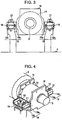
- Fig. 6 shows an arrangement of devices in an engine room 7 of a hydraulic excavator having only an engine 8 as a power source, as viewed from a back side of a machine.
- a power unit U1 is formed by connecting a hydraulic pump 9 in series with the engine 8.
- Reference numeral 10 denotes a cooling fan directly connected to the engine 8.
- a center of gravity X1 of the entire unit when viewed from the back side (or a front side) is slightly displaced towards the pump from an engine center of gravity X2.
- mount devices 11 and 12 are provided on respective sides of the center of gravity X1 of the power unit in an axial direction.
- the mount device at one side (hereunder referred to as the "left mount device” in accordance with directions defined in Fig. 6 ) 11 is provided at the engine 8.
- the mount device at the other side (hereunder referred to as the "right mount device” in accordance with directions defined in Fig. 6 ) 12 is provided at a fly wheel housing 13 accommodating a fly wheel.
- the mount devices 11 and 12 each include a vibration absorbing mechanism that attenuates vibration by a resilient member such as rubber or a spring.
- the distance between the center of gravity X1 of the power unit and one of supporting points and the distance between the center of gravity X1 of the power unit and the other of the supporting points are substantially equal to each other. Accordingly, the overall weight of the power unit U1 is substantially equally shared by the mount devices 11 and 12 at both sides.
- Patent Document 1 Japanese Unexamined Patent Application Publication No. 2003-90387
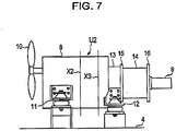
- a power unit U2 is formed by providing a generator motor 14 between an engine 8 and a hydraulic pump 9.
- the generator motor 14 operates as an electric generator and an electric motor.
- An engine-side flange 15 and a pump-side flange 16 are provided on the left and right of the generator motor 14, respectively, so as to project towards the outer periphery while they act as end covers.
- the flanges 15 and 16 are formed of thick plates, respectively.
- the engine-side flange 15 is connected to a fly wheel housing 13 at the engine 8, and the pump-side flange 16 is connected to the hydraulic pump 9.
- Patent Document 2 Japanese Unexamined Patent Application Publication No. 2002-227241
- a center of gravity X3 of the power unit is shifted considerably towards the hydraulic pump 9 from the center of gravity X1 of the power unit U1 for the hydraulic excavator in accordance with the addition of the generator motor 14.
- the left mount device may have insufficient strength due to an increase in load on the left mount device 11, or vibration may tend to occur.
- the generator motor 14 is not directly supported. Therefore, its own weight and the weight of the hydraulic pump act upon the generator motor 14. Consequently, a force is forcefully generated at an internal structure through a rotary shaft, thereby adversely affecting the durability and performance of the generator motor 14.
- a hybrid construction machine comprising an engine, a generator motor, a hydraulic pump, all of which constitute a power unit, and are connected in series, with the generator motor being disposed between the engine and the hydraulic pump and with a center of gravity of the entire power unit being positioned closer to the generator motor than a center of gravity of the engine.
- mount devices are disposed at the engine and the generator motor, respectively, with the center of gravity of the entire power unit being disposed therebetween.
- the power unit is supported on a body frame of the machine by the mount devices. Therefore, it is possible to stably support the power unit with the distance between the center of gravity of the power unit and the mount device at one side and the distance between the center of gravity of the power unit and the mount device at the other side being substantially equal to each other.
- the generator motor is directly supported by the mount device, it is possible to reduce a load applied to the generator motor, and to protect an internal structure, so that actual performance and durability can be ensured.
- an engine-side flange connected to the engine be provided at one side of the generator motor in an axial direction thereof, a pump-side flange connected to the hydraulic pump be provided at the opposite side, a mount installation bracket be provided at a side of each of the flanges, and the generator-motor-side mount device be mounted to the mount installation bracket.
- a plurality of the mount installation brackets and a plurality of the generator-motor-side mount devices be provided at respective sides of the power unit in a direction perpendicular to an axial direction of the power unit.
- the mount devices at the generator motor are provided at respective sides of the power unit in a direction perpendicular to the axial direction of the power unit (front-back direction in the excavator shown in Fig. 5 ), it is possible to further stabilize a supporting state of the entire power unit and the generator motor.
- the hybrid construction machine further comprise an engine-side suspension part and a generator-motor-side suspension part for suspending the entire power unit, that the generator-motor-side suspension part be provided at the mount installation bracket.
- the entire power unit can be suspended with the suspension parts at the engine and the generator motor, it is possible to transport the power unit as one assembly and install it on a machine. Therefore, it is possible to enhance transportability and increase assembly work efficiency.
- the suspension part at the generator motor is provided at a mount installation bracket, that is, since a suspension point at one side of the power unit in the axial direction is set at the generator motor, the power unit can be suspended in a well-balanced state at both sides thereof that are at substantially equal distances from the center of gravity of the power unit.
- suspension parts are formed as parts of the mount installation brackets, costs are reduced and assembly is facilitated.
- the mount installation brackets are installed on both the engine-side flange and the pump-side flange originally provided at the generator motor, and the mount device at the generator motor side is provided at the bracket, it is possible to increase the strength of the mount devices themselves for stabilizing a supporting state of the power unit, and to use the flanges at both sides as mount device installation members to reduce costs, facilitate assembly, and increase space efficiency.
- the present invention is applied to a hybrid excavator.
- Fig. 1 shows a power unit in an engine room and a supporting structure thereof, as viewed from a back side of a machine.
- Fig. 1 shows that (I) a power unit U2 is formed by providing a generator motor 14 between an engine 8 and a hydraulic pump 9, (II) an engine-side flange 15 and a pump-side flange 16, which have the form of thick plates, are provided on the left and right of the generator motor 14, respectively, so as to project towards the outer periphery while they act as end covers; and the engine-side flange 15 is connected to a fly wheel housing 13 at the engine 8, and the pump-side flange 16 is connected to the hydraulic pump 9, and (III) a center of gravity X3 of the power unit is shifted considerably towards the hydraulic pump from the center of gravity X1 of the hydraulic excavator power unit U1 (shown in Fig. 6 ).
- the features of (I) to (III) are the same as those of the related art shown in Fig. 7 (when a supporting structure of the hydraulic shovel power unit U1 shown in Fig. 6 is applied to the hybrid excavator power unit U2).
- mount devices 17 and 18 each including a vibrating absorbing structure, are provided on respective sides of the center of gravity X3 of the power unit in an axial direction.
- the mount devices 17 and 18 will be referred to as the “left mount devices 17" and the “right mount devices 18 as viewed from the back side of the machine.
- the entire power unit 2 is supported on an upper frame 4.
- the left mount devices 17 are provided at an end portion of the engine 8 opposite to the pump (that is, on the left of a center of gravity X2 of the engine).
- the right mount devices 18 are mounted to a generator motor 14 through mount installation brackets 19.
- the mount installation brackets 19 each include a vertical plate portion 19a and a horizontal plate portion 19b.
- the vertical plate portions 19a are mounted on respective sides of each of the flanges 15 and 16 at both sides of the generator motor 14.
- the right mount devices 18 are mounted to substantially the center of the horizontal plate portions 19b (that is, at substantially the center in an axial direction of the generator motor 14).
- the mount installation brackets 19 are mounted to front and back side surfaces of each of the flanges 15 and 16.
- the right mount devices 18 are mounted to the brackets 19.
- the right mount devices 18 are provided at respective sides of the power unit U2 in a direction perpendicular to an axial direction thereof (that is, in a front-back direction) so as to be symmetrical or substantially symmetrical with respect to the center of the generator motor.
- the power unit supporting structure it is possible to stably support the power unit U2 by setting a distance L1 between the power-unit center of gravity X3 and the mount devices 17 and a distance L2 between the power-unit center of gravity X3 and the mount devices 18 substantially equal to each other.
- the generator motor 14 Since the generator motor 14 is directly supported by the mount devices 18, it is possible to reduce a load applied to the generator motor 14, and to protect an internal structure, so that actual performance and durability can be ensured.
- mount installation brackets 19 are mounted to each of the engine-side flange 15 and the pump-side flange 16 originally provided at the generator motor 14, and the mount devices 18 at the generator motor are provided at the respective brackets 19, it is possible to increase the strengths of the mount devices 18 themselves to further stabilize a supporting state of the entire power unit.
- an engine-side suspension part 20 is provided at an upper surface of an end portion opposite to the pump of the engine 8
- generator-motor-side suspension parts 21 and 21 are provided at the horizontal plate portions 19a and 19b of the respective mount installation brackets 19 and 19.
- the suspension parts 20, 21, and 21 make it possible to suspend the entire power unit U2 at three suspension points with, for example, a crane 22 (only its hook is shown). For this reason, it is possible to transport the power unit U2 as one assembly and install it on a machine. Therefore, it is possible to enhance transportability and increase assembly work efficiency.
- the suspension parts 21 and 21 at the generator motor are provided at the mount installation brackets 19 and 19, that is, since a suspension point at one side (right side) of the power unit U2 in the axial direction is set at the generator motor 14, the power unit U2 can be suspended in a well-balanced state with the distance between the center of gravity X3 and one side of the power unit U2 and the distance between the center of gravity X3 and the other side of the power unit U2 being substantially the same.
- suspension parts 21 are formed as parts of the mount installation brackets 19, costs are reduced and assembly is facilitated.
- a hybrid construction machine includes an engine, a generator motor, and a hydraulic pump. They constitute a power unit, and are connected in series, with the generator motor being disposed between the engine and the hydraulic pump and with a center of gravity of the entire power unit being positioned closer to the generator motor than the center of gravity of the engine.
- a mount installation bracket is mounted at a side of each flange disposed at a corresponding side of the generator motor.
- a generator-motor-side mount device is mounted to the bracket.
Landscapes
- Engineering & Computer Science (AREA)
- Chemical & Material Sciences (AREA)
- Combustion & Propulsion (AREA)
- Transportation (AREA)
- Mechanical Engineering (AREA)
- Civil Engineering (AREA)
- Mining & Mineral Resources (AREA)
- General Engineering & Computer Science (AREA)
- Structural Engineering (AREA)
- Arrangement Or Mounting Of Propulsion Units For Vehicles (AREA)
- Hybrid Electric Vehicles (AREA)
- Operation Control Of Excavators (AREA)
- Forklifts And Lifting Vehicles (AREA)
Claims (4)
- Hybridbaumaschine mit:einer Kraftmaschine (8);einem Generator-Motor (14);einer Hydraulikpumpe (9);einer kraftmaschinenseitigen Halterungsvorrichtung (17); undeiner Generator-Motor-seitigen Halterungsvorrichtung (18),wobei die Kraftmaschine (8), der Generator-Motor (14) und die Hydraulikpumpe (9) eine Leistungseinheit (UI) bilden,wobei die Kraftmaschine (8), der Generator-Motor (14) und die Hydraulikpumpe (9) in Reihe verbunden sind, wobei der Generator-Motor (14) zwischen der Kraftmaschine (8) und der Hydraulikpumpe (9) angeordnet ist,wobei die kraftmaschinenseitige Halterungsvorrichtung (17) und die Generator-Motor-seitige Halterungsvorrichtung (18) an der Kraftmaschine (8) und dem Generator-Motor (14) jeweils angeordnet sind, wobei ein Schwerpunkt (X3) der gesamten Leistungseinheit (UI) dazwischen angeordnet ist, undwobei die Leistungseinheit (UI) an einem Körperrahmen der Kraftmaschine durch die Montagevorrichtungen (17, 18) gestützt ist, dadurch gekennzeichnet, dassder Schwerpunkt (X3) der gesamten Leistungseinheit (UI) näher an dem Generator-Motor (14) als ein Schwerpunkt (X2) der Kraftmaschine (8) positioniert ist.
- Hybridbaumaschine gemäß Anspruch 1, wobei ein kraftmaschinenseitiger Flansch (15), der mit der Kraftmaschine (8) verbunden ist, an einer Seite des Generator-Motors (14) in dessen Achsrichtung vorgesehen ist,wobei ein pumpenseitiger Flansch (16), der mit der Hydraulikpumpe (9) verbunden ist, an der entgegengesetzten Seite vorgesehen ist,wobei ein Halterungsinstallationsbügel (19) an einer Seite eines jeden der Flansche (15, 16) vorgesehen ist, undwobei die Generator-Motor-seitige Halterungsvorrichtung (18) an dem Halterungsinstallationsbügel (19) montiert ist.
- Hybridbaumaschine gemäß Anspruch 2, wobei eine Vielzahl der Halterungsinstallationsbügel (19) und eine Vielzahl der Generator-Motor-seitigen Halterungsvorrichtungen (18) an jeweiligen Seiten der Leistungseinheit (UI) in einer Richtung vorgesehen sind, die senkrecht zu einer Achsrichtung der Leistungseinheit (UI) verläuft.
- Hybridbaumaschine gemäß Anspruch 2, ferner mit einem kraftmaschinenseitigen Aufhängungsteil (20) und einem Generator-Motor-seitigen Aufhängungsteil (21) zum Aufhängen der gesamten Leistungseinheit (UI), wobei das Generator-Motor-seitige Aufhängungsteil (20) an dem Halterungsinstallationsbügel (19) vorgesehen ist.
Applications Claiming Priority (1)
| Application Number | Priority Date | Filing Date | Title |
|---|---|---|---|
| JP2009224627A JP5445000B2 (ja) | 2009-09-29 | 2009-09-29 | ハイブリッド建設機械 |
Publications (3)
| Publication Number | Publication Date |
|---|---|
| EP2302139A2 EP2302139A2 (de) | 2011-03-30 |
| EP2302139A3 EP2302139A3 (de) | 2014-09-03 |
| EP2302139B1 true EP2302139B1 (de) | 2017-06-21 |
Family
ID=43127829
Family Applications (1)
| Application Number | Title | Priority Date | Filing Date |
|---|---|---|---|
| EP10173059.6A Not-in-force EP2302139B1 (de) | 2009-09-29 | 2010-08-17 | Hybride Baumaschine |
Country Status (4)
| Country | Link |
|---|---|
| US (1) | US8469136B2 (de) |
| EP (1) | EP2302139B1 (de) |
| JP (1) | JP5445000B2 (de) |
| CN (1) | CN102032314B (de) |
Families Citing this family (24)
| Publication number | Priority date | Publication date | Assignee | Title |
|---|---|---|---|---|
| JP5111409B2 (ja) * | 2009-02-02 | 2013-01-09 | ヤンマー株式会社 | 作業車輌 |
| JP5296640B2 (ja) * | 2009-08-31 | 2013-09-25 | 株式会社小松製作所 | 作業車両および作業車両における発電機モータの取り外し方法 |
| JP5247848B2 (ja) * | 2011-03-31 | 2013-07-24 | 株式会社小松製作所 | 建設機械 |
| JP5261589B1 (ja) * | 2012-04-24 | 2013-08-14 | 株式会社小松製作所 | ブルドーザ |
| JP6051581B2 (ja) * | 2012-04-26 | 2016-12-27 | ダイキン工業株式会社 | 建設機械用ハイブリッド構造体 |
| US10414266B1 (en) * | 2017-04-28 | 2019-09-17 | Oshkosh Defense, Llc | Vehicle cooling systems and methods |
| US12491943B1 (en) | 2013-03-10 | 2025-12-09 | Oshkosh Defense, Llc | Systems and methods for a military vehicle |
| US9303715B2 (en) | 2013-03-10 | 2016-04-05 | Oshkosh Defense, Llc | Limiting system for a vehicle suspension component |
| JP6183402B2 (ja) * | 2015-04-16 | 2017-08-23 | コベルコ建機株式会社 | 建設機械の上部旋回体 |
| JP6572119B2 (ja) * | 2015-12-14 | 2019-09-04 | 株式会社クボタ | 産業機械の駆動ユニット支持構造 |
| JP6551276B2 (ja) * | 2016-03-24 | 2019-07-31 | 株式会社豊田自動織機 | エンジンユニット |
| US10214876B2 (en) | 2016-06-21 | 2019-02-26 | Kubota Corporation | Work machine |
| JP6563369B2 (ja) * | 2016-06-21 | 2019-08-21 | 株式会社クボタ | 作業機 |
| CA3120998C (en) * | 2018-11-27 | 2024-02-27 | Clark Equipment Company | Power machine with bracket mount for engine with pump package |
| WO2020164103A1 (en) * | 2019-02-15 | 2020-08-20 | Guangxi Liugong Machinery Co., Ltd. | Construction machine with flywheel arrangement |
| WO2021042255A1 (en) * | 2019-09-03 | 2021-03-11 | Guangxi Liugong Machinery Co., Ltd. | Driving arrangement for construction machine |
| WO2021042256A1 (en) * | 2019-09-03 | 2021-03-11 | Guangxi Liugong Machinery Co., Ltd. | Driving arrangement for construction machine |
| CN110758079A (zh) * | 2019-09-19 | 2020-02-07 | 中国北方车辆研究所 | 一种履带车辆动力总成悬置装置 |
| GB2587624A (en) | 2019-10-01 | 2021-04-07 | Caterpillar Inc | Mounting system |
| EP4502287A4 (de) * | 2022-03-31 | 2026-04-08 | Kubota Kk | Schwenkbare arbeitsmaschine |
| JP2023150755A (ja) * | 2022-03-31 | 2023-10-16 | 株式会社クボタ | 旋回作業機、及び旋回作業機の組み立て方法 |
| JP2023150754A (ja) * | 2022-03-31 | 2023-10-16 | 株式会社クボタ | 旋回作業機 |
| JP2023150756A (ja) * | 2022-03-31 | 2023-10-16 | 株式会社クボタ | 旋回作業機、及び旋回作業機の組み立て方法 |
| CN117067898A (zh) * | 2023-08-23 | 2023-11-17 | 玉柴芯蓝新能源动力科技有限公司 | 混动系统的四点支撑结构 |
Family Cites Families (21)
| Publication number | Priority date | Publication date | Assignee | Title |
|---|---|---|---|---|
| US1944248A (en) * | 1932-02-26 | 1934-01-23 | Chrysler Corp | Motor mounting |
| US3236326A (en) * | 1962-01-02 | 1966-02-22 | Ford Motor Co | Resilient cantilevered engine support |
| EP0279875B1 (de) * | 1987-02-21 | 1990-06-06 | Dr.Ing.h.c. F. Porsche Aktiengesellschaft | Elastische Lagerung für ein Antriebsaggregat eines Kraftfahrzeugs |
| JP2841121B2 (ja) * | 1990-12-07 | 1998-12-24 | ヤンマーディーゼル株式会社 | 3気筒エンジンの防振支持装置 |
| AT405267B (de) | 1993-08-04 | 1999-06-25 | Steyr Daimler Puch Ag | Stützvorrichtung für ein bergefahrzeug |
| JP3432998B2 (ja) * | 1996-05-14 | 2003-08-04 | 株式会社クボタ | 包囲型エンジン作業機 |
| DE19920052C2 (de) * | 1999-05-03 | 2002-06-06 | Porsche Ag | Lagerung für ein frontseitig angeordnetes Antriebsaggregat eines Kraftfahrzeugs, insbesondere für einen Geländewagen |
| US6223850B1 (en) * | 2000-04-03 | 2001-05-01 | General Motors Corporation | Four point powertrain mounting and transmission inspection cover therefor |
| US6397965B1 (en) * | 2000-08-31 | 2002-06-04 | New Flyer Industries Limited | Engine configuration for mass transit vehicle |
| JP4520649B2 (ja) | 2001-02-06 | 2010-08-11 | 株式会社小松製作所 | ハイブリッド式建設機械 |
| JP2003090387A (ja) | 2001-09-19 | 2003-03-28 | Shin Caterpillar Mitsubishi Ltd | マウント装置 |
| JP2004148843A (ja) * | 2002-09-06 | 2004-05-27 | Honda Motor Co Ltd | 車両の動力源支持構造 |
| JP4072898B2 (ja) * | 2002-11-21 | 2008-04-09 | 株式会社小松製作所 | ハイブリッド式建設機械の機器配置構造 |
| EP2156975B1 (de) * | 2003-06-30 | 2012-02-01 | Toyota Jidosha Kabushiki Kaisha | Hybridfahrzeug und Hybridantriebseinheit |
| JP2005155251A (ja) | 2003-11-27 | 2005-06-16 | Sumitomo (Shi) Construction Machinery Manufacturing Co Ltd | 建設機械用動力系制御装置 |
| US7129595B2 (en) * | 2004-03-22 | 2006-10-31 | General Motors Corporation | Hybrid electro-mechanical vehicular transmission having multiple modular motor/generators assembled from like components |
| US7108098B2 (en) * | 2004-06-30 | 2006-09-19 | Cnh America Llc | Engine subframe mounting arrangement |
| JP4177327B2 (ja) * | 2004-12-28 | 2008-11-05 | 本田技研工業株式会社 | 車両のパワーユニット支持装置 |
| US7575088B2 (en) * | 2005-07-01 | 2009-08-18 | Chrysler Group Llc | Powertrain mounting system |
| JP2008019616A (ja) * | 2006-07-12 | 2008-01-31 | Hitachi Constr Mach Co Ltd | 電動式建設機械 |
| CN101501278B (zh) * | 2006-08-02 | 2013-01-23 | 株式会社小松制作所 | 混合动力作业车辆 |
-
2009
- 2009-09-29 JP JP2009224627A patent/JP5445000B2/ja not_active Expired - Fee Related
-
2010
- 2010-08-13 US US12/856,176 patent/US8469136B2/en not_active Expired - Fee Related
- 2010-08-17 EP EP10173059.6A patent/EP2302139B1/de not_active Not-in-force
- 2010-09-01 CN CN201010287211XA patent/CN102032314B/zh not_active Expired - Fee Related
Non-Patent Citations (1)
| Title |
|---|
| None * |
Also Published As
| Publication number | Publication date |
|---|---|
| US8469136B2 (en) | 2013-06-25 |
| US20110073402A1 (en) | 2011-03-31 |
| CN102032314B (zh) | 2013-06-19 |
| EP2302139A2 (de) | 2011-03-30 |
| JP5445000B2 (ja) | 2014-03-19 |
| EP2302139A3 (de) | 2014-09-03 |
| JP2011073490A (ja) | 2011-04-14 |
| CN102032314A (zh) | 2011-04-27 |
Similar Documents
| Publication | Publication Date | Title |
|---|---|---|
| EP2302139B1 (de) | Hybride Baumaschine | |
| JP7723060B2 (ja) | 建設機械 | |
| US12366049B2 (en) | Swivel working machine | |
| WO2021193300A1 (ja) | 電動式建設機械 | |
| EP2960380A1 (de) | Baumaschine | |
| JP5562901B2 (ja) | 建設機械 | |
| JP5972821B2 (ja) | 発電機モータへのディーゼル酸化触媒装置搭載構造 | |
| JP5446647B2 (ja) | ハイブリッド建設機械のマフラー取付構造 | |
| JP6324921B2 (ja) | 建設機械 | |
| KR102194375B1 (ko) | 방진기능을 향상시킨 링크구조를 갖는 진동리퍼 | |
| JP5436386B2 (ja) | 電動式油圧作業機 | |
| JP2016210343A (ja) | 建設機械の防振構造 | |
| MX2015007792A (es) | Abrazadera de alteracion de frecuencia para un motor electrico. | |
| WO2023189008A1 (ja) | 電動式建設機械及びその製造方法 | |
| JP2023150755A (ja) | 旋回作業機、及び旋回作業機の組み立て方法 | |
| WO2006120812A1 (ja) | 旋回型作業機械 | |
| JP6787384B2 (ja) | 建設機械 | |
| JP5547759B2 (ja) | 建設機械 | |
| JP7815008B2 (ja) | 電動作業機 | |
| JP2024136978A (ja) | 電動作業機、及び電動作業機の組み立て方法 | |
| JP5164177B2 (ja) | キャブを備えた建設機械 | |
| WO2025105298A1 (ja) | 作業機械 | |
| JP2012102502A (ja) | 電動式建設機械 | |
| JP2023150754A (ja) | 旋回作業機 | |
| JP2023150756A (ja) | 旋回作業機、及び旋回作業機の組み立て方法 |
Legal Events
| Date | Code | Title | Description |
|---|---|---|---|
| PUAI | Public reference made under article 153(3) epc to a published international application that has entered the european phase |
Free format text: ORIGINAL CODE: 0009012 |
|
| 17P | Request for examination filed |
Effective date: 20100817 |
|
| AK | Designated contracting states |
Kind code of ref document: A2 Designated state(s): AL AT BE BG CH CY CZ DE DK EE ES FI FR GB GR HR HU IE IS IT LI LT LU LV MC MK MT NL NO PL PT RO SE SI SK SM TR |
|
| AX | Request for extension of the european patent |
Extension state: BA ME RS |
|
| PUAL | Search report despatched |
Free format text: ORIGINAL CODE: 0009013 |
|
| AK | Designated contracting states |
Kind code of ref document: A3 Designated state(s): AL AT BE BG CH CY CZ DE DK EE ES FI FR GB GR HR HU IE IS IT LI LT LU LV MC MK MT NL NO PL PT RO SE SI SK SM TR |
|
| AX | Request for extension of the european patent |
Extension state: BA ME RS |
|
| RIC1 | Information provided on ipc code assigned before grant |
Ipc: B60K 6/48 20071001ALI20140731BHEP Ipc: E02F 9/08 20060101AFI20140731BHEP Ipc: E02F 9/20 20060101ALI20140731BHEP Ipc: B60K 6/42 20071001ALI20140731BHEP Ipc: B60K 6/28 20071001ALI20140731BHEP Ipc: B60K 6/40 20071001ALI20140731BHEP Ipc: B60K 6/12 20060101ALI20140731BHEP |
|
| RIC1 | Information provided on ipc code assigned before grant |
Ipc: B60K 6/12 20060101ALI20161205BHEP Ipc: B60K 6/28 20071001ALI20161205BHEP Ipc: E02F 9/20 20060101ALI20161205BHEP Ipc: B60K 6/48 20071001ALI20161205BHEP Ipc: E02F 9/08 20060101AFI20161205BHEP Ipc: B60K 6/42 20071001ALI20161205BHEP Ipc: B60K 6/40 20071001ALI20161205BHEP |
|
| GRAP | Despatch of communication of intention to grant a patent |
Free format text: ORIGINAL CODE: EPIDOSNIGR1 |
|
| INTG | Intention to grant announced |
Effective date: 20170203 |
|
| GRAS | Grant fee paid |
Free format text: ORIGINAL CODE: EPIDOSNIGR3 |
|
| GRAA | (expected) grant |
Free format text: ORIGINAL CODE: 0009210 |
|
| AK | Designated contracting states |
Kind code of ref document: B1 Designated state(s): AL AT BE BG CH CY CZ DE DK EE ES FI FR GB GR HR HU IE IS IT LI LT LU LV MC MK MT NL NO PL PT RO SE SI SK SM TR |
|
| REG | Reference to a national code |
Ref country code: GB Ref legal event code: FG4D |
|
| REG | Reference to a national code |
Ref country code: CH Ref legal event code: EP |
|
| REG | Reference to a national code |
Ref country code: IE Ref legal event code: FG4D |
|
| REG | Reference to a national code |
Ref country code: AT Ref legal event code: REF Ref document number: 903064 Country of ref document: AT Kind code of ref document: T Effective date: 20170715 |
|
| REG | Reference to a national code |
Ref country code: DE Ref legal event code: R096 Ref document number: 602010043075 Country of ref document: DE |
|
| REG | Reference to a national code |
Ref country code: FR Ref legal event code: PLFP Year of fee payment: 8 |
|
| REG | Reference to a national code |
Ref country code: NL Ref legal event code: MP Effective date: 20170621 |
|
| PG25 | Lapsed in a contracting state [announced via postgrant information from national office to epo] |
Ref country code: HR Free format text: LAPSE BECAUSE OF FAILURE TO SUBMIT A TRANSLATION OF THE DESCRIPTION OR TO PAY THE FEE WITHIN THE PRESCRIBED TIME-LIMIT Effective date: 20170621 Ref country code: LT Free format text: LAPSE BECAUSE OF FAILURE TO SUBMIT A TRANSLATION OF THE DESCRIPTION OR TO PAY THE FEE WITHIN THE PRESCRIBED TIME-LIMIT Effective date: 20170621 Ref country code: FI Free format text: LAPSE BECAUSE OF FAILURE TO SUBMIT A TRANSLATION OF THE DESCRIPTION OR TO PAY THE FEE WITHIN THE PRESCRIBED TIME-LIMIT Effective date: 20170621 Ref country code: NO Free format text: LAPSE BECAUSE OF FAILURE TO SUBMIT A TRANSLATION OF THE DESCRIPTION OR TO PAY THE FEE WITHIN THE PRESCRIBED TIME-LIMIT Effective date: 20170921 Ref country code: GR Free format text: LAPSE BECAUSE OF FAILURE TO SUBMIT A TRANSLATION OF THE DESCRIPTION OR TO PAY THE FEE WITHIN THE PRESCRIBED TIME-LIMIT Effective date: 20170922 |
|
| REG | Reference to a national code |
Ref country code: LT Ref legal event code: MG4D |
|
| REG | Reference to a national code |
Ref country code: AT Ref legal event code: MK05 Ref document number: 903064 Country of ref document: AT Kind code of ref document: T Effective date: 20170621 |
|
| PG25 | Lapsed in a contracting state [announced via postgrant information from national office to epo] |
Ref country code: SE Free format text: LAPSE BECAUSE OF FAILURE TO SUBMIT A TRANSLATION OF THE DESCRIPTION OR TO PAY THE FEE WITHIN THE PRESCRIBED TIME-LIMIT Effective date: 20170621 Ref country code: BG Free format text: LAPSE BECAUSE OF FAILURE TO SUBMIT A TRANSLATION OF THE DESCRIPTION OR TO PAY THE FEE WITHIN THE PRESCRIBED TIME-LIMIT Effective date: 20170921 Ref country code: NL Free format text: LAPSE BECAUSE OF FAILURE TO SUBMIT A TRANSLATION OF THE DESCRIPTION OR TO PAY THE FEE WITHIN THE PRESCRIBED TIME-LIMIT Effective date: 20170621 Ref country code: LV Free format text: LAPSE BECAUSE OF FAILURE TO SUBMIT A TRANSLATION OF THE DESCRIPTION OR TO PAY THE FEE WITHIN THE PRESCRIBED TIME-LIMIT Effective date: 20170621 |
|
| PG25 | Lapsed in a contracting state [announced via postgrant information from national office to epo] |
Ref country code: RO Free format text: LAPSE BECAUSE OF FAILURE TO SUBMIT A TRANSLATION OF THE DESCRIPTION OR TO PAY THE FEE WITHIN THE PRESCRIBED TIME-LIMIT Effective date: 20170621 Ref country code: AT Free format text: LAPSE BECAUSE OF FAILURE TO SUBMIT A TRANSLATION OF THE DESCRIPTION OR TO PAY THE FEE WITHIN THE PRESCRIBED TIME-LIMIT Effective date: 20170621 Ref country code: EE Free format text: LAPSE BECAUSE OF FAILURE TO SUBMIT A TRANSLATION OF THE DESCRIPTION OR TO PAY THE FEE WITHIN THE PRESCRIBED TIME-LIMIT Effective date: 20170621 Ref country code: SK Free format text: LAPSE BECAUSE OF FAILURE TO SUBMIT A TRANSLATION OF THE DESCRIPTION OR TO PAY THE FEE WITHIN THE PRESCRIBED TIME-LIMIT Effective date: 20170621 Ref country code: CZ Free format text: LAPSE BECAUSE OF FAILURE TO SUBMIT A TRANSLATION OF THE DESCRIPTION OR TO PAY THE FEE WITHIN THE PRESCRIBED TIME-LIMIT Effective date: 20170621 |
|
| PG25 | Lapsed in a contracting state [announced via postgrant information from national office to epo] |
Ref country code: ES Free format text: LAPSE BECAUSE OF FAILURE TO SUBMIT A TRANSLATION OF THE DESCRIPTION OR TO PAY THE FEE WITHIN THE PRESCRIBED TIME-LIMIT Effective date: 20170621 Ref country code: PL Free format text: LAPSE BECAUSE OF FAILURE TO SUBMIT A TRANSLATION OF THE DESCRIPTION OR TO PAY THE FEE WITHIN THE PRESCRIBED TIME-LIMIT Effective date: 20170621 Ref country code: IS Free format text: LAPSE BECAUSE OF FAILURE TO SUBMIT A TRANSLATION OF THE DESCRIPTION OR TO PAY THE FEE WITHIN THE PRESCRIBED TIME-LIMIT Effective date: 20171021 Ref country code: SM Free format text: LAPSE BECAUSE OF FAILURE TO SUBMIT A TRANSLATION OF THE DESCRIPTION OR TO PAY THE FEE WITHIN THE PRESCRIBED TIME-LIMIT Effective date: 20170621 |
|
| REG | Reference to a national code |
Ref country code: DE Ref legal event code: R097 Ref document number: 602010043075 Country of ref document: DE |
|
| REG | Reference to a national code |
Ref country code: CH Ref legal event code: PL |
|
| PG25 | Lapsed in a contracting state [announced via postgrant information from national office to epo] |
Ref country code: MC Free format text: LAPSE BECAUSE OF FAILURE TO SUBMIT A TRANSLATION OF THE DESCRIPTION OR TO PAY THE FEE WITHIN THE PRESCRIBED TIME-LIMIT Effective date: 20170621 |
|
| PLBE | No opposition filed within time limit |
Free format text: ORIGINAL CODE: 0009261 |
|
| STAA | Information on the status of an ep patent application or granted ep patent |
Free format text: STATUS: NO OPPOSITION FILED WITHIN TIME LIMIT |
|
| PG25 | Lapsed in a contracting state [announced via postgrant information from national office to epo] |
Ref country code: DK Free format text: LAPSE BECAUSE OF FAILURE TO SUBMIT A TRANSLATION OF THE DESCRIPTION OR TO PAY THE FEE WITHIN THE PRESCRIBED TIME-LIMIT Effective date: 20170621 Ref country code: CH Free format text: LAPSE BECAUSE OF NON-PAYMENT OF DUE FEES Effective date: 20170831 Ref country code: LI Free format text: LAPSE BECAUSE OF NON-PAYMENT OF DUE FEES Effective date: 20170831 |
|
| 26N | No opposition filed |
Effective date: 20180322 |
|
| REG | Reference to a national code |
Ref country code: IE Ref legal event code: MM4A |
|
| REG | Reference to a national code |
Ref country code: BE Ref legal event code: MM Effective date: 20170831 |
|
| PG25 | Lapsed in a contracting state [announced via postgrant information from national office to epo] |
Ref country code: LU Free format text: LAPSE BECAUSE OF NON-PAYMENT OF DUE FEES Effective date: 20170817 |
|
| REG | Reference to a national code |
Ref country code: FR Ref legal event code: PLFP Year of fee payment: 9 |
|
| PG25 | Lapsed in a contracting state [announced via postgrant information from national office to epo] |
Ref country code: IE Free format text: LAPSE BECAUSE OF NON-PAYMENT OF DUE FEES Effective date: 20170817 |
|
| PG25 | Lapsed in a contracting state [announced via postgrant information from national office to epo] |
Ref country code: BE Free format text: LAPSE BECAUSE OF NON-PAYMENT OF DUE FEES Effective date: 20170831 Ref country code: SI Free format text: LAPSE BECAUSE OF FAILURE TO SUBMIT A TRANSLATION OF THE DESCRIPTION OR TO PAY THE FEE WITHIN THE PRESCRIBED TIME-LIMIT Effective date: 20170621 |
|
| PG25 | Lapsed in a contracting state [announced via postgrant information from national office to epo] |
Ref country code: MT Free format text: LAPSE BECAUSE OF NON-PAYMENT OF DUE FEES Effective date: 20170817 |
|
| RIC2 | Information provided on ipc code assigned after grant |
Ipc: B60K 6/48 20071001ALI20161205BHEP Ipc: E02F 9/08 20060101AFI20161205BHEP Ipc: E02F 9/20 20060101ALI20161205BHEP Ipc: B60K 6/42 20071001ALI20161205BHEP Ipc: B60K 6/28 20071001ALI20161205BHEP Ipc: B60K 6/40 20071001ALI20161205BHEP Ipc: B60K 6/12 20060101ALI20161205BHEP |
|
| PG25 | Lapsed in a contracting state [announced via postgrant information from national office to epo] |
Ref country code: HU Free format text: LAPSE BECAUSE OF FAILURE TO SUBMIT A TRANSLATION OF THE DESCRIPTION OR TO PAY THE FEE WITHIN THE PRESCRIBED TIME-LIMIT; INVALID AB INITIO Effective date: 20100817 |
|
| PG25 | Lapsed in a contracting state [announced via postgrant information from national office to epo] |
Ref country code: CY Free format text: LAPSE BECAUSE OF NON-PAYMENT OF DUE FEES Effective date: 20170621 |
|
| PG25 | Lapsed in a contracting state [announced via postgrant information from national office to epo] |
Ref country code: MK Free format text: LAPSE BECAUSE OF FAILURE TO SUBMIT A TRANSLATION OF THE DESCRIPTION OR TO PAY THE FEE WITHIN THE PRESCRIBED TIME-LIMIT Effective date: 20170621 |
|
| PG25 | Lapsed in a contracting state [announced via postgrant information from national office to epo] |
Ref country code: TR Free format text: LAPSE BECAUSE OF FAILURE TO SUBMIT A TRANSLATION OF THE DESCRIPTION OR TO PAY THE FEE WITHIN THE PRESCRIBED TIME-LIMIT Effective date: 20170621 |
|
| PG25 | Lapsed in a contracting state [announced via postgrant information from national office to epo] |
Ref country code: PT Free format text: LAPSE BECAUSE OF FAILURE TO SUBMIT A TRANSLATION OF THE DESCRIPTION OR TO PAY THE FEE WITHIN THE PRESCRIBED TIME-LIMIT Effective date: 20170621 |
|
| PG25 | Lapsed in a contracting state [announced via postgrant information from national office to epo] |
Ref country code: AL Free format text: LAPSE BECAUSE OF FAILURE TO SUBMIT A TRANSLATION OF THE DESCRIPTION OR TO PAY THE FEE WITHIN THE PRESCRIBED TIME-LIMIT Effective date: 20170621 |
|
| PGFP | Annual fee paid to national office [announced via postgrant information from national office to epo] |
Ref country code: GB Payment date: 20200818 Year of fee payment: 11 Ref country code: FR Payment date: 20200715 Year of fee payment: 11 Ref country code: DE Payment date: 20200804 Year of fee payment: 11 |
|
| PGFP | Annual fee paid to national office [announced via postgrant information from national office to epo] |
Ref country code: IT Payment date: 20200713 Year of fee payment: 11 |
|
| REG | Reference to a national code |
Ref country code: DE Ref legal event code: R119 Ref document number: 602010043075 Country of ref document: DE |
|
| GBPC | Gb: european patent ceased through non-payment of renewal fee |
Effective date: 20210817 |
|
| PG25 | Lapsed in a contracting state [announced via postgrant information from national office to epo] |
Ref country code: IT Free format text: LAPSE BECAUSE OF NON-PAYMENT OF DUE FEES Effective date: 20210817 Ref country code: GB Free format text: LAPSE BECAUSE OF NON-PAYMENT OF DUE FEES Effective date: 20210817 Ref country code: FR Free format text: LAPSE BECAUSE OF NON-PAYMENT OF DUE FEES Effective date: 20210831 Ref country code: DE Free format text: LAPSE BECAUSE OF NON-PAYMENT OF DUE FEES Effective date: 20220301 |