EP2296112A2 - Energieverwaltungssystem und Energieverwaltungsverfahren - Google Patents
Energieverwaltungssystem und Energieverwaltungsverfahren Download PDFInfo
- Publication number
- EP2296112A2 EP2296112A2 EP10175052A EP10175052A EP2296112A2 EP 2296112 A2 EP2296112 A2 EP 2296112A2 EP 10175052 A EP10175052 A EP 10175052A EP 10175052 A EP10175052 A EP 10175052A EP 2296112 A2 EP2296112 A2 EP 2296112A2
- Authority
- EP
- European Patent Office
- Prior art keywords
- energy
- amount
- energy management
- adjustment
- management system
- Prior art date
- Legal status (The legal status is an assumption and is not a legal conclusion. Google has not performed a legal analysis and makes no representation as to the accuracy of the status listed.)
- Ceased
Links
Images


Classifications
-
- H—ELECTRICITY
- H02—GENERATION; CONVERSION OR DISTRIBUTION OF ELECTRIC POWER
- H02J—CIRCUIT ARRANGEMENTS OR SYSTEMS FOR SUPPLYING OR DISTRIBUTING ELECTRIC POWER; SYSTEMS FOR STORING ELECTRIC ENERGY
- H02J3/00—Circuit arrangements for ac mains or ac distribution networks
- H02J3/12—Circuit arrangements for ac mains or ac distribution networks for adjusting voltage in ac networks by changing a characteristic of the network load
- H02J3/14—Circuit arrangements for ac mains or ac distribution networks for adjusting voltage in ac networks by changing a characteristic of the network load by switching loads on to, or off from, network, e.g. progressively balanced loading
-
- G—PHYSICS
- G06—COMPUTING; CALCULATING OR COUNTING
- G06F—ELECTRIC DIGITAL DATA PROCESSING
- G06F1/00—Details not covered by groups G06F3/00 - G06F13/00 and G06F21/00
- G06F1/26—Power supply means, e.g. regulation thereof
- G06F1/32—Means for saving power
- G06F1/3203—Power management, i.e. event-based initiation of a power-saving mode
-
- H—ELECTRICITY
- H02—GENERATION; CONVERSION OR DISTRIBUTION OF ELECTRIC POWER
- H02J—CIRCUIT ARRANGEMENTS OR SYSTEMS FOR SUPPLYING OR DISTRIBUTING ELECTRIC POWER; SYSTEMS FOR STORING ELECTRIC ENERGY
- H02J13/00—Circuit arrangements for providing remote indication of network conditions, e.g. an instantaneous record of the open or closed condition of each circuitbreaker in the network; Circuit arrangements for providing remote control of switching means in a power distribution network, e.g. switching in and out of current consumers by using a pulse code signal carried by the network
- H02J13/00006—Circuit arrangements for providing remote indication of network conditions, e.g. an instantaneous record of the open or closed condition of each circuitbreaker in the network; Circuit arrangements for providing remote control of switching means in a power distribution network, e.g. switching in and out of current consumers by using a pulse code signal carried by the network characterised by information or instructions transport means between the monitoring, controlling or managing units and monitored, controlled or operated power network element or electrical equipment
- H02J13/00028—Circuit arrangements for providing remote indication of network conditions, e.g. an instantaneous record of the open or closed condition of each circuitbreaker in the network; Circuit arrangements for providing remote control of switching means in a power distribution network, e.g. switching in and out of current consumers by using a pulse code signal carried by the network characterised by information or instructions transport means between the monitoring, controlling or managing units and monitored, controlled or operated power network element or electrical equipment involving the use of Internet protocols
-
- H—ELECTRICITY
- H02—GENERATION; CONVERSION OR DISTRIBUTION OF ELECTRIC POWER
- H02J—CIRCUIT ARRANGEMENTS OR SYSTEMS FOR SUPPLYING OR DISTRIBUTING ELECTRIC POWER; SYSTEMS FOR STORING ELECTRIC ENERGY
- H02J2310/00—The network for supplying or distributing electric power characterised by its spatial reach or by the load
- H02J2310/50—The network for supplying or distributing electric power characterised by its spatial reach or by the load for selectively controlling the operation of the loads
- H02J2310/56—The network for supplying or distributing electric power characterised by its spatial reach or by the load for selectively controlling the operation of the loads characterised by the condition upon which the selective controlling is based
- H02J2310/58—The condition being electrical
-
- Y—GENERAL TAGGING OF NEW TECHNOLOGICAL DEVELOPMENTS; GENERAL TAGGING OF CROSS-SECTIONAL TECHNOLOGIES SPANNING OVER SEVERAL SECTIONS OF THE IPC; TECHNICAL SUBJECTS COVERED BY FORMER USPC CROSS-REFERENCE ART COLLECTIONS [XRACs] AND DIGESTS
- Y02—TECHNOLOGIES OR APPLICATIONS FOR MITIGATION OR ADAPTATION AGAINST CLIMATE CHANGE
- Y02B—CLIMATE CHANGE MITIGATION TECHNOLOGIES RELATED TO BUILDINGS, e.g. HOUSING, HOUSE APPLIANCES OR RELATED END-USER APPLICATIONS
- Y02B70/00—Technologies for an efficient end-user side electric power management and consumption
- Y02B70/30—Systems integrating technologies related to power network operation and communication or information technologies for improving the carbon footprint of the management of residential or tertiary loads, i.e. smart grids as climate change mitigation technology in the buildings sector, including also the last stages of power distribution and the control, monitoring or operating management systems at local level
- Y02B70/3225—Demand response systems, e.g. load shedding, peak shaving
-
- Y—GENERAL TAGGING OF NEW TECHNOLOGICAL DEVELOPMENTS; GENERAL TAGGING OF CROSS-SECTIONAL TECHNOLOGIES SPANNING OVER SEVERAL SECTIONS OF THE IPC; TECHNICAL SUBJECTS COVERED BY FORMER USPC CROSS-REFERENCE ART COLLECTIONS [XRACs] AND DIGESTS
- Y04—INFORMATION OR COMMUNICATION TECHNOLOGIES HAVING AN IMPACT ON OTHER TECHNOLOGY AREAS
- Y04S—SYSTEMS INTEGRATING TECHNOLOGIES RELATED TO POWER NETWORK OPERATION, COMMUNICATION OR INFORMATION TECHNOLOGIES FOR IMPROVING THE ELECTRICAL POWER GENERATION, TRANSMISSION, DISTRIBUTION, MANAGEMENT OR USAGE, i.e. SMART GRIDS
- Y04S20/00—Management or operation of end-user stationary applications or the last stages of power distribution; Controlling, monitoring or operating thereof
- Y04S20/20—End-user application control systems
- Y04S20/222—Demand response systems, e.g. load shedding, peak shaving
Definitions
- Embodiments described herein relate generally to an energy management system which calculates an optimum adjustment amount in a case where an energy supply device requests an energy demand device to adjust the amount of energy to be supplied, and an energy management method.
- an air conditioner consumes much power at the peak of power consumption on a hot day in summer or the like.
- a set temperature of each air conditioner is merely raised as much as 2°C to 3°C, power saving is noticeably realized.
- DSM demand side management
- a power company and the like regulate the power consumption of an electric device (including the air conditioner) for a household, an office building and the like by remote control.
- industry organization 'Echonet Consortium' for household apparatus control has started a demonstration experiment of a DSM service in Tokyo from November of 1999.
- Examples of a control method concerning DSM include a restricting or peak cutting of the whole power load by forced load blocking (selective load blocking), and leveling of the load by a shift of the load use period of time.
- a priority of the load to be blocked and an adjustment rule of the load need to be beforehand determined.
- This load adjustment logic is a unilateral energy management technology in which the state of the energy demand device is not taken into consideration.
- Document 1 Jpn. Pat. Appln. KOKAI Publication No. 2002-10532 discloses an energy management system which manages the supply of the energy to the energy demand device. In Document 1, however, unilateral demand control from the energy supply device to the energy demand device is performed, and hence any request from the energy demand device to the energy supply device is not reflected.
- an energy management system includes an energy supply device and an energy demand device. Energy is supplied from the energy supply device to the energy demand device.
- the energy management system comprises a first energy management device, a second energy management device, storage sections, calculating sections.
- the first energy management device is applied for the energy supply device.
- the second energy management device is applied for the energy demand device.
- the storage sections are included in the first energy management device and the second energy management device, respectively, and in which a condition as to comply with an adjustment request of the energy supplied from the energy supply device to the energy demand device is stored.
- the calculating sections are included in the first energy management device and the second energy management device, respectively, and which cooperate to execute negotiation function calculating an energy adjustment amount satisfying the condition.
- an energy supply device is, for example, a facility of a power company.
- the energy supply device supplies energy or a service to an energy demand device.
- the energy supply device is not limited to the facility of the power company.
- the energy supply device may be, for example, a facility of an energy provider such as a gas company or a district heat supply company.
- the energy provider device may be a facility of a service provider such as an emission right company, an energy management agency service company or an energy saving support service company for providing various services concerning energy management.
- the energy demand device corresponds to at least one of various load facilities of energy consumer side.
- the energy demand device may be a facility of a collective housing, an apartment building, office, tenamt, factory, or plant or the like.
- the energy demand device is a facility comprising at least one of various types of energy load devices (hereinafter referred to as the loads).
- the energy management system 1 is a hierarchical type energy management system.
- the energy management system 1 comprises energy management devices 1-1, 1-2, 2-1 to 2-m and n-1 to n-m which belong to layers.
- the energy management device of the energy supply device belongs to the uppermost layer (the first layer) of the energy management system 1 among the layers.
- the energy management devices of the uppermost layer are managed by the energy provider or the service provider.
- the energy demand devices comprise energy management devices n-1 to n-m of the lowermost layer (the n-th layer) and the loads L1 to Lm, respectively.
- the loads Lm-1 and load Lm are a distributed power source facility and a power storage device.
- the energy management system 1 has two layers at minimum, and has an n-layer constitution of two or more layers.
- the number of the energy management devices and the number of the loads attached to the energy management devices increase in lower layers.
- the energy management devices of an intermediate layer can execute negotiation function for energy adjustment (regulation) with energy management devices of the upper and lower layers. That is, the energy management system 1 has a negotiating function of performing bidirectional communication among the energy management devices of the respective layers to regulate the adjustment amount of energy.
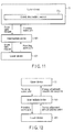
- FIG. 2 is a block diagram showing a first example of a constitution of the three-layer energy management system 1.
- An energy supply device 10 belongs to the first layer.
- a facility 100 of an energy management organization of the collective housing, a building management organization of a tenant building or the like belongs to the second layer.
- An energy demand device 200 used in each household, each building tenant or the like belongs to the third layer.
- the layers are connected to one another via a network such as a telephone network or internet. It is to be noted that in FIG. 2 , a plurality of devices may be present in each layer as shown in FIG. 1 .
- the layers comprise the energy management devices 10, 101 and 201, respectively.
- the energy supply device 10 comprises an upper energy management device (hereinafter referred to as the upper device) 11.
- the facility 100 comprises an intermediate energy management device (hereinafter referred to as the intermediate device) 101.
- the energy demand device 200 comprises a lower energy management device (hereinafter referred to as the lower device) 201.
- the upper device 11 comprises a control calculating section 20.
- the intermediate device 101 comprises a control calculating section 110.
- the lower device 201 comprises a control calculating section 210.
- the control calculating sections 20, 110, and 210 includes negotiation functions 20a, 110a, and 210a, respectively.
- An energy adjustment request (e.g., an energy cut (reduce) request) transmitted from the energy supply device 10 is transmitted to the energy demand device 200 via the facility 100.
- the intermediate device 101 of the facility 100 and the lower device 201 of the energy demand device 200 perform bidirectional communication referred to as negotiation with respect to the upper device 11 of the energy supply device 10.
- the negotiation is generically transmission/reception where one device provides a request condition concerning energy adjusting and the other device provides a possible condition or reward (compensation) condition with respect to the request condition.
- the request condition an eco point, a score card, etc.
- control calculating sections 20, 110 and 210 include functions of distributing an energy adjustment request amount and adding up (calculating) eco point request amounts.
- a common measure such as an eco point is introduced to quantitatively represent, by numeric values, a reward condition with respect to an adjustment of the amount of the energy from the upper device 11 to the lower device 201.
- the eco point is a reward for the adjustment of the energy.
- the eco point can be treated as a local money which can equivalently be exchanged for an economic value or an emission right if necessary.
- the reward eco point is an index value corresponding to the size of the adjustment amount of the energy.
- the index value (the eco point) which is the reward for the energy adjustment is beforehand set.
- the eco point is associated with a digitalized energy cut amount for each period of time when the adjustment is performed, and registered in table data (the score card).
- the energy adjustment amount is the amount of the energy to be adjusted with respect to the adjustment request of the amount of the energy to be supplied from the energy supply device 10 to the energy demand device 200.
- the adjustment request is transmitted from the energy supply device 10 to the energy demand device 200.
- the adjustment amount of the energy may be energy consumption cutting (decrease) such as energy saving or power saving, or energy consumption increase for stabilizing a power system or increasing an operation efficiency.
- data referred to as the score card is used in information transmission executed for the negotiation to regulate the energy adjustment amount.
- the score card includes an attribute value concerning the adjustable energy amount.
- the score card includes, as the attribute value concerning the adjustable energy amount, for example, at least one of:
- the score card is data indicating a relation between the attribute values.
- the score card is table data in which the adjustable amount of the energy is associated with the eco point indicating the value measure of the amount (described later with reference to FIG. 6 or the like).
- the score card in addition to the energy adjustment amount like the present instantaneous value, it is possible to register, as another attribute value, the energy adjustment amount in which a predicted value with respect to a time axis is reflected.
- the energy adjustment request amount (e.g., the cutting request of the energy supply amount) is transmitted from the energy supply device 10 to the energy demand device 200 via the facility 100
- the plurality of upper devices 11, the plurality of intermediate devices 101 and the plurality of lower devices 201 mutually regulate the adjustment amount of the energy (the negotiation) by bidirectional communication.
- the negotiation is executed concerning (1) the energy adjustment request value and eco point request amount, (2) the provideable eco point amount and adjustable energy amount, (3) the score card and the energy adjustment amount or providing eco point amount matching the score card, and the like (described later).
- the energy adjustment request amount is transmitted (provided) from the upper device 11 to the lower device 201 via the intermediate device 101, and the eco point request amount corresponding to this energy adjustment request amount is returned from the lower device 201 to the upper device 11 via the intermediate device 101.
- the provideable eco point amount is transmitted from the upper device 11 to the lower device 201 via the intermediate device 101, and the adjustable energy amount with respect to the provideable eco point amount is returned from the lower device 201 to the upper device 11 via the intermediate device 101.
- the request for the score card is transmitted from the upper device 11 to the lower device 201 via the intermediate device 101, and in response to this request, the score card is transmitted from the lower device 201 to the upper device 11 via the intermediate device 101.
- the energy adjustment amount matching the condition of the score card is transmitted from the upper device 11 to the lower device 201 via the intermediate device 101, to give the eco point to the lower device 201.
- the lower device 201 has a negotiating function 210a with respect to the plurality of intermediate devices 101.
- the lower device 201 has a negotiating function 210a of selecting one intermediate device 101 or a combination of the plurality of intermediate devices so as to minimize the sum of the necessary energy cut amounts or maximize the sum of the requestable eco points (described later). It is to be noted that negotiation will be described later in detail.
- the intermediate device 101 has a function of adding the plurality of score cards of the lower device 201 to the condition of the calculation in the negotiation to divide the energy adjustment request amount or provideable eco point amount transmitted from the upper device 11 into the energy adjustment request amounts or provideable eco point amounts with respect to the plurality of lower devices 201; a function of adding up the adjustable energy amounts or eco point request amounts returned from the lower devices 201 to return the adjustable energy amount or eco point request amount to the upper device 11, and the like.
- the intermediate device 101 has a cycle regulating function of allowing the varying cycles of the negotiation among the upper device 11, the intermediate device 101 and the lower device 201 to locally regulate the inconformity of this cycle of the negotiation.
- the intermediate device 101 has a regulating function of regulating a case where the cycle of the negotiation between the upper device 11 and the intermediate device 101 is different from that of the negotiation between the intermediate device 101 and the lower device 201 or the load of the energy demand device 200 (e.g., a case where one cycle is one hour and the other cycle is one minute or the like).
- This regulating function solves the mismatch of the cycle of the negotiation by adjusting local energy load distribution or utilizing the power storage device.
- the intermediate device 101 has a function of executing change corresponding to a request received from the upper device 11 or the lower device 201 with respect to a self database to return a completion notice of the execution to the upper device 11 or the lower device, when newly receiving an addition request, a cancellation request or a deletion request from the upper device 11 or the lower device 201 (described later).
- the intermediate device 101 and the lower device 201 have a function of summing up the eco points obtained by the negotiation with the upper device 11 to perform, for example, settlement or the like with respect to an device of an eco point/service provider.
- the upper device 11 has a function of summing up the eco points provided by the negotiation with the intermediate device 101 or the lower device 201, to perform settlement or the like with respect to the device of the eco point/service provider (described later).
- FIG. 5 is a block diagram showing an example of a constitution of a score card management function disposed in each energy management device. It is to be noted that the upper device 11 of the energy supply device 10 will be described as an example with reference to FIG. 5 , but this also applies to the intermediate device 101 and the lower device 201.
- the control calculating section 20 of the upper device 11 comprises a score card management section 22.
- the score card management section 22 has a score card distribution/synthesis calculating function of performing the synthesis and distributing calculation of the information of the score card; a function of managing a score card database 25 (a recording function, a search function); a function of reading a template 26 for each energy demand device 200 from the storage section 21; various management functions of the score card; a function of selecting the upper device 11 in a case where the plurality of upper devices 11 are present; a function of distributing the request to the plurality of upper devices 11; a managing function of the new addition of energy adjustment to be executed by the upper device 11, the intermediate device 101 and the lower device 201, and cut cancellation; a settlement function concerning the conversion of the eco point into the emission right or economic value based on a preset conversion rate, and the like.
- the score card management section 22 comprises a score card display/editing section 23 and a score card inferring section 24.
- the score card display/editing section 23 displays/edits the score card.
- the score card inferring section 24 searches for inferring data based on the database of past results (data having a high possibility of matching data acquired from the past data) to display a search result in a connected input/output terminal 300 or the like.
- the energy management system 1 of the first embodiment has the following functions as the various management functions of the score card used in the negotiation.
- an adjustment of the energy adjustment amount between the energy management devices of the layers is realized by the negotiating function 20a, 110a, and 210a using the bidirectional communication.
- the negotiating function 20a, 110a, and 210a uses the score card in which the adjustable energy amounts are associated with the eco points indicating the value measures of the amounts.
- Examples of the score card used in the negotiation are shown in FIG. 6 to FIG. 10 .
- the attribute value concerning the adjustable energy amount of at least one of (1) a adjustable (regulateable) load amount, (2) a shiftable load amount, (3) a adjustable load operation time or adjustable accumulated energy amount, (4) the propriety of the load adjustment blocking and (5) the consumption of the load or the amount of the energy to be generated, and the error amount or the error ratio thereof.
- FIG. 6 to FIG. 10 show, as one example, the score card in a case where the energy demand device 200 is the facility of the general household.
- FIG. 6 shows an example of a case where the load included in the energy demand device 200 is an air conditioner.
- FIG. 7 shows an example of a case where the load is a washing machine.
- FIG. 8 shows an example of a case where the load is a solar power generation facility.
- FIG. 9 shows an example of a case where the load is TV.
- FIG. 10 shows an example of a case where the load is outdoor light.
- a score card shown in FIG. 6 includes an adjustable range of the air conditioner (the energy adjustable range), and also includes an eco point number requested as a reward (a reward eco point).
- the eco point is an index value which is used to request a reward from one device (the intermediate device 101 or the lower device 201) to another device (the energy supply device 10) in a case where the one device accepts the energy adjustment request from the other device.
- the intermediate device 101 or the lower device 201 can decrease in a request range of the energy adjustment request.
- the score card includes a set eco point generated in a case where the energy demand device 200 or the load is forcibly blocked from the upper device 11.
- a score card shown in FIG. 7 includes a shiftable period of time of the washing machine (an energy shiftable period of time), and includes an eco point requested as the reward in each period of time in a case where execution time is shifted to a shiftable period of time. Moreover, the score card includes a set eco point generated in a case where energy supply from the upper device 11 is forcibly blocked.
- a score card shown in FIG. 8 is used to adjust the load of the solar power generation facility.
- the score card includes a predicted value of the amount of the power to be generated (energy demand prediction) and an error ratio of the predicted value (demand error).
- the score card includes a set eco point generated in a case where energy supply from the upper device 11 is forcibly blocked.
- a score card shown in FIG. 9 is used in the load adjustment of the TV, and includes an operation time when the load adjustment can be performed (a daily operation time adjustable range).
- An operation time when the load adjustment of the TV can be performed is, for example, a total use time when a TV switch is turned on in a day.
- a score card shown in FIG. 10 includes a period of time when a load can forcibly be blocked with respect to the outdoor light.
- the score card includes an eco point generated in a case where the energy supply from the upper device 11 is forcibly blocked.
- the above score card includes an eco point corresponding to each adjustable energy amount (a converted eco point value). Moreover, in the above score card, a predicted future value is associated with a time axis. A period of time included in the score card includes a time after the present period of time.
- the above negotiating functions 20a, 110a, and 210a are generically processing of performing the transmission/reception of the energy adjustment request amount, the adjustable energy amount, the corresponding provideable eco point amount, the total eco point amount (the eco point request amount), the score card and the like, to adjust each condition. Consequently, the negotiating functions 20a, 110a, and 210a can optimally distribute the energy adjustment request amount or provideable eco point amount from the upper device 11 to the plurality of lower devices 201. The negotiating functions 20a, 110a, and 210a can optimally distribute optimally distribute the adjustable energy amount or total eco point amount to the plurality of upper devices 11. Furthermore, the negotiating function 20a, 110a, and 210a comprises the managing function of the addition/deletion of the energy management devices in the upper layer or lower layer, the conversion settlement function of the eco point into the emission right or economic value and the like.
- the lower device 201 has the negotiating function 210a for the plurality of upper devices 11 or the plurality of intermediate devices 101.
- This negotiating function 210a selects one upper device 11 or one intermediate device 101 or a combination of a plurality of devices so as to minimize the sum of the necessary energy adjustment amounts or maximize the sum of requested eco points.
- the energy management device belonging to any one of a plurality of layers optimizes the distributing of the energy adjustment amount or the eco point through the negotiation with energy management devices of the lower and upper layers.
- the adjustable energy amount of the lower layer ⁇ (the adjustable energy amount distributed to the j-th upper layer)
- the provideable eco point amount of the lower layer ⁇ (the provideable eco point amount distributed to the j-th upper layer)
- the function of optimally distributing the energy adjustment request amount or provideable eco point amount from the upper device 11 to a plurality of lower layers is as follows, for example, in a certain time section during the use of the air conditioner, the washing machine and the TV.
- the eco point corresponding to the adjustment amount for example, ten eco points are requested with respect to a cut of 10%.
- the adjustment range of the air conditioner is restricted to 50%.
- the energy adjustment request amount from the upper layer which is a restricting condition, is 800 W.
- the energy of the air conditioner is decreased as much as 300 W
- the washing machine is turned off owing to the postponing of the washing to decrease the energy thereof as much as 500 W, and the TV maintains the present state.
- the provideable eco point amount from the upper layer is 50 points.
- the energy of the air conditioner is decreased as much as 250 W
- the washing machine is turned off owing to the postponing of the washing to decrease the energy thereof as much as 500 W, and the TV maintains the present state. This reason is similar to the above reason. It is most efficient to postpone the washing by the washing machine, it is secondly efficient to cut the energy of the air conditioner, and it is thirdly efficient to turn off the TV.
- the provideable eco point amount from the upper layer is 80 points
- the energy of the air conditioner is decreased as much as 500 W
- the washing machine is turned off to decrease the energy thereof as much as 500 W
- the TV is used while maintaining the present state.
- the eco points in this state are 75 points.
- a reason for such control is that the adjustment range of the air conditioner is restricted to be 50%, and it is better to cut the energy consumption of the air conditioner with five points being unused than to use 60 points for turning off the TV.
- a facility of company A and a facility of company B are present as eco point supply service providers.
- the company A imparts one eco point with respect to the cut of 10 W, and imparts 30 eco points at maximum.
- the company B imparts one eco point with respect to the cut of 20 W, and the number of the eco points to be imparted is not limited.
- the score card management section 22 for the control calculating sections 20, 110 and 210 comprises the distributing/adding section 11a which performs the synthesis and distributing calculation of the score card.
- the score cards corresponds to five types of facilities (the air conditioner, the washing machine, the solar power generation facility, the TV and the outdoor light) shown in FIG. 6 to FIG. 10 .
- the distributing/adding section 11a of the upper device 11 synthesizes, for example, the score cards for the five types of facilities into one score card.
- the score card for the air conditioner (1000 W) includes relations of 10 points to a cut of 100 W, 20 points to a cut of 200 W, ..., and 50 points to a cut of 500 W.
- the score card for the washing machine (500 W) includes a relation of 25 points to a cut of 500 W.
- the score card for the TV (300 W) includes a relation of 60 points to the discontinuation of the use.
- the calculation described above in each example is executed in accordance with the score card.
- the score cards can be synthesized. For example, in the example of the optimum distribution of the energy adjustment request amount to the lower device 201, when a cut amount is from 0 W and less than 490 W, the eco point is acquired from 0 point to 49 points by cutting the energy of the air conditioner.
- the washing machine When the cut amount is 500 W, the washing machine is turned off to acquire 25 points. When the cut amount is above 500 W to 1000 W, the washing machine is turned off and the energy of the air conditioner is cut to acquire the eco point from 25 to 75 points. When the cut amount is above 1000 W to 1300 W, the TV is turned off to acquire the eco point from 105 to 135 points. These relations are included in the synthesized score card.
- the energy management system 1 has a constitution of three or more layers including the upper layer (the first layer), the intermediate layer (from the second layer to the n-1-th layer) and the lower layer (the n-th layer).
- the energy management devices 2-1 to 2-m of the intermediate layer allow that the cycle of the negotiation with the energy management devices 1-1 and 1-2 of the upper layer is different from the cycle of the negotiation with the energy management devices n-1 to n-m including the loads L1 to Lm of the lower layer.
- the energy management devices 2-1 to 2-m of the intermediate layer has a regulating function of adjusting the local energy load distribution or utilizing the power storage device to solve mismatch in the case of the occurrence of the mismatch of the negotiation cycle.
- the energy management devices 2-1 to 2-m positioned in the intermediate layer divide, into the energy adjustment amounts of a lower device, the energy adjustment amount to be satisfied with respect to the upper layer in one hour.
- the charge/discharge amount for the power storage device is adjusted.
- a part of the lower layer is the solar power generation facility, it is difficult to predict the amount of the power to be generated by this solar power generation facility. Therefore, an accumulated value for one hour is calculated, the distribution of the load or the power storage device is adjusted, thereby executing demand control or simultaneous commensuration control so as to match the energy adjustment amount requested by the upper layer for one hour.
- the energy management system 1 of FIG. 1 assumes a case where a new energy management device is added to the upper layer or the lower layer in a certain time or a case where the energy management device of the upper layer or the lower layer partially drops down.
- the energy management device of the intermediate layer has a function of executing a change with respect to the database of the energy management device of the intermediate layer based on the request received from the energy management device of the upper layer or the lower layer and returning the completion notice of the execution to the energy management device of the upper layer or the lower layer, when newly receiving an addition request or receiving a cancellation/deletion request from the energy management device of the upper layer or the lower layer.
- the energy management device of the intermediate layer or lower layer processes (sums up) the eco points acquired by the negotiation executed between the device and the energy management device of the upper layer.
- the energy management device of the upper layer processes (sums up) the eco points provided by the negotiation executed between the device and the energy management device of the intermediate layer or lower layer.
- the energy management device of the eco point/service provider has a function of performing the settlement based on the summed eco points. In the settlement, the eco point is exchanged for a price per eco point or an equivalent emission right based on a contract condition determined between the eco point/service provider and an eco point acquirer.
- the reward for the energy adjustment (load adjustment) of each energy demand device can be settled, and a reward can be provided with respect to an owner of the energy demand device.
- the positive load adjustment, the energy saving of the whole society, the power saving and a rational energy operation can be realized.
- the cutting of the energy in the adjustment of the energy has mainly be described, but the embodiment also applies to a case where the energy is increased.
- the functions of the upper device 11, the intermediate device 101 and the lower device 201 can be reversed.
- the lower device 201 may transmit a necessary energy increase amount to the upper device 11 via the intermediate device 101, and the upper device 11 may request the lower device 201 to pay the eco point corresponding to the energy increase amount, via the intermediate device 101.
- the energy management system 1 has a hierarchical constitution of two or more layers. In consequence, it is possible to smoothly manage or execute the energy adjustment, load adjustment, load distribution, reward settlement and the like among stake holders having complicated stakes, for example, the energy provider or the service provider, the management organization of a collective housing or a building, each household or each building tenant and the like.
- the energy adjustment request of the whole energy management system 1 can optimally be distributed to the lower layers.
- Unilateral load adjustment is not imposed on the energy demand device 200 including the load, but smooth energy adjustment can be performed by bidirectional negotiation.
- the score card is used in which the adjustable amount of the energy is associated with the eco point indicating the value measure of the energy, whereby it is possible to quickly and rationally make the determination of the adjustment/burden distribution between the stake holders having the stakes.
- the load adjustment/load control for the energy adjustment is executed by using the attribute value for each load of each energy demand device, for example, the adjustable load amount of the energy, the shiftable load amount, the load operation time/ adjustable accumulated energy amount, the propriety of the load adjustment blocking, the consumption of the load or the amount of the energy to be generated and the error amount or the error ratio, or the like.
- the respective reward measures for the load adjustment can be quantified by the eco point, and the settlement of the rewards can smoothly be performed.
- the adjustment can be executed by using the predicted future value along a time axis. Therefore, the energy management and energy management optimization can be performed based on not only each instantaneous time section but also the predicted value along the time axis.
- the negotiation includes various means for the negotiation by the energy adjustment request amount or the adjustable energy amount, the negotiation by the provideable eco point amount and the eco point request amount, the negotiation by the score card and the like. This enables flexible load adjustment/load control in accordance with situations, whereby the optimum distribution of the load adjustment/load control from the upper layer to the lower layer can rationally be determined.
- the score card is used to transmit information on the negotiation. Furthermore, the energy management system 1 has various management functions of the score card, for example, the display/editing function of the score card, the database management function, the template function for each load, the inferring function based on the database of the past results and the like. In consequence, the negotiation can smoothly be executed.
- the energy management system 1 can execute the processing also in a case where the cycle of the negotiation with the upper layer is different from that of the negotiation with the lower layer. Therefore, for example, even when the energy supply device 10 provides services with respect to a large number of energy demand devices 200 from several hundreds of devices to several tens of millions of devices, the management of the energy by a unit of one day to one hour can be performed by the energy management device of the upper layer, and in the local energy management device of the lower layer, each load can be controlled by a unit of one minute to one second. In consequence, the energy management/control can be executed by an optimum management/control cycle for each layer.
- the optimum upper device 11 can be selected from the plurality of upper devices 11, and electricity is purchased from the plurality of upper devices 11, whereby the load adjustment request from the plurality of upper devices 11 can optimally be distributed and met.
- each energy management device can acquire the notice of the addition or deletion to automatically cope with the addition or deletion.
- the structure of the energy management system 1 can flexibly be changed.
- the energy management system 1 has a settlement function of converting the eco point into the emission right or the economic value, the system can smoothly settle the stakes with the plurality of energy management devices and the plurality of loads.
- a constitution of an energy management system according to a second embodiment will be described with reference to FIG. 15 .
- a negotiation is executed between energy management devices.
- FIG. 15 is a block diagram showing an example of a constitution of the hierarchical type energy management system according to the second embodiment. As shown in FIG. 15 , the second embodiment is different from the first embodiment in that the upper device 11 of the energy supply device 10 and the lower device 201 of the energy demand device 200 perform bidirectional communication in a relation of one to one.
- the energy management system of the second embodiment comprises the energy supply device 10 and the energy demand device 200.
- the energy supply device 10 comprises the upper device 11.
- the upper device 11 comprises the control calculating section 20 and the storage section 21.
- the energy demand device 200 comprises the lower device 201.
- the lower device 201 comprises the control calculating section 210 and the storage section 211.
- a power is supplied as energy from the energy supply device 10 to the energy demand device 200.
- the negotiation function 20a of the upper device 11 and the negotiation function 210a of the lower device 201 perform the bidirectional communication to adjust the adjustment amount of the energy based on the condition beforehand stored in the upper device 11 and the lower device 201.
- FIG. 16 is a block diagram showing an example having a state where an eco point request amount with respect to an energy adjustment request is returned by the lower device 201 which has received the energy adjustment request from the upper device 11 according to the second embodiment.
- FIG. 17 is a flowchart showing a procedure of the energy management system according to the second embodiment.
- the upper device 11 transmits, to the lower device 201, for example, 10 kW as the energy adjustment request indicating the amount of the energy which needs to be cut at a certain time (step S101).
- the lower device 201 which has received the energy adjustment request calculates a cuttable energy amount based on an energy demand of the energy demand device 200, and returns a requested eco point (e.g., 10 points/kW) corresponding to the cuttable energy amount to the upper device 11 (step S102).
- FIG. 18 is a block diagram showing an example in a state where the lower device 201 which has received a provideable eco point amount from the upper device 11 returns an adjustable energy amount corresponding to the provideable eco point amount in the second embodiment.
- the upper device 11 transmits, to the lower device 201, the provideable eco point amount (e.g., 100 points) indicating the eco point which can be supplied from the upper device 11 to the lower device 201.
- the provideable eco point amount e.g., 100 points
- a ratio e.g., 10 points/kW
- the lower device 201 calculates 100 points/10 (points/kW) based on the provideable eco point amount received from the upper device 11, and returns 10 kW as the cuttable energy amount to the upper device 11.
- the upper device 11 which has received the cuttable energy amount determines that when at least 100 points are supplied to the lower device 201, an energy amount of 10 kW can be cut.
- the above data transmission/reception is processing necessary for executing the negotiation. Furthermore, when not only the negotiation in a predetermined time section but also a negotiation for a predetermined period of time are performed, the processing becomes complicated. It is considered that there are usually limits to the eco point which can be provided with respect to the energy cut amount from the upper device 11, and the amount of the energy which can be cut with respect to the eco point (the reward eco point) supplied to the lower device 201. A score card is applied so as to reflect a complicated requirement and condition in the negotiation.
- FIG. 19 is a block diagram showing an example of the negotiation using the score card.
- the upper device 11 transmits a cut request score card to the lower device 201.
- the lower device 201 returns a cut suggestion score card to the upper device 11.
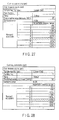
- FIG. 20 is a table showing an example of the cut request score card.
- FIG. 21 is a table showing one example of the cut suggestion score card.
- the cut request score card and the cut suggestion score card respectively, relations among predicted power consumptions in a plurality of time sections of one o'clock, two o'clock and three o'clock on a certain day, the predicted error ratio of a predicted power consumption, the eco point and energy cut request amount at each time, and the cuttable energy amount are shown in function tables.
- the cut request score card of FIG. 20 indicates that 1 point is supplied as the reward eco point from the upper device 11 to the lower device 201 with respect to an energy cut of 10% at one o'clock.
- the negotiation function 210a of the lower device 201 and the negotiation function 20a of the upper device 11 cooperate with each other to execute the negotiation, and calculate an optimum energy cut amount (a compromise point).
- the negotiation function 20a of the upper device 11 further notifies the negotiation function 210a of the increase of the cut amount in a case where the energy supply to the lower device 201 is to be cut as much as possible.
- FIG. 22 is a graph showing an example of a relation between the reward eco point and the energy cut amount at one o'clock in the cut request score card and the cut suggestion score card.
- the eco point value of the cut request score card matches that of the cut suggestion score card in a case where the eco point corresponding to a cut amount of 50% is 5 points.
- the optimum energy cut amount is calculated between the negotiation function 20a of the upper device 11 and the negotiation function 210a of the lower device 201.
- an agreement is made between the negotiation function 20a of the upper device 11 and the negotiation function 210a of the lower device 201 on a condition that the eco point corresponding to a cut amount of 10% is 1 point.
- an agreement is made between the upper device 11 and the lower device 201 on a condition that the eco point corresponding to a cut amount of 60% is 3 points.
- the negotiation of the hierarchical type energy management system according to the second embodiment will be described with respect to an example in which the energy is cut.
- the present embodiment also applies to a case where the energy is increased.
- the functions of the upper device 11 and the lower device 201 can be reversed.
- the lower device 201 may transmit a necessary energy increase amount to the upper device 11, and the upper device 11 may request the lower device 201 to pay the eco point corresponding to the received energy increase amount.
- the energy adjustment amount and the corresponding eco point request are transmitted and received by bidirectional communication to realize the negotiation between the negotiation function 20a of the upper device 11 and the negotiation function 210a of the lower device 201.
- the provideable eco point and the corresponding energy adjustment amount are transmitted and received by the bidirectional communication to realize the negotiation between the negotiation function 20a of the upper device 11 and the negotiation function 210a of the lower device 201. This enables load control to satisfy the condition on the energy adjustment between the upper device 11 and the lower device 201.
- relations among the energy adjustment request amount, the adjustable energy amount and the reward eco point are managed in the form of the score card.
- a request condition over a plurality of time sections can be managed and transmitted, and a cuttable energy limit and a provideable eco point upper limit can mutually be notified, whereby the negotiation satisfying a complicated operation condition can be realized between the upper device 11 and the lower device 201.
- FIG. 23 is a block diagram showing one example of a constitution of an energy management system according to a third embodiment.
- the energy management system according to the third embodiment is different from the above second embodiment in that bidirectional communication and negotiation are executed among an upper device 11 of an energy supply device 10 and lower devices 201-1 to 201-n of a plurality of energy demand devices 200-1 to 200-n.
- the energy management system of the third embodiment comprises the energy supply device 10 and the plurality of energy demand devices 200-1 to 200-n.
- the energy supply device 10 comprises the upper device 11.
- the upper device 11 comprises the control calculating section 20 including the negotiation function 20a and the storage section 21.
- the plurality of energy demand devices 200-1 to 200-n comprise the lower devices 201-1 to 201-n, respectively.
- the lower devices 201-1 to 201-n comprise control calculating sections 210-1 to 210-n including the negotiation function 210a and storage sections 211-1 to 211-n, respectively.
- the control calculating sections 210-2 to 210-n and the storage sections 211-2 to 211-n are omitted.
- FIG. 24 is a block diagram schematically showing a case where one upper device 11 and two lower devices 201-1 and 201-2 are included, so as to facilitate the understanding of the energy management system according to the third embodiment.
- the upper device 11 transmits, for example, an energy cut amount of 10 kW as the energy adjustment request amount to the lower devices 201-1 and 201-2.
- the lower device 201-1 can cut, for example, 6 kW at maximum at a rate of 1 kW/point.
- the lower device 201-2 can cut, for example, 10 kW at maximum at a rate of 0.5 kW/point.
- the upper device 11 executes negotiation where optimum distribution is calculated so as to satisfy the energy adjustment request amount (an energy cut of 10 kW) and to minimize a reward eco point to be supplied to the lower devices 201-1 and 201-2.
- a solution is usually obtained by mathematical programming such as linear programming. For example, 6 kW is assigned as the cut amount to the lower device 201-1, and 4 kW is assigned to the lower device 201-1 to achieve an energy cut of 10 kW in total. Moreover, when 6 points are distributed to the lower device 201-1 and 8 points are distributed to the lower device 201-2 to distribute 14 points in total as the eco point, the optimum distribution can be obtained.
- This optimum value is obtained by solving the following numerical formulas as a linear programming problem.
- the upper device 11 transmits a provideable eco point amount of, for example, 14 points to the lower devices 201-1 and 201-2.
- the lower device 201-1 can cut, for example, 6 kW at maximum at a rate of 1 kW/point.
- the lower device 201-2 can cut, for example, 10 kW at maximum at a rate of 0.5 kW/point.
- the upper device 11 executes negotiation where an optimum distribution is calculated so as to satisfy a condition that a provided eco point is equal or less than an upper limit of the provideable eco point, and to maximize the amount of the energy to be cut.
- a solution is obtained by mathematical programming such as linear programming. For example, when 6 points are distributed to the lower device 201-1 and 8 points are distributed to the lower device 201-2 to distribute 14 points in total as the eco point, and the lower device 201-1 cuts an energy of 6 kW and the lower device 201-2 cuts an energy of 4 kW to cut an energy of 10 kW in total, the optimum distribution is obtained.
- FIG. 26 is a block diagram schematically showing a state where a negotiation is realized by using a score card.
- the lower device 201-1 can cut, for example, load energy.
- the lower device 201-2 can energy shift for the load.
- the upper device 11 transmits cut a request score card to the lower devices 201-1 and 201-2, respectively.
- the cut request score card includes a request for cutting energy of 5% by supplying 2 points as the reward eco point from the upper device 11.
- the lower device 201-1 transmits, to the upper device 11, a cut suggestion score card indicating that 1 point is requested as the eco point with respect to a load cut of 5%.
- the lower device 201-2 transmits, to the upper device 11, a shift suggestion score card indicating that when a load of 15% is shifted from one o'clock to two o'clock, 1 point is requested as the eco point.
- the upper device 11 executes a negotiation where optimum energy cut distribution is calculated so as to realize the cut of the energy as much as possible with less eco points.
- optimum energy cut distribution is calculated so as to realize the cut of the energy as much as possible with less eco points.
- 5 points are distributed to each of the lower devices 201-1 and 201-2.
- the lower device 201-1 cuts energy of 25%.
- the lower device 201-2 realizes energy shift of 25%.
- This optimum value is obtained by solving following numerical formulas as a linear programming problem.
- f1(P1) + f2(P2) in which f1() is a function based on the score card of FIG. 28 , and f2() is a function based on the score card of FIG. 29 .
- f1() and f2() are functions indicating a relation between the eco point and a rate [%] of the energy cut.
- the negotiation is executed among one upper device 11 and a plurality of lower devices 201-1 to 201-n, and the energy cut amount can optimally be distributed in a range of provideable eco points. Moreover, the eco point distribution can optimally be performed on the condition of a necessary energy cut amount. Furthermore, by the negotiation using the score card, the optimum adjusting distribution can be performed, even when different configurations of energy load adjustment, for example, the cut of the energy consumption amount itself and the time shift of the energy consumption are mixed.
- FIG. 30 is a block diagram showing one example of a constitution of an energy management system according to the fourth embodiment.
- the energy management system according to the fourth embodiment is different from the above third embodiment in that bidirectional communication and negotiation are executed among upper devices 11-1 to 11-n of a plurality of energy supply devices 10-1 to 10-n and a lower device 201 of one energy demand device 200.
- the energy management system of the fourth embodiment comprises the plurality of energy supply devices 10-1 to 10-n and the energy demand device 200.
- the energy supply devices 10-1 to 10-n comprise the upper devices 11-1 to 11-n, respectively.
- the upper devices 11-1 to 11-n comprise control calculating sections 20-1 to 20-n including the negotiation function 20a and storage sections 21-1 to 21-n, respectively.
- the upper device 11-n of the energy supply device 10-n is omitted.
- the energy demand device 200 comprises the lower device 201.
- the lower device 201 comprises the control calculating section 210 including the negotiation function 210a and the storage section 211.
- FIG. 31 is a block diagram schematically showing a case where two upper devices 11-1 and 11-2 and one lower device 201 are included, so as to facilitate the understanding of the hierarchical type energy management system according to the fourth embodiment.
- the upper device 11-1 transmits, to the lower device 201, an energy adjustment request amount requesting that energy of, for example, 6 points at maximum is cut at a rate of 1 kW/point.
- the upper device 11-2 transmits, to the lower device 201, an energy adjustment request amount requesting that energy of, for example, 10 points at maximum is cut at a rate of 0.5 kW/point.
- the lower device 201 determines that when energy of, for example, 10 kW can be cut, the lower device 201 executes a cut of energy of 5 kW with respect to the upper device 11-1, and executes a cut of energy of 5 kW with respect to the upper device 11-2, whereby the eco points supplied from the upper devices 11-1 and 11-2 are optimally maximized. In this way, the lower device 201 calculates an optimum distribution to maximize the eco point supplied from the upper devices 11-1 and 11-2 in a range of a cuttable energy amount.
- This optimum value is obtained by solving following numerical formulas as a linear programming problem.
- the upper device 11-1 transmits, to the lower device 201, a provideable eco point amount indicating that, for example, 6 points at maximum are supplied as the eco point at a rate of 1 kW/point.
- the upper device 11-2 transmits, to the lower device 201, a provideable eco point amount indicating that, for example, 10 points at maximum are supplied as the eco point at a rate of 5 kW/point.
- the lower device 201 determines that when, for example, 12 points are necessary as the eco point, it is optimum to assign a cut amount of 2 kW to the upper device 11-1 and to assign a cut amount of 5 kW to the upper device 11-2, because the energy cut amount is minimized on the condition of requested eco points. In this way, the lower device 201 calculates the optimum distribution so as to minimize the energy cut amount assigned to the upper devices 11-1 and 11-2 in a range of a necessary eco point amount of the lower device 201. This calculation of the optimum distribution is executed based on mathematical programming.
- the optimum value is obtained by solving following numerical formulas as a linear programming problem. Minimization : 1 kW / point ⁇ P ⁇ 1 point + 0.5 kW / point ⁇ P ⁇ 2 point
- FIG. 33 is a block diagram schematically showing a state where the above negotiation is executed by using a score card.
- the energy cut amounts distributed from one lower device 201 to the upper devices 11-1 and 11-2 are optimized, respectively.
- the upper devices 11-1 and 11-2 transmit cut request score cards to the lower device 201, respectively.
- the lower device 201 receives the cut request score cards from the upper devices 11-1 and 11-2, respectively, and calculates a distribution of an optimum energy cut so as to acquire a large number of eco points with a less energy cut amount, wherever possible.
- FIG. 34 is one example of a cut request score card transmitted from the upper device 11-1 to the lower device 201.
- the score card of FIG. 34 indicates that, for example, a supply energy cut of 3 kWh is requested with respect to 1 eco point.
- FIG. 35 is one example of a cut request score card transmitted from the upper device 11-2 to the lower device 201.
- This score card of FIG. 35 indicates that, for example, a supply energy cut of 0.5 kWh is requested with respect to 1 eco point.
- FIG. 36 is one example of a cut suggestion score card transmitted from the lower device 201 to the upper devices 11-1 and 11-2.
- the lower device 201 can cut supply energy of 1 kWh with respect to, for example, 1 eco point.
- the lower device 201 executes negotiation where optimum energy cut distribution is calculated so as to realize a large number of eco points with a less energy cut, wherever possible.
- 6 points as the reward eco point, 2 points are assigned to the upper device 11-1, and 4 points are assigned to the upper device 11-2.
- the lower device 201 cuts the amount of the power received from the upper device 11-1 as much as 6 kWh, and cuts the amount of the power received from the upper device 11-2 as much as 2 kWh, thereby realizing energy cut adjustment to cut 8 kWh in total.
- This optimum value is obtained by solving the following numerical formulas as a linear programming problem.
- f1(P1) + f2(P2) ⁇ f3(P1+P2) in which f1() is a function based on the score card of FIG. 34
- f2() is a function based on the score card of FIG. 35
- f3() is a function based on the score card of FIG. 36
- f1(), f2() and f3() are functions indicating a relation between the eco point and a rate [%] of the energy cut.
- the negotiation is executed among one lower device 201 and a plurality of upper devices 11, and the lower device 201 can obtain the distribution of minimum energy cut amount in total in a range of necessary eco points. Moreover, the lower device 201 can obtain the distribution of the maximum eco point request in total based on the condition of the cuttable energy amount. Furthermore, by the negotiation using the score card, the energy cut amount and the eco points can optimally be distributed, even when different configurations of the energy supply adjustment, for example, the cut of the energy supply amount itself and the time shift of the energy shift are mixed.
Landscapes
- Engineering & Computer Science (AREA)
- Theoretical Computer Science (AREA)
- Power Engineering (AREA)
- Physics & Mathematics (AREA)
- General Engineering & Computer Science (AREA)
- General Physics & Mathematics (AREA)
- Management, Administration, Business Operations System, And Electronic Commerce (AREA)
- Supply And Distribution Of Alternating Current (AREA)
- Remote Monitoring And Control Of Power-Distribution Networks (AREA)
Applications Claiming Priority (1)
| Application Number | Priority Date | Filing Date | Title |
|---|---|---|---|
| JP2009208269A JP4806059B2 (ja) | 2009-09-09 | 2009-09-09 | エネルギー管理システムおよびエネルギー管理方法 |
Publications (2)
| Publication Number | Publication Date |
|---|---|
| EP2296112A2 true EP2296112A2 (de) | 2011-03-16 |
| EP2296112A3 EP2296112A3 (de) | 2012-08-01 |
Family
ID=42779727
Family Applications (1)
| Application Number | Title | Priority Date | Filing Date |
|---|---|---|---|
| EP10175052A Ceased EP2296112A3 (de) | 2009-09-09 | 2010-09-02 | Energieverwaltungssystem und Energieverwaltungsverfahren |
Country Status (4)
| Country | Link |
|---|---|
| US (1) | US8612062B2 (de) |
| EP (1) | EP2296112A3 (de) |
| JP (1) | JP4806059B2 (de) |
| CN (1) | CN102025149B (de) |
Cited By (6)
| Publication number | Priority date | Publication date | Assignee | Title |
|---|---|---|---|---|
| WO2012140529A1 (en) * | 2011-04-11 | 2012-10-18 | Koninklijke Philips Electronics N.V. | Load adjustment sharing system and method |
| EP2763278A4 (de) * | 2011-09-26 | 2015-07-01 | Kyocera Corp | Energieverwaltungssystem, energieverwaltungsverfahren und host-energieverwaltungsvorrichtung |
| EP2765680A4 (de) * | 2011-09-26 | 2015-07-15 | Kyocera Corp | Energieverwaltungssystem, energieverwaltungsverfahren und host-energieverwaltungsvorrichtung |
| EP2787482A4 (de) * | 2011-12-01 | 2015-09-02 | Daikin Ind Ltd | Zwischenvorrichtung |
| EP2940823A4 (de) * | 2012-12-25 | 2016-11-09 | Hitachi Ltd | Leistungsbedarfsregelungssystem und leistungsbedarfsregelungsverfahren |
| WO2020083912A1 (de) * | 2018-10-23 | 2020-04-30 | Murmeli Ag | Computer implementiertes verfahren zur dezentralen steuerung eines energienetzes |
Families Citing this family (50)
| Publication number | Priority date | Publication date | Assignee | Title |
|---|---|---|---|---|
| US9148019B2 (en) * | 2010-12-06 | 2015-09-29 | Sandia Corporation | Computing architecture for autonomous microgrids |
| US8606686B1 (en) * | 2008-03-07 | 2013-12-10 | Versify Solutions, Inc. | System and method for gathering and performing complex analyses on power data from multiple remote sources |
| US8965719B1 (en) | 2008-03-07 | 2015-02-24 | Versify Solutions, Inc. | Universal performance monitor for power generators |
| US8761948B1 (en) | 2008-04-25 | 2014-06-24 | Versify Solutions, Inc. | System and method for managing and monitoring renewable energy power generation |
| US8260468B2 (en) | 2008-06-25 | 2012-09-04 | Versify Solutions, Inc. | Aggregator, monitor, and manager of distributed demand response |
| JP4703736B2 (ja) * | 2009-03-02 | 2011-06-15 | 株式会社東芝 | エネルギー管理システム及び方法 |
| JP4806059B2 (ja) * | 2009-09-09 | 2011-11-02 | 株式会社東芝 | エネルギー管理システムおよびエネルギー管理方法 |
| US10773327B2 (en) * | 2010-06-17 | 2020-09-15 | Illinois Tool Works Inc. | System and method for limiting welding output and ancillary features |
| JP2012157160A (ja) * | 2011-01-26 | 2012-08-16 | Toshiba Corp | 電力制御システム |
| FR2976415B1 (fr) * | 2011-06-10 | 2013-07-05 | Electricite De France | Ensemble de pilotage d'un systeme de production/consommation electrique |
| JP5533809B2 (ja) * | 2011-07-20 | 2014-06-25 | ダイキン工業株式会社 | 設備機器の制御装置 |
| JP5457407B2 (ja) * | 2011-08-23 | 2014-04-02 | 株式会社日立製作所 | 電力系統の負荷平準化システム |
| US9830671B2 (en) * | 2011-09-26 | 2017-11-28 | Kyocera Corporation | Power management system, power management method, and network server |
| JP5511772B2 (ja) * | 2011-11-11 | 2014-06-04 | 三菱電機株式会社 | ビル電力管理装置、ビル電力管理システム、テナント電力管理システム、ビル電力管理方法、及びプログラム |
| US8417391B1 (en) * | 2011-12-15 | 2013-04-09 | Restore Nv | Automated demand response energy management system |
| JP5731416B2 (ja) * | 2012-01-12 | 2015-06-10 | 株式会社日立製作所 | 電力制御システム、電力制御装置及び電力制御方法 |
| US20140379099A1 (en) | 2012-01-13 | 2014-12-25 | Sony Corporation | Control system and method for control of electrical devices |
| WO2013104765A2 (en) | 2012-01-13 | 2013-07-18 | Sony Corporation | Device profile optimization device and method |
| JP2013161144A (ja) * | 2012-02-02 | 2013-08-19 | Hitachi Ltd | 電力需給の統合計画システム |
| WO2013114601A1 (ja) | 2012-02-02 | 2013-08-08 | 株式会社日立製作所 | 電力需要調整システム及び電力需要調整方法 |
| CN104040831B (zh) * | 2012-03-16 | 2016-08-24 | 株式会社日立制作所 | 设施管理方法以及设施管理系统 |
| CN106877495A (zh) * | 2012-03-30 | 2017-06-20 | 株式会社东芝 | 社会基础设施控制系统、服务器以及控制方法 |
| KR101925025B1 (ko) | 2012-04-18 | 2018-12-04 | 엘지전자 주식회사 | 에너지관리장치의 제어방법 |
| JP2014023232A (ja) * | 2012-07-17 | 2014-02-03 | Toshiba Corp | エネルギ管理装置、エネルギ管理方法及びエネルギ管理プログラム |
| US10475138B2 (en) | 2015-09-23 | 2019-11-12 | Causam Energy, Inc. | Systems and methods for advanced energy network |
| US9513648B2 (en) | 2012-07-31 | 2016-12-06 | Causam Energy, Inc. | System, method, and apparatus for electric power grid and network management of grid elements |
| US10861112B2 (en) | 2012-07-31 | 2020-12-08 | Causam Energy, Inc. | Systems and methods for advanced energy settlements, network-based messaging, and applications supporting the same on a blockchain platform |
| US8849715B2 (en) | 2012-10-24 | 2014-09-30 | Causam Energy, Inc. | System, method, and apparatus for settlement for participation in an electric power grid |
| US8983669B2 (en) | 2012-07-31 | 2015-03-17 | Causam Energy, Inc. | System, method, and data packets for messaging for electric power grid elements over a secure internet protocol network |
| JP5951399B2 (ja) * | 2012-08-06 | 2016-07-13 | 株式会社東芝 | 監視制御方法および監視制御装置 |
| US20140129042A1 (en) * | 2012-11-07 | 2014-05-08 | Dorazio Enterprises, Inc. | Community Based Energy Management System |
| JP5981313B2 (ja) | 2012-11-09 | 2016-08-31 | 株式会社東芝 | 電力抑制型蓄電蓄熱最適化装置、最適化方法及び最適化プログラム |
| US10345766B2 (en) | 2012-12-11 | 2019-07-09 | Kabushiki Kaisha Toshiba | Energy management server, energy management method, and medium |
| JP5700871B2 (ja) * | 2013-01-15 | 2015-04-15 | 日本電信電話株式会社 | 電力需要制御システム及び方法 |
| JP6150624B2 (ja) * | 2013-06-10 | 2017-06-21 | 協立電機株式会社 | 電力制御装置 |
| JP6180826B2 (ja) * | 2013-07-02 | 2017-08-16 | 株式会社東芝 | エネルギー管理サーバ、エネルギー管理方法およびプログラム |
| JP6286213B2 (ja) * | 2014-01-23 | 2018-02-28 | 株式会社日立製作所 | 電熱融通システム |
| EP3175415B1 (de) * | 2014-08-19 | 2017-12-20 | Origami Energy Limited | Leistungsverteilungssteuerungssystem |
| GB2529429B (en) | 2014-08-19 | 2021-07-21 | Origami Energy Ltd | Power distribution control system |
| CN104238419B (zh) * | 2014-09-15 | 2017-03-15 | 青岛高校信息产业有限公司 | 手持式节能监控智能化工作系统及工作方法 |
| KR101690124B1 (ko) * | 2014-09-30 | 2016-12-29 | 한국전기연구원 | 주택용 부하 균등화를 위한 전력 소비 스케쥴 결정 방법 |
| US10116560B2 (en) | 2014-10-20 | 2018-10-30 | Causam Energy, Inc. | Systems, methods, and apparatus for communicating messages of distributed private networks over multiple public communication networks |
| WO2016142733A1 (en) * | 2015-03-09 | 2016-09-15 | Chohol | System and method for use in connection on with pollutant emissions |
| KR101717360B1 (ko) * | 2015-07-30 | 2017-03-16 | 엘에스산전 주식회사 | 에너지 관리 시스템의 데이터 베이스 관리 장치 및 방법 |
| KR101734352B1 (ko) * | 2015-11-12 | 2017-05-15 | 한국에너지기술연구원 | 자율형 분산에너지관리시스템 |
| US10360233B2 (en) * | 2015-11-19 | 2019-07-23 | Oracle International Corporation | In-memory key-value store for a multi-model database |
| KR101734346B1 (ko) * | 2015-12-14 | 2017-05-15 | 한국에너지기술연구원 | 이중화 기술 기반 분산제어 시스템 및 에이전트 |
| JP6090499B1 (ja) * | 2016-03-31 | 2017-03-08 | 中国電力株式会社 | 電力需要家向けポイントシステム |
| TWI666607B (zh) * | 2018-03-05 | 2019-07-21 | 行政院原子能委員會核能研究所 | 具相對權重電力需量控制方法 |
| US11817706B2 (en) * | 2020-03-20 | 2023-11-14 | Tata Consultancy Services Limited | System and method for transactive energy market |
Citations (2)
| Publication number | Priority date | Publication date | Assignee | Title |
|---|---|---|---|---|
| JP2002010532A (ja) | 2000-06-19 | 2002-01-11 | Daikin Ind Ltd | 電気機器のデマンド制御システム、デマンド制御方法、デマンド制御管理装置及びデマンド制御管理方法 |
| WO2008039759A2 (en) * | 2006-09-25 | 2008-04-03 | Intelligent Management Systems Corporation | System and method for resource management |
Family Cites Families (48)
| Publication number | Priority date | Publication date | Assignee | Title |
|---|---|---|---|---|
| US6598029B1 (en) * | 1997-02-24 | 2003-07-22 | Geophonic Networks, Inc. | Bidding for energy supply with request for service |
| JP2000112515A (ja) * | 1998-10-06 | 2000-04-21 | Tokyo Electric Power Co Inc:The | 系統模擬装置および計算機が読取り可能な記憶媒体 |
| US20040095237A1 (en) * | 1999-01-09 | 2004-05-20 | Chen Kimball C. | Electronic message delivery system utilizable in the monitoring and control of remote equipment and method of same |
| JP2002123578A (ja) * | 2000-08-10 | 2002-04-26 | Osaka Gas Co Ltd | 電力小売システム |
| JP3779151B2 (ja) | 2000-12-08 | 2006-05-24 | 株式会社日立製作所 | インセンティブ電力負荷制御方法およびシステム |
| US6882904B1 (en) * | 2000-12-29 | 2005-04-19 | Abb Technology Ag | Communication and control network for distributed power resource units |
| JP2002230097A (ja) * | 2001-01-31 | 2002-08-16 | Hitachi Ltd | エネルギの販売方法 |
| JP4729796B2 (ja) | 2001-02-21 | 2011-07-20 | ダイキン工業株式会社 | エネルギー管理装置、エネルギー管理方法、エネルギー管理プログラムおよびエネルギー管理プログラムを記録したコンピュータ読取可能な記録媒体 |
| JP2002271981A (ja) | 2001-03-14 | 2002-09-20 | Hitachi Ltd | 電力料金単価設定方法及び電力料金単価提供サービス |
| JP3540760B2 (ja) * | 2001-03-27 | 2004-07-07 | 三洋電機株式会社 | 分散発電システム |
| US20020198629A1 (en) * | 2001-04-27 | 2002-12-26 | Enerwise Global Technologies, Inc. | Computerized utility cost estimation method and system |
| US20030171851A1 (en) * | 2002-03-08 | 2003-09-11 | Peter J. Brickfield | Automatic energy management and energy consumption reduction, especially in commercial and multi-building systems |
| CA2480551A1 (en) * | 2002-03-28 | 2003-10-09 | Robertshaw Controls Company | Energy management system and method |
| JP2003296409A (ja) * | 2002-04-04 | 2003-10-17 | Toshiba Corp | エネルギー供給方法及び装置 |
| JP2003324845A (ja) * | 2002-05-01 | 2003-11-14 | Hitachi Ltd | 電力供給システムおよび電力料金決済システム |
| US8069077B2 (en) * | 2003-06-11 | 2011-11-29 | Kabushiki Kaisha Toshiba | Electric-power-generating-facility operation management support system, electric-power-generating-facility operation management support method, and program for executing support method, and program for executing operation management support method on computer |
| JP2005033952A (ja) | 2003-07-09 | 2005-02-03 | Nec Corp | 電力需給管理システム、電力需給管理方法及び電力需給管理プログラム |
| US20070043478A1 (en) * | 2003-07-28 | 2007-02-22 | Ehlers Gregory A | System and method of controlling an HVAC system |
| CA2543311A1 (en) * | 2003-10-24 | 2005-05-06 | Square D Company | Intelligent power management control system |
| US7460930B1 (en) * | 2004-05-14 | 2008-12-02 | Admmicro Properties, Llc | Energy management system and method to monitor and control multiple sub-loads |
| US7208697B2 (en) * | 2004-05-20 | 2007-04-24 | Lincoln Global, Inc. | System and method for monitoring and controlling energy usage |
| GB2418267A (en) * | 2004-09-08 | 2006-03-22 | Qinetiq Ltd | Shared resource management |
| US8704678B2 (en) * | 2005-03-08 | 2014-04-22 | Jackson Kit Wang | Systems and methods for modifying utility usage |
| US8183995B2 (en) * | 2005-03-08 | 2012-05-22 | Jackson Kit Wang | Systems and methods for modifying power usage |
| JP4564452B2 (ja) * | 2006-01-17 | 2010-10-20 | 株式会社東芝 | プラント監視装置 |
| JP2007264704A (ja) * | 2006-03-27 | 2007-10-11 | Yokogawa Electric Corp | エネルギー管理システム |
| US8855829B2 (en) * | 2007-01-03 | 2014-10-07 | Gridpoint, Inc. | Method for controlling energy resources |
| JP5072372B2 (ja) * | 2007-01-16 | 2012-11-14 | 株式会社東芝 | 遠隔監視・診断システム |
| US8700187B2 (en) * | 2007-08-28 | 2014-04-15 | Consert Inc. | Method and apparatus for actively managing consumption of electric power supplied by one or more electric utilities |
| US8805552B2 (en) * | 2007-08-28 | 2014-08-12 | Causam Energy, Inc. | Method and apparatus for actively managing consumption of electric power over an electric power grid |
| US8806239B2 (en) * | 2007-08-28 | 2014-08-12 | Causam Energy, Inc. | System, method, and apparatus for actively managing consumption of electric power supplied by one or more electric power grid operators |
| US8890505B2 (en) * | 2007-08-28 | 2014-11-18 | Causam Energy, Inc. | System and method for estimating and providing dispatchable operating reserve energy capacity through use of active load management |
| US20100235008A1 (en) * | 2007-08-28 | 2010-09-16 | Forbes Jr Joseph W | System and method for determining carbon credits utilizing two-way devices that report power usage data |
| US9130402B2 (en) * | 2007-08-28 | 2015-09-08 | Causam Energy, Inc. | System and method for generating and providing dispatchable operating reserve energy capacity through use of active load management |
| JP2009124885A (ja) * | 2007-11-15 | 2009-06-04 | Chugoku Electric Power Co Inc:The | 電力需給調整支援システム |
| US20100076835A1 (en) * | 2008-05-27 | 2010-03-25 | Lawrence Silverman | Variable incentive and virtual market system |
| US8463452B2 (en) * | 2008-07-29 | 2013-06-11 | Enmetric Systems, Inc. | Apparatus using time-based electrical characteristics to identify an electrical appliance |
| JP4823322B2 (ja) * | 2009-01-28 | 2011-11-24 | 株式会社東芝 | 分散協調型需給制御ノード、ローカル電力系統の分散協調型需給制御システム及びその分散協調型需給制御方法 |
| CN102057338B (zh) * | 2009-02-24 | 2014-10-08 | 株式会社东芝 | 设备最优运转控制系统及控制方法 |
| US20100217642A1 (en) * | 2009-02-26 | 2010-08-26 | Jason Crubtree | System and method for single-action energy resource scheduling and participation in energy-related securities |
| US20100250590A1 (en) * | 2009-03-30 | 2010-09-30 | Galvin Brian R | System and method for managing energy |
| US20100217452A1 (en) * | 2009-02-26 | 2010-08-26 | Mccord Alan | Overlay packet data network for managing energy and method for using same |
| US20100218108A1 (en) * | 2009-02-26 | 2010-08-26 | Jason Crabtree | System and method for trading complex energy securities |
| JP4703736B2 (ja) * | 2009-03-02 | 2011-06-15 | 株式会社東芝 | エネルギー管理システム及び方法 |
| WO2010129059A1 (en) * | 2009-05-08 | 2010-11-11 | Consert Inc. | System and method for estimating and providing dispatchable operating reserve energy capacity through use of active load management |
| US20110047052A1 (en) * | 2009-08-18 | 2011-02-24 | Kevin Terrill Cornish | Method and process for an energy management system for setting and adjusting a minimum energy reserve for a rechargeable energy storage device |
| JP4806059B2 (ja) * | 2009-09-09 | 2011-11-02 | 株式会社東芝 | エネルギー管理システムおよびエネルギー管理方法 |
| JP5646205B2 (ja) * | 2010-04-28 | 2014-12-24 | 株式会社東芝 | 消費電力管理システム、およびこれに利用される消費電力管理装置、消費電力管理方法、中央供給電力管理装置、供給電力管理方法 |
-
2009
- 2009-09-09 JP JP2009208269A patent/JP4806059B2/ja not_active Expired - Fee Related
-
2010
- 2010-09-02 EP EP10175052A patent/EP2296112A3/de not_active Ceased
- 2010-09-07 US US12/876,478 patent/US8612062B2/en not_active Expired - Fee Related
- 2010-09-09 CN CN2010102799877A patent/CN102025149B/zh not_active Expired - Fee Related
Patent Citations (2)
| Publication number | Priority date | Publication date | Assignee | Title |
|---|---|---|---|---|
| JP2002010532A (ja) | 2000-06-19 | 2002-01-11 | Daikin Ind Ltd | 電気機器のデマンド制御システム、デマンド制御方法、デマンド制御管理装置及びデマンド制御管理方法 |
| WO2008039759A2 (en) * | 2006-09-25 | 2008-04-03 | Intelligent Management Systems Corporation | System and method for resource management |
Cited By (11)
| Publication number | Priority date | Publication date | Assignee | Title |
|---|---|---|---|---|
| WO2012140529A1 (en) * | 2011-04-11 | 2012-10-18 | Koninklijke Philips Electronics N.V. | Load adjustment sharing system and method |
| US10122170B2 (en) | 2011-04-11 | 2018-11-06 | Philips Lighting Holding B.V. | Load adjustment sharing system and method |
| EP2763278A4 (de) * | 2011-09-26 | 2015-07-01 | Kyocera Corp | Energieverwaltungssystem, energieverwaltungsverfahren und host-energieverwaltungsvorrichtung |
| EP2765680A4 (de) * | 2011-09-26 | 2015-07-15 | Kyocera Corp | Energieverwaltungssystem, energieverwaltungsverfahren und host-energieverwaltungsvorrichtung |
| US9819194B2 (en) | 2011-09-26 | 2017-11-14 | Kyocera Corporation | Power management system, power management method, and upper power management apparatus |
| US10115169B2 (en) | 2011-09-26 | 2018-10-30 | Kyocera Corporation | Power management system, power management method, and upper power management apparatus |
| US10614534B2 (en) | 2011-09-26 | 2020-04-07 | Kyocera Corporation | Power management system, power management method, and upper power management apparatus |
| EP2787482A4 (de) * | 2011-12-01 | 2015-09-02 | Daikin Ind Ltd | Zwischenvorrichtung |
| US9423778B2 (en) | 2011-12-01 | 2016-08-23 | Daikin Industries, Ltd. | Intermediate apparatus |
| EP2940823A4 (de) * | 2012-12-25 | 2016-11-09 | Hitachi Ltd | Leistungsbedarfsregelungssystem und leistungsbedarfsregelungsverfahren |
| WO2020083912A1 (de) * | 2018-10-23 | 2020-04-30 | Murmeli Ag | Computer implementiertes verfahren zur dezentralen steuerung eines energienetzes |
Also Published As
| Publication number | Publication date |
|---|---|
| CN102025149B (zh) | 2013-11-13 |
| EP2296112A3 (de) | 2012-08-01 |
| US20110060476A1 (en) | 2011-03-10 |
| JP4806059B2 (ja) | 2011-11-02 |
| CN102025149A (zh) | 2011-04-20 |
| JP2011059939A (ja) | 2011-03-24 |
| US8612062B2 (en) | 2013-12-17 |
Similar Documents
| Publication | Publication Date | Title |
|---|---|---|
| EP2296112A2 (de) | Energieverwaltungssystem und Energieverwaltungsverfahren | |
| US11699903B2 (en) | Building energy optimization system with economic load demand response (ELDR) optimization and ELDR user interfaces | |
| EP3413421B1 (de) | Gebäudeenergieoptimierungssystem mit ökonomischer lastabhängiger optimierung | |
| Appino et al. | On the use of probabilistic forecasts in scheduling of renewable energy sources coupled to storages | |
| Wang et al. | Incentivizing energy trading for interconnected microgrids | |
| US11238474B2 (en) | Distributed energy control | |
| Nguyen et al. | Dynamic pricing design for demand response integration in power distribution networks | |
| Haque et al. | Demand response for real-time congestion management incorporating dynamic thermal overloading cost | |
| Wille-Haussmann et al. | Decentralised optimisation of cogeneration in virtual power plants | |
| CN102648479B (zh) | 分配系统中的负载调度优化 | |
| Madaeni et al. | The impacts of stochastic programming and demand response on wind integration | |
| van der Weijde et al. | Locational-based coupling of electricity markets: benefits from coordinating unit commitment and balancing markets | |
| JP6034211B2 (ja) | 運転制御装置、運転制御方法及び運転制御プログラム | |
| JP5980857B2 (ja) | 電力需要量抑制支援装置、電力需要量抑制支援方法およびプログラム | |
| Helal et al. | Energy management system for smart hybrid AC/DC microgrids in remote communities | |
| Kargarian et al. | Reactive power provision in electricity markets considering voltage stability and transmission congestion | |
| Tor et al. | Transport sector transformation: integrating electric vehicles in Turkey’s distribution grids | |
| Amin et al. | Combining private and public resources: Captive power plants and electricity sector development in Bangladesh | |
| JP3859604B2 (ja) | エネルギ融通システム | |
| JP2019159494A (ja) | エネルギー貯蔵システム、および管理装置 | |
| Khalkhali et al. | Tapping on the aggregate flexibility of heterogeneous load groups for EV fast charge accommodation in urban power distribution networks | |
| CN114865639A (zh) | 一种基于高比例分布式电源的工厂负荷调度方法 | |
| Afraz et al. | Active distribution network planning considering shared demand management | |
| Jeddi et al. | Network impact of multiple HEMUs with PVs and BESS in a low voltage distribution feeder | |
| WO2014125721A1 (ja) | エネルギー最適制御装置、制御方法、制御プログラム及び制御プログラムを記録した記録媒体 |
Legal Events
| Date | Code | Title | Description |
|---|---|---|---|
| PUAI | Public reference made under article 153(3) epc to a published international application that has entered the european phase |
Free format text: ORIGINAL CODE: 0009012 |
|
| 17P | Request for examination filed |
Effective date: 20100902 |
|
| AK | Designated contracting states |
Kind code of ref document: A2 Designated state(s): AL AT BE BG CH CY CZ DE DK EE ES FI FR GB GR HR HU IE IS IT LI LT LU LV MC MK MT NL NO PL PT RO SE SI SK SM TR |
|
| AX | Request for extension of the european patent |
Extension state: BA ME RS |
|
| PUAL | Search report despatched |
Free format text: ORIGINAL CODE: 0009013 |
|
| AK | Designated contracting states |
Kind code of ref document: A3 Designated state(s): AL AT BE BG CH CY CZ DE DK EE ES FI FR GB GR HR HU IE IS IT LI LT LU LV MC MK MT NL NO PL PT RO SE SI SK SM TR |
|
| AX | Request for extension of the european patent |
Extension state: BA ME RS |
|
| RIC1 | Information provided on ipc code assigned before grant |
Ipc: G06Q 50/00 20120101AFI20120626BHEP |
|
| 17Q | First examination report despatched |
Effective date: 20130305 |
|
| STAA | Information on the status of an ep patent application or granted ep patent |
Free format text: STATUS: THE APPLICATION HAS BEEN REFUSED |
|
| 18R | Application refused |
Effective date: 20140320 |