EP2295857A2 - Mischkopf mit axial verstellbarem Düsenstock - Google Patents
Mischkopf mit axial verstellbarem Düsenstock Download PDFInfo
- Publication number
- EP2295857A2 EP2295857A2 EP10008032A EP10008032A EP2295857A2 EP 2295857 A2 EP2295857 A2 EP 2295857A2 EP 10008032 A EP10008032 A EP 10008032A EP 10008032 A EP10008032 A EP 10008032A EP 2295857 A2 EP2295857 A2 EP 2295857A2
- Authority
- EP
- European Patent Office
- Prior art keywords
- burner
- tube
- nozzle
- mixing device
- air
- Prior art date
- Legal status (The legal status is an assumption and is not a legal conclusion. Google has not performed a legal analysis and makes no representation as to the accuracy of the status listed.)
- Granted
Links
- 238000002485 combustion reaction Methods 0.000 claims abstract description 28
- 238000002347 injection Methods 0.000 abstract description 4
- 239000007924 injection Substances 0.000 abstract description 4
- 239000000446 fuel Substances 0.000 description 45
- 241001156002 Anthonomus pomorum Species 0.000 description 10
- 239000007789 gas Substances 0.000 description 9
- 238000011144 upstream manufacturing Methods 0.000 description 7
- 239000007788 liquid Substances 0.000 description 6
- 241000283216 Phocidae Species 0.000 description 5
- 230000002093 peripheral effect Effects 0.000 description 5
- 244000089486 Phragmites australis subsp australis Species 0.000 description 4
- 230000007704 transition Effects 0.000 description 4
- 238000012544 monitoring process Methods 0.000 description 3
- 230000003134 recirculating effect Effects 0.000 description 3
- 230000001105 regulatory effect Effects 0.000 description 3
- 235000009781 Myrtillocactus geometrizans Nutrition 0.000 description 2
- 240000009125 Myrtillocactus geometrizans Species 0.000 description 2
- 230000015572 biosynthetic process Effects 0.000 description 2
- 239000000567 combustion gas Substances 0.000 description 2
- 238000006073 displacement reaction Methods 0.000 description 2
- 238000007789 sealing Methods 0.000 description 2
- 239000004071 soot Substances 0.000 description 2
- 239000007921 spray Substances 0.000 description 2
- 241000283150 Phoca vitulina Species 0.000 description 1
- 239000000443 aerosol Substances 0.000 description 1
- 230000000035 biogenic effect Effects 0.000 description 1
- 239000003795 chemical substances by application Substances 0.000 description 1
- 210000000078 claw Anatomy 0.000 description 1
- 238000011161 development Methods 0.000 description 1
- 230000018109 developmental process Effects 0.000 description 1
- 239000003344 environmental pollutant Substances 0.000 description 1
- 210000003746 feather Anatomy 0.000 description 1
- 239000000295 fuel oil Substances 0.000 description 1
- 238000009413 insulation Methods 0.000 description 1
- 210000004072 lung Anatomy 0.000 description 1
- 238000005259 measurement Methods 0.000 description 1
- 239000000203 mixture Substances 0.000 description 1
- 239000003921 oil Substances 0.000 description 1
- 230000003287 optical effect Effects 0.000 description 1
- 231100000719 pollutant Toxicity 0.000 description 1
- 230000003068 static effect Effects 0.000 description 1
- 238000003466 welding Methods 0.000 description 1
Images


Classifications
-
- F—MECHANICAL ENGINEERING; LIGHTING; HEATING; WEAPONS; BLASTING
- F23—COMBUSTION APPARATUS; COMBUSTION PROCESSES
- F23D—BURNERS
- F23D11/00—Burners using a direct spraying action of liquid droplets or vaporised liquid into the combustion space
- F23D11/36—Details, e.g. burner cooling means, noise reduction means
- F23D11/40—Mixing tubes or chambers; Burner heads
-
- F—MECHANICAL ENGINEERING; LIGHTING; HEATING; WEAPONS; BLASTING
- F23—COMBUSTION APPARATUS; COMBUSTION PROCESSES
- F23C—METHODS OR APPARATUS FOR COMBUSTION USING FLUID FUEL OR SOLID FUEL SUSPENDED IN A CARRIER GAS OR AIR
- F23C7/00—Combustion apparatus characterised by arrangements for air supply
- F23C7/002—Combustion apparatus characterised by arrangements for air supply the air being submitted to a rotary or spinning motion
-
- F—MECHANICAL ENGINEERING; LIGHTING; HEATING; WEAPONS; BLASTING
- F23—COMBUSTION APPARATUS; COMBUSTION PROCESSES
- F23C—METHODS OR APPARATUS FOR COMBUSTION USING FLUID FUEL OR SOLID FUEL SUSPENDED IN A CARRIER GAS OR AIR
- F23C9/00—Combustion apparatus characterised by arrangements for returning combustion products or flue gases to the combustion chamber
- F23C9/006—Combustion apparatus characterised by arrangements for returning combustion products or flue gases to the combustion chamber the recirculation taking place in the combustion chamber
-
- F—MECHANICAL ENGINEERING; LIGHTING; HEATING; WEAPONS; BLASTING
- F23—COMBUSTION APPARATUS; COMBUSTION PROCESSES
- F23D—BURNERS
- F23D11/00—Burners using a direct spraying action of liquid droplets or vaporised liquid into the combustion space
- F23D11/36—Details, e.g. burner cooling means, noise reduction means
- F23D11/40—Mixing tubes or chambers; Burner heads
- F23D11/404—Flame tubes
-
- F—MECHANICAL ENGINEERING; LIGHTING; HEATING; WEAPONS; BLASTING
- F23—COMBUSTION APPARATUS; COMBUSTION PROCESSES
- F23D—BURNERS
- F23D11/00—Burners using a direct spraying action of liquid droplets or vaporised liquid into the combustion space
- F23D11/36—Details, e.g. burner cooling means, noise reduction means
- F23D11/40—Mixing tubes or chambers; Burner heads
- F23D11/406—Flame stabilising means, e.g. flame holders
-
- F—MECHANICAL ENGINEERING; LIGHTING; HEATING; WEAPONS; BLASTING
- F23—COMBUSTION APPARATUS; COMBUSTION PROCESSES
- F23D—BURNERS
- F23D14/00—Burners for combustion of a gas, e.g. of a gas stored under pressure as a liquid
- F23D14/20—Non-premix gas burners, i.e. in which gaseous fuel is mixed with combustion air on arrival at the combustion zone
- F23D14/22—Non-premix gas burners, i.e. in which gaseous fuel is mixed with combustion air on arrival at the combustion zone with separate air and gas feed ducts, e.g. with ducts running parallel or crossing each other
- F23D14/24—Non-premix gas burners, i.e. in which gaseous fuel is mixed with combustion air on arrival at the combustion zone with separate air and gas feed ducts, e.g. with ducts running parallel or crossing each other at least one of the fluids being submitted to a swirling motion
Definitions
- the invention relates to a mixing device for a burner according to the preamble of patent claim 1.
- a burner which have a burner tube, a flame tube adjoining the burner tube and a nozzle arranged in the burner tube, wherein an air nozzle is coaxially arranged in the burner tube, which extends into the flame tube and combustion air from the burner tube in leading the flame tube, wherein a holder is provided, which holds the nozzle coaxially in the burner tube and the air nozzle.
- recirculation openings are arranged in a transition region between the burner tube and the flame tube.
- Such burners with recirculation mixers are referred to as blue burners. Thanks to their flue-gas-cooled flame, blue flame burners achieve the lowest pollutant levels and effortlessly overcome high combustion chamber resistance.
- Burners are known with axially movable mixing head, ie axially displaceable nozzle and air nozzle.
- the mixing head is displaceable in the burner tube in order to adjustably change the passage cross section of the recirculation openings, through which combustion gases circulate from the combustion chamber into the flame.
- Such a mixing device shows, for example, the EP 0 777 084 B1 ,
- burners with a mixing head fixed in the burner tube.
- An axially fixed air nozzle has the advantage that hardly any leakage air can flow along its outer edge, resulting in fouling of the mixing head and can lead the ignition electrodes.
- the fixedly arranged mixing head has the disadvantage that no variation of the amount of air and / or air velocity can take place.
- the object of the invention is to provide a mixing device for a burner which is more versatile and user-friendly.
- the mixing device for a burner, which has a burner tube, a flame tube adjoining the burner tube and a nozzle arranged in the burner tube, wherein an air nozzle is coaxially disposed in the burner tube, which extends into the flame tube and combustion air from the burner tube in the flame tube leads and wherein a holder is provided which holds the nozzle coaxially in the burner tube and the air nozzle, additionally has an air nozzle, which is arranged axially fixed in the burner tube, wherein the nozzle is arranged axially displaceable in the burner tube.
- the amount of air required for combustion, the air velocity and the air pressure can be adjusted according to a characteristic curve.
- the mixing device has an inner space of the burner tube lying interior of the flame tube final cutting disc, which has a central opening, on which coaxially the air nozzle is arranged, which extends into the tube and combustion air from the burner tube leads into the flame tube.
- the cutting disc to swirl openings in order to twist the air flowing through the burner tube when entering the air nozzle. Twisted air improves the mixing of the combustion air, the recirculating hot exhaust gases and the injected fuel spray.
- the nozzle is axially displaceable by means of a spindle, which is structurally particularly easy to implement.
- the mixing device is arranged in a housing of a burner and the spindle is led out of the housing of the burner, in order to enable an axial displacement of the nozzle block during the operation of the burner.
- the nozzle can be either manually or automatically, in particular regulated, designed to be axially displaceable.
- the mixing device comprises a holder which holds the nozzle coaxially in the burner tube and the air nozzle, wherein the holder is secured by means of a mounting plate in the housing of the burner.
- the actuator plate allows an airtight cover.
- the actuating plate is rotatably mounted in the housing, in order to allow in this way a rotation of the holder.
- the actuator plate is manually or automatically, in particular regulated, rotatable.
- a locking device is arranged on the spindle, in order to prevent the spindle can be easily pulled out with the nozzle arranged thereon from the burner tube, but also to allow when releasing the locking device, that the nozzle is pulled out of the burner tube can be to allow easy replacement of the fuel nozzle.
- An inventive burner has a mixing device according to the invention.
- the burner has a fan, wherein the rotational speed of the fan is infinitely variable in order to vary the amount of air required for combustion, the air velocity and the air pressure, in combination with the axially displaceable to the air nozzle, arranged on the nozzle floor fuel nozzle can vary.
- the mixing device has a nozzle with a nozzle, via which the fuel is supplied, wherein the amount of fuel continuously variable, for example by means of a corresponding fuel pump or a corresponding fuel valve.
- the variable speed fan and the axially movable nozzle in addition to a single or multi-stage operation of the burner and a modulating operation of the burner is possible.
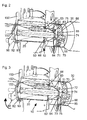
- FIGS. 1 to 3 show various views of a mixing device 10, which has a burner tube 20, the of a blower 120 combustion air is supplied.
- the burner tube 20 is followed axially by a flame tube 30. It is in principle possible that the flame tube 30 attaches directly to the burner tube 20 and thus is partially overlapping, with any conceivable connection between the burner tube 20 and the flame tube 30 is possible.
- the burner tube 20 terminates at an inner side of a housing 110 of a burner 100, wherein the flame tube 30 is attached outside the housing 110 of the burner 100 by means of an adapter ring 80.
- the flame tube 30 has an enlarged diameter relative to the burner tube 20.
- the mixing device 10 has a longitudinal axis 1.
- the longitudinal axis 1 of the mixing device substantially corresponds to the longitudinal axis of the burner tube 20 and the longitudinal axis of the flame tube 30.
- the adapter ring 80 with includes.
- the adapter ring 80 has an end region 81 facing the burner tube 20 and an end region 82 facing the flame tube 30, wherein the adapter ring 80 is attached with its end region 81 to the outside of the housing 110 and has an overlap with the flame tube 30 in its end region 82 and with the flame tube 30 by means of a bayonet closure connected is.
- a connection can also be made by pressing or welding.
- recirculation openings 85 are arranged, depending on the connection between the burner tube 20 and the flame tube 30 in an end portion of the burner tube 20 facing the flame tube 30, in an end region of the flame tube 30 facing the burner tube and / or in the adapter ring 80 may be arranged, wherein they are arranged in the present case in the adapter ring 80.
- a cutting disk 50 is used, whose outer diameter substantially corresponds to the inner diameter of the burner tube 20 and which has a central opening 51 through which a nozzle coaxially 40 is guided with a fuel nozzle 42.
- Coaxially disposed on the cutting disk 50 is an air nozzle 60, which is designed such that it faces the burner pipe 20 has an inlet opening 61 and tapers from the diameter of the inlet opening 61 to an outlet opening 63, which faces the flame tube 30.
- the air nozzle 60 has at its inlet opening 61 a flange 64, which is formed in the present example by the cutting disk 50.
- the air nozzle 60 has a substantially conical shape, which may also have a curved outer shell or a frustoconical outer shell. It is also possible that the air nozzle 60 initially has a cylindrical portion, which is followed by a tapered portion.
- the housing 110 of the burner 100 has an opening 112 through which the air nozzle 60 is passed, wherein the air nozzle 60, the housing 110 of the burner 100 by means of the flange 62, d. H. seals by means of the cutting disc 50 combustion air side.
- a seal 66 is disposed between the flange 62 and the inner wall of the housing 110, wherein the flange 62 has an outer diameter which is greater than the diameter of the opening 112 of the housing 110 and the air nozzle 60 at its burner tube end has an outer periphery, the essentially corresponds to the diameter of the opening 112.
- the flange 62 and the seal 66 are pressed from the inside against the inner wall of the housing 110, for example, spring-loaded.
- the cutting disk 50 has swirl openings 53 which offset the air flowing through the burner pipe 20 into the air nozzle 60 into rotation about the longitudinal axis 1 of the mixing device 10.
- a nozzle 40 is axially inserted, via which the fuel, for example, both gaseous and liquid fuel, is supplied.
- the fuel for example, both gaseous and liquid fuel
- the fuel exhausts through the fuel nozzle 42 from.
- the supplied gaseous or liquid fuels may be fossil, synthetic or biogenic fuels.
- the fuel nozzle 42 may be formed as a fuel nozzle for liquid fuels or as a gas nozzle. It is also possible that the nozzle 40 is formed with a coaxial gas line with an annular gas nozzle in the region of the fuel nozzle 42 for liquid fuels, for example, for oil, so that the burner 100 can be operated in two-stage operation with gas and liquid fuel.
- the mixing device 10 has two ignition electrodes 55 of a transistor coil ignition, with which the atomized fuel is ignited.
- the ignition electrodes 55 are angled at their free ends such that their free ends are located at a smaller distance than their non-angled ends, wherein the free ends are bent substantially in front of the outlet openings 63 of the air nozzle 60. Between the two ends of the ignition electrodes 55, the flame is ignited.
- the fuel nozzle 42 is arranged such that the flame extends in the flame tube 30 in front of the outlet opening 63 of the air nozzle 60.
- the externally mounted ignition electrodes 55 can be changed without disassembling the burner 100.
- the ignition electrodes 55 can additionally be used as ionization electrodes in ionization current flame monitoring. If no ionization monitoring is used, an optical flame monitoring and / or a direct measurement of the combustion quality takes place with the aid of a CO or 02 sensor.
- the mixing device 10 has recirculation means 70, which are arranged axially fixed within the mixing device 10 and with which it is possible to adjust a passage cross-section 86 of the recirculation openings 85 adjustable.
- the recirculation means 70 are in particular formed as an annular element with a peripheral wall 71, which in an alternative embodiment may have a bottom 72 so as to form a pot-shaped element which is open, for example, in the direction of the flame tube 30.
- the outer diameter of the peripheral wall 71 of the recirculation means 70 corresponds substantially to the inner diameter of the adapter ring 80, wherein optionally a game is provided, but the adapter ring 80 as a whole Guide tube for the recirculation means 70 is used.
- a central opening 73 is arranged, which is upstream of the outlet opening 73 of the air nozzle 60 and the nozzle 40 with the fuel nozzle 42.
- the ignition electrodes 55 are guided through two further openings of the bottom 72 of the recirculation means 70.
- the central opening 73 of the bottom 72 of the recirculation means 70 may be formed as a nozzle-shaped outlet opening 74.
- openings 75 are arranged in the peripheral wall 71 of the recirculation means 70 .
- Both the recirculation openings 85 and the openings 75 are in particular designed as slits inclined against the longitudinal axis 1 of the mixing device 10, wherein preferably the recirculation openings 85 and the openings 75 substantially coincide in their shape and inclination.
- the recirculation means 70 are fixed axially in that they abut against the burner tube 20 facing the end of the flame tube 30, which is overlapped on the inside of the adapter ring 80, abutting.
- the recirculation means 70 are preferably further axially fixed by the fact that the central opening 73 of the bottom 72 is arranged fixed to the air nozzle 60, for example the outlet opening 63 of the air nozzle 60.
- a flange 64 is arranged, which is fixed to the bottom 72 of the recirculation means 70, for example, welded or screwed.
- the bottom 72 of the recirculation means 70 can serve in particular as a heat seal between the burner tube 20 and the flame tube 30.
- an insulation may be arranged between the recirculation means 70 and the outside of the housing 110 of the burner 100 in order to reduce the heat load on the burner chamber.
- the recirculation means 70 are arranged around their longitudinal axis, which in particular coincides with the longitudinal axis l of the mixing device 10 rotatably within the mixing device 10 and formed to vary the passage cross-section 86 of the recirculation openings 85 when rotating about its longitudinal axis.
- the openings 75 are arranged either in alignment with the recirculation openings 85 and thus release the complete passage cross section 86 of the recirculation openings 85 or if the peripheral wall 71 of the recirculation means 70 continues to recirculate the recirculation openings 85 at least partially or further completely cover and thus the passage cross-section 86 vary up to the complete closure of the recirculation 85.
- the rotation of the recirculation means 70 is effected in particular by means of an operating element guided within the mixing device 10.
- the actuating element is formed by the air nozzle, which is connected to the recirculation means 70 axially and rotationally fixed, and a rotatably mounted on the air nozzle 60 holder 43 for the nozzle 40.
- the holder 43 holds the nozzle assembly 40 coaxially in the burner tube 20 and the air nozzle 60.
- the holder 43 has in particular a first element 43a and a second element 43b, which by means of a dog clutch 44 (see, in particular FIG. 6 ) are rotatably connected to each other.
- the second element 43b is arranged upstream of the cutting disk 50, which is connected to the air nozzle 60, while the first element 43a is arranged upstream of the second element 43b and upstream connected to an actuating plate 90, by means of which the holder 43 in particular in the housing 110 of the burner 100 is attached.
- the actuator plate 90 in particular allows an airtight seal of the housing 110 of the burner 100 and is preferably arranged rotatably mounted in the housing 110.
- the rotational path of the actuating plate 90 is preferably limited by means arranged in the actuating plate 90 groove 92 which is formed as an arc segment, and guided in the groove 92 pin 93 which is non-rotatably disposed, for example, on the outer wall of the housing 110 to clearly recognizable from the outside to be able to adjust the positions in which the recirculation means 70, the recirculation openings 80 either fully open or close completely.
- a rotation of the actuator plate 90 can be done either manually or automatically, in particular automatically with the aid of a controller.
- a spring 45 in particular a helical spring 45 is arranged (cf. FIG. 6 ), which is stretched between corresponding circumferential projections on the first element 43a and the second element 43b and thus a pressing of the second element 43b including the arranged thereon
- Cutting disc 50 causes the inner wall of the housing 110, so that with the aid of the arranged between the cutting disc 50 and the inner wall of the housing 110 seal 66, a seal of the opening 112, through which the air nozzle 60 of the mixing device 10 is performed.
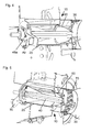
- FIGS. 4 and 5 show perspective, partially sectional views of the mixing device 10 according to the FIGS. 1 to 3 , wherein the air nozzle 60 burner tube side is not completed by the cutting disk 50.
- the sealing between the interior of the burner tube 20 and the interior of the flame tube 30 preferably takes place through the bottom 72 of the recirculation means 70.
- the cutting disc 50 can be dispensed with, in particular, when already twisted air is introduced into the burner tube 20.
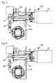
- FIGS. 7 to 10 show various views of the burner 100 with the mixing device 10 according to the FIGS. 1 to 3 from which it can be seen that, in one embodiment, the nozzle assembly 40, including the fuel nozzle 42, is disposed axially displaceable in the mixing device 10.
- the nozzle assembly 40 in a first position, in which the fuel nozzle 42 in the outlet opening 63 of the air nozzle 60 is during FIG. 8 shows the position of the nozzle block 40, in which the fuel nozzle 42 axially upstream from the outlet opening 63 of the air nozzle 60 is located.
- a spindle 47 is arranged at the upstream end of the nozzle block 40, which is guided by an adjusting nut 48.
- the fuel nozzle 42 is either turned into the mixing device 10 or out of the mixing device 10.
- the spindle 47 is led out of the housing 110 of the burner 100 at the upstream end of the burner tube, in particular an axial movement of the nozzle block 40 can also take place during the operation of the burner 100.
- the adjusting nut 48 in particular the axial position of the nozzle block 40 is infinitely adjustable.
- locking means so that at the desired position of the adjusting nut 48, a fixing of the adjusting nut 48 can be made to prevent accidental adjustment of the adjusting nut 48.
- a locking device 49 may be provided, which allows a locking such that the adjusting nut 48 is fixed in the axial direction to prevent complete axial withdrawal of the spindle 47.
- the spindle 47 including the nozzle block 40 and the fuel nozzle 42 arranged thereon can be pulled axially out of the mixing device 10, so that a simple exchange of the fuel nozzle 42 can take place in this manner.
- the locking device 49 is designed in particular as a plate 49a displaceable transversely to the longitudinal axis 1 of the mixing device 10, with a keyhole-like opening 49b (cf. FIGS. 4 .
- the nozzle 40 is in particular manually or automatically axially displaceable, in particular rule-based displaced with automated displacement.
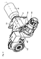
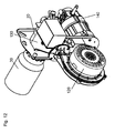
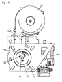
- FIGS. 11 to 15 show various components of the burner 100 with the mixing device 10, the blower 120 and a fuel pump 140th
- the fan 120 generates an airflow along a first direction x (see in particular FIG Figures 11 and 16 ), which is introduced by means of a connecting channel 130 in the burner tube 20 of the mixing device 10. Based on FIGS. 16 to 18 the design of the connecting channel 130 is explained in more detail, which is basically independent of the specific embodiment of the mixing device 10.
- the fan 120 generates an air flow in the first direction x, in which the air flows into the connecting channel 130, wherein the connecting channel 130 deflects the air in a second direction y, which is in particular perpendicular to the first direction x.
- the second direction y corresponds to the longitudinal axis 1 of the mixing device 10, so that the connecting channel 130 ensures that the air flows in the direction of the longitudinal axis 1 into the mixing device 10, but the fan 120 does not have to be arranged in extension of the longitudinal axis 1, where the thermal load is high, but can be arranged offset to the longitudinal axis 1, where the thermal load is lower.
- the connecting channel 130 In the first direction x, the connecting channel 130 widened in a wedge-shaped manner so as to already give the air flow a velocity component in the second direction y.
- the connecting channel 130 is in particular designed such that it has means which direct the air flowing in the first direction x into a circular flow around the second direction y. In this way, a swirl of the air flow is achieved already in the connecting channel 130, which favors the operation of the mixing device 10 in that a better turbulence between the incoming air and the sprayed fuel takes place, so that a more stable flame can be achieved in this way ,
- the connecting channel 130 has a pipe section 132, the longitudinal axis of which runs parallel to the second direction y and thus parallel to the longitudinal axis 1 of the mixing device 10 and which in particular coincides at least in sections with the burner pipe 20.
- the pipe section 132 has at least one, in the present case two diametrically opposite inlet openings 134. Through one of the two inflow openings 134, air flowing along the first direction x can flow tangentially into the pipe section 132. Through the diametrically opposite inlet opening 134 also flows air tangentially into the pipe section 132, but after deflection by 180 ° from the first direction x.
- direct air is introduced tangentially into the burner tube 20 by means of the connecting channel 130, wherein a circular flow is generated about the longitudinal axis 1 of the mixing device 10 and thus already supplied through the burner tube 20 twisted air of the air nozzle 60, so that optionally the separating disk 50 with swirl openings 53 can be omitted, alternatively the air is twisted further in the direction of the longitudinal axis 1 of the mixing device 10 by the swirl openings 53 of the separating disk 50.
- the direction of the swirl openings 53 corresponds in particular to the direction of the circular flow about the longitudinal axis 1 of the mixing device 10, to the air flow disturb as little as possible.
- the inclination of the recirculation opening 85 and the openings 75 of the recirculation means 70 correspond in particular to the swirl direction of the incoming air in order to disturb the flow as little as possible.
- the diversion of the air flowing from the blower 120 into the inflow opening 134 takes place, in particular, by means of an air guide plate 138, which divides the connecting channel 130 into two air ducts, of which one deflects air onto the first inflow opening 134 and the other air diverts through 180 ° into the second Inlet opening 134 passes, in order to be able to introduce air through both inlet openings 134 tangentially into the pipe section 132 in this way.
- the air guide plate 138 is adjustable in its position within the connecting channel 130, for example by means of a screw 139 in order to vary the amount of air flowing through the two inlet openings 134.
- a passage cross-section 135 of the inflow openings 134 is variably adjustable.
- the means are designed as a tube 136, which rests with its outer wall on the inner wall of the pipe section 132 and / or the inner wall of the air baffle 138.
- the tube 136 has two diametrically arranged openings 137 which are formed in particular as slots in the direction of the longitudinal axis 1 of the mixing device 10, wherein the tube 136 is arranged rotatably mounted about the longitudinal axis l, so that depending on the rotation and position of the tube 136 and the openings 137 relative to the inlet openings 134, the inflow openings 134 more or less open and thus the passage cross-section 135 of the inflow openings 134 is varied.
- the rotation of the tube 136 is effected in particular by means of an actuating lever 150 (cf. Fig.
- the actuating lever 150 has a groove 152, in which a pin 153 is guided, whereby a limitation of the rotational travel of the actuating lever 150 is carried out, so that even without opening the burner housing to recognize whether the inlet openings 134 just a maximum or minimum or a have between the extreme positions located passage cross-section.
- the air flow in the direction of the longitudinal axis 1 of the mixing device 10 is further facilitated by the fact that in the pipe section 132, in particular in the burner tube 20, a truncated cone is arranged, the tapered portion facing in the direction of the mixing device 10 or the flame tube 30, wherein in the present case second element 43b of the holder 43 of the nozzle block 40 is formed as a truncated cone-like element.
- connection channel 130 shows the FIGS. 19 and 20 . It is possible, as in the FIGS. 19 and 20 2, the air guide plate 138 arranged in the connection channel 130 is omitted, so that the air flowing out of the blower 120 flows partially into the first inlet opening 134 and partially only on the outside of the burner tube 20 into the diametrically opposite inlet opening 134.
- a baffle 131 may be tangentially disposed on the tube 136, that extends in particular through the first inflow opening 134 into the connecting channel 130 and favors a division of the air flow. In this case, the baffle 131 is also upon rotation of the tube 136 rotated, so that in this way also a variation of the passage cross-section of the inflow opening 134 can take place.
- the fan 120 is preferably infinitely variable in its speed. Furthermore, the amount of fuel, which is supplied via the fuel nozzle 42 of the mixing device 10, also variable continuously.
- the burner 100 with the mixing device 10, the blower 110 and the connecting channel 130 arranged between them enables a low-emission, efficient combustion of liquid or gaseous fuels. Due to the described geometry of the connecting channel 130, the pressure loss of the incoming combustion air is minimized and the blower pressure is used primarily for mixing combustion air and fuel and to overcome the exhaust-side resistances in the heat generator and in the exhaust system.
- the geometry of the connecting channel 130 further causes an increase in the static pressure of the cross-sectional widening of the air ducts in the transition to the burner tube 20, which stabilizes the flame even with pressure fluctuations in the exhaust system.
- soot formation on the mixing head and the ignition electrodes 55 is prevented.
- the good mixing of combustion air, exhaust gases and fuel allows a reduction of the injection pressure, in particular of fuel oil, to less than 4 bar. This allows a reduction of the burner power to less than 7 kW when commercial fuel nozzles 42 are used.
- the system is also suitable for use in larger power ranges of more than 150 kW, where so far the exponentially increasing fan power limited the use of Blaubrandsystemen with spin stabilized flame.
- the optimally stabilized flame makes the system particularly suitable for the use of condensing heat exchangers and boilers with high exhaust-side resistances.
- the sealing of the air nozzle 60 to the flame tube 30 and combustion chamber prevents unwanted, undefined false air flow. This conditional soot formation and undesirable pressure loss can be avoided.
- the present burner 100 thus has, in particular, a housing geometry which, by appropriate guidance of the combustion air, causes it to rotate in front of the air nozzle 60 by tangential inflow into the burner tube 20. Further, the recirculating exhaust gases are supplied via obliquely arranged, oriented in the twist direction recirculation openings 85 of the combustion zone.
- the fuel nozzle 42 can be moved axially to the fixed air nozzle 60, whereby the resulting Heilausströmquerites is variable.
- the outflowing air velocity, the air volume and the air pressure are thus changeable.
- a variable speed fan 120 are those required for combustion Air volume, air speed and air pressure adjustable according to a characteristic curve. If, in addition, the fuel quantity is varied, for example by means of a modulating fuel pump 140 or a modulating fuel valve, a modulating combustion mode of the burner 100 is possible in addition to single-stage or multistage operation.
Landscapes
- Engineering & Computer Science (AREA)
- Chemical & Material Sciences (AREA)
- Combustion & Propulsion (AREA)
- Mechanical Engineering (AREA)
- General Engineering & Computer Science (AREA)
- Gas Burners (AREA)
Abstract
Description
- Die Erfindung betrifft eine Mischeinrichtung für einen Brenner gemäß dem Oberbegriff des Patentanspruchs 1.
- Bekannt sind Mischeinrichtungen für einen Brenner, die ein Brennerrohr, ein sich an das Brennerrohr anschließendes Flammrohr und einen in dem Brennerrohr angeordneten Düsenstock aufweisen, wobei koaxial in dem Brennerrohr eine Luftdüse angeordnet ist, die sich in das Flammrohr hinein erstreckt und Verbrennungsluft aus dem Brennerrohr in das Flammrohr führt, wobei eine Halterung vorgesehen ist, die den Düsenstock koaxial in dem Brennerrohr und der Luftdüse hält. Oft sind in einem Übergangsbereich zwischen dem Brennerrohr und dem Flammrohr Rezirkulationsöffnungen angeordnet sind. Derartige Brenner mit Rezirkulations-Mischeinrichtungen werden als Blaubrenner bezeichnet. Blaubrenner erreichen dank ihrer rauchgasgekühlten Flamme niedrigste Schadstoffwerte und überwinden mühelos hohe Feuerraumwiderstände.
- Bekannt sind dabei Brenner mit axial verschiebbarem Mischkopf, d. h. axial verschiebbarem Düsenstock und Luftdüse. Der Mischkopf ist im Brennerrohr verschiebbar, um den Durchtrittsquerschnitt der Rezirkulationsöffnungen, durch welche Verbrennungsgase aus dem Feuerraum in die Flamme zirkulieren, einstellbar zu verändern. Eine derartige Mischeinrichtung zeigt beispielsweise die
EP 0 777 084 B1 . - Weiterhin bekannt sind Brenner mit einem im Brennerrohr fixiert angeordneten Mischkopf. Eine axial fixierte Luftdüse weist den Vorteil auf, dass kaum Leckluft an ihrem Außenrand entlang strömen kann, welche zu Verrußung des Mischkopfs und der Zündelektroden führen kann. Allerdings weist der fixiert angeordnete Mischkopf den Nachteil auf, dass keine Variation der Luftmenge und/oder Luftgeschwindigkeit erfolgen kann.
- Die Aufgabe der Erfindung besteht darin, eine Mischeinrichtung für einen Brenner bereitzustellen, die variabler einsetzbar und benutzerfreundlicher ist.
- Die Aufgabe der Erfindung wird gelöst durch eine Mischeinrichtung für einen Brenner mit den Merkmalen des Patentanspruchs 1.
- Vorteilhafte Ausgestaltungen und Weiterbildungen der Erfindung sind in den Unteransprüchen angegeben.
- Die erfindungsgemäße Mischeinrichtung für einen Brenner, die ein Brennerrohr, ein sich an das Brennerrohr anschließendes Flammrohr und einen in dem Brennerrohr angeordneten Düsenstock aufweist, wobei koaxial in dem Brennerrohr eine Luftdüse angeordnet ist, die sich in das Flammrohr hinein erstreckt und Verbrennungsluft aus dem Brennerrohr in das Flammrohr führt und wobei eine Halterung vorgesehen ist, die den Düsenstock koaxial in dem Brennerrohr und der Luftdüse hält, weist zusätzlich eine Luftdüse auf, welche axial fixiert in dem Brennerrohr angeordnet, wobei der Düsenstock axial verschiebbar in dem Brennerrohr angeordnet ist. Auf diese Weise wird eine Relativbewegung zwischen dem Düsenstock und einer darin angeordneten Brennstoffdüse einerseits sowie der Luftdüse andererseits erzielt, durch welche der entstehende Luftauströmquerschnitt veränderbar ist. Dabei muss jedoch auf den Vorteil einer axial fixierten Luftdüse nicht verzichtet werden. Insbesondere sind somit die ausströmende Luftgeschwindigkeit, die Luftmenge und der Luftdruck veränderbar.
- In Verbindung mit einem drehzahlgeregelten Gebläse des Brenners sind die zur Verbrennung erforderlichen Luftmenge, die Luftgeschwindigkeit und der Luftdruck nach einer Kennlinie anpassbar.
- Vorzugsweise weist die Mischeinrichtung eine den Innenraum des Brennerrohrs liegenden Innenraum des Flammrohres abschließenden Trennscheibe auf, welche eine zentrische Öffnung aufweist, an welcher koaxial die Luftdüse angeordnet ist, die sich in das Rohr hinein erstreckt und Verbrennungsluft aus dem Brennerrohr in das Flammrohr führt. Besonders bevorzugt weist die Trennscheibe Drallöffnungen auf, um die durch das Brennerrohr strömende Luft bei Eintritt in die Luftdüse zu verdrallen. Verdrallte Luft verbessert die Vermischung der Verbrennungsluft, der rezirkulierenden heißen Abgase und des eingedüsten Brennstoffsprays.
- Vorzugsweise ist der Düsenstock mittels einer Spindel axial verschiebbar, was konstruktiv besonders einfach zu realisieren ist.
- Gemäß einer besonders bevorzugten Ausführungsform ist die Mischeinrichtung in einem Gehäuse eines Brenners angeordnet und die Spindel aus dem Gehäuse des Brenners herausgeführt, um ein axiales Verschieben des Düsenstocks während des Betriebs des Brenners zu ermöglichen.
- Der Düsenstock kann dabei entweder manuell oder auch automatisiert, insbesondere geregelt, axial verschiebbar ausgebildet sein.
- Vorzugsweise weist die Mischeinrichtung eine Halterung auf, die den Düsenstock koaxial in dem Brennerrohr und der Luftdüse hält, wobei die Halterung mittels einer Befestigungsplatte in dem Gehäuse des Brenners befestigt ist. Vorzugsweise ermöglicht dabei die Betätigungsplatte eine luftdichte Abdeckung.
- Besonders bevorzugt ist die Betätigungsplatte drehbar gelagert in dem Gehäuse angeordnet, um auf diese Weise eine Drehung der Halterung zu ermöglichen. Vorzugsweise ist die Betätigungsplatte manuell oder automatisiert, insbesondere geregelt, verdrehbar.
- Gemäß einer vorteilhaften Ausführungsform der Erfindung ist an der Spindel eine Verriegelungsvorrichtung angeordnet, um zu verhindern, dass die Spindel mit daran angeordnetem Düsenstock ohne weiteres aus dem Brennerrohr herausgezogen werden kann, jedoch auch bei Lösen der Verriegelungsvorrichtung zu ermöglichen, dass der Düsenstock aus dem Brennerrohr herausgezogen werden kann, um ein einfaches Wechseln der Brennstoffdüse zu ermöglichen.
- Ein erfindungsgemäßer Brenner weist eine erfindungsgemäße Mischeinrichtung auf. Besonders bevorzugt weist der Brenner ein Gebläse auf, wobei die Drehzahl des Gebläses stufenlos veränderbar ist, um die zur Verbrennung erforderliche Luftmenge, die Luftgeschwindigkeit und der Luftdruck, in Kombination mit der axial zur Luftdüse verschiebbarem, an dem Düsenstock angeordneten Brennstoffdüse, variieren zu können.
- Besonders bevorzugt weist die Mischeinrichtung einen Düsenstock mit einer Düse auf, über welche der Brennstoff zugeführt wird, wobei die Menge des Brennstoffs stufenlos veränderbar, beispielsweise mit Hilfe einer entsprechenden Brennstoffpumpe oder eines entsprechenden Brennstoffventils, ist. Insbesondere in Kombination mit dem drehzahlgeregelten Gebläse und der axial verschiebbaren Düsenstock, ist neben einem ein- oder mehrstufigen Betrieb des Brenners auch eine modulierende Betriebsweise des Brenners möglich.
- Die Erfindung wird anhand der nachfolgenden Figuren ausführlich erläutert. Es zeigen:
- Figur 1
- einen Schnitt durch einen Teil eines Brenners mit einer Mischeinrichtung gemäß einem ersten Ausführungsbeispiel der Erfindung,
- Figur 2
- eine teilweise geschnittene perspektivische An- sicht der Mischeinrichtung gemäß
Figur 1 mit Re- zirkulationsmitteln in einer ersten Position, - Figur 3
- die Mischeinrichtung gemäß
Figur 2 mit den Re- zirkulationsmitteln in einer zweiten Position, - Figur 4
- eine teilweise geschnittene perspektivische An- sicht eines zweiten Ausführungsbeispieles einer Mischeinrichtung,
- Figur 5
- die Mischeinrichtung gemäß
Figur 4 in einer wei- teren teilweise geschnittenen perspektivischen Ansicht, - Figur 6
- eine perspektivische Ansicht einer Klauenkupp- lung einer Halterung der Mischeinrichtung gemäß
Figur 2 , - Figur 7
- eine teilweise geschnittene Darstellung der Tei- le eines Brenners gemäß
Figur 1 mit einem Düsen- stock in einer ersten Position, - Figur 8
- die Darstellung gemäß
Figur 7 mit dem Düsenstock in einer zweiten Position, - Figur 9
- den Brenner gemäß
Figur 1 in perspektivischer Darstellung mit teilweise geschnittener Misch- einrichtung, - Figur 10
- eine weitere perspektivische Ansicht mit teil- weiser geschnittener Mischeinrichtung gemäß Fi- gur 9,
- Figur 11
- eine perspektivische Ansicht der Komponenten des Brenners gemäß
Figur 1 , - Figur 12
- eine weiteren perspektivische Darstellung der Komponenten des Brenners gemäß
Figur 1 , - Figur 13
- eine Seitenansicht der Komponenten des Brenners gemäß
Figur 1 , - Figur 14
- eine weitere Seitenansicht der Komponenten des Brenners gemäß
Figur 1 , - Figur 15
- eine weitere Seitenansicht der Komponenten des Brenners gemäß
Figur 1 , - Figur 16
- die Seitenansicht gemäß
Figur 15 mit Blick in den Verbindungskanal zwischen einem Gebläse und der Mischeinrichtung, - Figur 17
- eine teilweise geschnittene Darstellung der Kom- ponenten des Brenners mit Blick in den Verbin- dungskanal zwischen dem Gebläse und der Misch- einrichtung mit einem Rohr zur Variation des Durchtrittsquerschnitts von Einströmöffnungen in einer ersten Position,
- Figur 18
- die teilweise geschnittene Darstellung gemäß Fi- gur 17 mit dem Rohr zur Variation des Durch- trittsquerschnitts der Einströmöffnungen in ei- ner zweiten Position,
- Figur 19
- eine teilweise geschnittene Darstellung der Kom- ponenten des Brenners mit Blick in den Verbin- dungskanal zwischen dem Gebläse und der Misch- einrichtung mit einer alternativen Ausführungs- form eines Rohrs zur Variation des Durchtritt- squerschnitts von Einströmöffnungen in einer ersten Position und
- Figur 20
- die teilweise geschnittene Darstellung gemäß Fi- gur 20 mit dem Rohr zur Variation des Durch- trittsquerschnitts der Einströmöffnungen in ei- ner zweiten Position.
- In allen Figuren sind gleiche Teile mit gleichen Bezugsziffern bezeichnet, wobei zur besseren Übersicht nicht sämtliche Figuren sämtliche Bezugsziffern zeigen.
- Die
Figuren 1 bis 3 zeigen verschiedene Ansichten einer Mischeinrichtung 10, welche ein Brennerrohr 20 aufweist, dem von einem Gebläse 120 Verbrennungsluft zugeführt wird. An das Brennerrohr 20 schließt sich axial ein Flammrohr 30 an. Es ist grundsätzlich möglich, dass das Flammrohr 30 direkt an dem Brennerrohr 20 ansetzt und somit teilweise überlappend ausgebildet ist, wobei jede denkbare Verbindung zwischen dem Brennerrohr 20 und dem Flammrohr 30 möglich ist. In der vorliegenden Ausführungsform endet das Brennerrohr 20 an einer Innenseite eines Gehäuses 110 eines Brenners 100, wobei das Flammrohr 30 außerhalb des Gehäuses 110 des Brenners 100 mit Hilfe eines Adapterrings 80 angesetzt ist. Das Flammrohr 30 weist gegenüber dem Brennerrohr 20 einen erweiterten Durchmesser auf. Es ist jedoch auch möglich, dass das Flammrohr sich im Durchmesser gegenüber dem Brennerrohr 20 verjüngt oder dass das Brennerrohr 20 und das Flammrohr 30 im Wesentlichen identische Durchmesser aufweisen. Die Mischeinrichtung 10 weist eine Längsachse 1 auf. Die Längsachse 1 der Mischeinrichtung entspricht im wesentlichen der Längsachse des Brennerrohres 20 und der Längsachse des Flammrohres 30. - Zwischen dem Brennerrohr 20 und dem Flammrohr 30 ist ein Übergangsbereich gebildet, der bei überlappender Anordnung des Brennerrohrs 20 und des Flammrohrs 30 die einander zugewandten Endbereiche des Brennerrohrs 20 bzw. des Flammrohrs 30 umfasst und gegebenenfalls wie vorliegend bei Verwendung eines Adapterrings 80 den Adapterring 80 mit einschließt.
- Der Adapterring 80 weist einem dem Brennerrohr 20 zugewandten Endbereich 81 und einem dem Flammrohr 30 zugewandten Endbereich 82 auf, wobei der Adapterring 80 mit seinem Endbereich 81 auf die Außenseite des Gehäuses 110 angesetzt ist und in seinem Endbereich 82 einen Überlapp mit dem Flammrohr 30 aufweist und mit dem Flammrohr 30 mittels eines Bajonettverschlusses verbunden ist. Alternativ kann eine Verbindung auch durch Verpressen oder Verschweißen erfolgen.
- In dem Übergangsbereich von Brennerrohr 20 und Flammrohr 30 sind Rezirkulationsöffnungen 85 angeordnet, die je nach Verbindung zwischen dem Brennerrohr 20 und dem Flammrohr 30 in einem dem Flammrohr 30 zugewandten Endbereich des Brennerrohrs 20, in einem dem Brennerrohr zugewandten Endbereich des Flammrohrs 30 und/oder in dem Adapterring 80 angeordnet sein können, wobei sie im vorliegenden Fall in dem Adapterring 80 angeordnet sind. Durch die Rezirkulationsöffnungen 85 können aus der Brennkammer Verbrennungsgase in die Flamme der Mischeinrichtung 10 zurückgeführt werden.
- In das Brennerrohr 20 ist eine Trennscheibe 50 eingesetzt, deren Außendurchmesser im Wesentlichen dem Innendurchmesser des Brennerrohrs 20 entspricht und welche eine zentrische Öffnung 51 aufweist, durch welche koaxial ein Düsenstock 40 mit einer Brennstoffdüse 42 geführt ist. An der Trennscheibe 50 ist koaxial eine Luftdüse 60 angeordnet, welche derart ausgebildet ist, dass sie dem Brennerrohr 20 zugewandt eine Eintrittsöffnung 61 aufweist und sich ausgehend von dem Durchmesser der Eintrittsöffnung 61 bis zu einer Austrittsöffnung 63 verjüngt, welche dem Flammrohr 30 zugewandt ist. Die Luftdüse 60 weist an ihrer Eintrittsöffnung 61 einen Flansch 64 auf, der im vorliegenden Beispiel durch die Trennscheibe 50 gebildet ist. Die Luftdüse 60 weist eine im Wesentlichen konische Gestalt auf, welche auch einen gewölbten Außenmantel oder einen kegelstumpfartigen Außenmantel aufweisen kann. Es ist auch möglich, dass die Luftdüse 60 zunächst einen zylindrischen Abschnitt aufweist, an welchen sich ein verjüngender Abschnitt anschließt.
- Das Gehäuse 110 des Brenners 100 weist eine Öffnung 112 auf, durch welche die Luftdüse 60 hindurchgeführt ist, wobei die Luftdüse 60 das Gehäuse 110 des Brenners 100 mittels des Flansches 62, d. h. mittels der Trennscheibe 50 verbrennungsluftseitig abdichtet. Dazu ist zwischen dem Flansch 62 und der Innenwand des Gehäuses 110 eine Dichtung 66 angeordnet, wobei der Flansch 62 einen Außendurchmesser aufweist, der größer ist als der Durchmesser der Öffnung 112 des Gehäuses 110 und die Luftdüse 60 an ihrem brennerrohrseitigen Ende einen Außenumfang aufweist, der im Wesentlichen dem Durchmesser der Öffnung 112 entspricht. Der Flansch 62 und die Dichtung 66 werden von innen gegen die Innenwand des Gehäuses 110 gedrückt, beispielsweise federbelastet.
- Die Trennscheibe 50 weist Drallöffnungen 53 auf, welche die durch das Brennerrohr 20 in die Luftdüse 60 strömende Luft in Rotation um die Längsachse l der Mischeinrichtung 10 versetzt.
- In die Luftdüse 60 ist axial ein Düsenstock 40 eingesetzt, über den der Brennstoff, beispielsweise sowohl gasförmiger als auch flüssiger Brennstoff, zugeführt wird. Am vorderen Ende des Düsenstockes 40 tritt der Brennstoff zerstäubt über die Brennstoffdüse 42 aus. Die zugeführten gasförmigen oder flüssigen Brennstoffe können fossile, synthetische oder biogene Brennstoffe sein.
- Die Brennstoffdüse 42 kann als Brennstoffdüse für flüssige Brennstoffe oder als Gasdüse ausgebildet sein. Es ist auch möglich, dass der Düsenstock 40 mit einer koaxialen Gasleitung mit einer ringförmiger Gasdüse im Bereich der Brennstoffdüse 42 für flüssige Brennstoffe, beispielsweise für Öl, ausgebildet ist, so dass der Brenner 100 im Zweistoffbetrieb mit Gas und flüssigem Brennstoff betrieben werden kann.
- Die Mischeinrichtung 10 weist zwei Zündelektroden 55 einer Transistorspulenzündung auf, mit welchen der zerstäubte Brennstoff gezündet wird. Die Zündelektroden 55 sind an ihren freien Enden derart abgewinkelt, dass ihre freien Enden in einem kleineren Abstand liegen als ihre nicht abgewinkelten Enden, wobei die freien Enden im Wesentlichen vor die Austrittsöffnungen 63 der Luftdüse 60 gebogen sind. Zwischen den beiden Enden der Zündelektroden 55 wird die Flamme gezündet. Die Brennstoffdüse 42 ist dabei derart angeordnet, dass sich die Flamme in dem Flammrohr 30 vor der Austrittsöffnung 63 der Luftdüse 60 erstreckt. Die extern angebrachten Zündelektroden 55 können gewechselt werden, ohne den Brenner 100 zu demontieren. Die Zündelektroden 55 können bei einer Ionisationsstrom-Flammenüberwachung zusätzlich als Ionisationselektroden verwendet werden. Wird keine Ionisationsüberwachung eingesetzt, erfolgt eine optische Flammenüberwachung und/oder eine direkte Messung der Verbrennungsgüte mit Hilfe eines CO- oder 02-Sensors.
- Die Mischeinrichtung 10 weist Rezirkulationsmittel 70 auf, welche axial fixiert innerhalb der Mischeinrichtung 10 angeordnet sind und mit welchen es möglich ist, einen Durchtrittsquerschnitt 86 der Rezirkulationsöffnungen 85 einstellbar zu verändern. Die Rezirkulationsmittel 70 sind insbesondere als ringförmiges Element mit einer Umfangswand 71 ausgebildet, welche in einer alternativen Ausführungsform einen Boden 72 aufweisen können, um derart ein topfförmiges Element zu bilden, das beispielsweise in Richtung auf das Flammrohr 30 offen ist. Der Außendurchmesser der Umfangswand 71 der Rezirkulationsmittel 70 entspricht dabei im Wesentlichen dem Innendurchmesser des Adapterrings 80, wobei gegebenenfalls ein Spiel vorgesehen ist, insgesamt der Adapterring 80 jedoch als Führungsrohr für die Rezirkulationsmittel 70 dient. Im Boden 72 der Rezirkulationsmittel 70 ist eine zentrische Öffnung 73 angeordnet, welche stromaufseitig vor der Austrittsöffnung 73 der Luftdüse 60 und dem Düsenstock 40 mit der Brennstoffdüse 42 liegt. Die Zündelektroden 55 sind durch zwei weitere Öffnungen des Bodens 72 der Rezirkulationsmittel 70 geführt. Die zentrische Öffnung 73 des Bodens 72 der Rezirkulationsmittel 70 kann als düsenförmige Austrittsöffnung 74 ausgebildet sein.
- In der Umfangswand 71 der Rezirkulationsmittel 70 sind Öffnungen 75 angeordnet. Sowohl die Rezirkulationsöffnungen 85 als auch die Öffnungen 75 sind insbesondere als gegen die Längsachse l der Mischeinrichtung 10 geneigte Schlitze ausgebildet, wobei vorzugsweise die Rezirkulationsöffnungen 85 und die Öffnungen 75 in ihrer Form und Neigung im Wesentlichen übereinstimmen. Die Rezirkulationsmittel 70 sind axial dadurch fixiert, dass sie an das dem Brennerrohr 20 zugewandte Ende des Flammrohres 30, welches innenliegend an dem Adapterring 80 überlappend eingeführt ist, auf Stoß anliegen. Die Rezirkulationsmittel 70 sind vorzugsweise weiterhin axial dadurch fixiert, dass die zentrische Öffnung 73 des Bodens 72 an der Luftdüse 60, beispielsweise der Austrittsöffnung 63 der Luftdüse 60 fixiert angeordnet ist. An der Austrittsöffnung 63 der Luftdüse 60 ist dazu insbesondere ein Flansch 64 angeordnet, welcher an dem Boden 72 der Rezirkulationsmittel 70 fixiert, beispielsweise verschweißt oder verschraubt ist.
- Der Boden 72 der Rezirkulationsmittel 70 kann insbesondere als Hitzeschott zwischen dem Brennerrohr 20 und dem Flammrohr 30 dienen. Zwischen den Rezirkulationsmitteln 70 und der Außenseite des Gehäuses 110 des Brenners 100 kann zusätzlich eine Isolierung angeordnet sein, um die Wärmebelastung des Brennerraums zu verringern.
- Die Rezirkulationsmittel 70 sind um ihre Längsachse, welche insbesondere mit der Längsachse l der Mischeinrichtung 10 übereinstimmt, drehbar innerhalb der Mischeinrichtung 10 angeordnet und ausgebildet, bei Drehung um ihre Längsachse den Durchtrittsquerschnitt 86 der Rezirkulationsöffnungen 85 zu variieren. Dies erfolgt insbesondere dadurch, dass bei Drehung der Rezirkulationsmittel 70 um ihre Längsachse die Öffnungen 75 entweder fluchtend zu den Rezirkulationsöffnungen 85 angeordnet sind und somit den vollständigen Durchtrittsquerschnitt 86 der Rezirkulationsöffnungen 85 freigeben oder bei Weiterdrehung die Umfangswand 71 der Rezirkulationsmittel 70 die Rezirkulationsöffnungen 85 zumindest teilweise oder vollständig überdecken und somit den Durchtrittsquerschnitt 86 variieren bis hin zur vollständigen Schließung der Rezirkulationsöffnungen 85.
- Die Drehung der Rezirkulationsmittel 70 erfolgt insbesondere mittels eines innerhalb der Mischeinrichtung 10 geführten Betätigungselements. Vorliegend ist das Betätigungselement durch die Luftdüse, welche mit den Rezirkulationsmitteln 70 axial und drehfest verbunden ist, und eine an der Luftdüse 60 drehfest angeordnete Halterung 43 für den Düsenstock 40 gebildet. Die Halterung 43 hält den Düsenstock 40 koaxial in dem Brennerrohr 20 und der Luftdüse 60. Die Halterung 43 weist insbesondere ein erstes Element 43a und ein zweites Element 43b auf, welche mittels einer Klauenkupplung 44 (vgl. insbesondere
Figur 6 ) drehfest miteinander verbunden sind. Das zweite Element 43b ist dabei stromaufseitig der Trennscheibe 50, welche mit der Luftdüse 60 verbunden ist, angeordnet, während das erste Element 43a stromauf des zweiten Elements 43b angeordnet ist und stromaufseitig mit einer Betätigungsplatte 90 verbunden ist, mittels welcher die Halterung 43 insbesondere im Gehäuse 110 des Brenners 100 befestigt ist. Die Betätigungsplatte 90 ermöglicht insbesondere eine luftdichte Abdichtung des Gehäuses 110 des Brenners 100 und ist vorzugsweise in dem Gehäuse 110 drehbar gelagert angeordnet. - Bei Drehen der Betätigungsplatte 90 wird somit das erste Element 43a der Halterung 43, über die Klauenkupplung 44 gleichzeitig das zweite Element 43b der Halterung 43 und darüber die Trennscheibe 50 sowie die daran angeordnete Luftdüse 60 einschließlich der an der Luftdüse 60 angeordneten Rezirkulationsmittel 70 verdreht, so dass auf dieser Art und Weise mit Hilfe der Betätigungsplatte 90 von außerhalb des Brenners 100 die Rezirkulationsmittel 70 verdreht werden können, um den Durchtrittsquerschnitt 86 der Rezirkulationsöffnungen 85 während des Betriebs des Brenners 100 variieren zu können.
- Der Drehweg der Betätigungsplatte 90 ist vorzugsweise mittels einer in der Betätigungsplatte 90 angeordneten Nut 92, die als Bogensegment ausgebildet ist, und eines in der Nut 92 geführten Zapfens 93, der drehfest beispielsweise an der Außenwand des Gehäuses 110 angeordnet ist, begrenzt, um eindeutig auch von außen erkennbar die Positionen einstellen zu können, in welche die Rezirkulationsmittel 70 die Rezirkulationsöffnungen 80 entweder vollständig öffnen oder vollständig schließen. Eine Verdrehung der Betätigungsplatte 90 kann entweder manuell oder auch automatisiert, insbesondere automatisiert mit Hilfe eines Reglers, erfolgen.
- Zwischen dem ersten Element 43a und dem zweiten Element 43b der Halterung 43 ist eine Feder 45, insbesondere eine Schraubefeder 45 angeordnet (vgl. insbesondere
Figur 6 ), die zwischen entsprechend umlaufende Vorsprünge an dem ersten Element 43a und dem zweiten Element 43b gespannt ist und somit ein Anpressen des zweiten Elements 43b einschließlich der daran angeordneten Trennscheibe 50 an die Innenwand des Gehäuses 110 bewirkt, so dass mit Hilfe der zwischen der Trennscheibe 50 und der Innenwand des Gehäuses 110 angeordneten Dichtung 66 eine Abdichtung der Öffnung 112, durch welche die Luftdüse 60 der Mischeinrichtung 10 geführt ist, erfolgt. - Die
Figuren 4 und 5 zeigen perspektivische, teilweise geschnittene Ansichten der Mischeinrichtung 10 gemäß denFiguren 1 bis 3 , wobei die Luftdüse 60 brennerrohrseitig nicht durch die Trennscheibe 50 abgeschlossen ist. Die Abdichtung zwischen dem Innenraum des Brennerrohrs 20 und dem Innenraum des Flammenrohres 30 erfolgt vorzugsweise durch den Boden 72 der Rezirkulationsmittel 70. Die Trennscheibe 50 kann insbesondere dann entfallen, wenn bereits verdrallte Luft in das Brennerrohr 20 eingeleitet wird. - Die
Figuren 7 bis 10 zeigen verschiedene Ansichten des Brenners 100 mit der Mischeinrichtung 10 gemäß denFiguren 1 bis 3 , aus welchen ersichtlich wird, dass in einer Ausführungsform der Düsenstock 40 einschließlich der Brennstoffdüse 42 in der Mischeinrichtung 10 axial verschiebbar angeordnet ist. Dabei zeigen insbesondere dieFiguren 7 ,9 und 10 den Düsenstock 40 in einer ersten Position, in welcher die Brennstoffdüse 42 in der Austrittsöffnung 63 der Luftdüse 60 liegt, währendFigur 8 die Position des Düsenstocks 40 zeigt, bei welcher die Brennstoffdüse 42 axial stromauf versetzt vor der Austrittsöffnung 63 der Luftdüse 60 liegt. - Um den Düsenstock 40 axial verstellen zu können, ist am stromaufseitigen Ende des Düsenstocks 40 eine Spindel 47 angeordnet, welche durch eine Stellmutter 48 geführt ist. Bei Drehen der Stellmutter 48 wird somit die Spindel 47 und der sich daran anschließende Düsenstock 40 einschließlich der Brennstoffdüse 42 je nach Drehrichtung entweder in die Mischeinrichtung 10 hinein oder aus der Mischeinrichtung 10 heraus gedreht. Dadurch, dass die Spindel 47 am stromaufseitigen Ende des Brennerrohrs aus den Gehäuse 110 des Brenners 100 herausgeführt ist, kann insbesondere eine axiale Bewegung des Düsenstocks 40 auch während des Betriebs des Brenners 100 erfolgen. Mittels der Stellmutter 48 ist insbesondere die axiale Position des Düsenstocks 40 stufenlos einstellbar.
- Es können Arretiermittel vorgesehen sein, so dass bei der gewünschten Position der Stellmutter 48 eine Fixierung der Stellmutter 48 erfolgen kann, um ein versehentliches Verstellen der Stellmutter 48 zu verhindern.
- Weiterhin kann eine Verriegelungsvorrichtung 49 vorgesehen sein, die eine Verriegelung derart ermöglicht, dass die Stellmutter 48 in axialer Richtung fixiert ist, um ein vollständiges axiales Herausziehen der Spindel 47 zu verhindern. Bei Lösen der Verriegelungsvorrichtung 49 kann die Spindel 47 einschließlich des daran angeordneten Düsenstocks 40 und der Brennstoffdüse 42 axial aus der Mischeinrichtung 10 herausgezogen werden, so dass auf diese Art und Weise ein einfacher Austausch der Brennstoffdüse 42 erfolgen kann. Die Verriegelungsvorrichtung 49 ist dabei insbesondere als quer zur Längsachse l der Mischeinrichtung 10 verschiebbare Platte 49a mit einer schlüssellochartigen Öffnung 49b ausgebildet (vgl. insbesondere
Figuren 4 ,6 und11 ), so dass bei Eingriff des schmaleren Teils der schlüssellochartigen Öffnung 49b eine axiale Fixierung der Stellmutter 48 und bei Eingriff der Stellmutter 48 in den verbreiterten Teil der schlüssellochartigen Öffnung 49b ein Herausziehen der Stellmutter 48 einschließlich der Gewinde 47 und des Düsenstocks 40 möglich ist. Der Düsenstock 40 ist insbesondere manuell oder automatisiert axial verschiebbar, bei automatisierter Verschiebbarkeit insbesondere regelbasiert verschiebbar. - Die
Figuren 11 bis 15 zeigen verschiedene Komponenten des Brenners 100 mit der Mischeinrichtung 10, dem Gebläse 120 sowie einer Kraftstoffpumpe 140. - Das Gebläse 120 erzeugt einen Luftstrom entlang einer ersten Richtung x (vgl. insbesondere
Figuren 11 und16 ), welche mittels eines Verbindungskanals 130 in das Brennerrohr 20 der Mischeinrichtung 10 eingeleitet wird. Anhand derFiguren 16 bis 18 wird die Ausgestaltung des Verbindungskanals 130 näher erläutert, welche grundsätzlich unabhängig von der konkreten Ausgestaltung der Mischeinrichtung 10 ist. Das Gebläse 120 erzeugt ein Luftstrom in der ersten Richtung x, in welcher die Luft in den Verbindungskanal 130 einströmt, wobei der Verbindungskanal 130 die Luft in eine zweite Richtung y, welche insbesondere senkrecht zur ersten Richtung x verläuft, umlenkt. Insbesondere entspricht die zweite Richtung y der Längsachse 1 der Mischeinrichtung 10, so dass der Verbindungskanal 130 dafür Sorge trägt, dass die Luft in Richtung der Längsachse 1 in die Mischeinrichtung 10 einströmt, das Gebläse 120 jedoch nicht in Verlängerung der Längsachse 1 angeordnet werden muss, wo die thermische Belastung hoch ist, sondern versetzt zur Längsachse 1 angeordnet werden kann, wo die thermische Belastung geringer ist. - In der ersten Richtung x weitet sich der Verbindungskanal 130 keilförmig auf, um dem Luftstrom bereits eine Geschwindigkeitskomponente in der zweiten Richtung y gegeben.
- Der Verbindungskanal 130 ist insbesondere derart ausgestaltet, dass er Mittel aufweist, welche die Luft, welche in der ersten Richtung x einströmt, in eine Kreisströmung um die zweite Richtung y lenken. Auf diese Art und Weise wird bereits im Verbindungskanal 130 ein Drall der Luftströmung erreicht, welche die Arbeitsweise der Mischeinrichtung 10 dahingehend begünstigt, dass eine bessere Verwirbelung zwischen der einströmenden Luft und dem eingesprühten Brennstoff erfolgt, so dass auf diese Weise eine stabilere Flamme erreicht werden kann.
- Der Verbindungskanal 130 weist einen Rohrabschnitt 132 auf, dessen Längsachse parallel zur zweiten Richtung y und somit parallel zur Längsachse 1 der Mischeinrichtung 10 verläuft und welcher insbesondere zumindest abschnittsweise mit dem Brennerrohr 20 übereinstimmt. Der Rohrabschnitt 132 weist wenigstens eine, vorliegend zwei diametral gegenüberliegende Einströmöffnungen 134 auf. Durch eine der beiden Einströmöffnungen 134 kann entlang der ersten Richtung x strömende Luft tangential in den Rohrabschnitt 132 einströmen. Durch die diametral gegenüberliegende Einströmöffnung 134 strömt ebenfalls Luft tangential in den Rohrabschnitt 132 ein, jedoch nach Umlenkung um 180° aus der ersten Richtung x. Auf diese Art und Weise wird mit Hilfe des Verbindungskanals 130 direkt Luft tangential in das Brennerrohr 20 eingeleitet, wobei eine Kreisströmung um die Längsachse 1 der Mischeinrichtung 10 erzeugt wird und somit bereits durch das Brennerrohr 20 verdrallte Luft der Luftdüse 60 zugeführt wird, so dass gegebenenfalls die Trennscheibe 50 mit Drallöffnungen 53 entfallen kann, alternativ durch die Drallöffnungen 53 der Trennscheibe 50 die Luft weiter in Richtung um die Längsachse l der Mischeinrichtung 10 verdrallt wird. Die Richtung der Drallöffnungen 53 entspricht dabei insbesondere der Richtung der Kreisströmung um die Längsachse l der Mischeinrichtung 10, um die Luftströmung möglichst wenig zu stören. Auch die Neigung der Rezirkulationsöffnung 85 und der Öffnungen 75 der Rezirkulationsmittel 70 entsprechen insbesondere der Drallrichtung der einströmenden Luft, um die Strömung möglichst wenig zu stören.
- Die Umleitung der aus dem Gebläse 120 strömenden Luft in die Einströmöffnung 134 erfolgt insbesondere mittels eines Luftleitblechs 138, welches den Verbindungskanal 130 in zwei Luftkanäle teilt, von welchen der eine Luft auf die erste Einströmöffnung 134 und der andere Luft um 180° umgelenkt in die zweite Einströmöffnung 134 leitet, um auf diese Weise Luft durch beide Einströmöffnungen 134 tangential in den Rohrabschnitt 132 einleiten zu können. Das Luftleitblech 138 ist in seiner Position innerhalb des Verbindungskanals 130 beispielsweise mittels einer Schraube 139 verstellbar, um die Luftmenge, welche durch die beiden Einströmöffnungen 134 einströmt, variieren zu können.
- Weiterhin sind Mittel vorgesehen, mittels welcher ein Durchtrittsquerschnitt 135 der Einströmöffnungen 134 variabel einstellbar ist. Die Mittel sind als Rohr 136 ausgebildet, welcher mit seiner Außenwandung an der Innenwandung des Rohrabschnittes 132 und/oder der Innenwandung des Luftleitblechs 138 anliegt. Das Rohr 136 weist zwei diametral angeordnete Öffnungen 137 auf, welche insbesondere als Schlitze in Richtung der Längsachse 1 der Mischeinrichtung 10 ausgebildet sind, wobei das Rohr 136 um die Längsachse l drehbar gelagert angeordnet ist, so dass je nach Drehung und Position des Rohrs 136 und der Öffnungen 137 relativ zu den Einströmöffnungen 134 die Einströmöffnungen 134 mehr oder weniger geöffnet und somit der Durchtrittsquerschnitt 135 der Einströmöffnungen 134 variiert wird. Die Drehung des Rohrs 136 erfolgt insbesondere mittels eines Betätigungshebels 150 (vgl. insbesondere
Fig. 2 ), der vorzugsweise von der Außenseite des Brennergehäuses betätigt werden kann, so dass eine Variation des Durchtrittsquerschnitts der Einströmöffnungen 134 während des Betriebs des Brenners 100 erfolgen kann. Der Betätigungshebel 150 weist eine Nut 152 auf, in welcher ein Zapfen 153 geführt ist, wodurch eine Begrenzung des Drehwegs des Betätigungshebels 150 erfolgt, so dass auch ohne das Brennergehäuse öffnen zu müssen erkennbar ist, ob die Einströmöffnungen 134 gerade einen maximalen oder minimalen oder einen zwischen den Extrempositionen gelegenen Durchtrittsquerschnitt aufweisen. - Die Luftströmung in Richtung der Längsachse 1 der Mischeinrichtung 10 wird weiterhin dadurch begünstigt, dass in dem Rohrabschnitt 132, insbesondere in dem Brennerrohr 20, ein Kegelstumpf angeordnet ist, dessen verjüngter Abschnitt in Richtung auf die Mischeinrichtung 10 oder das Flammrohr 30 weist, wobei vorliegend das zweite Element 43b der Halterung 43 des Düsenstocks 40 als kegelstumpfartiges Element ausgebildet ist.
- Eine zu der in den
Figuren 17 und 18 alternative Ausführungsform des Verbindungskanals 130 zeigen dieFiguren 19 und 20 . Es ist möglich, wie in denFiguren 19 und 20 dargestellt, das in dem Verbindungskanal 130 angeordnete Luftleitblech 138 weg zu lassen, so dass die aus dem Gebläse 120 strömende Luft teilweise in die erste Einströmöffnung 134 und teilweise lediglich auf der Außenseite des Brennerrohrs 20 umgelenkt in die diametral gegenüberliegende Einströmöffnung 134 strömt. Statt des Luftleitblechs 138 kann an dem Rohr 136 tangential ein Leitblech 131 angeordnet sein, dass sich insbesondere durch die erste Einströmöffnung 134 in den Verbindungskanal 130 erstreckt und eine Teilung des Luftstroms begünstigt. Dabei wird das Leitblech 131 bei Drehung des Rohrs 136 ebenfalls gedreht, so dass auf diese Weise ebenfalls eine Variation des Durchtrittsquerschnitts der Einströmöffnung 134 erfolgen kann. - In allen dargestellten Ausführungsbeispielen ist das Gebläse 120 vorzugsweise stufenlos in seiner Drehzahl veränderbar. Weiterhin ist die Menge des Brennstoffs, welche über die Brennstoffdüse 42 der Mischeinrichtung 10 zugeführt wird, ebenfalls stufenlos veränderbar.
- Der Brenner 100 mit der Mischeinrichtung 10, dem Gebläse 110 und dem dazwischen angeordneten Verbindungskanal 130 ermöglicht eine schadstoffarme, effiziente Verbrennung von flüssigen oder gasförmigen Brennstoffen. Durch die beschriebene Geometrie des Verbindungskanals 130 wird der Druckverlust der zuströmenden Verbrennungsluft minimiert und der Gebläsedruck wird vorrangig zur Vermischung von Verbrennungsluft und Brennstoff und zur Überwindung der abgasseitigen Widerstände im Wärmeerzeuger und im Abgassystem genutzt. Durch die Geometrie des Verbindungskanals 130 wird weiterhin eine Erhöhung des statischen Drucks der Querschnittserweiterung der Luftkanäle im Übergang zum Brennerrohr 20 bewirkt, welche die Flamme auch bei Druckschwankungen im Abgassystem stabilisiert. Durch die Verdrallung der Luft bereits im Brennerrohr 20 wird ein hoher Drehimpuls der Verbrennungsluft erzeugt, welcher eine homogene Verdrallung des Kraftstoff-Luftgemisches vor und hinter der Luftdüse 60 mit oder ohne Trennscheibe50 und eine stabile Unterdruckzone im Rezirkulationsbereich ermöglicht. Die homogene Verdrallung und die optimal einströmenden Abgase ermöglichen eine optimale Vermischung der Verbrennungsluft, der regulierenden heißen Abgase und des eingedüsten kegelförmigen, aerosolen Kraftstoffsprays, welches vor der Flammenwurzel optimal verdampft wird. Die Verbrennung erfolgt stabil und besonders geräuscharm unter blauer Flamme mit geringem NOx-, CO- und CxHy-Emissionen. Unerwünschtes undefiniertes Rückzünden im Bereich der Flammenwurzel und an der Rezirkulationszone wird vermieden. Hierdurch wird insbesondere eine Rußbildung am Mischkopf und den Zündelektroden 55 verhindert. Die gute Vermischung von Verbrennungsluft, Abgasen und Brennstoff ermöglicht eine Reduzierung des Einspritzdrucks, insbesondere von Heizöl, auf weniger als 4 Bar. Dies ermöglicht eine Reduzierung der Brennerleistung auf unter 7 kW, wenn handelsübliche Brennstoffdüsen 42 verwendet werden. Durch die Reduzierung der Druckverluste im Brenner 100 eignet sich das System auch für den Einsatz in größeren Leistungsbereichen von mehr als 150 kW, wo bislang die exponential steigende Gebläseleistung den Einsatz von Blaubrandsystemen mit drallstabilisierter Flamme limitierte. Die optimal stabilisierte Flamme eignet sich das System besonders für den Einsatz von Brennwertwärmetauschern und Heizkesseln mit hohen abgasseitigen Widerständen. Die Abdichtung der Luftdüse 60 zum Flammrohr 30 und Brennraum verhindert eine unerwünschte, undefinierte Falschluftströmung. Hierdurch bedingte Rußbildung und unerwünschter Druckverlust werden vermieden.
- Der vorliegende Brenner 100 weist somit insbesondere eine Gehäusegeometrie auf, die durch entsprechende Führung der Verbrennungsluft diese durch tangentiale Einströmung in das Brennerrohr 20 bereits vor der Luftdüse 60 in Rotation versetzt. Ferner werden die rezirkulierenden Abgase über schräg angeordnete, in Drallrichtung orientierte Rezirkulationsöffnungen 85 der Verbrennungszone zugeführt. Die Brennstoffdüse 42 kann axial zur feststehenden Luftdüse 60 verschoben werden, wodurch der entstehende Luftausströmquerschnitt veränderbar ist. Die ausströmende Luftgeschwindigkeit, die Luftmenge und der Luftdruck sind somit veränderbar. In Verbindung mit einem drehzahlgeregelten Gebläse 120 sind die zur Verbrennung erforderlichen Luftmenge, die Luftgeschwindigkeit und der Luftdruck nach einer Kennlinie anpassbar. Wird zusätzlich die Kraftstoffmenge variiert, beispielsweise mittels einer modulierenden Kraftstoffpumpe 140 oder eines modulierenden Kraftstoffventils, ist neben einem ein- oder mehrstufigen Betrieb eine modulierende Brennweise des Brenners 100 möglich.
-
- 10
- Mischeinrichtung
- 20
- Brennrohr
- 30
- Flammrohr
- 40
- Düsenstock
- 42
- Brennstoffdüse
- 43
- Halterung
- 43a
- erstes Element
- 43b
- zweites Element
- 44
- Klauenkupplung
- 45
- Feder
- 46
- Kegelstumpf
- 47
- Spindel
- 48
- Stellmutter
- 49
- Verriegelungsvorrichtung
- 49a
- Platte
- 49b
- schlüssellochartige Öffnung
- 50
- Trennscheibe
- 51
- Öffnung
- 53
- Drallöffnung
- 55
- Zündelektrode
- 60
- Luftdüse
- 61
- Eintrittsöffnung
- 62
- Flansch
- 63
- Austrittsöffnung
- 64
- Flansch
- 66
- Dichtung
- 70
- Rezirkulationsmittel
- 71
- Umfangswand
- 72
- Boden
- 73
- zentrische Öffnung
- 74
- Austrittsöffnung
- 75
- Öffnung
- 80
- Adapterring
- 81
- Endbereich
- 82
- Endbereich
- 85
- Rezirkulationsöffnung
- 86
- Durchtrittsquerschnitt
- 90
- Betätigungsplatte
- 92
- Nut
- 93
- Zapfen
- 100
- Brenner
- 110
- Gehäuse
- 112
- Öffnung
- 120
- Gebläse
- 130
- Verbindungskanal
- 131
- Leitblech
- 132
- Rohrabschnitt
- 134
- Einströmöffnung
- 135
- Durchtrittsquerschnitt
- 136
- Rohr
- 137
- Öffnung
- 138
- Luftleitblech
- 139
- Schraube
- 140
- Kraftstoffpumpe
- 150
- Betätigungshebel
- 152
- Nut
- 153
- Zapfen
- x
- erste Richtung
- y
- zweite Richtung
- l
- Längsachse
Claims (11)
- Mischeinrichtung (10) für einen Brenner (100), der ein Brennerrohr (20), ein sich an das Brennerrohr (20) anschließendes Flammrohr (30) und einen in dem Brennerrohr (20) angeordneten Düsenstock (40) aufweist, wobei koaxial in dem Brennerrohr (20) eine Luftdüse (60) angeordnet ist, die sich in das Flammrohr (30) hinein erstreckt und Verbrennungsluft aus dem Brennerrohr (20) in das Flammrohr (30) führt, und mit einer Halterung (43), die den Düsenstock (40) koaxial in dem Brennerrohr (20) und der Luftdüse (60) hält,
dadurch gekennzeichnet, dass die Luftdüse (60) axial fixiert in dem Brennerrohr (20) angeordnet ist und der Düsenstock (40) axial verschiebbar in dem Brennerrohr (20) angeordnet ist. - Mischeinrichtung nach Anspruch 1,
dadurch gekennzeichnet, dass die Mischeinrichtung (10) eine den Innenraum des Brennerrohres (20) gegen den Innenraum des Flammrohres (30) abschließenden Trennscheibe (50) aufweist, welche eine zentrische Öffnung (51) aufweist, an welcher koaxial die Luftdüse (60) angeordnet ist, die sich in das Flammrohr (30) hinein erstreckt und Verbrennungsluft aus dem Brennerrohr (20) in das Flammrohr (30) führt. - Mischeinrichtung nach einem der vorhergehenden Ansprüche,
dadurch gekennzeichnet, dass der Düsenstock (40) mittels einer Spindel (47) axial verschiebbar ist. - Mischeinrichtung nach Anspruch 3,
dadurch gekennzeichnet, dass die Mischeinrichtung (10) in einem Gehäuse (110) eines Brenners (100) angeordnet ist und die Spindel (47) aus dem Gehäuse (110) des Brenners (100) herausgeführt ist. - Mischeinrichtung nach einem der vorhergehenden Ansprüche,
dadurch gekennzeichnet, dass der Düsenstock (40) manuell oder automatisiert axial verschiebbar ist. - Mischeinrichtung nach einem der vorhergehenden Ansprüche,
dadurch gekennzeichnet, dass die Halterung (43) mittels einer Betätigungsplatte (90) in dem Gehäuse (110) des Brenners (100) befestigt ist. - Mischeinrichtung nach Anspruch 6,
dadurch gekennzeichnet, dass die Betätigungsplatte (90) eine luftdichte Abdichtung ermöglicht. - Mischeinrichtung nach einem der Ansprüche 6 bis 7,
dadurch gekennzeichnet, dass die Betätigungsplatte (90) drehbar gelagert in dem Gehäuse (110) angeordnet ist. - Mischeinrichtung nach einem der Ansprüche 6 bis 8,
dadurch gekennzeichnet, dass die Betätigungsplatte (90) manuell oder automatisiert verdrehbar ist. - Mischeinrichtung nach einem der Ansprüche 3 bis 9,
dadurch gekennzeichnet, dass an der Spindel (47) eine Verriegelungsvorrichtung (49) angeordnet ist. - Brenner (100) mit einer Mischeinrichtung (10) nach einem der vorhergehenden Ansprüche.
Applications Claiming Priority (1)
| Application Number | Priority Date | Filing Date | Title |
|---|---|---|---|
| DE200920010691 DE202009010691U1 (de) | 2009-08-07 | 2009-08-07 | Mischkopf mit axial verstellbarem Düsenstock |
Publications (3)
| Publication Number | Publication Date |
|---|---|
| EP2295857A2 true EP2295857A2 (de) | 2011-03-16 |
| EP2295857A3 EP2295857A3 (de) | 2012-05-30 |
| EP2295857B1 EP2295857B1 (de) | 2016-03-16 |
Family
ID=41153165
Family Applications (1)
| Application Number | Title | Priority Date | Filing Date |
|---|---|---|---|
| EP10008032.4A Active EP2295857B1 (de) | 2009-08-07 | 2010-08-02 | Brenner mit Mischkopf mit axial verstellbarem Düsenstock |
Country Status (2)
| Country | Link |
|---|---|
| EP (1) | EP2295857B1 (de) |
| DE (1) | DE202009010691U1 (de) |
Cited By (1)
| Publication number | Priority date | Publication date | Assignee | Title |
|---|---|---|---|---|
| CN114060810A (zh) * | 2021-11-18 | 2022-02-18 | 宁波风腾燃具有限公司 | 一种上进风燃烧器 |
Families Citing this family (2)
| Publication number | Priority date | Publication date | Assignee | Title |
|---|---|---|---|---|
| DE102010011693B4 (de) * | 2010-03-17 | 2020-04-02 | August Brötje GmbH | Öl-Brennwertkessel |
| DE202010007576U1 (de) | 2010-06-04 | 2010-08-26 | Meku Metallverarbeitungs Gmbh & Co. Kg | Brenner für flüssige oder gasförmige Brennstoffe |
Citations (1)
| Publication number | Priority date | Publication date | Assignee | Title |
|---|---|---|---|---|
| EP0777084B1 (de) | 1995-11-29 | 2002-01-30 | MEKU Verwaltungsgesellschaft mbH | Mischeinrichtung für einen Brenner |
Family Cites Families (3)
| Publication number | Priority date | Publication date | Assignee | Title |
|---|---|---|---|---|
| DE4411593A1 (de) * | 1994-03-30 | 1995-10-05 | Broetje August Gmbh & Co | Gebläsebrenner mit Venturikanal |
| DE20317839U1 (de) * | 2003-11-18 | 2005-03-31 | Meku Metallverarbeitung | Mischeinrichtung für einen Brenner |
| DE202009002700U1 (de) * | 2009-03-05 | 2009-04-30 | Meku Metallverarbeitungs Gmbh & Co. Kg | Mischeinrichtung für einen Brenner |
-
2009
- 2009-08-07 DE DE200920010691 patent/DE202009010691U1/de not_active Expired - Lifetime
-
2010
- 2010-08-02 EP EP10008032.4A patent/EP2295857B1/de active Active
Patent Citations (1)
| Publication number | Priority date | Publication date | Assignee | Title |
|---|---|---|---|---|
| EP0777084B1 (de) | 1995-11-29 | 2002-01-30 | MEKU Verwaltungsgesellschaft mbH | Mischeinrichtung für einen Brenner |
Cited By (2)
| Publication number | Priority date | Publication date | Assignee | Title |
|---|---|---|---|---|
| CN114060810A (zh) * | 2021-11-18 | 2022-02-18 | 宁波风腾燃具有限公司 | 一种上进风燃烧器 |
| CN114060810B (zh) * | 2021-11-18 | 2024-02-02 | 宁波风腾燃具有限公司 | 一种上进风燃烧器 |
Also Published As
| Publication number | Publication date |
|---|---|
| EP2295857B1 (de) | 2016-03-16 |
| DE202009010691U1 (de) | 2009-10-08 |
| EP2295857A3 (de) | 2012-05-30 |
Similar Documents
| Publication | Publication Date | Title |
|---|---|---|
| EP1741977B1 (de) | Kohlenstaubbrenner für niedrige NOx-Emissionen | |
| EP0769655B1 (de) | Airblast-Zerstäuberdüse | |
| EP1802915B1 (de) | Brenner für gasturbine | |
| EP0636836B1 (de) | Brenner zum Verbrennen von staubförmigem Brennstoff | |
| EP0558455B1 (de) | Brenner, insbesondere Oelbrenner oder kombinierter Oel/Gas-Brenner | |
| DE2659089C3 (de) | Brenner, insbesondere für flüssige Brennstoffe | |
| EP0692675A2 (de) | Verfahren und Vorrichtung zum Betreiben eines kombinierten Brenners für flüssige und gasförmige Brennstoffe | |
| EP2287530B1 (de) | Mischeinrichtung für einen brenner | |
| EP0777084B1 (de) | Mischeinrichtung für einen Brenner | |
| EP2295857B1 (de) | Brenner mit Mischkopf mit axial verstellbarem Düsenstock | |
| DE3930569C2 (de) | Brennerkopf | |
| DE19738054C2 (de) | Verfahren und Vorrichtung zur Veränderung der Drallzahl der Verbrennungsluft eines Brenners während des Betriebes | |
| DE4430888A1 (de) | Einstellbarer Blaubrenner | |
| DE202009002700U1 (de) | Mischeinrichtung für einen Brenner | |
| EP2282117A2 (de) | Verbindungskanal | |
| DE4303720C2 (de) | Partikelfiltersystem | |
| DE2364053C2 (de) | Feuerungsanlage | |
| WO2003076846A1 (de) | Brenner, insbesondere für flüssige oder gasförmige brennstoffe | |
| DE4133176A1 (de) | Brenner fuer fluessige und/oder gasfoermige brennstoffe | |
| EP0683884B1 (de) | Einstellbarer blaubrenner | |
| DE10102652B4 (de) | Gasdüse mit Dosiernadel, insbesondere für einen atmosphärischen Injektionsbrenner | |
| DE2828319C2 (de) | Brenner für flüssigen Brennstoff mit einer zylindrischen Wirbelkammer | |
| EP0518007B1 (de) | Brennereinrichtung | |
| EP1533566A2 (de) | Mischeinrichtung für einen Brenner | |
| CH718928A1 (de) | Verfahren zum Verbrennen eines flüssigen oder gasförmigen Brennstoffs in einem Heizkessel, Heizkessel zur Durchführung des Verfahrens und Therme mit einem Heizkessel. |
Legal Events
| Date | Code | Title | Description |
|---|---|---|---|
| PUAI | Public reference made under article 153(3) epc to a published international application that has entered the european phase |
Free format text: ORIGINAL CODE: 0009012 |
|
| AK | Designated contracting states |
Kind code of ref document: A2 Designated state(s): AL AT BE BG CH CY CZ DE DK EE ES FI FR GB GR HR HU IE IS IT LI LT LU LV MC MK MT NL NO PL PT RO SE SI SK SM TR |
|
| AX | Request for extension of the european patent |
Extension state: BA ME RS |
|
| PUAL | Search report despatched |
Free format text: ORIGINAL CODE: 0009013 |
|
| AK | Designated contracting states |
Kind code of ref document: A3 Designated state(s): AL AT BE BG CH CY CZ DE DK EE ES FI FR GB GR HR HU IE IS IT LI LT LU LV MC MK MT NL NO PL PT RO SE SI SK SM TR |
|
| AX | Request for extension of the european patent |
Extension state: BA ME RS |
|
| RIC1 | Information provided on ipc code assigned before grant |
Ipc: F23C 7/00 20060101AFI20120420BHEP Ipc: F23C 9/00 20060101ALI20120420BHEP Ipc: F23D 11/40 20060101ALI20120420BHEP Ipc: F23D 14/24 20060101ALI20120420BHEP |
|
| 17P | Request for examination filed |
Effective date: 20121129 |
|
| GRAP | Despatch of communication of intention to grant a patent |
Free format text: ORIGINAL CODE: EPIDOSNIGR1 |
|
| INTG | Intention to grant announced |
Effective date: 20151027 |
|
| GRAS | Grant fee paid |
Free format text: ORIGINAL CODE: EPIDOSNIGR3 |
|
| GRAA | (expected) grant |
Free format text: ORIGINAL CODE: 0009210 |
|
| AK | Designated contracting states |
Kind code of ref document: B1 Designated state(s): AL AT BE BG CH CY CZ DE DK EE ES FI FR GB GR HR HU IE IS IT LI LT LU LV MC MK MT NL NO PL PT RO SE SI SK SM TR |
|
| REG | Reference to a national code |
Ref country code: GB Ref legal event code: FG4D Free format text: NOT ENGLISH |
|
| REG | Reference to a national code |
Ref country code: CH Ref legal event code: EP |
|
| REG | Reference to a national code |
Ref country code: IE Ref legal event code: FG4D Free format text: LANGUAGE OF EP DOCUMENT: GERMAN |
|
| REG | Reference to a national code |
Ref country code: AT Ref legal event code: REF Ref document number: 781562 Country of ref document: AT Kind code of ref document: T Effective date: 20160415 |
|
| REG | Reference to a national code |
Ref country code: DE Ref legal event code: R096 Ref document number: 502010011197 Country of ref document: DE |
|
| REG | Reference to a national code |
Ref country code: CH Ref legal event code: NV Representative=s name: R.A. EGLI AND CO, PATENTANWAELTE, CH |
|
| REG | Reference to a national code |
Ref country code: NL Ref legal event code: MP Effective date: 20160316 |
|
| REG | Reference to a national code |
Ref country code: LT Ref legal event code: MG4D |
|
| PG25 | Lapsed in a contracting state [announced via postgrant information from national office to epo] |
Ref country code: GR Free format text: LAPSE BECAUSE OF FAILURE TO SUBMIT A TRANSLATION OF THE DESCRIPTION OR TO PAY THE FEE WITHIN THE PRESCRIBED TIME-LIMIT Effective date: 20160617 Ref country code: HR Free format text: LAPSE BECAUSE OF FAILURE TO SUBMIT A TRANSLATION OF THE DESCRIPTION OR TO PAY THE FEE WITHIN THE PRESCRIBED TIME-LIMIT Effective date: 20160316 Ref country code: FI Free format text: LAPSE BECAUSE OF FAILURE TO SUBMIT A TRANSLATION OF THE DESCRIPTION OR TO PAY THE FEE WITHIN THE PRESCRIBED TIME-LIMIT Effective date: 20160316 Ref country code: NO Free format text: LAPSE BECAUSE OF FAILURE TO SUBMIT A TRANSLATION OF THE DESCRIPTION OR TO PAY THE FEE WITHIN THE PRESCRIBED TIME-LIMIT Effective date: 20160616 |
|
| REG | Reference to a national code |
Ref country code: FR Ref legal event code: PLFP Year of fee payment: 7 |
|
| PG25 | Lapsed in a contracting state [announced via postgrant information from national office to epo] |
Ref country code: LV Free format text: LAPSE BECAUSE OF FAILURE TO SUBMIT A TRANSLATION OF THE DESCRIPTION OR TO PAY THE FEE WITHIN THE PRESCRIBED TIME-LIMIT Effective date: 20160316 Ref country code: LT Free format text: LAPSE BECAUSE OF FAILURE TO SUBMIT A TRANSLATION OF THE DESCRIPTION OR TO PAY THE FEE WITHIN THE PRESCRIBED TIME-LIMIT Effective date: 20160316 Ref country code: NL Free format text: LAPSE BECAUSE OF FAILURE TO SUBMIT A TRANSLATION OF THE DESCRIPTION OR TO PAY THE FEE WITHIN THE PRESCRIBED TIME-LIMIT Effective date: 20160316 Ref country code: SE Free format text: LAPSE BECAUSE OF FAILURE TO SUBMIT A TRANSLATION OF THE DESCRIPTION OR TO PAY THE FEE WITHIN THE PRESCRIBED TIME-LIMIT Effective date: 20160316 |
|
| PG25 | Lapsed in a contracting state [announced via postgrant information from national office to epo] |
Ref country code: EE Free format text: LAPSE BECAUSE OF FAILURE TO SUBMIT A TRANSLATION OF THE DESCRIPTION OR TO PAY THE FEE WITHIN THE PRESCRIBED TIME-LIMIT Effective date: 20160316 Ref country code: IS Free format text: LAPSE BECAUSE OF FAILURE TO SUBMIT A TRANSLATION OF THE DESCRIPTION OR TO PAY THE FEE WITHIN THE PRESCRIBED TIME-LIMIT Effective date: 20160716 Ref country code: PL Free format text: LAPSE BECAUSE OF FAILURE TO SUBMIT A TRANSLATION OF THE DESCRIPTION OR TO PAY THE FEE WITHIN THE PRESCRIBED TIME-LIMIT Effective date: 20160316 |
|
| PG25 | Lapsed in a contracting state [announced via postgrant information from national office to epo] |
Ref country code: ES Free format text: LAPSE BECAUSE OF FAILURE TO SUBMIT A TRANSLATION OF THE DESCRIPTION OR TO PAY THE FEE WITHIN THE PRESCRIBED TIME-LIMIT Effective date: 20160316 Ref country code: CZ Free format text: LAPSE BECAUSE OF FAILURE TO SUBMIT A TRANSLATION OF THE DESCRIPTION OR TO PAY THE FEE WITHIN THE PRESCRIBED TIME-LIMIT Effective date: 20160316 Ref country code: SK Free format text: LAPSE BECAUSE OF FAILURE TO SUBMIT A TRANSLATION OF THE DESCRIPTION OR TO PAY THE FEE WITHIN THE PRESCRIBED TIME-LIMIT Effective date: 20160316 Ref country code: PT Free format text: LAPSE BECAUSE OF FAILURE TO SUBMIT A TRANSLATION OF THE DESCRIPTION OR TO PAY THE FEE WITHIN THE PRESCRIBED TIME-LIMIT Effective date: 20160718 Ref country code: SM Free format text: LAPSE BECAUSE OF FAILURE TO SUBMIT A TRANSLATION OF THE DESCRIPTION OR TO PAY THE FEE WITHIN THE PRESCRIBED TIME-LIMIT Effective date: 20160316 Ref country code: RO Free format text: LAPSE BECAUSE OF FAILURE TO SUBMIT A TRANSLATION OF THE DESCRIPTION OR TO PAY THE FEE WITHIN THE PRESCRIBED TIME-LIMIT Effective date: 20160316 |
|
| REG | Reference to a national code |
Ref country code: DE Ref legal event code: R097 Ref document number: 502010011197 Country of ref document: DE |
|
| PG25 | Lapsed in a contracting state [announced via postgrant information from national office to epo] |
Ref country code: BE Free format text: LAPSE BECAUSE OF NON-PAYMENT OF DUE FEES Effective date: 20160831 |
|
| PLBE | No opposition filed within time limit |
Free format text: ORIGINAL CODE: 0009261 |
|
| STAA | Information on the status of an ep patent application or granted ep patent |
Free format text: STATUS: NO OPPOSITION FILED WITHIN TIME LIMIT |
|
| PG25 | Lapsed in a contracting state [announced via postgrant information from national office to epo] |
Ref country code: DK Free format text: LAPSE BECAUSE OF FAILURE TO SUBMIT A TRANSLATION OF THE DESCRIPTION OR TO PAY THE FEE WITHIN THE PRESCRIBED TIME-LIMIT Effective date: 20160316 |
|
| 26N | No opposition filed |
Effective date: 20161219 |
|
| PG25 | Lapsed in a contracting state [announced via postgrant information from national office to epo] |
Ref country code: BG Free format text: LAPSE BECAUSE OF FAILURE TO SUBMIT A TRANSLATION OF THE DESCRIPTION OR TO PAY THE FEE WITHIN THE PRESCRIBED TIME-LIMIT Effective date: 20160616 |
|
| PG25 | Lapsed in a contracting state [announced via postgrant information from national office to epo] |
Ref country code: MC Free format text: LAPSE BECAUSE OF FAILURE TO SUBMIT A TRANSLATION OF THE DESCRIPTION OR TO PAY THE FEE WITHIN THE PRESCRIBED TIME-LIMIT Effective date: 20160316 |
|
| PG25 | Lapsed in a contracting state [announced via postgrant information from national office to epo] |
Ref country code: SI Free format text: LAPSE BECAUSE OF FAILURE TO SUBMIT A TRANSLATION OF THE DESCRIPTION OR TO PAY THE FEE WITHIN THE PRESCRIBED TIME-LIMIT Effective date: 20160316 |
|
| REG | Reference to a national code |
Ref country code: IE Ref legal event code: MM4A |
|
| PG25 | Lapsed in a contracting state [announced via postgrant information from national office to epo] |
Ref country code: IE Free format text: LAPSE BECAUSE OF NON-PAYMENT OF DUE FEES Effective date: 20160802 |
|
| REG | Reference to a national code |
Ref country code: FR Ref legal event code: PLFP Year of fee payment: 8 |
|
| PG25 | Lapsed in a contracting state [announced via postgrant information from national office to epo] |
Ref country code: LU Free format text: LAPSE BECAUSE OF NON-PAYMENT OF DUE FEES Effective date: 20160802 |
|
| PG25 | Lapsed in a contracting state [announced via postgrant information from national office to epo] |
Ref country code: CY Free format text: LAPSE BECAUSE OF FAILURE TO SUBMIT A TRANSLATION OF THE DESCRIPTION OR TO PAY THE FEE WITHIN THE PRESCRIBED TIME-LIMIT Effective date: 20160316 Ref country code: HU Free format text: LAPSE BECAUSE OF FAILURE TO SUBMIT A TRANSLATION OF THE DESCRIPTION OR TO PAY THE FEE WITHIN THE PRESCRIBED TIME-LIMIT; INVALID AB INITIO Effective date: 20100802 |
|
| PG25 | Lapsed in a contracting state [announced via postgrant information from national office to epo] |
Ref country code: MT Free format text: LAPSE BECAUSE OF FAILURE TO SUBMIT A TRANSLATION OF THE DESCRIPTION OR TO PAY THE FEE WITHIN THE PRESCRIBED TIME-LIMIT Effective date: 20160316 Ref country code: MK Free format text: LAPSE BECAUSE OF FAILURE TO SUBMIT A TRANSLATION OF THE DESCRIPTION OR TO PAY THE FEE WITHIN THE PRESCRIBED TIME-LIMIT Effective date: 20160316 Ref country code: TR Free format text: LAPSE BECAUSE OF FAILURE TO SUBMIT A TRANSLATION OF THE DESCRIPTION OR TO PAY THE FEE WITHIN THE PRESCRIBED TIME-LIMIT Effective date: 20160316 |
|
| REG | Reference to a national code |
Ref country code: FR Ref legal event code: PLFP Year of fee payment: 9 |
|
| PG25 | Lapsed in a contracting state [announced via postgrant information from national office to epo] |
Ref country code: AL Free format text: LAPSE BECAUSE OF FAILURE TO SUBMIT A TRANSLATION OF THE DESCRIPTION OR TO PAY THE FEE WITHIN THE PRESCRIBED TIME-LIMIT Effective date: 20160316 |
|
| PGFP | Annual fee paid to national office [announced via postgrant information from national office to epo] |
Ref country code: AT Payment date: 20190820 Year of fee payment: 10 |
|
| REG | Reference to a national code |
Ref country code: AT Ref legal event code: MM01 Ref document number: 781562 Country of ref document: AT Kind code of ref document: T Effective date: 20200802 |
|
| PG25 | Lapsed in a contracting state [announced via postgrant information from national office to epo] |
Ref country code: AT Free format text: LAPSE BECAUSE OF NON-PAYMENT OF DUE FEES Effective date: 20200802 |
|
| REG | Reference to a national code |
Ref country code: DE Ref legal event code: R081 Ref document number: 502010011197 Country of ref document: DE Owner name: MEKU METAL PROCESSING GMBH, DE Free format text: FORMER OWNER: DOME HOLDING GMBH, 78083 DAUCHINGEN, DE |
|
| PGFP | Annual fee paid to national office [announced via postgrant information from national office to epo] |
Ref country code: IT Payment date: 20230831 Year of fee payment: 14 Ref country code: GB Payment date: 20230824 Year of fee payment: 14 Ref country code: CH Payment date: 20230902 Year of fee payment: 14 |
|
| PGFP | Annual fee paid to national office [announced via postgrant information from national office to epo] |
Ref country code: FR Payment date: 20230821 Year of fee payment: 14 Ref country code: DE Payment date: 20230922 Year of fee payment: 14 |