EP2295172B1 - Angussblockeinheit, Angusssystem und Steuerungseinrichtung für eine Druckgiessmaschine - Google Patents
Angussblockeinheit, Angusssystem und Steuerungseinrichtung für eine Druckgiessmaschine Download PDFInfo
- Publication number
- EP2295172B1 EP2295172B1 EP10194415.5A EP10194415A EP2295172B1 EP 2295172 B1 EP2295172 B1 EP 2295172B1 EP 10194415 A EP10194415 A EP 10194415A EP 2295172 B1 EP2295172 B1 EP 2295172B1
- Authority
- EP
- European Patent Office
- Prior art keywords
- sprue
- heating
- block
- melt
- block unit
- Prior art date
- Legal status (The legal status is an assumption and is not a legal conclusion. Google has not performed a legal analysis and makes no representation as to the accuracy of the status listed.)
- Active
Links
Images


Classifications
-
- B—PERFORMING OPERATIONS; TRANSPORTING
- B22—CASTING; POWDER METALLURGY
- B22D—CASTING OF METALS; CASTING OF OTHER SUBSTANCES BY THE SAME PROCESSES OR DEVICES
- B22D17/00—Pressure die casting or injection die casting, i.e. casting in which the metal is forced into a mould under high pressure
- B22D17/20—Accessories: Details
- B22D17/2015—Means for forcing the molten metal into the die
- B22D17/2038—Heating, cooling or lubricating the injection unit
-
- B—PERFORMING OPERATIONS; TRANSPORTING
- B22—CASTING; POWDER METALLURGY
- B22D—CASTING OF METALS; CASTING OF OTHER SUBSTANCES BY THE SAME PROCESSES OR DEVICES
- B22D17/00—Pressure die casting or injection die casting, i.e. casting in which the metal is forced into a mould under high pressure
- B22D17/20—Accessories: Details
- B22D17/22—Dies; Die plates; Die supports; Cooling equipment for dies; Accessories for loosening and ejecting castings from dies
- B22D17/2272—Sprue channels
-
- B—PERFORMING OPERATIONS; TRANSPORTING
- B22—CASTING; POWDER METALLURGY
- B22D—CASTING OF METALS; CASTING OF OTHER SUBSTANCES BY THE SAME PROCESSES OR DEVICES
- B22D17/00—Pressure die casting or injection die casting, i.e. casting in which the metal is forced into a mould under high pressure
- B22D17/20—Accessories: Details
- B22D17/32—Controlling equipment
-
- B—PERFORMING OPERATIONS; TRANSPORTING
- B22—CASTING; POWDER METALLURGY
- B22D—CASTING OF METALS; CASTING OF OTHER SUBSTANCES BY THE SAME PROCESSES OR DEVICES
- B22D35/00—Equipment for conveying molten metal into beds or moulds
- B22D35/06—Heating or cooling equipment
Definitions
- the invention relates to a sprue block unit for a hot runner gate system of a die casting machine, wherein the sprue block unit comprises a block body, into which at least one melt-carrying channel is introduced, which comprises an inlet channel region and a runner, which emerges from the block body with a sprue mouth, and comprising a heater integrated in the block body for the at least one melt-carrying channel. Further, the invention relates to a hot runner gate system with one or more heated sprue block units and to a control device for a die casting machine with hot runner gate system.
- the gate or gate area is understood to mean the point at which the cast mold breaks off from the sprue of the melt, ie the gate forms the predetermined breaking point for the cast mold of solidified melt in the adjacent gate area. This means that the gate at this gate system is directly at the edge of the mold cavity or immediately before it.
- the supply of melt into the nozzle feed channels takes place from a sprue tip, which is formed on the inlet side of the sprue piece, via distributing feed channels in the sprue part.
- the running channels are heated, and in addition, each nozzle is associated with its own heating element in the form of an electrical heating element surrounding the cylindrical nozzle body.
- the publication DE 199 10 853 A1 discloses a die casting machine having a heated melt distributor and a plurality of spaced, heated nozzles sitting in a mold and each having a melt bore for conveying melt to a gate leading to a cavity.
- the melt distribution manifold has a melt passageway and a plurality of spaced apart transverse openings therethrough, each aligned with one of the nozzles, the melt passageway having a plurality of branches extending outwardly from each of the nozzles from a common inlet section, and a plurality of inserts; each of which has a rear surface, a front surface, an outer surface and a melt passage therethrough.
- Each of these inserts is in one of the transverse openings in the Melt dispenser is received such that the front surface abuts the rear end of a corresponding nozzle, wherein the melt channel has a gently curved bend of substantially 90 °, which is an inlet on the outer surface which is aligned with one of the branches of the melt passage in the melt distribution , to an outlet on the front surface, which is aligned with the melt bore of the corresponding nozzle.
- Each transverse opening is cylindrical, as is the outer surface of each insert.
- the publication WO 03/018236 A1 discloses a method for producing magnesium die cast parts by means of a die casting machine whose flow path cross section along the melt flow direction is defined in a defined manner to achieve a reduction in flow rate such that the melt transitions from a molten to a semi-solidified doughy state before entering the mold cavity arrives.
- a heatable nozzle extension with a special cross-sectional configuration of its longitudinal center flow channel bore is provided between a conventional nozzle and the gate area.
- the publication DE 103 59 692 A1 discloses an injection molding apparatus having a gate system including a valve pin closure with melt plug formation and plug heating suitable for injection molding.
- the publication JP 63-137561 A discloses a hot chamber die casting machine in which a temperature sensor senses the temperature at the inside of a melt outlet nozzle in the region of the nozzle outlet, the temperature sensor comprising two thermocouples at different distances from a heat receiving surface to also determine the heat conduction velocity. Depending on the temperature information of this temperature sensor, the closing and heating of the nozzle and the speed and the casting pressure of a casting piston are automatically controlled.
- the patent US 5,286,184 discloses a nozzle assembly for an injection molding apparatus, wherein the nozzle has an inlet channel, which branches in front of the nozzle orifice into four individual channels.
- the unbranched inlet channel section can be heated by an associated heating device, while the branched channel sections no heating device is assigned.
- the invention is based on the technical problem of providing a sprue block unit of the type mentioned above and a hot runner gate system and a control device for a die casting machine, with which the flexibility of Angusssystems die casting machines and / or the melt heating in Angusssystem and / or the control of the die casting machine can be improved over the above-mentioned prior art.
- the invention solves this problem by providing a sprue block unit having the features of claim 1, a hot runner gate system having the features of claim 3 and a control device having the features of claim 6.
- the sprue block unit according to the invention is designed as a unit that can be used independently in a respective casting mold with a block body into which at least one melt-carrying channel is inserted and a heater is integrated.
- the sprue block unit is not a solid, permanent sprue block part of a mold or mold half, but can be used modularly and flexibly in various molds, which are provided with corresponding receiving openings.
- a plurality of such sprue block units can be used in any arrangement configuration depending on the size and type of the mold.
- the least a melt-carrying channel comprises an inlet channel region and a sprue channel region emanating therefrom, with a sprue opening close to the block body of the sprue block unit, which means that the sprue block unit forms the gate area for the respective shape or is located immediately upstream of this gate near the gate.
- the heater has a first heating device for heating the inlet channel region and a second heating device for heating the sprue channel region. This means that the melt can be actively heated by using this sprue block unit on its conveying path until immediately before reaching the mold cavity.
- the second heating device can be controlled or regulated separately from the first heating device.
- the temperatures in the region of the inlet channel and in the region of the branching sprue channels can be set variably and independently of one another.
- the hot runner gate system according to claim 3 has at least one sprue block unit according to the invention. Furthermore, it includes at least one heating control loop for the controlled heating of the at least one sprue block unit and / or a special distributor block structure.
- the heating control loop has at least two heating elements for the particular sprue block unit, which are controlled individually for adjusting a predeterminable temperature profile, or two separately controllable or controllable heating devices for inlet or runner heating. This allows in operation a comparatively variable and accurate adjustment of the temperature for the melt flowing through the sprue block unit before the melt passes directly from there into the mold cavity. It is understood that, if required, further individually controlled heating elements can be provided along the melt flow path upstream of the sprue block unit.
- the one or more runner block units are mounted on a runner side.
- the manifold block assembly is provided with one or more flow channels through which melt can be supplied to the melt-carrying channel (s) of the one or more runner block units.
- the distributor block structure forms a variably deployable, modular structural unit which, depending on the application, can be configured differently and inserted into a mold or mold half.
- a plurality of runner block units may be arranged in a linear, i. one-dimensional, configuration or in a two-dimensionally distributed configuration arranged on the manifold block structure and so are used at distributed locations on a sprue side in a mold or mold half.
- the distribution block structure has one or more distribution block elements, wherein the respective distribution block element can be actively heated. This ensures a continuously heated distribution of melt, which may be added to the manifold block assembly e.g. is supplied via an upstream metering unit with casting piston and nozzle, on the individual, to the manifold block assembly coupled sprue block units.
- the hot runner-gate system has a gate system temperature sensor and a control device which is adapted to receive a temperature information of the gate temperature sensor system and to control a mold filling operation of the die casting machine in dependence thereon.
- the mold filling operation ie the filling of the mold cavity with the melt, can be made dependent on the detected temperature of the melt in the runner system part.
- the control device is intended for controlling a die casting machine, which is used for the production of metal die castings and has a hot runner gate system according to the invention and a gate system temperature sensor system.
- the control device is designed to control a respective mold filling operation as a function of a temperature information supplied to it by the gate system temperature sensor. This is used to release or start the respective mold filling process only when one or more temperatures detected in the hot runner gate system by the runner system temperature sensor are within a respective predetermined setpoint temperature range or setpoint temperature window. This ensures that the casting of the mold only takes place when predetermined desired temperature conditions prevail in the sprue system, for example in one or more sprue block units according to the invention used in the hot runner gate system.
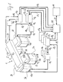
- the in Fig. 1 The sprue system and control part of a die casting machine shown with the components of interest includes a hot runner gate system 1 of modular construction comprising a manifold block assembly 2 and sprue block units attached thereto on a sprue side, in the example shown four sprue block units 3a, 3b, 3c, 3d.
- the die casting machine can be, for example, a hot-chamber die casting machine for zinc or magnesium die-casting, alternatively also a hot-chamber die casting machine for other materials castable therewith or a die casting machine for metal diecasting of the cold chamber type.
- the distributor block assembly 2 includes a longitudinal distributor block 2a and two transverse distributor blocks 2b arranged at opposite end regions of the longitudinal distributor block 2a.
- the longitudinal distribution block 2a has an in Fig. 1 upper side a central inlet opening 4 as Angus mouthpiece of the hot runner-Angusssystems 1, to which in a conventional, not further shown manner, an end nozzle of a casting piston unit of an upstream melt metering unit of the die casting machine can be attached. From Angus mouthpiece 4 performs a longitudinal center rotor channel 5, as in the sectional view of Fig.
- Each sprue block unit 3a to 3d is constructed in the same way from a block body 8 with integrated heating.
- the construction of the respective sprue block units 3a to 3d is shown in the sectional views of FIGS FIGS. 2 and 3 to recognize closer. Specifically, it includes in the example shown, a T-shaped base body 9 with elongated central dome 9a, in which the supply channel 7 is introduced as a central axial bore, and thereof quer querendem foot part 9b.
- foot part 9b In the foot part 9b are formed from the mouth of the inlet channel 7 to two opposite sides transverse laxative runners 11a, 11b, which open in the corresponding lower side region of the sprue block unit 3a to 3d, each with a slot-shaped gate opening 12a, 12b close to the gate.
- a thermal insulation layer 10 is provided in the foot part 9b.
- this melt-carrying channel system of the sprue block unit 3a to 3d is actively heated in a targeted manner.
- the integrated heater comprises a first heating device serving primarily the inlet channel heating and a second heating device serving primarily for sprue channel heating, which can be controlled or regulated separately from the first heating device.
- the first heating device includes two separately controllable heating circuits 13a, 13b, which are arranged on the lateral surface of the central dome 9a
- the second heating device has two separately controllable electrical heating circuits 14a, 14b, which are also separated from each other and separate from the heating circuits 13a , 13b of the first heating device are controllable and are arranged on the base part 9b of the base body 9.
- the electric heating circuits 13a to 14b e.g. can be realized by suitably configured Schudrahtiata, shielded by a thermal insulation ring 15, which in turn is surrounded by an outside flush with the foot part 9b arranged outer shell 16 of the sprue block unit 3a to 3d.
- each runner block unit 3a to 3d is as in FIG Fig. 2 represented, in each case a heating control loop associated with a control unit 17, which emits via an electrical amplifier 18 suitable control signals 19, ie heating current signals, separately for each of the separately controllable heating circuits or heating elements 13a to 14b.
- suitable control signals 19 ie heating current signals
- corresponding temperature actual value information 20 with respect to each heating circuit 13a to 14b of the control unit 17 is supplied, which in consideration of taking over a Setpoint input input setpoint information 21, the control signals 19 generates.
- the second heater for the sprue heating in addition to the first heater for Zulaufkanalbeloomung can be with this heating loop by means of suitable specification of the corresponding temperature setpoint information a desired temperature profile for the heated, consisting of the inlet channel 7 and the sprue channels 11 a, 11 b melt-carrying channel the sprue block unit 3a to 3d choose very variable and comply very precisely.
- the respective heating device is made up of a plurality of independently controllable heating circuits or heating elements
- the temperature profile in the inlet channel region and / or in the sprue channel region can also be adjusted and regulated comparatively fine.
- a temperature profile which varies depending on the location along the melt path or conveying path of the melt in the inlet channel 7 and / or the sprue channels 11a, 11b can also be predetermined and regulated.
- the melt can also be actively heated in the manifold block assembly 2 before reaching the sprue block units 3a to 3d.
- corresponding further heating devices are used in the longitudinal distribution block 2a integrated heating elements, eg in Fig. 3 shown heating wires 23, and integrated in the transverse distribution blocks 2b heating elements, eg in Fig. 2 shown heating wires 22.
- Fig. 1 how out Fig. 1 can be seen, is the in Fig. 2 for one of the sprue block units 3a heating control loop part of an overall heating control loop for all actively heated components of the hot runner Angusssystems 1 with a higher-level central control unit ZR, individual control units 17 1 to 17 4 and associated control signal amplifiers or power units 18 1 to 18 4 for each of Angle block units 3 a to 3d, a single control unit 17 5 with associated power section 18 5 for the controlled heating of the longitudinal manifold block 2a and two individual control units 17 6 , 17 7 each with associated power section 18 6 , 18 7 for the separate heating of each of the two transverse manifolds 2b.
- Each of the individual control units 17 1 to 17 7 corresponds in their operation of the control unit 17 of Fig. 2 and receives from each of its associated and in the sprue block unit 3a to 3d or in the transverse manifold blocks 2b and the longitudinal manifold block 2a suitably arranged temperature sensor corresponding temperature actual value information 20 i .
- each individual control unit 17 i outputs an associated status signal 23 i to the central control unit ZR, which contains information about the temperature in the associated sprue system area, which is heated by the heating element or heating circuit that is controlled by this control unit becomes.
- this status signal 23 i comprises information about Whether the temperature regulated by the respective individual control loop is within a setpoint temperature window or setpoint temperature range specified by the setpoint information 21 i or not.
- the central control unit ZR separately for each of the sprue block units 3a to 3d, the two transverse manifolds 2b and the longitudinal manifold block 2a individual set temperatures or setpoint temperature ranges to be maintained as temperature profiles are set, which are then adjusted by the individually associated individual control loops .
- the central control unit ZR depending on the system design and application, in addition to the mentioned heating control for the hot runner runner system fulfill further control tasks. In the example shown, it stands with a central machine control MS of the die casting machine in bidirectional communication connection 24.
- this is used, inter alia, to inform the central machine controller MS as to whether the heating temperature profiles or setpoint temperature ranges individually individually predetermined for the various heatable components of the hot runner gate system 1 have been achieved or maintained.
- the central machine controller MS uses this information to release or start a respective mold filling operation and thus the feeding of melt into the hot runner-gate system 1 only when it has been informed by the central control unit ZR that all predetermined temperature profiles or Set temperatures for the individual heatable components of the hot runner-Angusssystems 1, ie for the sprue block units 3a to 3d, the transverse manifold blocks 2b and the longitudinal manifold block 2a, achieved or respected.
- the temperature in one or more components of the hot runner gate system 1, eg the temperature in the longitudinal manifold block 2a or one of the two transverse distributor blocks 2b or the temperature for the inlet channel 7 and / or the temperature for at least one of the two sprue channels 11a, 11b in one of the sprue block units 3a to 3d does not lie in the desired, predetermined nominal temperature window.
- a further advantage of the invention is the modular design of the hot runner gate system 1, which can be realized in virtually any desired configuration from one or more runner block units, which are designed as units which can be used independently in a respective casting mold, and an upstream manifold block structure.
- runner block units which are designed as units which can be used independently in a respective casting mold, and an upstream manifold block structure.
- a suitable number of sprue block units for example with the in FIGS. 2 and 3 shown construction over a solid mold half distributed in corresponding recesses thereof are used.
- Fig. 1 By way of example, a configuration with four sprue block units in a rectangular distribution is shown.
- the mating manifold construction with a longitudinal manifold block and two transverse manifold blocks distributes the melt to the runner block units and also serves as a common support or mounting frame to which the sprue block assemblies are attached.
- any other number of such stand-alone sprue block units may be used in any other geometric arrangement, with appropriate associated manifold structure, which in turn may consist of a single manifold block or a plurality of manifold blocks attached to one another depending on the application.
- Fig. 4 shows the gating system 1 in an installed position in a mold with a fixed mold half 25 and a movable mold half 27 which abut each other in closed mold, as shown, along a parting plane 26 to form a mold cavity 28, the sectional plane of Fig. 4 those of Fig. 2 corresponds, ie it can be recognized in Fig. 4 the sprue block unit 3a with its associated transverse distributor 2 B.
- the sprue system 1 with its four sprue block units and its distributor block structure is inserted into corresponding recesses 29 of the fixed mold half 25.
- the gate openings 12a, 12b are opposite a gate channel 30, which leads with a short length directly into the mold cavity 28, from which in the sectional plane of the Fig. 4 only a small section can be seen.
- the supplied melt passes from the rotor channel 6 of the transverse distributor block 2b into the inlet channel 7 of the respective sprue block unit, then distributes itself into the sprue channels 11a, 11b and is forced into the mold cavity 28 via the gate openings 12a, 12b and the gate channels 30. In this case, it is actively heated on its conveying path until it leaves the sprue openings 12a, 12b.
- the heating in the respective sprue block unit by the two separately controllable or controllable heaters with one or more heating circuits 13a, 13b and 14a, 14b for heating the inlet channel 7 and the sprue channels 11a, 11b very flexible and sensitively, in particular a desired temperature profile for the conveying path of the melt in the respective sprue block unit can be predetermined and maintained.
- the melt can be up to its entry into the mold cavity 28 via the gates 30 in a predeterminable manner controlled or controlled active heating.
- a hot runner runner system having a whole set of different configurations of runner block units, each with associated manifold block construction, may be provided for use in various molds.
- the respective sprue block unit is designed as an independent unit which can be used in a respective casting mold and consequently is not an insoluble component of a fixed mold half or of a sprue block mounted inseparably thereon, the respective sprue block unit or an entire hot runner gate system with one or more sprue block units and associated manifold block construction are used for different molds when needed, ie the sprue block unit or the hot runner gate system, after it was first used in a first mold, removed therefrom and can subsequently or later in another mold can be used.
- FIG. 5 a configuration of a hot runner-Angusssystems 1 'according to the invention, the three sprue block units 3e, 3f, 3g of the in FIGS. 2 and 3 shown in a star-shaped, triangular arrangement with a manifold block construction, which is formed by a single, three-pronged manifold block 2 'with inlet-side, central Angusmund Kab 4'.
- a manifold block construction which is formed by a single, three-pronged manifold block 2 'with inlet-side, central Angusmund Fabric 4'.
- a manifold block construction which is formed by a single, three-pronged manifold block 2 'with inlet-side, central Angusmund Kab 4'.
- the distributor block 2 'and the sprue block units 3e, 3f, 3g are in the same manner as above for the embodiment of Fig. 1 to 4 described separately associated heating elements associated with individual heating control circuits and an associated central control unit, which here no repeated description needs. Otherwise, the hot runner gate system corresponds to 1 'of Fig. 5 in its mode of action and its advantages to that of the Fig. 1 to 4 , to which reference can be made.
- the modular hot runner gate system according to the invention is suitable e.g. for hot chamber die casting machines, but it is equally usable for die casting machines of the cold chamber type.
Landscapes
- Engineering & Computer Science (AREA)
- Mechanical Engineering (AREA)
- Moulds For Moulding Plastics Or The Like (AREA)
- Molds, Cores, And Manufacturing Methods Thereof (AREA)
- Encapsulation Of And Coatings For Semiconductor Or Solid State Devices (AREA)
- Injection Moulding Of Plastics Or The Like (AREA)
Priority Applications (2)
| Application Number | Priority Date | Filing Date | Title |
|---|---|---|---|
| EP10194415.5A EP2295172B1 (de) | 2007-05-24 | 2007-05-24 | Angussblockeinheit, Angusssystem und Steuerungseinrichtung für eine Druckgiessmaschine |
| PL10194415T PL2295172T3 (pl) | 2007-05-24 | 2007-05-24 | Jednostka bloku wlewowego, układ wlewowy i urządzenie sterujące dla maszyny do odlewania ciśnieniowego |
Applications Claiming Priority (2)
| Application Number | Priority Date | Filing Date | Title |
|---|---|---|---|
| EP10194415.5A EP2295172B1 (de) | 2007-05-24 | 2007-05-24 | Angussblockeinheit, Angusssystem und Steuerungseinrichtung für eine Druckgiessmaschine |
| EP07010321A EP1997571B1 (de) | 2007-05-24 | 2007-05-24 | Angussblockeinheit, Angusssystem und Steuerungseinrichtung für eine Druckgießmaschine |
Related Parent Applications (2)
| Application Number | Title | Priority Date | Filing Date |
|---|---|---|---|
| EP07010321.3 Division | 2007-05-24 | ||
| EP07010321A Division EP1997571B1 (de) | 2007-05-24 | 2007-05-24 | Angussblockeinheit, Angusssystem und Steuerungseinrichtung für eine Druckgießmaschine |
Publications (2)
| Publication Number | Publication Date |
|---|---|
| EP2295172A1 EP2295172A1 (de) | 2011-03-16 |
| EP2295172B1 true EP2295172B1 (de) | 2014-12-31 |
Family
ID=38267505
Family Applications (2)
| Application Number | Title | Priority Date | Filing Date |
|---|---|---|---|
| EP10194415.5A Active EP2295172B1 (de) | 2007-05-24 | 2007-05-24 | Angussblockeinheit, Angusssystem und Steuerungseinrichtung für eine Druckgiessmaschine |
| EP07010321A Active EP1997571B1 (de) | 2007-05-24 | 2007-05-24 | Angussblockeinheit, Angusssystem und Steuerungseinrichtung für eine Druckgießmaschine |
Family Applications After (1)
| Application Number | Title | Priority Date | Filing Date |
|---|---|---|---|
| EP07010321A Active EP1997571B1 (de) | 2007-05-24 | 2007-05-24 | Angussblockeinheit, Angusssystem und Steuerungseinrichtung für eine Druckgießmaschine |
Country Status (7)
| Country | Link |
|---|---|
| US (2) | US8104529B2 (pl) |
| EP (2) | EP2295172B1 (pl) |
| JP (1) | JP5657857B2 (pl) |
| CN (1) | CN101310894B (pl) |
| AT (1) | ATE494088T1 (pl) |
| DE (1) | DE502007006186D1 (pl) |
| PL (2) | PL1997571T3 (pl) |
Cited By (1)
| Publication number | Priority date | Publication date | Assignee | Title |
|---|---|---|---|---|
| US10618108B2 (en) | 2015-06-05 | 2020-04-14 | Oskar Frech Gmbh + Co. Kg | Hot runner feed system for a diecasting mould |
Families Citing this family (12)
| Publication number | Priority date | Publication date | Assignee | Title |
|---|---|---|---|---|
| EP2295172B1 (de) * | 2007-05-24 | 2014-12-31 | Oskar Frech GmbH + Co. KG | Angussblockeinheit, Angusssystem und Steuerungseinrichtung für eine Druckgiessmaschine |
| DE102012112370A1 (de) * | 2012-12-17 | 2014-06-18 | Krones Ag | Vorrichtung zum Erwärmen von Kunststoffvorformlingen |
| DE102015100861B4 (de) * | 2015-01-21 | 2018-07-19 | TransMIT Gesellschaft für Technologietransfer mbH | Heißkanal für eine Druckgussvorrichtung und Betriebsverfahren dafür |
| DE102015210403A1 (de) | 2015-06-05 | 2016-12-08 | Oskar Frech Gmbh + Co. Kg | Angusssystem für eine Druckgießform |
| DE102015224414A1 (de) * | 2015-12-07 | 2017-06-08 | Volkswagen Aktiengesellschaft | Gusseinrichtung |
| CN106216635A (zh) * | 2016-08-09 | 2016-12-14 | 上海普锐赛司实业有限公司 | 一种压铸材料温度控制设备及温度控制方法 |
| CN106735075B (zh) * | 2016-12-30 | 2019-01-15 | 宁波海天金属成型设备有限公司 | 一种压铸机智能开合模控制方法及控制系统 |
| CN108568497A (zh) * | 2017-03-09 | 2018-09-25 | 四川省宜宾普什驱动有限责任公司 | 一种高速铁路钢轨扣件专用热流道装置 |
| CN110076316A (zh) * | 2019-05-26 | 2019-08-02 | 深圳市宝田精工塑胶模具有限公司 | 一种锌合金产品的成型方法及锌合金成型模具 |
| CN113600788B (zh) * | 2021-07-14 | 2022-12-27 | 江西省铭鑫荣智能科技有限公司 | 一种制作精密结构件的压铸机械脱模分离设备及实施方法 |
| CN114309535B (zh) * | 2021-12-30 | 2024-01-02 | 宁波三诚压铸模具有限公司 | 直流电感盒成型模具 |
| CN117026060A (zh) * | 2023-07-17 | 2023-11-10 | 江苏圣珀新材料科技有限公司 | 一种适合oled柔性屏金属掩膜板背板箔材用的4j36熔炼方法 |
Citations (1)
| Publication number | Priority date | Publication date | Assignee | Title |
|---|---|---|---|---|
| JP2005271014A (ja) * | 2004-03-24 | 2005-10-06 | Matsushita Electric Ind Co Ltd | ホットランナを用いた多数個取り金属射出成形金型 |
Family Cites Families (20)
| Publication number | Priority date | Publication date | Assignee | Title |
|---|---|---|---|---|
| JPS63137561A (ja) | 1986-11-28 | 1988-06-09 | Fuso Light Alloys Co Ltd | ホツトチヤンバダイカストマシン |
| DE69302469T2 (de) * | 1992-03-06 | 1996-11-28 | Teetotum Ltd | Kunststoffspritzgiessmaschine mit Leckdetektor und System dafür |
| CA2073710C (en) * | 1992-07-13 | 2000-03-28 | Jobst Ulrich Gellert | Injection molding nozzle with removable forward member |
| JP3016722B2 (ja) * | 1995-12-06 | 2000-03-06 | 株式会社日本製鋼所 | 金型を用いた金属射出成形方法及び金属射出成形用金型 |
| CA2233433C (en) * | 1998-03-27 | 2007-07-31 | Mold-Masters Limited | Injection molding cylindrical manifold insert and method |
| JP2000006221A (ja) * | 1998-06-29 | 2000-01-11 | Sekisui Chem Co Ltd | 射出成形装置 |
| JP2001047212A (ja) * | 1999-08-03 | 2001-02-20 | Juo:Kk | 射出成形装置 |
| US6405785B1 (en) * | 2000-01-28 | 2002-06-18 | Mold-Masters Limited | Injection molding component with heating element and method of making |
| JP2001212660A (ja) * | 2000-01-31 | 2001-08-07 | Matsushita Electric Ind Co Ltd | 金属成形金型装置 |
| JP3590315B2 (ja) * | 2000-02-03 | 2004-11-17 | 株式会社日本製鋼所 | 成形機用金型の温度制御方法および成形機用金型装置 |
| JP2002103022A (ja) * | 2000-09-29 | 2002-04-09 | Ahresty Corp | 鋳造用給湯装置 |
| DE50012864D1 (de) * | 2000-10-31 | 2006-07-06 | Frech Oskar Gmbh & Co | Einrichtung zur Herstellung von Metall-Druckgussteilen, insbesondere aus NE-Metallen |
| JP2002160041A (ja) * | 2000-11-24 | 2002-06-04 | Sanyo Electric Co Ltd | 金属薄肉成形体用金型およびそれを用いた金属薄肉成形体の製法 |
| AU2930502A (en) | 2001-08-23 | 2003-02-27 | Commonwealth Scientific And Industrial Research Organisation | Improved magnesium alloy castings |
| JP2004050199A (ja) * | 2002-07-17 | 2004-02-19 | Matsushita Electric Ind Co Ltd | 金属成形金型装置 |
| JP2004090063A (ja) * | 2002-09-02 | 2004-03-25 | Honda Motor Co Ltd | 鋳造用金型 |
| JP2004174991A (ja) * | 2002-11-28 | 2004-06-24 | Matsushita Electric Ind Co Ltd | 光ディスク2個取り成形用ホットランナー金型 |
| CA2453170C (en) * | 2002-12-20 | 2012-02-21 | Mold-Masters Limited | Lateral gating injection molding apparatus |
| US7810549B2 (en) * | 2007-01-05 | 2010-10-12 | Ford Global Technologies, Llc | Adaptive and universal hot runner manifold for die casting |
| EP2295172B1 (de) * | 2007-05-24 | 2014-12-31 | Oskar Frech GmbH + Co. KG | Angussblockeinheit, Angusssystem und Steuerungseinrichtung für eine Druckgiessmaschine |
-
2007
- 2007-05-24 EP EP10194415.5A patent/EP2295172B1/de active Active
- 2007-05-24 DE DE502007006186T patent/DE502007006186D1/de active Active
- 2007-05-24 PL PL07010321T patent/PL1997571T3/pl unknown
- 2007-05-24 AT AT07010321T patent/ATE494088T1/de active
- 2007-05-24 EP EP07010321A patent/EP1997571B1/de active Active
- 2007-05-24 PL PL10194415T patent/PL2295172T3/pl unknown
-
2008
- 2008-05-23 US US12/126,597 patent/US8104529B2/en active Active
- 2008-05-23 JP JP2008135857A patent/JP5657857B2/ja active Active
- 2008-05-23 CN CN200810109108.9A patent/CN101310894B/zh active Active
-
2011
- 2011-12-16 US US13/328,210 patent/US8302660B2/en active Active
Patent Citations (1)
| Publication number | Priority date | Publication date | Assignee | Title |
|---|---|---|---|---|
| JP2005271014A (ja) * | 2004-03-24 | 2005-10-06 | Matsushita Electric Ind Co Ltd | ホットランナを用いた多数個取り金属射出成形金型 |
Cited By (1)
| Publication number | Priority date | Publication date | Assignee | Title |
|---|---|---|---|---|
| US10618108B2 (en) | 2015-06-05 | 2020-04-14 | Oskar Frech Gmbh + Co. Kg | Hot runner feed system for a diecasting mould |
Also Published As
| Publication number | Publication date |
|---|---|
| JP5657857B2 (ja) | 2015-01-21 |
| PL2295172T3 (pl) | 2015-07-31 |
| US8104529B2 (en) | 2012-01-31 |
| EP2295172A1 (de) | 2011-03-16 |
| ATE494088T1 (de) | 2011-01-15 |
| CN101310894B (zh) | 2014-01-29 |
| HK1123253A1 (en) | 2009-06-12 |
| CN101310894A (zh) | 2008-11-26 |
| US20120145352A1 (en) | 2012-06-14 |
| DE502007006186D1 (de) | 2011-02-17 |
| PL1997571T3 (pl) | 2011-05-31 |
| US8302660B2 (en) | 2012-11-06 |
| HK1151259A1 (en) | 2012-01-27 |
| EP1997571A1 (de) | 2008-12-03 |
| JP2008290153A (ja) | 2008-12-04 |
| US20080289791A1 (en) | 2008-11-27 |
| EP1997571B1 (de) | 2011-01-05 |
Similar Documents
| Publication | Publication Date | Title |
|---|---|---|
| EP2295172B1 (de) | Angussblockeinheit, Angusssystem und Steuerungseinrichtung für eine Druckgiessmaschine | |
| EP1201335B1 (de) | Einrichtung zur Herstellung von Metall-Druckgussteilen, insbesondere aus NE-Metallen | |
| EP3302851B1 (de) | Angusssystem für eine druckgiessform | |
| DE69603146T2 (de) | Spritzgiesstorpedo aus Karbid | |
| DE4137664B4 (de) | Spritzgießvorrichtung mit gesondertem Heizelement im den Formhohlraum bildenden Einsatz | |
| EP2808104B1 (de) | Gießventil mit einem Nachverdichtungskolben | |
| DE4137720C2 (de) | Spritzgießdüse mit konischem Heizelement in der Nähe der Angussöffnung | |
| EP3191287B1 (de) | Verfahren und spritzgussdüse zum herstellen von spritzgussteilen aus kunststoff | |
| DE69603538T2 (de) | Spritzgiessvorrichtung mit seitlichem Anschnitt mit radial montierten Anschnitteinsätzen | |
| DE60029444T2 (de) | Spritzgiess-heizelement mit integriertem schmelze-kanal | |
| DE60313132T2 (de) | Anschnittsystem für reduzierung von spritzmasseaustritt aus dem angusskanal | |
| DE60309107T2 (de) | Nadelverschlussdüse für Schmelzeübergabevorrichtung in einem Heisskanal | |
| EP2205419A1 (de) | Angussadapter sowie angusssystem für einen angussadapter | |
| DE4200982A1 (de) | Spritzgussvorrichtung mit eingebauter kuehlung in einem vorderbereich der duese | |
| DE19943797B4 (de) | Kunststoffeinspritzvorrichtung für Spritzgussmaschinen mit einem Ventilsystem, das Einzelkolben-betätigte Mehrfach-Ventilstifte aufweist | |
| DE4442667C2 (de) | Spritzgussvorrichtung mit senkrechten beheizten Angüssen | |
| EP3423215B1 (de) | Druckgussdüsensystem | |
| DE3538206A1 (de) | Warmspritzduese zur verwendung mit einer pressform zum eingusslosen spritzen von kunststoffmaterial | |
| DE112014005406B4 (de) | Spritzgießvorrichtung und Verfahren zum Spritzgießen mit einer Spritzgießvorrichtung | |
| EP3041655B1 (de) | Kaltkanal-schmelzeverteiler | |
| EP3822059B1 (de) | Anordnung zum einspritzen von kunststoff in eine langgestreckte spritzgussform einer kunststoffspritzmaschine | |
| AT520389B1 (de) | Verfahren zum Herstellen von Spritzgussteilen aus Kunststoff | |
| WO2017198340A1 (de) | Heisskanalsystem und damit verbundene düsenspitzenheizeinrichtungen | |
| WO2015032489A1 (de) | Kaltkanal-schmelzeverteiler | |
| DE102014111032B3 (de) | Gießventil und Gießvorrichtung |
Legal Events
| Date | Code | Title | Description |
|---|---|---|---|
| PUAI | Public reference made under article 153(3) epc to a published international application that has entered the european phase |
Free format text: ORIGINAL CODE: 0009012 |
|
| AC | Divisional application: reference to earlier application |
Ref document number: 1997571 Country of ref document: EP Kind code of ref document: P |
|
| AK | Designated contracting states |
Kind code of ref document: A1 Designated state(s): AT BE BG CH CY CZ DE DK EE ES FI FR GB GR HU IE IS IT LI LT LU LV MC MT NL PL PT RO SE SI SK TR |
|
| 17P | Request for examination filed |
Effective date: 20110616 |
|
| 17Q | First examination report despatched |
Effective date: 20110725 |
|
| REG | Reference to a national code |
Ref country code: HK Ref legal event code: DE Ref document number: 1151259 Country of ref document: HK |
|
| GRAP | Despatch of communication of intention to grant a patent |
Free format text: ORIGINAL CODE: EPIDOSNIGR1 |
|
| INTG | Intention to grant announced |
Effective date: 20140922 |
|
| GRAS | Grant fee paid |
Free format text: ORIGINAL CODE: EPIDOSNIGR3 |
|
| GRAA | (expected) grant |
Free format text: ORIGINAL CODE: 0009210 |
|
| AC | Divisional application: reference to earlier application |
Ref document number: 1997571 Country of ref document: EP Kind code of ref document: P |
|
| AK | Designated contracting states |
Kind code of ref document: B1 Designated state(s): AT BE BG CH CY CZ DE DK EE ES FI FR GB GR HU IE IS IT LI LT LU LV MC MT NL PL PT RO SE SI SK TR |
|
| REG | Reference to a national code |
Ref country code: CH Ref legal event code: EP Ref country code: GB Ref legal event code: FG4D Free format text: NOT ENGLISH |
|
| REG | Reference to a national code |
Ref country code: IE Ref legal event code: FG4D Free format text: LANGUAGE OF EP DOCUMENT: GERMAN |
|
| REG | Reference to a national code |
Ref country code: CH Ref legal event code: NV Representative=s name: DR. LUSUARDI AG, CH |
|
| REG | Reference to a national code |
Ref country code: AT Ref legal event code: REF Ref document number: 704070 Country of ref document: AT Kind code of ref document: T Effective date: 20150215 |
|
| REG | Reference to a national code |
Ref country code: DE Ref legal event code: R096 Ref document number: 502007013663 Country of ref document: DE Effective date: 20150219 |
|
| REG | Reference to a national code |
Ref country code: ES Ref legal event code: FG2A Ref document number: 2531012 Country of ref document: ES Kind code of ref document: T3 Effective date: 20150310 |
|
| REG | Reference to a national code |
Ref country code: SE Ref legal event code: TRGR |
|
| PG25 | Lapsed in a contracting state [announced via postgrant information from national office to epo] |
Ref country code: FI Free format text: LAPSE BECAUSE OF FAILURE TO SUBMIT A TRANSLATION OF THE DESCRIPTION OR TO PAY THE FEE WITHIN THE PRESCRIBED TIME-LIMIT Effective date: 20141231 Ref country code: LT Free format text: LAPSE BECAUSE OF FAILURE TO SUBMIT A TRANSLATION OF THE DESCRIPTION OR TO PAY THE FEE WITHIN THE PRESCRIBED TIME-LIMIT Effective date: 20141231 |
|
| REG | Reference to a national code |
Ref country code: NL Ref legal event code: VDEP Effective date: 20141231 |
|
| REG | Reference to a national code |
Ref country code: LT Ref legal event code: MG4D |
|
| PG25 | Lapsed in a contracting state [announced via postgrant information from national office to epo] |
Ref country code: LV Free format text: LAPSE BECAUSE OF FAILURE TO SUBMIT A TRANSLATION OF THE DESCRIPTION OR TO PAY THE FEE WITHIN THE PRESCRIBED TIME-LIMIT Effective date: 20141231 Ref country code: GR Free format text: LAPSE BECAUSE OF FAILURE TO SUBMIT A TRANSLATION OF THE DESCRIPTION OR TO PAY THE FEE WITHIN THE PRESCRIBED TIME-LIMIT Effective date: 20150401 |
|
| PG25 | Lapsed in a contracting state [announced via postgrant information from national office to epo] |
Ref country code: NL Free format text: LAPSE BECAUSE OF FAILURE TO SUBMIT A TRANSLATION OF THE DESCRIPTION OR TO PAY THE FEE WITHIN THE PRESCRIBED TIME-LIMIT Effective date: 20141231 |
|
| REG | Reference to a national code |
Ref country code: SK Ref legal event code: T3 Ref document number: E 18372 Country of ref document: SK |
|
| PG25 | Lapsed in a contracting state [announced via postgrant information from national office to epo] |
Ref country code: RO Free format text: LAPSE BECAUSE OF FAILURE TO SUBMIT A TRANSLATION OF THE DESCRIPTION OR TO PAY THE FEE WITHIN THE PRESCRIBED TIME-LIMIT Effective date: 20141231 |
|
| REG | Reference to a national code |
Ref country code: HK Ref legal event code: GR Ref document number: 1151259 Country of ref document: HK Ref country code: PL Ref legal event code: T3 |
|
| PG25 | Lapsed in a contracting state [announced via postgrant information from national office to epo] |
Ref country code: IS Free format text: LAPSE BECAUSE OF FAILURE TO SUBMIT A TRANSLATION OF THE DESCRIPTION OR TO PAY THE FEE WITHIN THE PRESCRIBED TIME-LIMIT Effective date: 20150430 |
|
| REG | Reference to a national code |
Ref country code: DE Ref legal event code: R097 Ref document number: 502007013663 Country of ref document: DE |
|
| PG25 | Lapsed in a contracting state [announced via postgrant information from national office to epo] |
Ref country code: EE Free format text: LAPSE BECAUSE OF FAILURE TO SUBMIT A TRANSLATION OF THE DESCRIPTION OR TO PAY THE FEE WITHIN THE PRESCRIBED TIME-LIMIT Effective date: 20141231 Ref country code: DK Free format text: LAPSE BECAUSE OF FAILURE TO SUBMIT A TRANSLATION OF THE DESCRIPTION OR TO PAY THE FEE WITHIN THE PRESCRIBED TIME-LIMIT Effective date: 20141231 |
|
| PLBE | No opposition filed within time limit |
Free format text: ORIGINAL CODE: 0009261 |
|
| STAA | Information on the status of an ep patent application or granted ep patent |
Free format text: STATUS: NO OPPOSITION FILED WITHIN TIME LIMIT |
|
| 26N | No opposition filed |
Effective date: 20151001 |
|
| PG25 | Lapsed in a contracting state [announced via postgrant information from national office to epo] |
Ref country code: MC Free format text: LAPSE BECAUSE OF FAILURE TO SUBMIT A TRANSLATION OF THE DESCRIPTION OR TO PAY THE FEE WITHIN THE PRESCRIBED TIME-LIMIT Effective date: 20141231 Ref country code: LU Free format text: LAPSE BECAUSE OF FAILURE TO SUBMIT A TRANSLATION OF THE DESCRIPTION OR TO PAY THE FEE WITHIN THE PRESCRIBED TIME-LIMIT Effective date: 20150524 |
|
| REG | Reference to a national code |
Ref country code: IE Ref legal event code: MM4A |
|
| PG25 | Lapsed in a contracting state [announced via postgrant information from national office to epo] |
Ref country code: SI Free format text: LAPSE BECAUSE OF FAILURE TO SUBMIT A TRANSLATION OF THE DESCRIPTION OR TO PAY THE FEE WITHIN THE PRESCRIBED TIME-LIMIT Effective date: 20141231 |
|
| PG25 | Lapsed in a contracting state [announced via postgrant information from national office to epo] |
Ref country code: IE Free format text: LAPSE BECAUSE OF NON-PAYMENT OF DUE FEES Effective date: 20150524 |
|
| REG | Reference to a national code |
Ref country code: FR Ref legal event code: PLFP Year of fee payment: 10 |
|
| PG25 | Lapsed in a contracting state [announced via postgrant information from national office to epo] |
Ref country code: MT Free format text: LAPSE BECAUSE OF FAILURE TO SUBMIT A TRANSLATION OF THE DESCRIPTION OR TO PAY THE FEE WITHIN THE PRESCRIBED TIME-LIMIT Effective date: 20141231 |
|
| REG | Reference to a national code |
Ref country code: FR Ref legal event code: PLFP Year of fee payment: 11 |
|
| PG25 | Lapsed in a contracting state [announced via postgrant information from national office to epo] |
Ref country code: HU Free format text: LAPSE BECAUSE OF FAILURE TO SUBMIT A TRANSLATION OF THE DESCRIPTION OR TO PAY THE FEE WITHIN THE PRESCRIBED TIME-LIMIT; INVALID AB INITIO Effective date: 20070524 Ref country code: BG Free format text: LAPSE BECAUSE OF FAILURE TO SUBMIT A TRANSLATION OF THE DESCRIPTION OR TO PAY THE FEE WITHIN THE PRESCRIBED TIME-LIMIT Effective date: 20141231 |
|
| PG25 | Lapsed in a contracting state [announced via postgrant information from national office to epo] |
Ref country code: CY Free format text: LAPSE BECAUSE OF FAILURE TO SUBMIT A TRANSLATION OF THE DESCRIPTION OR TO PAY THE FEE WITHIN THE PRESCRIBED TIME-LIMIT Effective date: 20141231 |
|
| PG25 | Lapsed in a contracting state [announced via postgrant information from national office to epo] |
Ref country code: BE Free format text: LAPSE BECAUSE OF NON-PAYMENT OF DUE FEES Effective date: 20150531 |
|
| REG | Reference to a national code |
Ref country code: FR Ref legal event code: PLFP Year of fee payment: 12 |
|
| PG25 | Lapsed in a contracting state [announced via postgrant information from national office to epo] |
Ref country code: PT Free format text: LAPSE BECAUSE OF FAILURE TO SUBMIT A TRANSLATION OF THE DESCRIPTION OR TO PAY THE FEE WITHIN THE PRESCRIBED TIME-LIMIT Effective date: 20141231 |
|
| PGFP | Annual fee paid to national office [announced via postgrant information from national office to epo] |
Ref country code: GB Payment date: 20240522 Year of fee payment: 18 |
|
| PGFP | Annual fee paid to national office [announced via postgrant information from national office to epo] |
Ref country code: DE Payment date: 20240522 Year of fee payment: 18 |
|
| PGFP | Annual fee paid to national office [announced via postgrant information from national office to epo] |
Ref country code: CH Payment date: 20240602 Year of fee payment: 18 |
|
| PGFP | Annual fee paid to national office [announced via postgrant information from national office to epo] |
Ref country code: ES Payment date: 20240614 Year of fee payment: 18 |
|
| PGFP | Annual fee paid to national office [announced via postgrant information from national office to epo] |
Ref country code: CZ Payment date: 20240510 Year of fee payment: 18 Ref country code: AT Payment date: 20240517 Year of fee payment: 18 |
|
| PGFP | Annual fee paid to national office [announced via postgrant information from national office to epo] |
Ref country code: SK Payment date: 20240517 Year of fee payment: 18 |
|
| PGFP | Annual fee paid to national office [announced via postgrant information from national office to epo] |
Ref country code: FR Payment date: 20240516 Year of fee payment: 18 |
|
| PGFP | Annual fee paid to national office [announced via postgrant information from national office to epo] |
Ref country code: PL Payment date: 20240423 Year of fee payment: 18 |
|
| PGFP | Annual fee paid to national office [announced via postgrant information from national office to epo] |
Ref country code: TR Payment date: 20240513 Year of fee payment: 18 Ref country code: SE Payment date: 20240522 Year of fee payment: 18 |
|
| PGFP | Annual fee paid to national office [announced via postgrant information from national office to epo] |
Ref country code: IT Payment date: 20240531 Year of fee payment: 18 |
|
| REG | Reference to a national code |
Ref country code: DE Ref legal event code: R119 Ref document number: 502007013663 Country of ref document: DE |
|
| REG | Reference to a national code |
Ref country code: CH Ref legal event code: H13 Free format text: ST27 STATUS EVENT CODE: U-0-0-H10-H13 (AS PROVIDED BY THE NATIONAL OFFICE) Effective date: 20251223 |
|
| PG25 | Lapsed in a contracting state [announced via postgrant information from national office to epo] |
Ref country code: AT Free format text: LAPSE BECAUSE OF NON-PAYMENT OF DUE FEES Effective date: 20250524 |
|
| REG | Reference to a national code |
Ref country code: SK Ref legal event code: MM4A Ref document number: E 18372 Country of ref document: SK Effective date: 20250524 |
|
| REG | Reference to a national code |
Ref country code: AT Ref legal event code: MM01 Ref document number: 704070 Country of ref document: AT Kind code of ref document: T Effective date: 20250524 |
|
| PG25 | Lapsed in a contracting state [announced via postgrant information from national office to epo] |
Ref country code: CH Free format text: LAPSE BECAUSE OF NON-PAYMENT OF DUE FEES Effective date: 20250531 |
|
| PG25 | Lapsed in a contracting state [announced via postgrant information from national office to epo] |
Ref country code: SE Free format text: LAPSE BECAUSE OF NON-PAYMENT OF DUE FEES Effective date: 20250525 Ref country code: CZ Free format text: LAPSE BECAUSE OF NON-PAYMENT OF DUE FEES Effective date: 20250524 |
|
| PG25 | Lapsed in a contracting state [announced via postgrant information from national office to epo] |
Ref country code: SK Free format text: LAPSE BECAUSE OF NON-PAYMENT OF DUE FEES Effective date: 20250524 |
|
| REG | Reference to a national code |
Ref country code: SE Ref legal event code: EUG |
|
| GBPC | Gb: european patent ceased through non-payment of renewal fee |
Effective date: 20250524 |
|
| PG25 | Lapsed in a contracting state [announced via postgrant information from national office to epo] |
Ref country code: GB Free format text: LAPSE BECAUSE OF NON-PAYMENT OF DUE FEES Effective date: 20250524 |
|
| PG25 | Lapsed in a contracting state [announced via postgrant information from national office to epo] |
Ref country code: DE Free format text: LAPSE BECAUSE OF NON-PAYMENT OF DUE FEES Effective date: 20251202 |
|
| PG25 | Lapsed in a contracting state [announced via postgrant information from national office to epo] |
Ref country code: IT Free format text: LAPSE BECAUSE OF NON-PAYMENT OF DUE FEES Effective date: 20250524 |
|
| PG25 | Lapsed in a contracting state [announced via postgrant information from national office to epo] |
Ref country code: FR Free format text: LAPSE BECAUSE OF NON-PAYMENT OF DUE FEES Effective date: 20250531 |