EP2292980B1 - Backofen mit einem mittels Rastung gesicherten Einschub - Google Patents
Backofen mit einem mittels Rastung gesicherten Einschub Download PDFInfo
- Publication number
- EP2292980B1 EP2292980B1 EP10005492.3A EP10005492A EP2292980B1 EP 2292980 B1 EP2292980 B1 EP 2292980B1 EP 10005492 A EP10005492 A EP 10005492A EP 2292980 B1 EP2292980 B1 EP 2292980B1
- Authority
- EP
- European Patent Office
- Prior art keywords
- insert
- guiding means
- latching element
- latching
- wire
- Prior art date
- Legal status (The legal status is an assumption and is not a legal conclusion. Google has not performed a legal analysis and makes no representation as to the accuracy of the status listed.)
- Active
Links
Images


Classifications
-
- F—MECHANICAL ENGINEERING; LIGHTING; HEATING; WEAPONS; BLASTING
- F24—HEATING; RANGES; VENTILATING
- F24C—DOMESTIC STOVES OR RANGES ; DETAILS OF DOMESTIC STOVES OR RANGES, OF GENERAL APPLICATION
- F24C15/00—Details
- F24C15/16—Shelves, racks or trays inside ovens; Supports therefor
Definitions
- the invention relates to an oven with a cooking space in which a slot, such as. a grid, a baking tray, a baking tray (e.g., glass), or the like may be inserted.
- a slot such as. a grid, a baking tray, a baking tray (e.g., glass), or the like may be inserted.
- the insert is held with a lateral guide and secured by means of a detent against unintentional too far pulling out.
- Each guide comprises upper and lower guide means, wherein the insert between the upper and the lower guide means is inserted, such that when pulling out of the insert tilting of the same is limited by striking the rear end of the insert to the upper guide means.
- EP 2 442 036 proposes to arrange a locking element both on the lateral guide means in the cooking chamber and on the insert
- WO 2007/077163 describes a cooking appliance with a cooking chamber and two lateral guides arranged therein, wherein a slot has a stop which limits the movement of the insert.
- the oven according to claim 1 Accordingly, a first locking element and the insert a second locking element attached to the upper slide, which snap into one another when the drawer is pulled out under tilting, but which do not engage in one another when the drawer is pulled out without tilting.
- the latching mechanism thus acts only when the drawer is pulled out under tilting, as is typically the case when the user pulls the drawer out of the oven with one hand and without manual guidance, e.g. to pour sauce over a roast.
- the latching mechanism will not act and the drawer may be easily removed from the cooking compartment.
- Fig. 1 shows an oven with a cooking chamber 1, which can be closed by a tilting door 2 front.
- guide rails 5 are arranged on opposite vertical side walls 3, 4.
- Each guide grid is a wire construction comprising two vertical wires 6 fixed to the respective side wall 3 and 4, respectively, and a plurality of horizontal wires 7, 8 which in turn are fixed to the vertical wires 6.
- Each pair of horizontal wires 7, 8 respectively form lower and upper guide means for receiving a drawer, as described below.
- the guide means are formed by the wires 7, 8. It is conceivable but also that the guide means are formed by other elements, such as by deep-drawn in the side walls of the oven moldings.
- Fig. 2 shows a section through an oven in the open state with two different slots 10, 11.
- Slot 10 has the shape of a grid, insert 11 of a baking sheet.
- Drawer 10 is shown in partially extended position and dashed in the inserted position, insert 11 only in partially extended position.
- Each insert extends between the side walls 3 and 4 of the cooking chamber and is held there laterally by a guide.
- Each guide is formed by a wire pair 7, 8.
- the respective upper wire 8 forms an upper guide means and the lower wire 7 a lower guide means.
- each insert 10, 11 lies on the lower guide means or the wire 7 and does not come into contact with the upper guide means or the wire 8.
- the drawer 10 or 11 tilts slightly forward at a certain extension position, so that the rear end 12 (ie the end facing away from the cooking chamber opening) on the upper guide means or the Wire 8 abuts, whereby the tilting of the insert is limited when pulling out.
- the two guide means or wires 7, 8 each form a stop surface or stop line for insertion. This is the part of the guide means that comes into contact with the insert.
- the stop surfaces or stop lines are largely horizontal.
- a latching mechanism which acts when the drawer 10 or 11 is pulled out in the tilted position.
- the latching mechanism is formed by a first latching element 14 and a second latching element 15.
- the first locking element 14 is on the upper guide means, that is arranged on the wire 8, the second locking element 15 on the insert 10, 11th
- the first locking element 14 is formed by an upwardly offset portion of the abutment surface of the upper guide means or wire 8, as in particular Fig. 4 is apparent. This is achieved by the wire 8 is in the region of the portion 14 upwardly bulged, that is substantially U-shaped or V-shaped upwards.
- the second latching element 15 is formed in the case of the grate 10 by a horizontal wire, in the case of the baking tray 11 of a folded, upwardly projecting portion of the baking sheet.
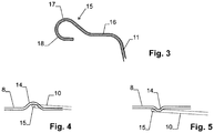
- Fig. 3 shows the configuration of the baking sheet 11 in detail. Thereafter, the edge 16 of the baking sheet on a raised portion 17, to which a downwardly bent portion 18 connects, so that an upwardly rounded locking element 15 is formed.
- the second detent element 15 enters the recess of the first detent element 14, whereby the tilt angle of the insert 10, 11 is slightly increased and further disengagement is prevented or at least made more difficult until the user raises the drawer at its outer edge and places it in a more horizontal position to release the second latching element 15 from the first latching element 14.
- the first latching element 14 As mentioned, formed by an upwardly recessed portion.
- An alternative embodiment is in Fig. 5 illustrated, according to which the first locking element 14 is formed by a downwardly projecting portion of the upper guide means.
- the latching element projects only so far down that it is indeed with a tilted slot 10, 11, but not with a horizontally guided slot 10, 11 comes into contact.
- the first (upper) locking element can not be formed by a bent section of the wire 8, but by an auxiliary element arranged on the wire 8.
- the first locking element also laterally (horizontally) protrude from the wire 8.
- the second locking element can be formed by an insert 10, 11 fixed auxiliary element.
- the two locking elements are sized and arranged so that they do not come into contact when the drawer 10, 11 in a horizontal position (ie with a vertically supported outer end of the insert) is pulled out, but if the drawer when pulling on its outer end is not supported and thus tilts when pulling down.
- first and second locking elements are provided on both sides of the insert, i. provided both in the side wall 3 and the side wall 4, so that the drawer is held on both sides.
- the second latching element is preferably arranged on an edge of the insert 10, 11, since during tilting of the insert 10, 11 during removal, the (rear) edge of the insert is lifted the furthest.
- the insert preferably has both at its rear, i. muffle matteren edge and at its front, i. outwardly directed edge in each case a second latching element.
- second locking elements are arranged on two opposite edges of the insert, the insert can be inserted into the cooking chamber 1 in two different orientations.
- the embodiment shown is the first (upper) locking element 14 respectively from the center of the upper guide means or wire 8 to the outside added.
- This has the advantage that the insert 10, 11 each engages only in a relatively far extended position.
- the guide grids for the left and right side walls 3 and 4 are each configured differently.
- the first locking element 14 is therefore arranged centrally on the upper guide means or wire 8.
Description
- Die Erfindung betrifft einen Backofen mit einem Garraum, in welchem ein Einschub, wie z.B. ein Gitter, ein Backblech, eine Backform (z.B. aus Glas) oder dergleichen eingeschoben werden kann. Der Einschub ist mit einer seitlichen Führung gehalten und mittels einer Rastung gegen unabsichtliches zu weites Herausziehen gesichert.
- Meist wird der Einschub in solchen Geräten mittels zwei seitlichen Führungen gehalten. Jede Führung umfasst dabei obere und untere Führungsmittel, wobei der Einschub zwischen das obere und das untere Führungsmittel eingeschoben wird, derart, dass beim Herausziehen des Einschubs ein Verkippen desselben durch Anschlagen des hinteren Endes des Einschubs an den oberen Führungsmitteln limitiert wird.
- Um zu verhindern, dass ein derartiger Einschub unabsichtlich zu weit aus dem Garraum herausgezogen wird, so dass er aus der Führung fällt und sich z.B. heißes Gargut gegen den Benutzer ergießt, wurde vorgeschlagen, einen Einrastmechanismus vorzusehen, indem am Einschub an geeigneter Position eine Erhöhung angeordnet wird, welche am unteren Führungsmittel beim Einschieben und Herausziehen anschlägt.
EP 2 442 036 schlägt vor, sowohl am seitlichen Führungsmittel im Garraum als auch am Einschub ein Rastelement anzuordnen - Dadurch wird die Sicherheit der Bedienung erhöht. In der Praxis wird der Einrastmechanismus jedoch oft als störend empfunden.
-
WO 2007/077163 beschreibt ein Gargerät mit einem Garraum und zwei darin angeordneten seitlichen Führungen, wobei ein Einschub einen Anschlag aufweist, der der Bewegung des Einschubs einschränkt. - Es stellt sich deshalb die Aufgabe, einen Backofen der oben beschriebenen Art bereitzustellen, welcher einfach in der Bedienung ist.
- Diese Aufgabe wird vom Backofen gemäß Anspruch 1 gelöst. Demgemäß wird am oberen Führungsmittel ein erstes Rastelement und am Einschub ein zweites Rastelement angebracht, welche ineinander einrasten, wenn der Einschub unter Verkippen herausgezogen wird, welche aber nicht ineinander einrasten, wenn der Einschub ohne Verkippen herausgezogen wird. Somit wirkt der Einrastmechanismus also nur, wenn der Einschub unter Verkippung herausgezogen wird, wie es typischerweise der Fall ist, wenn der Benutzer den Einschub nur mit einer Hand und ohne manuelle Führung aus dem Ofen herauszieht, z.B. um Sauce über einen Braten zu gießen. Wenn der Benutzer den Einschub jedoch beim Herausziehen manuell derart führt, dass er horizontal bleibt, so wirkt der Einrastmechanismus nicht, und der Einschub kann einfach aus dem Garraum entfernt werden.
- Die Erfindung ist weiter darauf eingeschränkt, dass
- das obere Führungsmittel (8) eine obere Anschlagfläche oder -linie für den Einschub (10, 11) bildet, welche im Bereich des ersten Rastelements (14) einen nach oben zurückversetzten Abschnitt aufweist, wobei das zweite Rastelement (15) beim Herausziehen des Einschubs (10, 11) unter Verkippen in den nach oben zurückversetzten Abschnitt eingreift. Dadurch wird erreicht, dass die Verkippung des Einschubs gering bleibt, außer im Bereich des Rastelements, wo sie etwas grösser ist, und/oder
- das obere Führungsmittel (8) von einem Draht gebildet wird und der Draht des oberen Führungsmittels (8) im Bereich des zurückversetzten Abschnitts nach oben ausgebuchtet ist, und/oder
- der Einschub (10, 11) ein Backblech ist und das zweite Rastelement (15) von einem gefalzten, nach oben ragenden Bereich des Backblechs gebildet ist, und/oder
- der Einschub (10, 11) ein Backblech oder eine Backform ist.
- Weitere Ausgestaltungen, Vorteile und Anwendungen der Erfindung ergeben sich aus den abhängigen Ansprüchen und aus der nun folgenden Beschreibung anhand der Figuren. Dabei zeigen:
-
Fig. 1 eine Ansicht eines Backofens mit geöffneter Tür, -
Fig. 2 einen Schnitt durch den Garraum eines Backofens mit zwei unterschiedlichen Einschüben, -
Fig. 3 einen Schnitt durch den Rand eines Backblechs, -
Fig. 4 eine erste Ausführung des ersten, d.h. oberen Rastelements und -
Fig. 5 eine zweite Ausführung des ersten Rastelements. -
Fig. 1 zeigt einen Backofen mit einem Garraum 1, der frontseitig von einer Kipptüre 2 verschlossen werden kann. Im Garraum sind an gegenüberliegenden vertikalen Seitenwänden 3, 4 Führungsgitter 5 angeordnet. Jedes Führungsgitter ist eine Drahtkonstruktion umfassend zwei vertikale Drähte 6, welche an der jeweiligen Seitenwand 3 bzw. 4 befestigt sind, sowie mehrere horizontale Drähte 7, 8, welche ihrerseits an den vertikalen Drähten 6 befestigt sind. Jedes Paar von horizontalen Drähten 7, 8 bildet jeweils untere und obere Führungsmittel zur Aufnahme eines Einschubs, wie im Folgenden beschrieben. - In der Ausführung nach
Fig. 1 werden die Führungsmittel von den Drähten 7, 8 gebildet. Denkbar ist es jedoch auch, dass die Führungsmittel durch andere Elemente gebildet werden, wie z.B. durch in den Seitenwänden des Backofens tiefgezogene Ausformungen. -
Fig. 2 zeigt einen Schnitt durch einen Backofen in geöffnetem Zustand mit zwei unterschiedlichen Einschüben 10, 11. Einschub 10 hat die Form eines Gitterrostes, Einschub 11 jene eines Backblechs. Einschub 10 ist in teilweise ausgezogener Stellung und gestrichelt in eingeschobener Stellung dargestellt, Einschub 11 nur in teilweise ausgezogener Stellung. - Jeder Einschub erstreckt sich zwischen den Seitenwänden 3 und 4 des Garraums und ist dort seitlich von je einer Führung gehalten. Jede Führung wird von einem Drahtpaar 7, 8 gebildet. Der jeweils obere Draht 8 bildet dabei ein oberes Führungsmittel und der untere Draht 7 ein unteres Führungsmittel. In eingeschobener Stellung liegt jeder Einschub 10, 11 jeweils auf dem unteren Führungsmittel bzw. dem Draht 7 auf und kommt mit den oberen Führungsmittel bzw. dem Draht 8 nicht in Berührung. Wird der Einschub 10 bzw. 11 jedoch herausgezogen, ohne dass er manuell geführt wird, so kippt er bei einer gewissen Auszugsstellung nach vorne etwas ab, so dass das hintere Ende 12 (d.h. das von der Garraumöffnung abgewandte Ende) am oberen Führungsmittel bzw. dem Draht 8 anschlägt, wodurch das Verkippen des Einschubs beim Herausziehen limitiert wird.
- Die beiden Führungsmittel bzw. Drähte 7, 8 bilden jeweils eine Anschlagfläche bzw. Anschlaglinie für den Einschub. Darunter ist derjenige Teil der Führungsmittel zu verstehen, der mit dem Einschub in Kontakt kommt. Die Anschlagflächen bzw. Anschlaglinien verlaufen weitgehend horizontal.
- Wie eingangs erwähnt, ist ein Einrastmechanismus vorgesehen, der wirkt, wenn der Einschub 10 bzw. 11 in verkippter Stellung herausgezogen wird. Der Einrastmechanismus wird von einem ersten Rastelement 14 und einem zweiten Rastelement 15 gebildet. Das erste Rastelement 14 ist am oberen Führungsmittel, d.h. am Draht 8, angeordnet, das zweite Rastelement 15 am Einschub 10, 11.
- In der in
Fig. 2 dargestellten Ausführung des Einrastmechanismus, welche vergrößert inFig. 4 dargestellt ist, wird das erste Rastelement 14 von einem nach oben zurückversetzten Abschnitt der Anschlagfläche des oberen Führungsmittels bzw. Drahtes 8 gebildet, wie dies insbesondere ausFig. 4 ersichtlich ist. Dies wird erreicht, indem der Draht 8 im Bereich des Abschnitts 14 nach oben ausgebuchtet ist, d.h. im wesentlichen U- oder V-förmig nach oben verformt ist. - Das zweite Rastelement 15 wird im Falle des Gitterrosts 10 von einem horizontalen Draht gebildet, im Falle des Backblechs 11 von einem gefalzten, nach oben ragenden Bereich des Backblechs.
Fig. 3 zeigt die Ausgestaltung des Backblechs 11 im Detail. Danach weist der Rand 16 des Backblechs einen erhöhten Bereich 17 auf, an den ein nach unten abgebogener Abschnitt 18 anschließt, so dass ein nach oben abgerundetes Rastelement 15 gebildet wird. - Wird nun ein Einschub 10, 11 in gekippter Position aus dem Garraum gezogen, so tritt das zweite Rastelement 15 in die Ausbuchtung des ersten Rastelements 14 ein, wodurch sich der Kippwinkel des Einschubs 10, 11 etwas erhöht und ein weiteres Ausziehen verhindert oder zumindest erschwert wird, bis der Benutzer den Einschub an seinem äußeren Rand anhebt und in eine horizontalere Lage bringt, um das zweite Rastelement 15 aus dem ersten Rastelement 14 zu lösen.
- In der Ausführung nach
Fig. 2 bzw. 4 wird das erste Rastelement 14, wie erwähnt, von einem nach oben zurückversetzten Abschnitt gebildet. Eine alternative Ausführung ist inFig. 5 dargestellt, gemäß welcher das erste Rastelement 14 von einem gegen unten vorstehenden Abschnitt des oberen Führungsmittels gebildet wird. Das Rastelement ragt jedoch nur soweit nach unten, dass es zwar mit einem gekippten Einschub 10, 11, nicht aber mit einem horizontal geführten Einschub 10, 11 in Kontakt kommt. - Denkbar sind auch andere Ausgestaltungen der Rastelemente 14, 15. Beispielsweise kann das erste (obere) Rastelement nicht von einem verbogenen Abschnitt des Drahts 8, sondern von einem am Draht 8 angeordneten Hilfselement gebildet werden. Weiter kann das erste Rastelement auch seitlich (horizontal) vom Draht 8 abstehen. Auch das zweite Rastelement kann durch ein am Einschub 10, 11 befestigtes Hilfselement gebildet werden.
- Vorzugsweise sind die beiden Rastelemente jedoch so bemessen und angeordnet, dass sie nicht miteinander in Kontakt kommen, wenn der Einschub 10, 11 in horizontaler Lage (d.h. mit einem vertikal unterstützten äußeren Ende des Einschubs) herausgezogen wird, wohl aber wenn der Einschub beim Ausziehen an seinem äußeren Ende nicht gestützt wird und somit beim Ausziehen nach unten kippt.
- Vorzugsweise sind auf beiden Seiten des Einschubs, d.h. sowohl bei der Seitenwand 3 als auch bei der Seitenwand 4, erste und zweite Rastelemente vorgesehen, so dass der Einschub beidseitig gehalten wird.
- Das zweite Rastelement ist vorzugsweise an einem Rand des Einschubs 10, 11 angeordnet, da beim Verkippen des Einschubs 10, 11 während dem Ausziehen der (hintere) Rand des Einschubs am weitesten angehoben wird.
- Weiter weist der Einschub vorzugsweise sowohl an seinem hinteren, d.h. muffelseitigen Rand sowie an seinem vorderen, d.h. nach außen gerichteten Rand jeweils ein zweites Rastelement auf. Indem zweite Rastelemente an zwei gegenüber liegenden Rändern des Einschubs angeordnet sind, kann der Einschub in zwei unterschiedlichen Orientierungen in den Garraum 1 eingeschoben werden.
- In der in
Fig. 2 dargestellten Ausführung ist das erste (obere) Rastelement 14 jeweils aus der Mitte des oberen Führungsmittels bzw. Drahtes 8 nach außen versetzt. Dies hat den Vorteil, dass der Einschub 10, 11 jeweils erst in einer relativ weit ausgezogenen Stellung einrastet. Ein Nachteil liegt jedoch darin, dass die Führungsgitter für die linke und rechte Seitenwand 3 bzw. 4 jeweils unterschiedlich ausgestaltet sind. In einer anderen vorteilhaften Ausführung wird das erste Rastelement 14 deshalb mittig am oberen Führungsmittel bzw. Draht 8 angeordnet.
Claims (4)
- Backofen mit einem Garraum, mindestens einem in den Garraum einschiebbaren Einschub (10, 11) und mindestens einer seitlichen Führung (7, 8) für den Einschub (10, 11), wobei der Einschub (10, 11) zwischen obere (8) und untere (7) Führungsmittel eingreift, derart, dass ein Verkippen des Einschubs (10, 11) beim Herausziehen des Einschubs (10, 11) durch Anschlagen des Einschubs (10, 11) am oberen Führungsmittel (8) limitiert ist, wobei ein Einrastmechanismus (14, 15) vorgesehen ist, in welchen der Einschub (10, 11) beim Herausziehen einrastet, wobei am oberen Führungsmittel (8) ein erstes Rastelement (14) ist und am Einschub (10, 11) ein zweites Rastelement (15) angebracht ist, dadurch gekennzeichnet, dass die Rastelemente (14, 15) ineinander einrasten, wenn der Einschub (10, 11) unter Verkippen herausgezogen wird, aber nicht ineinander einrasten, wenn der Einschub (10, 11) ohne Verkippen herausgezogen wird, und- das obere Führungsmittel (8) eine obere Anschlagfläche oder -linie für den Einschub (10, 11) bildet, welche im Bereich des ersten Rastelements (14) einen nach oben zurückversetzten Abschnitt aufweist, wobei das zweite Rastelement (15) beim Herausziehen des Einschubs (10, 11) unter Verkippen in den nach oben zurückversetzten Abschnitt eingreift, und/oder- das obere Führungsmittel (8) von einem Draht gebildet wird und der Draht des oberen Führungsmittels (8) im Bereich des zurückversetzten Abschnitts nach oben ausgebuchtet ist, und/oder- der Einschub (10, 11) ein Backblech ist und das zweite Rastelement (15) von einem gefalzten, nach oben ragenden Bereich des Backblechs gebildet ist, und/oder- der Einschub (10, 11) ein Backblech oder eine Backform ist.
- Backofen nach Anspruch 1, wobei sich der Einschub (10, 11) zwischen zwei Seitenwänden (3, 4) des Garraums erstreckt und an jeder Seitenwand je eine seitliche Führung (7, 8) vorgesehen ist, wobei jede Führung (7, 8) ein erstes Rastelement (14) aufweist.
- Backofen nach einem der vorangehenden Ansprüche, wobei zweite Rastelemente (15) an zwei gegenüber liegenden Rändern des Einschubs (10, 11) angeordnet sind.
- Backofen nach einem der vorangehenden Ansprüche, wobei das erste Rastelement (14) mittig am oberen Führungsmittel (8) angeordnet ist.
Priority Applications (4)
| Application Number | Priority Date | Filing Date | Title |
|---|---|---|---|
| SI201031699T SI2292980T1 (en) | 2010-05-27 | 2010-05-27 | Oven with locked insert |
| PL10005492T PL2292980T3 (pl) | 2010-05-27 | 2010-05-27 | Piekarnik z elementem wsuwanym, zabezpieczonym za pomocą zatrzasku |
| DK10005492.3T DK2292980T3 (en) | 2010-05-27 | 2010-05-27 | Oven with an insert part secured by means of engagement |
| EP10005492.3A EP2292980B1 (de) | 2010-05-27 | 2010-05-27 | Backofen mit einem mittels Rastung gesicherten Einschub |
Applications Claiming Priority (1)
| Application Number | Priority Date | Filing Date | Title |
|---|---|---|---|
| EP10005492.3A EP2292980B1 (de) | 2010-05-27 | 2010-05-27 | Backofen mit einem mittels Rastung gesicherten Einschub |
Publications (2)
| Publication Number | Publication Date |
|---|---|
| EP2292980A1 EP2292980A1 (de) | 2011-03-09 |
| EP2292980B1 true EP2292980B1 (de) | 2018-03-21 |
Family
ID=42937046
Family Applications (1)
| Application Number | Title | Priority Date | Filing Date |
|---|---|---|---|
| EP10005492.3A Active EP2292980B1 (de) | 2010-05-27 | 2010-05-27 | Backofen mit einem mittels Rastung gesicherten Einschub |
Country Status (4)
| Country | Link |
|---|---|
| EP (1) | EP2292980B1 (de) |
| DK (1) | DK2292980T3 (de) |
| PL (1) | PL2292980T3 (de) |
| SI (1) | SI2292980T1 (de) |
Citations (1)
| Publication number | Priority date | Publication date | Assignee | Title |
|---|---|---|---|---|
| EP2442036A1 (de) * | 2010-03-31 | 2012-04-18 | Electrolux Home Products Corporation N.V. | Herd mit einer Nahrungsmittelhalterung und seitlichen Führungsvorrichtungen |
Family Cites Families (5)
| Publication number | Priority date | Publication date | Assignee | Title |
|---|---|---|---|---|
| GB697802A (en) * | 1950-11-06 | 1953-09-30 | North Eastern Science Supplies | Improvements in and relating to oven safety appliances |
| GB705857A (en) * | 1951-07-06 | 1954-03-17 | R & A Main Ltd | Improvements in or relating to side plates for cooker ovens |
| ATE542090T1 (de) * | 2005-12-30 | 2012-02-15 | Arcelik As | Ofen |
| US7878344B2 (en) * | 2008-04-03 | 2011-02-01 | Electrolux Home Products, Inc. | Tuck and store rack |
| DE102008041525A1 (de) * | 2008-08-25 | 2010-03-04 | BSH Bosch und Siemens Hausgeräte GmbH | Aufnahmeeinheit für Zubereitungsgut und/oder von dem Zubereitungsgut abgegebene Medien sowie Kochgerät mit einer derartigen Aufnahmeeinheit |
-
2010
- 2010-05-27 EP EP10005492.3A patent/EP2292980B1/de active Active
- 2010-05-27 DK DK10005492.3T patent/DK2292980T3/en active
- 2010-05-27 SI SI201031699T patent/SI2292980T1/en unknown
- 2010-05-27 PL PL10005492T patent/PL2292980T3/pl unknown
Patent Citations (1)
| Publication number | Priority date | Publication date | Assignee | Title |
|---|---|---|---|---|
| EP2442036A1 (de) * | 2010-03-31 | 2012-04-18 | Electrolux Home Products Corporation N.V. | Herd mit einer Nahrungsmittelhalterung und seitlichen Führungsvorrichtungen |
Also Published As
| Publication number | Publication date |
|---|---|
| SI2292980T1 (en) | 2018-07-31 |
| PL2292980T3 (pl) | 2018-08-31 |
| DK2292980T3 (en) | 2018-05-22 |
| EP2292980A1 (de) | 2011-03-09 |
Similar Documents
| Publication | Publication Date | Title |
|---|---|---|
| EP2126494B1 (de) | Kältegerät | |
| EP3498128A1 (de) | System aus warenauflage und teilern | |
| DE102016118267A1 (de) | Haltewinkel, Befestigungssystem und Haushaltsgerät | |
| EP2908056B1 (de) | Halte- und führungsvorrichtung mit einer schienenauszugseinrichtung mit einem mehrebigen traggitter und gargerät mit einer derartigen vorrichtung | |
| EP2469182B1 (de) | Auszugsschienensystem für ein haushaltsgerät | |
| EP2292980B1 (de) | Backofen mit einem mittels Rastung gesicherten Einschub | |
| EP2500661B1 (de) | Vorrichtung mit einem Gargutträger, für ein Gargerät, Gargerät mit einem entsprechenden Vorrichtung sowie Verfahren zum Bewegen eines Gargutträgers in einer Aufnahme | |
| EP2749817A2 (de) | Schienenauszugsvorrichtung für einen Gargutträger sowie Anordnung mit einer derartigen Schienenauszugsvorrichtung und einem Gargutträger | |
| EP2719955B1 (de) | Schienenauszugsvorrichtung für einen gargutträger | |
| EP2645003B1 (de) | Gargutträger für ein Gargerät | |
| EP2703736A1 (de) | Haltevorrichtung für eine Aufnahmeeinrichtung für einen Gargutträger in einem Gargerät sowie Anordnung mit einer derartigen Haltevorrichtung | |
| EP2436990B1 (de) | Gargerät | |
| EP3425283B1 (de) | Befestigungsanordnung zum befestigen eines abstützteils eines gargutträgers, insbesondere für ein gargerät | |
| WO2014032063A1 (de) | Vorrichtung zum einziehen oder ausstossen eines beweglich gelagerten möbelteils | |
| DE102011088091A1 (de) | Vorrichtung zum Halten eines Gargutträgers in einem Garraum eines Gargeräts sowie Gargerät mit einer derartigen Vorrichtung | |
| EP2161505A2 (de) | Gitter zur Auflage von Zubereitungsgut sowie Kochgerät mit einem Gitter | |
| DE102008041926A1 (de) | Kochgerät und Aufnahmevorrichtung für eine Abdeckplatte eines Kochgeräts | |
| EP3673208A1 (de) | Gargerät mit spezifischer befestigung einer aufnahmeschiene für einen gargutträger | |
| DE102013113854B4 (de) | Vorrichtung und Verfahren zum Heben eines Aktenordners | |
| DE102014219264A1 (de) | Dunstabzugshaube mit Auszugselement und Endlagenrastsystem | |
| DE202014106054U1 (de) | Vorrichtung zur Auflage von Gargutträgern | |
| EP2104820A2 (de) | Kältegerät | |
| EP2469181A2 (de) | Vorrichtung zum Halten eines Gargutträgers in einem Garraum eines Gargeräts sowie Gargerät mit einer derartigen Vorrichtung | |
| DE102014206591A1 (de) | Schienenauszugsvorrichtung zur Aufnahme eines Gargutträgers, Einrichtung mit einer Schienenauszugsvorrichtung sowie Gargerät | |
| DE102012215141A1 (de) | Haltevorrichtung für eine Aufnahmeeinrichtung für einen Gargutträger in einem Gargerät sowie Anordnung mit einer derartigen Haltevorrichtung |
Legal Events
| Date | Code | Title | Description |
|---|---|---|---|
| PUAI | Public reference made under article 153(3) epc to a published international application that has entered the european phase |
Free format text: ORIGINAL CODE: 0009012 |
|
| AK | Designated contracting states |
Kind code of ref document: A1 Designated state(s): AL AT BE BG CH CY CZ DE DK EE ES FI FR GB GR HR HU IE IS IT LI LT LU LV MC MK MT NL NO PL PT RO SE SI SK SM TR |
|
| AX | Request for extension of the european patent |
Extension state: BA ME RS |
|
| 17P | Request for examination filed |
Effective date: 20110627 |
|
| 17Q | First examination report despatched |
Effective date: 20161025 |
|
| GRAP | Despatch of communication of intention to grant a patent |
Free format text: ORIGINAL CODE: EPIDOSNIGR1 |
|
| INTG | Intention to grant announced |
Effective date: 20171129 |
|
| GRAS | Grant fee paid |
Free format text: ORIGINAL CODE: EPIDOSNIGR3 |
|
| GRAA | (expected) grant |
Free format text: ORIGINAL CODE: 0009210 |
|
| AK | Designated contracting states |
Kind code of ref document: B1 Designated state(s): AL AT BE BG CH CY CZ DE DK EE ES FI FR GB GR HR HU IE IS IT LI LT LU LV MC MK MT NL NO PL PT RO SE SI SK SM TR |
|
| RAP1 | Party data changed (applicant data changed or rights of an application transferred) |
Owner name: V-ZUG AG |
|
| REG | Reference to a national code |
Ref country code: GB Ref legal event code: FG4D Free format text: NOT ENGLISH |
|
| REG | Reference to a national code |
Ref country code: CH Ref legal event code: EP Ref country code: CH Ref legal event code: NV Representative=s name: E. BLUM AND CO. AG PATENT- UND MARKENANWAELTE , CH |
|
| REG | Reference to a national code |
Ref country code: AT Ref legal event code: REF Ref document number: 981524 Country of ref document: AT Kind code of ref document: T Effective date: 20180415 |
|
| REG | Reference to a national code |
Ref country code: IE Ref legal event code: FG4D Free format text: LANGUAGE OF EP DOCUMENT: GERMAN |
|
| REG | Reference to a national code |
Ref country code: DE Ref legal event code: R096 Ref document number: 502010014775 Country of ref document: DE |
|
| REG | Reference to a national code |
Ref country code: DK Ref legal event code: T3 Effective date: 20180517 Ref country code: FR Ref legal event code: PLFP Year of fee payment: 9 |
|
| REG | Reference to a national code |
Ref country code: SE Ref legal event code: TRGR |
|
| RAP2 | Party data changed (patent owner data changed or rights of a patent transferred) |
Owner name: V-ZUG AG |
|
| REG | Reference to a national code |
Ref country code: NL Ref legal event code: MP Effective date: 20180321 |
|
| PG25 | Lapsed in a contracting state [announced via postgrant information from national office to epo] |
Ref country code: FI Free format text: LAPSE BECAUSE OF FAILURE TO SUBMIT A TRANSLATION OF THE DESCRIPTION OR TO PAY THE FEE WITHIN THE PRESCRIBED TIME-LIMIT Effective date: 20180321 Ref country code: CY Free format text: LAPSE BECAUSE OF FAILURE TO SUBMIT A TRANSLATION OF THE DESCRIPTION OR TO PAY THE FEE WITHIN THE PRESCRIBED TIME-LIMIT Effective date: 20180321 Ref country code: NO Free format text: LAPSE BECAUSE OF FAILURE TO SUBMIT A TRANSLATION OF THE DESCRIPTION OR TO PAY THE FEE WITHIN THE PRESCRIBED TIME-LIMIT Effective date: 20180621 Ref country code: HR Free format text: LAPSE BECAUSE OF FAILURE TO SUBMIT A TRANSLATION OF THE DESCRIPTION OR TO PAY THE FEE WITHIN THE PRESCRIBED TIME-LIMIT Effective date: 20180321 Ref country code: LT Free format text: LAPSE BECAUSE OF FAILURE TO SUBMIT A TRANSLATION OF THE DESCRIPTION OR TO PAY THE FEE WITHIN THE PRESCRIBED TIME-LIMIT Effective date: 20180321 |
|
| REG | Reference to a national code |
Ref country code: LT Ref legal event code: MG4D |
|
| PG25 | Lapsed in a contracting state [announced via postgrant information from national office to epo] |
Ref country code: BG Free format text: LAPSE BECAUSE OF FAILURE TO SUBMIT A TRANSLATION OF THE DESCRIPTION OR TO PAY THE FEE WITHIN THE PRESCRIBED TIME-LIMIT Effective date: 20180621 Ref country code: GR Free format text: LAPSE BECAUSE OF FAILURE TO SUBMIT A TRANSLATION OF THE DESCRIPTION OR TO PAY THE FEE WITHIN THE PRESCRIBED TIME-LIMIT Effective date: 20180622 Ref country code: LV Free format text: LAPSE BECAUSE OF FAILURE TO SUBMIT A TRANSLATION OF THE DESCRIPTION OR TO PAY THE FEE WITHIN THE PRESCRIBED TIME-LIMIT Effective date: 20180321 |
|
| PG25 | Lapsed in a contracting state [announced via postgrant information from national office to epo] |
Ref country code: MT Free format text: LAPSE BECAUSE OF FAILURE TO SUBMIT A TRANSLATION OF THE DESCRIPTION OR TO PAY THE FEE WITHIN THE PRESCRIBED TIME-LIMIT Effective date: 20180321 |
|
| PG25 | Lapsed in a contracting state [announced via postgrant information from national office to epo] |
Ref country code: ES Free format text: LAPSE BECAUSE OF FAILURE TO SUBMIT A TRANSLATION OF THE DESCRIPTION OR TO PAY THE FEE WITHIN THE PRESCRIBED TIME-LIMIT Effective date: 20180321 Ref country code: AL Free format text: LAPSE BECAUSE OF FAILURE TO SUBMIT A TRANSLATION OF THE DESCRIPTION OR TO PAY THE FEE WITHIN THE PRESCRIBED TIME-LIMIT Effective date: 20180321 Ref country code: RO Free format text: LAPSE BECAUSE OF FAILURE TO SUBMIT A TRANSLATION OF THE DESCRIPTION OR TO PAY THE FEE WITHIN THE PRESCRIBED TIME-LIMIT Effective date: 20180321 Ref country code: IT Free format text: LAPSE BECAUSE OF FAILURE TO SUBMIT A TRANSLATION OF THE DESCRIPTION OR TO PAY THE FEE WITHIN THE PRESCRIBED TIME-LIMIT Effective date: 20180321 Ref country code: EE Free format text: LAPSE BECAUSE OF FAILURE TO SUBMIT A TRANSLATION OF THE DESCRIPTION OR TO PAY THE FEE WITHIN THE PRESCRIBED TIME-LIMIT Effective date: 20180321 Ref country code: NL Free format text: LAPSE BECAUSE OF FAILURE TO SUBMIT A TRANSLATION OF THE DESCRIPTION OR TO PAY THE FEE WITHIN THE PRESCRIBED TIME-LIMIT Effective date: 20180321 |
|
| PG25 | Lapsed in a contracting state [announced via postgrant information from national office to epo] |
Ref country code: SK Free format text: LAPSE BECAUSE OF FAILURE TO SUBMIT A TRANSLATION OF THE DESCRIPTION OR TO PAY THE FEE WITHIN THE PRESCRIBED TIME-LIMIT Effective date: 20180321 Ref country code: SM Free format text: LAPSE BECAUSE OF FAILURE TO SUBMIT A TRANSLATION OF THE DESCRIPTION OR TO PAY THE FEE WITHIN THE PRESCRIBED TIME-LIMIT Effective date: 20180321 Ref country code: CZ Free format text: LAPSE BECAUSE OF FAILURE TO SUBMIT A TRANSLATION OF THE DESCRIPTION OR TO PAY THE FEE WITHIN THE PRESCRIBED TIME-LIMIT Effective date: 20180321 |
|
| PG25 | Lapsed in a contracting state [announced via postgrant information from national office to epo] |
Ref country code: PT Free format text: LAPSE BECAUSE OF FAILURE TO SUBMIT A TRANSLATION OF THE DESCRIPTION OR TO PAY THE FEE WITHIN THE PRESCRIBED TIME-LIMIT Effective date: 20180723 |
|
| REG | Reference to a national code |
Ref country code: DE Ref legal event code: R097 Ref document number: 502010014775 Country of ref document: DE |
|
| PLBE | No opposition filed within time limit |
Free format text: ORIGINAL CODE: 0009261 |
|
| STAA | Information on the status of an ep patent application or granted ep patent |
Free format text: STATUS: NO OPPOSITION FILED WITHIN TIME LIMIT |
|
| REG | Reference to a national code |
Ref country code: BE Ref legal event code: MM Effective date: 20180531 |
|
| PG25 | Lapsed in a contracting state [announced via postgrant information from national office to epo] |
Ref country code: MC Free format text: LAPSE BECAUSE OF FAILURE TO SUBMIT A TRANSLATION OF THE DESCRIPTION OR TO PAY THE FEE WITHIN THE PRESCRIBED TIME-LIMIT Effective date: 20180321 |
|
| REG | Reference to a national code |
Ref country code: IE Ref legal event code: MM4A |
|
| 26N | No opposition filed |
Effective date: 20190102 |
|
| PG25 | Lapsed in a contracting state [announced via postgrant information from national office to epo] |
Ref country code: LU Free format text: LAPSE BECAUSE OF NON-PAYMENT OF DUE FEES Effective date: 20180527 |
|
| PG25 | Lapsed in a contracting state [announced via postgrant information from national office to epo] |
Ref country code: IE Free format text: LAPSE BECAUSE OF NON-PAYMENT OF DUE FEES Effective date: 20180527 |
|
| PG25 | Lapsed in a contracting state [announced via postgrant information from national office to epo] |
Ref country code: BE Free format text: LAPSE BECAUSE OF NON-PAYMENT OF DUE FEES Effective date: 20180531 |
|
| REG | Reference to a national code |
Ref country code: AT Ref legal event code: MM01 Ref document number: 981524 Country of ref document: AT Kind code of ref document: T Effective date: 20180527 |
|
| PGFP | Annual fee paid to national office [announced via postgrant information from national office to epo] |
Ref country code: PL Payment date: 20190419 Year of fee payment: 10 Ref country code: DK Payment date: 20190523 Year of fee payment: 10 |
|
| PGFP | Annual fee paid to national office [announced via postgrant information from national office to epo] |
Ref country code: FR Payment date: 20190426 Year of fee payment: 10 |
|
| PG25 | Lapsed in a contracting state [announced via postgrant information from national office to epo] |
Ref country code: AT Free format text: LAPSE BECAUSE OF NON-PAYMENT OF DUE FEES Effective date: 20180527 |
|
| PGFP | Annual fee paid to national office [announced via postgrant information from national office to epo] |
Ref country code: GB Payment date: 20190521 Year of fee payment: 10 |
|
| PG25 | Lapsed in a contracting state [announced via postgrant information from national office to epo] |
Ref country code: TR Free format text: LAPSE BECAUSE OF FAILURE TO SUBMIT A TRANSLATION OF THE DESCRIPTION OR TO PAY THE FEE WITHIN THE PRESCRIBED TIME-LIMIT Effective date: 20180321 |
|
| PG25 | Lapsed in a contracting state [announced via postgrant information from national office to epo] |
Ref country code: HU Free format text: LAPSE BECAUSE OF FAILURE TO SUBMIT A TRANSLATION OF THE DESCRIPTION OR TO PAY THE FEE WITHIN THE PRESCRIBED TIME-LIMIT; INVALID AB INITIO Effective date: 20100527 |
|
| PG25 | Lapsed in a contracting state [announced via postgrant information from national office to epo] |
Ref country code: MK Free format text: LAPSE BECAUSE OF NON-PAYMENT OF DUE FEES Effective date: 20180321 |
|
| PG25 | Lapsed in a contracting state [announced via postgrant information from national office to epo] |
Ref country code: IS Free format text: LAPSE BECAUSE OF FAILURE TO SUBMIT A TRANSLATION OF THE DESCRIPTION OR TO PAY THE FEE WITHIN THE PRESCRIBED TIME-LIMIT Effective date: 20180721 |
|
| REG | Reference to a national code |
Ref country code: DK Ref legal event code: EBP Effective date: 20200531 |
|
| GBPC | Gb: european patent ceased through non-payment of renewal fee |
Effective date: 20200527 |
|
| PG25 | Lapsed in a contracting state [announced via postgrant information from national office to epo] |
Ref country code: DK Free format text: LAPSE BECAUSE OF NON-PAYMENT OF DUE FEES Effective date: 20200531 Ref country code: GB Free format text: LAPSE BECAUSE OF NON-PAYMENT OF DUE FEES Effective date: 20200527 Ref country code: FR Free format text: LAPSE BECAUSE OF NON-PAYMENT OF DUE FEES Effective date: 20200531 |
|
| PG25 | Lapsed in a contracting state [announced via postgrant information from national office to epo] |
Ref country code: PL Free format text: LAPSE BECAUSE OF NON-PAYMENT OF DUE FEES Effective date: 20200527 |
|
| P01 | Opt-out of the competence of the unified patent court (upc) registered |
Effective date: 20230425 |
|
| PGFP | Annual fee paid to national office [announced via postgrant information from national office to epo] |
Ref country code: DE Payment date: 20230519 Year of fee payment: 14 Ref country code: CH Payment date: 20230602 Year of fee payment: 14 |
|
| PGFP | Annual fee paid to national office [announced via postgrant information from national office to epo] |
Ref country code: SI Payment date: 20230519 Year of fee payment: 14 Ref country code: SE Payment date: 20230519 Year of fee payment: 14 |