EP2284110A1 - Elektronisches Sicherheitsystem für einen Aufzug - Google Patents
Elektronisches Sicherheitsystem für einen Aufzug Download PDFInfo
- Publication number
- EP2284110A1 EP2284110A1 EP10008399A EP10008399A EP2284110A1 EP 2284110 A1 EP2284110 A1 EP 2284110A1 EP 10008399 A EP10008399 A EP 10008399A EP 10008399 A EP10008399 A EP 10008399A EP 2284110 A1 EP2284110 A1 EP 2284110A1
- Authority
- EP
- European Patent Office
- Prior art keywords
- controller
- safety
- elevator car
- usp
- motor
- Prior art date
- Legal status (The legal status is an assumption and is not a legal conclusion. Google has not performed a legal analysis and makes no representation as to the accuracy of the status listed.)
- Granted
Links
Images
Classifications
-
- B—PERFORMING OPERATIONS; TRANSPORTING
- B66—HOISTING; LIFTING; HAULING
- B66B—ELEVATORS; ESCALATORS OR MOVING WALKWAYS
- B66B5/00—Applications of checking, fault-correcting, or safety devices in elevators
- B66B5/0006—Monitoring devices or performance analysers
- B66B5/0018—Devices monitoring the operating condition of the elevator system
- B66B5/0031—Devices monitoring the operating condition of the elevator system for safety reasons
-
- B—PERFORMING OPERATIONS; TRANSPORTING
- B66—HOISTING; LIFTING; HAULING
- B66B—ELEVATORS; ESCALATORS OR MOVING WALKWAYS
- B66B13/00—Doors, gates, or other apparatus controlling access to, or exit from, cages or lift well landings
- B66B13/22—Operation of door or gate contacts
-
- B—PERFORMING OPERATIONS; TRANSPORTING
- B66—HOISTING; LIFTING; HAULING
- B66B—ELEVATORS; ESCALATORS OR MOVING WALKWAYS
- B66B5/00—Applications of checking, fault-correcting, or safety devices in elevators
- B66B5/02—Applications of checking, fault-correcting, or safety devices in elevators responsive to abnormal operating conditions
Definitions
- the invention relates to an electronic security system for a lift according to the preamble of claim 1.
- An electronic security system for a lift is known in which a safety shutdown is performed when an unsafe condition is detected.
- the electronic security system includes a security controller and a communications bus that facilitates exchange of control and data signals between a microprocessor-based controller and various components including bus nodes.
- the bus nodes are designed to provide an interface for sensors, contacts and switches.
- a security controller processes the messages received from the bus nodes Data and determines if an unsafe condition exists. In an unsafe condition, the safety controller sends a stop signal to the drive and brake unit of the elevator, and in addition, a status signal indicating the unsafe condition is sent to the controller.
- the controller of the elevator should not process information of the bus node, but the controller already receives the processed information of the bus node from the safety controller to allow a faster response of the control device of the elevator.
- the safety control device alone takes over the safety tasks and it has an elementary role.
- the object of the invention is to obtain a fast and secure embodiment of an electronic security system according to the preamble of claim 1, in which a relief of a security component takes place, giving access to more information (s) and increased security in the event of possible improvement in maintenance Episode has.
- a safety component such as a safety controller is relieved by the control of the elevator is not currently receiving the message from the safety controller that a shutdown or a transfer is made in a safe state at a potential risk potential or was.
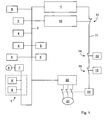
- Fig. 1 shows a block diagram for an elevator. It is provided a controller 1 for a designated 2 schematically illustrated elevator car.
- a motor 21 for driving the elevator car 2 is coupled to a bus 3 via a frequency converter 20.
- the controller 1 communicates the bus 3 by means of bus nodes with components which are exemplified as a floor switch 4, door contact 5, command transmitter 6 and safe actuator 7 for a door motor 8 of the elevator car 2.
- the controller 1 receives, via the bus 3, via the bus nodes, which form an interface for the components, signals of the components, such as the request for a trip to a certain floor via the command transmitter 6 in the elevator car 2.
- the door contacts 5 provide a signal as to whether the door of the corresponding floor is closed or open.
- the door contact 5 ' provides a signal as to whether the door of the elevator car 2 is closed or opened.
- the safe actuator 7 is used to drive the door motor 8 of the elevator car 2, which can be controlled by the controller 1 via corresponding signals that are sent via the bus 3.
- U ltra s chall- P ositionssysteme or USP systems are 9 or a two-channel system USP provided, which detect in each case via ultrasound the position of the elevator car 2 in the elevator shaft.
- Systems USS Schmersal are preferably used as USP systems 9, the function of which is described in the product catalog "Elevator Switching Systems - Elevator Positioning System USP" of 31.10.2007.
- the two USP systems 9 or the one two-channel USP system is a redundant determination of the position possible, which meets high security requirements by the two USP systems 9 or by the two-channel USP system determined position of the elevator car 2 is compared.
- the speed of the elevator car 2 in the elevator shaft can be determined via the time determined position of the elevator car 2 by the two USP systems 9 or a two-channel USP system as a derivation of the location function of the elevator car 2 in the elevator shaft after the time.
- multiple USP systems 9 may also be used as two. With two, however, the required redundancy already results. Analogously, the redundancy is also ensured with a two-channel USP system.
- a transmitter having two receivers and corresponding two channels may be used.
- a safety controller 10 is coupled as Can Safety Controller, which can receive the signals from floor switch 4, door contact 5, 5 ', command transmitter 6, safe actuator 7, door motor 8 and USP system 9 via the bus 3.
- the floor switch 4, door contact 5, 5 ', command 6, safe actuator 7, and USP system 9 can be referred to as sensors.
- the controller 1 is connected to a safety circuit 11, which the safety controller 10 can open via a (safety) switch 12.
- the safety controller 10 monitors the safety function of the elevator. If the security controller 10 determines an unsafe condition, such as the door contact 5 'indicates that the door of the elevator car 2 is open during travel between two floors, the (security) switch 12 is opened and the elevator is disabled or in a safe state. The opening of the safety circuit 11 leads to the operation of the (safety) switch 22, which shuts off the motor 21.
- a device 13 for monitoring the speed of the elevator car 2 can open a (safety) switch 14 independently of the safety controller 10 in order to access the safety circuit 11 open when, for example, a predetermined threshold speed of the elevator car 2 is exceeded.
- the device 13 for monitoring the speed of the elevator car 2 can be implemented independently of, or by, the USP systems 9.
- one or two limit switches 15 for monitoring the exceeding of a predetermined spatial position of the elevator car 2 can open a (safety) switch 16 independently of the safety controller 10 in order to open the safety circuit 11, for example when the elevator car 2 in the elevator shaft exceeds a predetermined end position at the lower or upper end of the elevator shaft.
- the limit switch (s) 15 may be implemented independently of, or through the USP systems 9 or the two-channel USP system.
- the controller 1 receives the feedback from the safety circuit 11 that the safety circuit 11 has been opened and the (safety) switch 22 has been actuated to stop the motor 21.
- a means is provided that the controller 1 reports the open safety circuit 11. This means can be realized, for example, by the (safety) switch 22.
- the controller 3 the information of the components, such as floor switch 4, door contact 5, command transmitter 6, safe actuator 7, door motor 8 and USP system 9, evaluates and determines that a shutdown by the safety controller 11 must be made (te). It can also be provided that the safety controller 11 forwards the signals received from the components to the controller 1.
- the controller 1 can provide improved diagnostics and maintenance by evaluating the signals of the individual components connected to the bus nodes.
- the safety controller 10 can redundantly determine the position of the elevator car 2 in the elevator shaft through the two USP systems 9 connected to the bus 3 or through the two-channel USP system.
- redundant speed information of the elevator car 2 can be determined by the safety controller 10 from the two USP systems 9 or the one dual-channel USP system, so that a "retrieval" in the area of the door zones of the elevator car 2 can take place, i.
- the safety controller 10 gives the safe actuator 7 on the elevator car 2 an enable signal, so that the door motor 8 may be actuated in the area of the door zone.
- the function of the door zone monitoring in the safety controller 10 can be integrated.
Abstract
Description
- Die Erfindung betrifft ein elektronisches Sicherheitssystem für einen Aufzug nach dem Oberbegriff des Anspruchs 1.
- Aus
EP 1 159 218 B1 ist ein elektronisches Sicherheitssystem für einen Aufzug bekannt, bei dem eine Sicherheitsabschaltung durchgeführt wird, wenn ein unsicherer Zustand festgestellt wird. Das elektronische Sicherheitssystem umfasst eine Sicherheitssteuereinrichtung und einen Kommunikations-Bus, der einen Austausch von Steuer- und Datensignalen zwischen einer auf einem Mikroprozessor basierenden Steuereinrichtung und verschiedenen Komponenten, die Busknoten umfassen, ermöglicht. Die Busknoten sind so ausgestaltet, dass sie eine Schnittstelle für Sensoren, Kontakte und Schalter bilden. Eine Sicherheitssteuereinrichtung verarbeitet die von den Busknoten empfangenen Daten und bestimmt, ob ein unsicherer Zustand besteht. Bei einem unsicheren Zustand schickt die Sicherheitsteuereinrichtung ein Stoppsignal an die Antriebs-und Bremseinheit des Aufzugs, wobei zudem ein Statussignal, das den unsicheren Zustand anzeigt, an die Steuereinrichtung gesendet wird. - Bei der aus
EP 1 159 218 B1 bekannten Sicherheitssteuereinrichtung soll die Steuereinrichtung des Aufzugs keine Informationen der Busknoten verarbeiten, sondern die Steuereinrichtung erhält schon die verarbeitete Information der Busknoten von der Sicherheitssteuereinrichtung, um eine schnellere Reaktion der Steuereinrichtung des Aufzugs zu ermöglichen. Die Sicherheitssteuereinrichtung übernimmt alleine die Sicherheitsaufgaben und ihr kommt eine elementare Rolle zu. - Aufgabe der Erfindung ist es, eine schnelle und sichere Ausgestaltung eines elektronischen Sicherheitssystems nach dem Oberbegriff des Anspruchs 1 zu erhalten, bei dem eine Entlastung einer Sicherheitskomponente erfolgt, was den Zugriff auf mehr Information(en) und eine erhöhte Sicherheit bei möglicher Verbesserung der Wartung zur Folge hat.
- Diese Aufgabe wird durch die Merkmale des Anspruchs 1 gelöst.
- Hierdurch wird eine Sicherheitskomponente wie ein Sicherheitscontroller entlastet, indem die Steuerung des Aufzugs gerade nicht von dem Sicherheitscontroller die Mitteilung erhält, dass eine Abschaltung bzw. eine Überführung in einen sicheren Zustand bei einem möglichen Gefahrenpotential durchgeführt wird bzw. wurde.
- Die Erfindung wird nachstehend anhand der in den beigefügten Abbildungen dargestellten Ausführungsbeispiele näher erläutert.
-
Fig. 1 zeigt schematisch ein Blockschaltbild für den Antrieb einer Aufzugskabine. -
Fig. 1 zeigt ein Blockschaltbild für einen Aufzug. Es ist eine Steuerung 1 für eine mit 2 bezeichnete schematisch dargestellte Aufzugskabine vorgesehen. - Ein Motor 21 zum Antrieb der Aufzugskabine 2 ist über einen Frequenzumrichter 20 mit einem Bus 3 gekoppelt.
- Die Steuerung 1 kommuniziert den Bus 3 mittels Busknoten mit Komponenten, die beispielhaft als Etagenschalter 4, Türkontakt 5, Befehlsgeber 6 und sicherer Aktor 7 für einen Türmotor 8 der Aufzugskabine 2 angegeben sind. Die Steuerung 1 empfängt über den Bus 3 über die Busknoten, die eine Schnittstelle für die Komponenten bilden, Signale der Komponenten, wie zum Beispiel die Anforderung einer Fahrt zu einer bestimmten Etage über den Befehlsgeber 6 in der Aufzugskabine 2.
- Ferner werden Signale von Etagenschaltern 4 erhalten, die Rückschlüsse darauf zu lassen, in welcher Etage sich die Aufzugskabine 2 befindet. Die Türkontakte 5 liefern ein Signal, ob die Tür der entsprechenden Etage geschlossen oder geöffnet ist. Der Türkontakt 5' liefert ein Signal, ob die Tür der Aufzugskabine 2 geschlossen oder geöffnet ist. Der sichere Aktor 7 dient zum Antrieb des Türmotors 8 der Aufzugskabine 2, der von der Steuerung 1 über entsprechende Signale, die über den Bus 3 gesendet werden, gesteuert werden kann.
- Ferner sind mindestens zwei Ultraschall-Positionssysteme bzw. USP-Systeme 9 oder ein zweikanaliges USP-System vorgesehen, die jeweils über Ultraschall die Position der Aufzugskabine 2 im Aufzugsschacht ermitteln. Als USP-Systeme 9 werden vorzugsweise Systeme der Firma Schmersal verwendet, deren Funktion im Produktkatalog "Aufzugsschaltgeräte - Aufzugs-Positionssystem USP" vom 31.10.2007 beschrieben ist. Über die beiden USP-Systeme 9 oder das eine zweikanalige USP-System ist eine redundante Ermittlung der Position möglich, die hohen Sicherheitsanforderungen genügt, indem die durch die beiden USP-Systeme 9 oder die durch das eine zweikanalige USP-System ermittelte Position der Aufzugskabine 2 verglichen wird. Ferner ist über die über die Zeit ermittelte Position der Aufzugskabine 2 durch die beiden USP-Systeme 9 oder das eine zweikanalige USP-System die Geschwindigkeit der Aufzugskabine 2 im Aufzugsschacht bestimmbar als Ableitung der Ortsfunktion der Aufzugskabine 2 im Aufzugsschacht nach der Zeit. Es versteht sich, dass auch mehrere USP-Systeme 9 als zwei verwendet werden können. Bei zweien ergibt sich jedoch schon die geforderte Redundanz. Analog ist mit einem zweikanaligen USP-System ebenfalls die Redundanz gewahrt. Bei dem zweikanaligen USP-System kann beispielsweise ein Sender mit zwei Empfängern und entsprechenden zwei Kanälen verwendet werden.
- An den Bus 3 ist ein Sicherheitscontroller 10 als Can-Safety-Controller angekoppelt, der die Signale von Etagenschalter 4, Türkontakt 5, 5', Befehlsgeber 6, sicherem Aktor 7, Türmotor 8 und USP-System 9 über den Bus 3 empfangen kann. Der Etagenschalter 4, Türkontakt 5, 5', Befehlsgeber 6, sicherer Aktor 7, und USP-System 9 können insoweit als Sensoren bezeichnet werden.
- Die Steuerung 1 ist mit einem Sicherheitskreis 11 verbunden, den der Sicherheitscontroller 10 über einen (Sicherheits-)Schalter 12 öffnen kann. Der Sicherheitscontroller 10 überwacht die Sicherheitsfunktion des Aufzugs. Stellt der Sicherheitscontroller 10 einen unsicheren Zustand fest, wie bspw., dass der Türkontakt 5' anzeigt, dass die Tür der Aufzugskabine 2 während der Fahrt zwischen zwei Etagen offen ist, wird der (Sicherheits-)Schalter 12 geöffnet und der Aufzug außer Betrieb gesetzt bzw. in einen sicheren Zustand verfahren. Die Öffnung des Sicherheitskreises 11 führt zur Betätigung des (Sicherheits-)Schalters 22, der den Motor 21 abstellt.
- Es kann vorgesehen sein, dass eine Einrichtung 13 zur Überwachung der Geschwindigkeit der Aufzugskabine 2 einen (Sicherheits-)Schalter 14 unabhängig von dem Sicherheitscontroller 10 öffnen kann, um den Sicherheitskreis 11 zu öffnen, wenn beispielsweise ein vorbestimmter Schwellenwert der Geschwindigkeit der Aufzugskabine 2 überschritten wird. Die Einrichtung 13 zur Überwachung der Geschwindigkeit der Aufzugskabine 2 kann unabhängig von den USP-Systemen 9, oder durch diese realisiert sein.
- Es kann vorgesehen sein, dass ein oder zwei Endschalter 15 zur Überwachung des Überschreitens einer vorbestimmten Ortsposition der Aufzugskabine 2 einen (Sicherheits-)Schalter 16 unabhängig von dem Sicherheitscontroller 10 öffnen können, um den Sicherheitskreis 11 zu öffnen, wenn beispielsweise die Aufzugskabine 2 im Aufzugsschacht eine vorbestimmte Endposition am unteren oder oberen Ende des Aufzugsschacht überschreitet. Der bzw. die Endschalter 15 können unabhängig von den USP-Systemen 9 bzw. dem zweikanaligen USP-System, oder durch diese realisiert sein.
- Bei einer Abschaltung des Motors 21 erhält die Steuerung 1 von dem Sicherheitskreis 11 die Rückmeldung, dass der Sicherheitskreis 11 geöffnet wurde, und der (Sicherheits-)Schalter 22 zum Stoppen des Motors 21 betätigt wurde. Dazu ist ein Mittel vorgesehen, dass der Steuerung 1 den geöffneten Sicherheitskreis 11 meldet. Dieses Mittel kann beispielsweise durch den (Sicherheits-)Schalter 22 realisiert sein. Es kann alternativ oder zusätzlich vorgesehen sein, dass die Steuerung 3 die Information der Komponenten, wie Etagenschalter 4, Türkontakt 5, Befehlsgeber 6, sicherer Aktor 7, Türmotor 8 und USP-System 9, auswertet und feststellt, dass eine Abschaltung durch den Sicherheitscontroller 11 vorgenommen werden muss(te). Es kann auch vorgesehen sein, dass der Sicherheitscontroller 11 die von den Komponenten empfangenen Signale an die Steuerung 1 weiterleitet.
- Die Steuerung 1 kann durch die Auswertung der Signale der einzelnen an die Busknoten angeschlossenen Komponenten eine verbesserte Diagnose- und Wartungsmöglichkeit liefern.
- Der Sicherheitscontroller 10 kann beispielsweise durch die zwei an den Bus 3 angeschlossenen USP-Systeme 9 oder durch das eine zweikanalige USP-System die Position der Aufzugskabine 2 in dem Aufzugsschacht redundant ermitteln.
- Wenn nun eine Etagentür des Aufzugsschachts nicht richtig schließt und der Türkontakt 5 nicht geschlossen ist, ist man in der Lage, die Aufzugskabine 2 oberhalb oder unterhalb der gestörten Tür, deren Türkontakt 5 nicht geschlossen ist, zu bewegen. Die Redundanz der Ortsbestimmung der Aufzugskabine 2 durch die beiden USP-Systeme 9 oder das eine zweikanalige USP-System wird als sichere Information genommen, bei der eine Abschaltung des Aufzugs solange nicht erfolgt, wie die Aufzugskabine 2 nicht in den Etagenbereich mit der gestörten Tür, d.h. dem geöffneten Türkontakt 5, gelangt. Die Verfügbarkeit des Aufzuges wird verbessert.
- Ferner kann vorgesehen sein, dass aus den zwei USP-Systemen 9 oder dem einen zweikanaligen USP-System redundant eine Geschwindigkeitsinformation der Aufzugskabine 2 vom Sicherheitscontroller 10 bestimmbar ist, damit eine "Nachholung" im Bereich der Türzonen der Aufzugskabine 2 erfolgen kann, d.h. der Sicherheitscontroller 10 gibt im Bereich der Türzonen dem sicheren Aktor 7 auf der Aufzugskabine 2 ein Freigabesignal, damit der Türmotor 8 im Bereich der Türzone betätigt werden darf. Hierdurch kann die Funktion der Türzonenüberwachung im Sicherheitscontroller 10 integriert werden.
Claims (3)
- Elektronisches Sicherheitssystem für einen Aufzug mit einer Steuerung (1), die mit einem Motor (21) zum Antrieb einer Aufzugskabine (2) gekoppelt ist, umfassend einen Sicherheitscontroller (10), einen Bus (3), über den die Steuerung (1) mit Busknoten, die Daten von mindestens einem Sensor (4, 5, 5', 6, 7, 9) empfangen, in Kommunikation steht, dadurch gekennzeichnet, dass die Steuerung (1) mit einem Sicherheitskreis (11) in Kommunikation steht, der durch den Sicherheitscontroller (10) in einen geöffneten Zustand bringbar ist, wodurch der Motor (21) abgeschaltet ist, und der Sicherheitskreis (11) ein Mittel aufweist, das der Steuerung (1) eine Abschaltung des Motors (21) mitteilt, oder eine Abschaltung des Motors (21) durch die Steuerung (1) aufgrund der von den Busknoten der Steuerung (1) übermittelten Daten detektierbar ist.
- Elektronisches Sicherheitssystem nach Anspruch 1, dadurch gekennzeichnet, dass als Sensor (4, 5, 5', 6, 7, 9) mindestens zwei USP-Systeme (9) oder ein zweikanaliges USP-System vorgesehen sind, mit denen redundant eine Positionsbestimmung der Aufzugskabine (2) durchführbar ist.
- Elektronisches Sicherheitssystem nach Anspruch 1 oder 2, dadurch gekennzeichnet, dass ein sicherer Aktor (7) vorgesehen ist, dem ein Freigabesignal zum Antrieb eines Türmotors (8) der Aufzugskabine (2) übermittelbar ist, wenn über mindestens zwei USP-Systeme (9) oder ein zweikanaliges USP-System als Sensor (4, 5, 5', 6, 7, 9) festgestellt wird, dass sich die Aufzugskabine (2) im Bereich einer Türzone befindet und eine vorbestimmte Geschwindigkeit der Aufzugskabine (2) nicht überschritten wird.
Applications Claiming Priority (1)
| Application Number | Priority Date | Filing Date | Title |
|---|---|---|---|
| DE102009037347A DE102009037347A1 (de) | 2009-08-14 | 2009-08-14 | Elektronisches Sicherheitssystem für einen Aufzug |
Publications (2)
| Publication Number | Publication Date |
|---|---|
| EP2284110A1 true EP2284110A1 (de) | 2011-02-16 |
| EP2284110B1 EP2284110B1 (de) | 2013-06-26 |
Family
ID=43064396
Family Applications (1)
| Application Number | Title | Priority Date | Filing Date |
|---|---|---|---|
| EP10008399.7A Revoked EP2284110B1 (de) | 2009-08-14 | 2010-08-12 | Elektronisches Sicherheitsystem für einen Aufzug |
Country Status (4)
| Country | Link |
|---|---|
| US (1) | US8413765B2 (de) |
| EP (1) | EP2284110B1 (de) |
| JP (1) | JP5300802B2 (de) |
| DE (1) | DE102009037347A1 (de) |
Families Citing this family (18)
| Publication number | Priority date | Publication date | Assignee | Title |
|---|---|---|---|---|
| KR20120023105A (ko) * | 2009-06-22 | 2012-03-12 | 미쓰비시덴키 가부시키가이샤 | 엘리베이터 장치 |
| EP2616376B1 (de) * | 2010-09-13 | 2020-11-18 | Otis Elevator Company | Sicherheitssystem und -verfahren für einen aufzug |
| FI122474B (fi) * | 2010-12-01 | 2012-02-15 | Kone Corp | Hissin turvakytkentä sekä menetelmä hissin turvakytkennän toiminnallisen poikkeaman tunnistamiseksi |
| EP2567928B1 (de) | 2011-09-06 | 2013-09-11 | Cedes AG | Sensor, Sicherungsvorrichtung sowie Aufzugvorrichtung |
| EP2604563B1 (de) * | 2011-12-12 | 2015-10-21 | Cedes AG | Sicherungsvorrichtung Antriebsvorrichtung und Aufzugvorrichtung |
| EP2604566B1 (de) | 2011-12-12 | 2014-03-26 | Cedes AG | Sicherungsvorrichtung sowie Aufzugvorrichtung |
| US10227208B2 (en) | 2011-12-12 | 2019-03-12 | Cedes Ag | Safety apparatus for an elevator |
| WO2014124780A1 (de) * | 2013-02-12 | 2014-08-21 | Inventio Ag | Sicherheitskreis- überwachung mit wechselspannung |
| PL3080030T3 (pl) * | 2013-12-09 | 2018-08-31 | Inventio Ag | Obwód bezpieczeństwa dla instalacji dźwigowej |
| EP3083478B1 (de) * | 2013-12-18 | 2022-06-08 | Inventio AG | Sicherheitssystem für eine aufzugsanlage |
| CN107148392B (zh) | 2014-10-21 | 2020-09-11 | 因温特奥股份公司 | 具有非中心的电子安全系统的电梯 |
| CN107709209B (zh) * | 2015-06-15 | 2019-09-17 | 三菱电机株式会社 | 电梯安全系统 |
| US10315886B2 (en) | 2016-04-11 | 2019-06-11 | Otis Elevator Company | Electronic safety actuation device with a power assembly, magnetic brake and electromagnetic component |
| EP3243784B1 (de) * | 2016-05-11 | 2019-01-30 | Kone Corporation | Anordnung zur freigabe der betriebsbremse eines aufzugs |
| IL247342A (en) * | 2016-08-18 | 2017-10-31 | Yoram Madar | Detection and control of an arrest prevented an elevator |
| ES2844381T3 (es) | 2017-05-17 | 2021-07-22 | Kone Corp | Un procedimiento y sistema para generar datos de mantenimiento de un sistema de puertas de ascensor |
| US11078045B2 (en) * | 2018-05-15 | 2021-08-03 | Otis Elevator Company | Electronic safety actuator for lifting a safety wedge of an elevator |
| EP3587323A1 (de) * | 2018-06-22 | 2020-01-01 | Otis Elevator Company | Aufzugsystem |
Citations (6)
| Publication number | Priority date | Publication date | Assignee | Title |
|---|---|---|---|---|
| WO2000051929A1 (en) * | 1999-03-04 | 2000-09-08 | Otis Elevator Company | Electronic safety system for elevators |
| US20050098390A1 (en) * | 2003-11-11 | 2005-05-12 | Philipp Angst | Elevator installation and monitoring system for an elevator installation |
| EP1864935A1 (de) * | 2005-03-31 | 2007-12-12 | Mitsubishi Denki Kabushiki Kaisha | Aufzugsvorrichtung |
| WO2008081074A1 (en) * | 2007-01-03 | 2008-07-10 | Kone Corporation | Elevator safety device |
| WO2009073025A1 (en) * | 2007-12-05 | 2009-06-11 | Otis Elevator Company | Control strategy for operating two elevator cars in a single hoistway |
| WO2010072658A1 (de) * | 2008-12-26 | 2010-07-01 | Inventio Ag | Aufzugsanlage mit einer sicherheitseinrichtung |
Family Cites Families (17)
| Publication number | Priority date | Publication date | Assignee | Title |
|---|---|---|---|---|
| US4785914A (en) * | 1987-06-19 | 1988-11-22 | Westinghouse Electric Corp. | Elevator system leveling safeguard control and method |
| US4750591A (en) * | 1987-07-10 | 1988-06-14 | Otis Elevator Company | Elevator car door and motion sequence monitoring apparatus and method |
| US5107964A (en) * | 1990-05-07 | 1992-04-28 | Otis Elevator Company | Separate elevator door chain |
| DE4208173A1 (de) * | 1991-06-03 | 1992-12-10 | Otis Elevator Co | Verfahren und vorrichtung zum messen der absolutstellung einer stehenden fahrstuhlkabine |
| DE19903645C2 (de) * | 1999-01-29 | 2002-07-18 | Schmersal K A Gmbh & Co | Einrichtung zur Positionserfassung |
| EP1090870B1 (de) * | 1999-10-08 | 2007-07-04 | Inventio Ag | Sicherheitskreis für eine Aufzugsanlage |
| US6554107B2 (en) * | 2001-09-27 | 2003-04-29 | Mitsubishi Denki Kabushiki Kaisha | Elevator system |
| JP4553535B2 (ja) * | 2001-09-28 | 2010-09-29 | 三菱電機株式会社 | エレベータ装置 |
| US7493991B2 (en) * | 2003-05-30 | 2009-02-24 | Otis Elevator Company | Electromagnetic/ultrasonic roll-calling/answering (EURA) system for elevator positioning |
| MXPA05013517A (es) * | 2003-06-30 | 2006-03-09 | Inventio Ag | Sistema de seguridad de instalacion de elevador. |
| DE102004009250A1 (de) * | 2004-02-20 | 2005-09-08 | K.A. Schmersal Holding Kg | Sicherheitsüberwachungseinrichtung für eine Aufzugskabine |
| FI119878B (fi) * | 2005-02-04 | 2009-04-30 | Kone Corp | Järjestelmä ja menetelmä hissin turvallisuuden parantamiseksi |
| JP4831995B2 (ja) * | 2005-05-11 | 2011-12-07 | 三菱電機株式会社 | エレベータの安全制御装置 |
| FI20070486A (fi) * | 2007-01-03 | 2008-07-04 | Kone Corp | Hissin turvajärjestely |
| FI119508B (fi) * | 2007-04-03 | 2008-12-15 | Kone Corp | Vikaturvallinen tehonohjauslaitteisto |
| EP2022742B1 (de) * | 2007-08-07 | 2014-06-25 | ThyssenKrupp Elevator AG | Aufzugsystem |
| EP2448853B1 (de) * | 2009-07-02 | 2019-10-09 | Otis Elevator Company | Rettungssystem für einen aufzug |
-
2009
- 2009-08-14 DE DE102009037347A patent/DE102009037347A1/de not_active Withdrawn
-
2010
- 2010-08-12 EP EP10008399.7A patent/EP2284110B1/de not_active Revoked
- 2010-08-12 JP JP2010181050A patent/JP5300802B2/ja not_active Expired - Fee Related
- 2010-08-13 US US12/855,986 patent/US8413765B2/en active Active
Patent Citations (7)
| Publication number | Priority date | Publication date | Assignee | Title |
|---|---|---|---|---|
| WO2000051929A1 (en) * | 1999-03-04 | 2000-09-08 | Otis Elevator Company | Electronic safety system for elevators |
| EP1159218B1 (de) | 1999-03-04 | 2006-07-12 | Otis Elevator Company | Elektronische sicherheitsschaltung für aufzüge |
| US20050098390A1 (en) * | 2003-11-11 | 2005-05-12 | Philipp Angst | Elevator installation and monitoring system for an elevator installation |
| EP1864935A1 (de) * | 2005-03-31 | 2007-12-12 | Mitsubishi Denki Kabushiki Kaisha | Aufzugsvorrichtung |
| WO2008081074A1 (en) * | 2007-01-03 | 2008-07-10 | Kone Corporation | Elevator safety device |
| WO2009073025A1 (en) * | 2007-12-05 | 2009-06-11 | Otis Elevator Company | Control strategy for operating two elevator cars in a single hoistway |
| WO2010072658A1 (de) * | 2008-12-26 | 2010-07-01 | Inventio Ag | Aufzugsanlage mit einer sicherheitseinrichtung |
Also Published As
| Publication number | Publication date |
|---|---|
| JP2011037635A (ja) | 2011-02-24 |
| US20110036668A1 (en) | 2011-02-17 |
| EP2284110B1 (de) | 2013-06-26 |
| JP5300802B2 (ja) | 2013-09-25 |
| US8413765B2 (en) | 2013-04-09 |
| DE102009037347A1 (de) | 2011-02-17 |
Similar Documents
| Publication | Publication Date | Title |
|---|---|---|
| EP2284110B1 (de) | Elektronisches Sicherheitsystem für einen Aufzug | |
| EP3224174B1 (de) | Aufzuganlage mit einer mehrzahl von fahrkörben sowie einem dezentralen sicherheitssystem | |
| EP3230189B1 (de) | Aufzugsystem mit sicherheitsüberwachungssystem mit einer master-slave-hierarchie | |
| EP3145787B1 (de) | Schienenfahrzeug | |
| EP3313710B1 (de) | System und verfahren zur automatischen kurzschlussbeseitigung in einem energiebus | |
| DE102013020177A1 (de) | Kraftfahrzeug | |
| EP1848619B1 (de) | Bremsvorrichtung für ein schienenfahrzeug | |
| EP3080030B1 (de) | Sicherheitskreis für eine aufzugsanlage | |
| EP2139803A1 (de) | Verfahren zum steuern einer lastbewegungsvorrichtung und steuerung einer lastbewegungsvorrichtung | |
| EP3385934A1 (de) | Vorrichtung für die steuerung eines sicherheitsrelevanten vorganges, verfahren zum testen der funktionsfähigkeit der vorrichtung, sowie kraftfahrzeug mit der vorrichtung | |
| EP3676141A1 (de) | Elektro-mechanischer bremsaktuator mit interner leistungselektronik und energiespeicher | |
| DE102014013173A1 (de) | Verfahren zum zumindest teilautonomen Betrieb eines Fahrzeugs und Fahrerassistenzsystem | |
| WO2021197555A1 (de) | Bremssystem mit wenigstens zwei energiequellen | |
| EP3781464B1 (de) | Förderanlage mit einem förderwagen | |
| EP3191357B1 (de) | Förderanlage mit sicherheitsfunktion | |
| DE102015211587A1 (de) | Steueranordnung für ein Fahrzeug | |
| DE102017208888A1 (de) | Verfahren zur sicheren Durchführung einer Zugtaufe | |
| EP2021203B1 (de) | Anordnung mit einer vielzahl an elektrischen schaltern, insbesondere für eine magnetschwebebahnstrecke | |
| EP3038868B2 (de) | Verfahren zum bremsen eines schienenfahrzeugs und steuer- und/oder regeleinrichtung für ein bremssystem | |
| EP3622674B1 (de) | Verfahren zu übermittlung mindestens eines steuerbefehls und steuereinrichtung | |
| DE102018209495B3 (de) | Steuerungssystem zum autonomen Betreiben eines Fahrzeugs | |
| DE102008008449A1 (de) | Elektrische Presse | |
| EP3924796A1 (de) | Verfahren und system zur begrenzung und überwachung mindestens eines arbeitsbereichs für zumindest ein autonom betriebenes fahrzeug | |
| WO2019011380A1 (de) | Verfahren zum verhindern von kritischen situationen eines gespanns, wobei ein abstand zwischen stellen vom gespann bestimmt wird, fahrerassistenzsystem und kraftfahrzeug | |
| DE102023200911B3 (de) | Verfahren sowie Assistenzsystem zum Steuern eines Fahrzeuges |
Legal Events
| Date | Code | Title | Description |
|---|---|---|---|
| PUAI | Public reference made under article 153(3) epc to a published international application that has entered the european phase |
Free format text: ORIGINAL CODE: 0009012 |
|
| AK | Designated contracting states |
Kind code of ref document: A1 Designated state(s): AL AT BE BG CH CY CZ DE DK EE ES FI FR GB GR HR HU IE IS IT LI LT LU LV MC MK MT NL NO PL PT RO SE SI SK SM TR |
|
| AX | Request for extension of the european patent |
Extension state: BA ME RS |
|
| 17P | Request for examination filed |
Effective date: 20110808 |
|
| 17Q | First examination report despatched |
Effective date: 20120214 |
|
| GRAP | Despatch of communication of intention to grant a patent |
Free format text: ORIGINAL CODE: EPIDOSNIGR1 |
|
| GRAS | Grant fee paid |
Free format text: ORIGINAL CODE: EPIDOSNIGR3 |
|
| GRAA | (expected) grant |
Free format text: ORIGINAL CODE: 0009210 |
|
| AK | Designated contracting states |
Kind code of ref document: B1 Designated state(s): AL AT BE BG CH CY CZ DE DK EE ES FI FR GB GR HR HU IE IS IT LI LT LU LV MC MK MT NL NO PL PT RO SE SI SK SM TR |
|
| REG | Reference to a national code |
Ref country code: GB Ref legal event code: FG4D Free format text: NOT ENGLISH |
|
| REG | Reference to a national code |
Ref country code: CH Ref legal event code: EP |
|
| REG | Reference to a national code |
Ref country code: AT Ref legal event code: REF Ref document number: 618606 Country of ref document: AT Kind code of ref document: T Effective date: 20130715 |
|
| REG | Reference to a national code |
Ref country code: IE Ref legal event code: FG4D Free format text: LANGUAGE OF EP DOCUMENT: GERMAN |
|
| REG | Reference to a national code |
Ref country code: DE Ref legal event code: R096 Ref document number: 502010003768 Country of ref document: DE Effective date: 20130822 |
|
| PG25 | Lapsed in a contracting state [announced via postgrant information from national office to epo] |
Ref country code: LT Free format text: LAPSE BECAUSE OF FAILURE TO SUBMIT A TRANSLATION OF THE DESCRIPTION OR TO PAY THE FEE WITHIN THE PRESCRIBED TIME-LIMIT Effective date: 20130626 Ref country code: FI Free format text: LAPSE BECAUSE OF FAILURE TO SUBMIT A TRANSLATION OF THE DESCRIPTION OR TO PAY THE FEE WITHIN THE PRESCRIBED TIME-LIMIT Effective date: 20130626 Ref country code: NO Free format text: LAPSE BECAUSE OF FAILURE TO SUBMIT A TRANSLATION OF THE DESCRIPTION OR TO PAY THE FEE WITHIN THE PRESCRIBED TIME-LIMIT Effective date: 20130926 Ref country code: SE Free format text: LAPSE BECAUSE OF FAILURE TO SUBMIT A TRANSLATION OF THE DESCRIPTION OR TO PAY THE FEE WITHIN THE PRESCRIBED TIME-LIMIT Effective date: 20130626 Ref country code: GR Free format text: LAPSE BECAUSE OF FAILURE TO SUBMIT A TRANSLATION OF THE DESCRIPTION OR TO PAY THE FEE WITHIN THE PRESCRIBED TIME-LIMIT Effective date: 20130927 Ref country code: SI Free format text: LAPSE BECAUSE OF FAILURE TO SUBMIT A TRANSLATION OF THE DESCRIPTION OR TO PAY THE FEE WITHIN THE PRESCRIBED TIME-LIMIT Effective date: 20130626 |
|
| REG | Reference to a national code |
Ref country code: LT Ref legal event code: MG4D |
|
| PG25 | Lapsed in a contracting state [announced via postgrant information from national office to epo] |
Ref country code: BG Free format text: LAPSE BECAUSE OF FAILURE TO SUBMIT A TRANSLATION OF THE DESCRIPTION OR TO PAY THE FEE WITHIN THE PRESCRIBED TIME-LIMIT Effective date: 20130926 Ref country code: HR Free format text: LAPSE BECAUSE OF FAILURE TO SUBMIT A TRANSLATION OF THE DESCRIPTION OR TO PAY THE FEE WITHIN THE PRESCRIBED TIME-LIMIT Effective date: 20130626 |
|
| REG | Reference to a national code |
Ref country code: NL Ref legal event code: VDEP Effective date: 20130626 |
|
| PG25 | Lapsed in a contracting state [announced via postgrant information from national office to epo] |
Ref country code: LV Free format text: LAPSE BECAUSE OF FAILURE TO SUBMIT A TRANSLATION OF THE DESCRIPTION OR TO PAY THE FEE WITHIN THE PRESCRIBED TIME-LIMIT Effective date: 20130626 |
|
| PG25 | Lapsed in a contracting state [announced via postgrant information from national office to epo] |
Ref country code: SK Free format text: LAPSE BECAUSE OF FAILURE TO SUBMIT A TRANSLATION OF THE DESCRIPTION OR TO PAY THE FEE WITHIN THE PRESCRIBED TIME-LIMIT Effective date: 20130626 Ref country code: EE Free format text: LAPSE BECAUSE OF FAILURE TO SUBMIT A TRANSLATION OF THE DESCRIPTION OR TO PAY THE FEE WITHIN THE PRESCRIBED TIME-LIMIT Effective date: 20130626 Ref country code: PT Free format text: LAPSE BECAUSE OF FAILURE TO SUBMIT A TRANSLATION OF THE DESCRIPTION OR TO PAY THE FEE WITHIN THE PRESCRIBED TIME-LIMIT Effective date: 20131028 Ref country code: IS Free format text: LAPSE BECAUSE OF FAILURE TO SUBMIT A TRANSLATION OF THE DESCRIPTION OR TO PAY THE FEE WITHIN THE PRESCRIBED TIME-LIMIT Effective date: 20131026 Ref country code: CZ Free format text: LAPSE BECAUSE OF FAILURE TO SUBMIT A TRANSLATION OF THE DESCRIPTION OR TO PAY THE FEE WITHIN THE PRESCRIBED TIME-LIMIT Effective date: 20130626 Ref country code: CY Free format text: LAPSE BECAUSE OF FAILURE TO SUBMIT A TRANSLATION OF THE DESCRIPTION OR TO PAY THE FEE WITHIN THE PRESCRIBED TIME-LIMIT Effective date: 20130918 |
|
| BERE | Be: lapsed |
Owner name: K.A. SCHMERSAL HOLDING G.M.B.H. & CO. KG Effective date: 20130831 |
|
| PG25 | Lapsed in a contracting state [announced via postgrant information from national office to epo] |
Ref country code: RO Free format text: LAPSE BECAUSE OF FAILURE TO SUBMIT A TRANSLATION OF THE DESCRIPTION OR TO PAY THE FEE WITHIN THE PRESCRIBED TIME-LIMIT Effective date: 20130626 Ref country code: PL Free format text: LAPSE BECAUSE OF FAILURE TO SUBMIT A TRANSLATION OF THE DESCRIPTION OR TO PAY THE FEE WITHIN THE PRESCRIBED TIME-LIMIT Effective date: 20130626 Ref country code: NL Free format text: LAPSE BECAUSE OF FAILURE TO SUBMIT A TRANSLATION OF THE DESCRIPTION OR TO PAY THE FEE WITHIN THE PRESCRIBED TIME-LIMIT Effective date: 20130626 Ref country code: ES Free format text: LAPSE BECAUSE OF FAILURE TO SUBMIT A TRANSLATION OF THE DESCRIPTION OR TO PAY THE FEE WITHIN THE PRESCRIBED TIME-LIMIT Effective date: 20131007 |
|
| PLBI | Opposition filed |
Free format text: ORIGINAL CODE: 0009260 |
|
| PG25 | Lapsed in a contracting state [announced via postgrant information from national office to epo] |
Ref country code: CY Free format text: LAPSE BECAUSE OF FAILURE TO SUBMIT A TRANSLATION OF THE DESCRIPTION OR TO PAY THE FEE WITHIN THE PRESCRIBED TIME-LIMIT Effective date: 20130626 |
|
| PLAX | Notice of opposition and request to file observation + time limit sent |
Free format text: ORIGINAL CODE: EPIDOSNOBS2 |
|
| 26 | Opposition filed |
Opponent name: INVENTIO AG Effective date: 20140326 |
|
| PG25 | Lapsed in a contracting state [announced via postgrant information from national office to epo] |
Ref country code: DK Free format text: LAPSE BECAUSE OF FAILURE TO SUBMIT A TRANSLATION OF THE DESCRIPTION OR TO PAY THE FEE WITHIN THE PRESCRIBED TIME-LIMIT Effective date: 20130626 Ref country code: MC Free format text: LAPSE BECAUSE OF FAILURE TO SUBMIT A TRANSLATION OF THE DESCRIPTION OR TO PAY THE FEE WITHIN THE PRESCRIBED TIME-LIMIT Effective date: 20130626 |
|
| REG | Reference to a national code |
Ref country code: IE Ref legal event code: MM4A |
|
| PG25 | Lapsed in a contracting state [announced via postgrant information from national office to epo] |
Ref country code: BE Free format text: LAPSE BECAUSE OF NON-PAYMENT OF DUE FEES Effective date: 20130831 |
|
| REG | Reference to a national code |
Ref country code: DE Ref legal event code: R026 Ref document number: 502010003768 Country of ref document: DE Effective date: 20140326 |
|
| PG25 | Lapsed in a contracting state [announced via postgrant information from national office to epo] |
Ref country code: IE Free format text: LAPSE BECAUSE OF NON-PAYMENT OF DUE FEES Effective date: 20130812 |
|
| PLBB | Reply of patent proprietor to notice(s) of opposition received |
Free format text: ORIGINAL CODE: EPIDOSNOBS3 |
|
| REG | Reference to a national code |
Ref country code: CH Ref legal event code: PL |
|
| PG25 | Lapsed in a contracting state [announced via postgrant information from national office to epo] |
Ref country code: CH Free format text: LAPSE BECAUSE OF NON-PAYMENT OF DUE FEES Effective date: 20140831 Ref country code: LI Free format text: LAPSE BECAUSE OF NON-PAYMENT OF DUE FEES Effective date: 20140831 |
|
| PG25 | Lapsed in a contracting state [announced via postgrant information from national office to epo] |
Ref country code: SM Free format text: LAPSE BECAUSE OF FAILURE TO SUBMIT A TRANSLATION OF THE DESCRIPTION OR TO PAY THE FEE WITHIN THE PRESCRIBED TIME-LIMIT Effective date: 20130626 |
|
| PG25 | Lapsed in a contracting state [announced via postgrant information from national office to epo] |
Ref country code: MT Free format text: LAPSE BECAUSE OF FAILURE TO SUBMIT A TRANSLATION OF THE DESCRIPTION OR TO PAY THE FEE WITHIN THE PRESCRIBED TIME-LIMIT Effective date: 20130626 Ref country code: TR Free format text: LAPSE BECAUSE OF FAILURE TO SUBMIT A TRANSLATION OF THE DESCRIPTION OR TO PAY THE FEE WITHIN THE PRESCRIBED TIME-LIMIT Effective date: 20130626 |
|
| PG25 | Lapsed in a contracting state [announced via postgrant information from national office to epo] |
Ref country code: MK Free format text: LAPSE BECAUSE OF FAILURE TO SUBMIT A TRANSLATION OF THE DESCRIPTION OR TO PAY THE FEE WITHIN THE PRESCRIBED TIME-LIMIT Effective date: 20130626 Ref country code: LU Free format text: LAPSE BECAUSE OF NON-PAYMENT OF DUE FEES Effective date: 20130812 Ref country code: HU Free format text: LAPSE BECAUSE OF FAILURE TO SUBMIT A TRANSLATION OF THE DESCRIPTION OR TO PAY THE FEE WITHIN THE PRESCRIBED TIME-LIMIT; INVALID AB INITIO Effective date: 20100812 |
|
| APAH | Appeal reference modified |
Free format text: ORIGINAL CODE: EPIDOSCREFNO |
|
| APBM | Appeal reference recorded |
Free format text: ORIGINAL CODE: EPIDOSNREFNO |
|
| APBP | Date of receipt of notice of appeal recorded |
Free format text: ORIGINAL CODE: EPIDOSNNOA2O |
|
| APBQ | Date of receipt of statement of grounds of appeal recorded |
Free format text: ORIGINAL CODE: EPIDOSNNOA3O |
|
| REG | Reference to a national code |
Ref country code: FR Ref legal event code: PLFP Year of fee payment: 7 |
|
| REG | Reference to a national code |
Ref country code: AT Ref legal event code: MM01 Ref document number: 618606 Country of ref document: AT Kind code of ref document: T Effective date: 20150812 |
|
| PG25 | Lapsed in a contracting state [announced via postgrant information from national office to epo] |
Ref country code: AT Free format text: LAPSE BECAUSE OF NON-PAYMENT OF DUE FEES Effective date: 20150812 |
|
| REG | Reference to a national code |
Ref country code: FR Ref legal event code: PLFP Year of fee payment: 8 |
|
| REG | Reference to a national code |
Ref country code: FR Ref legal event code: PLFP Year of fee payment: 9 |
|
| PG25 | Lapsed in a contracting state [announced via postgrant information from national office to epo] |
Ref country code: AL Free format text: LAPSE BECAUSE OF FAILURE TO SUBMIT A TRANSLATION OF THE DESCRIPTION OR TO PAY THE FEE WITHIN THE PRESCRIBED TIME-LIMIT Effective date: 20130626 |
|
| PGFP | Annual fee paid to national office [announced via postgrant information from national office to epo] |
Ref country code: FR Payment date: 20190822 Year of fee payment: 10 Ref country code: IT Payment date: 20190829 Year of fee payment: 10 |
|
| REG | Reference to a national code |
Ref country code: DE Ref legal event code: R064 Ref document number: 502010003768 Country of ref document: DE Ref country code: DE Ref legal event code: R103 Ref document number: 502010003768 Country of ref document: DE |
|
| APBU | Appeal procedure closed |
Free format text: ORIGINAL CODE: EPIDOSNNOA9O |
|
| PGFP | Annual fee paid to national office [announced via postgrant information from national office to epo] |
Ref country code: GB Payment date: 20190821 Year of fee payment: 10 |
|
| PGFP | Annual fee paid to national office [announced via postgrant information from national office to epo] |
Ref country code: DE Payment date: 20191029 Year of fee payment: 10 |
|
| RDAF | Communication despatched that patent is revoked |
Free format text: ORIGINAL CODE: EPIDOSNREV1 |
|
| RDAG | Patent revoked |
Free format text: ORIGINAL CODE: 0009271 |
|
| STAA | Information on the status of an ep patent application or granted ep patent |
Free format text: STATUS: PATENT REVOKED |
|
| REG | Reference to a national code |
Ref country code: FI Ref legal event code: MGE |
|
| 27W | Patent revoked |
Effective date: 20191210 |
|
| GBPR | Gb: patent revoked under art. 102 of the ep convention designating the uk as contracting state |
Effective date: 20191210 |
|
| REG | Reference to a national code |
Ref country code: AT Ref legal event code: MA03 Ref document number: 618606 Country of ref document: AT Kind code of ref document: T Effective date: 20191210 |