EP2283904B1 - Système de composants - Google Patents
Système de composants Download PDFInfo
- Publication number
- EP2283904B1 EP2283904B1 EP10169792.8A EP10169792A EP2283904B1 EP 2283904 B1 EP2283904 B1 EP 2283904B1 EP 10169792 A EP10169792 A EP 10169792A EP 2283904 B1 EP2283904 B1 EP 2283904B1
- Authority
- EP
- European Patent Office
- Prior art keywords
- component
- component system
- components
- connecting means
- borehole
- Prior art date
- Legal status (The legal status is an assumption and is not a legal conclusion. Google has not performed a legal analysis and makes no representation as to the accuracy of the status listed.)
- Active
Links
- 239000011343 solid material Substances 0.000 claims description 3
- 230000001419 dependent effect Effects 0.000 claims 1
- 239000007787 solid Substances 0.000 claims 1
- 229920002994 synthetic fiber Polymers 0.000 claims 1
- 239000011324 bead Substances 0.000 description 41
- 238000003780 insertion Methods 0.000 description 6
- 230000037431 insertion Effects 0.000 description 6
- 239000000463 material Substances 0.000 description 4
- 239000002131 composite material Substances 0.000 description 3
- 238000010276 construction Methods 0.000 description 3
- 230000018109 developmental process Effects 0.000 description 3
- 238000004519 manufacturing process Methods 0.000 description 3
- 238000000926 separation method Methods 0.000 description 3
- 230000005489 elastic deformation Effects 0.000 description 2
- 239000013013 elastic material Substances 0.000 description 2
- QNRATNLHPGXHMA-XZHTYLCXSA-N (r)-(6-ethoxyquinolin-4-yl)-[(2s,4s,5r)-5-ethyl-1-azabicyclo[2.2.2]octan-2-yl]methanol;hydrochloride Chemical compound Cl.C([C@H]([C@H](C1)CC)C2)CN1[C@@H]2[C@H](O)C1=CC=NC2=CC=C(OCC)C=C21 QNRATNLHPGXHMA-XZHTYLCXSA-N 0.000 description 1
- 230000004323 axial length Effects 0.000 description 1
- 230000015572 biosynthetic process Effects 0.000 description 1
- 230000006835 compression Effects 0.000 description 1
- 238000007906 compression Methods 0.000 description 1
- 210000003746 feather Anatomy 0.000 description 1
- 238000002347 injection Methods 0.000 description 1
- 239000007924 injection Substances 0.000 description 1
- 210000001331 nose Anatomy 0.000 description 1
- 230000002093 peripheral effect Effects 0.000 description 1
- 230000002265 prevention Effects 0.000 description 1
- 239000000243 solution Substances 0.000 description 1
- 230000007704 transition Effects 0.000 description 1
Images


Classifications
-
- A—HUMAN NECESSITIES
- A63—SPORTS; GAMES; AMUSEMENTS
- A63H—TOYS, e.g. TOPS, DOLLS, HOOPS OR BUILDING BLOCKS
- A63H33/00—Other toys
- A63H33/04—Building blocks, strips, or similar building parts
- A63H33/10—Building blocks, strips, or similar building parts to be assembled by means of additional non-adhesive elements
- A63H33/101—Building blocks, strips, or similar building parts to be assembled by means of additional non-adhesive elements with clip or snap mechanism
Definitions
- the invention relates to a component system comprising first and second components, in particular toy components, wherein for releasably connecting a first component to a second component on the first component, a first connection means and on the second component, a second connection means is provided which can be latched together.
- Such a component system as for example DE 10 2004 024 395 A1 is known, is particularly suitable for game purposes, since the system structures of different shapes and sizes can be built in imaginable way or constructed. Likewise, however, such a component system may also be used for engineering purposes such as the construction of architectural models and the like.
- a first component is provided, for example in the form of a cube or a plate or the like, wherein each first component has at least one first connecting means in the form of a substantially square opening. In this opening engages for mounting on the second component provided second connecting means, wherein the second component is designed as a pure connection component, which serves to connect two such cubes or plates or the like.
- This second connecting means consists of a pair or two pairs of opposing latching hooks, which are provided on a plate-shaped base body.
- the locking lugs are each arranged on a web projecting on the base and protrude from this relatively far to the side. At their leading edge surfaces insertion bevels are formed.
- both components can be sufficiently firmly connected to each other, however, the production of the respective components proves to be relatively complex or complicated shapes are required to produce a square mounting opening with the narrow, under-reach edges, as well as the locking lugs Form on the connector, which protrude laterally from the resilient projection. Because in any case, various slides are provided on the forms in order to form the corresponding undercuts or projections can.
- the invention is therefore based on the problem to provide a component system, the components to be joined together easier to produce connecting means, which equally allow a firm connection having.
- the component system according to the invention provides as the first and second connecting means rotationally symmetrical locking geometries, namely on the one hand, the circular bore, on the other hand, the annular bead.
- rotationally symmetrical locking geometries namely on the one hand, the circular bore, on the other hand, the annular bead.
- at least two chord-like inwardly projecting locking projections are provided by the circular bore, which are arranged according to the circle bore side so that there is a sufficiently stable connection.
- the latching projections are engaged by the annular bead formed on the other component.
- This annular bead is introduced when connecting in the circular bore, it snaps behind the locking projections due to the respective elastic material properties, that is, it comes to elastic deformation of the locking projections and / or the annular bead until it snaps into the end position in which he Completely engages under latching projections, and in which rests the second component via a support portion on the first component.
- the distance the annular bead to the support portion substantially corresponds to the distance between the underside of the locking projections and the support surface of the support portion on the first component or is slightly smaller, so that a sufficient positive and non-positive connection is given.
- the annular bead is slightly smaller than or equal to the inner diameter of the cylindrical bore, which extends in the first component by a certain axial length in diameter.
- the support portion of the second component as well as the corresponding abutment portion of the first component, which abut each other in the assembly position, may have any geometry, it may be flat, it may be bar-shaped, etc., after having regard to the specific geometries of the components to be joined ultimately no boundary conditions given, they can therefore be of any geometric shape.
- the circular bore itself may be a cylindrical bore, but it may also have a slight bulbous cross section due to the shape.
- the concrete geometry in the region of the interlocked sections namely the annular bead and the latching projections, is such that - based on the initial geometries in the unlocked state - a certain overlap is given, which leads to the fact that both together lying component sections are elastically deformed, so that it comes to a fixed snap-locking seat.
- At least two chord-like inwardly projecting latching projections are provided, preferably more. Two such projections are expediently offset by 180 °, three by 120 ° or four by 90 °, so that a quasi-symmetrical clamping of the annular bead is made possible in the circular bore.
- the annular bead itself can be designed according to a first alternative of the invention as a continuous locking ring, that is, it runs continuously around 360 °.
- it may also be radially slotted to form individual annular bead sections. This can optionally be done by a single slot, so that two are provided by about 180 ° circumferential annular bead portions, wherein the slot can be used, for example, for engagement of the release of the locking connection rotary tool when on two opposite sides of the second component in each case one Connecting means is provided, as will be discussed below.
- both components can be latched together only in one or more excellent positions, wherein the annular bead is realized by means of individual annular bead portions whose position is selected in dependence on the position of the latching portions.
- the annular bead is realized by means of individual annular bead portions whose position is selected in dependence on the position of the latching portions.
- latching sections which are arranged offset by 90 ° to each other, and also four mutually offset by 90 ° to each other arranged annular bead sections, which engage in one another via a type of mounting coding, to be discussed below, defined assembly position of both components.
- the projection on which the latching bead is formed can either be made of solid material, but it can also be hollow, for example in the form of a hollow cylinder. If this hollow cylinder is still slotted as described, then a slight feathers is possible, that is, in addition to the elastic material deformation still a compression of the projection is possible. If the projection is made of solid material, as described, the basic elasticity of the plastic material, which is of course chosen to achieve the desired locking strength, is sufficient.
- a particularly advantageous development of the invention provides that the circular bore on the first component merges into a further concentric cylindrical bore of smaller diameter, and that on the second component of the annular bead following extension is provided, which engages in the further bore and at least partially on the Bore inner wall is applied.
- This extension serves to guide the second component during insertion and tilt prevention, after it at least partially, preferably relatively large area, rests against the bore inner wall.
- a force acting at an angle to the fastening axis is consequently supported by means of the projection bearing against the bore inner wall, so that this abutment or abutment counteracts tilting.
- This is expedient for stable construction, in particular with elongate components, since this ensures that the solution of two components nevertheless has to be tilted significantly more. The deeper the bore and the longer the extension, the greater the tilting resistance which can be generated by it.
- the extension itself can be designed as a full or hollow cylindrical pin, which abuts with its lateral surface on the bore inner wall. It is also conceivable, however, an extension design in the form of an elongated web or a web cross, ultimately, the geometry is no limit, as long as a system of the extension is achieved at the bore inner wall.
- these are rotationally symmetrical elements which, if no further means are provided for non-rotatably interconnecting the two components, generally permit component rotation about the connecting axis. A separation is then for example by sufficiently strong tilting, which causes the annular bead snaps out of its catch under the catch projections.
- a development of the invention provides that the bore of the first component is surrounded by a rectangular, preferably square mounting opening, which is bounded by funnel-shaped obliquely inwardly extending wall portions, and that the surface from which protrudes the annular bead-bearing projection of the second component, is limited by arranged in rectangular, preferably square truncated pyramidal geometry wall sections. There are thus formed on both components inclined surfaces which bear against each other in the mounting position and form the support and the abutment portion.
- the component system comprises first components, which are designed with and without mounting opening, and second components, which are provided with and without truncated pyramidal inclined wall sections, so that any combinations can be assembled.
- a second component without truncated pyramidal inclined wall portions can be readily arranged on a first component with mounting opening, so that it is rotatable relative to the first component, as of course a second component with inclined wall sections are attached to a first component without mounting hole can, if there is sufficient space, which then, in turn, if necessary, in turn can come to a rotational mobility.
- the first component can be embodied, for example, as a polygonal or round plate, rectangle, cube, pyramid, tetrahedron, octahedron, rhombic cuboctahedron, dodecahedron, isocahedron or other multisurface or polygonal body, wherein the connecting means are provided on different, preferably all sides or side surfaces. It can ultimately be any geometry, in particular, it can also represent in the case of building toys any natural object such as a fence element, a wall, roof or house element etc. Basically, however, that at least one, preferably a plurality of first connecting means provided are.
- the second component expediently represents a connection component serving for the connection of two first components, for which purpose it has two or more annular beads arranged offset from one another.
- this component can be of any geometry, it may for example be plate, rod or rectangular, wherein on opposite sides or ends of the second component, the respective annular beads are arranged. It is also conceivable, however, for the annular beads to be arranged on a plurality of, preferably all sides of a cube-shaped, rectangular, pyramid-shaped, tetrahedral, octahedral, rhombic-cubic octahedral, dodecahedral or isocahedral or other multi-surface or polygonal component. Again, so the annular beads can be provided at any geometrically defined positions.
- a second component in particular if this is plate-shaped, so therefore relatively small or narrow, relatively easy to be released from its locking engagement on a first component, provides an expedient development of the invention that the component in the region of a projection a in the optionally executed as a hollow body component guided bore.
- This bore allows the engagement of an elongate tool, over which then the second component can be tilted out of its latching engagement.
- the second component unless it is plate-shaped or flat, is preferably designed as a hollow body, so that the respective bore leads into the hollow body. In the case of a plate-shaped design is preferably a completely continuous opening appropriate.
- the invention provides that it is toy components made of plastic in the components.
- the plastic used in each case is to be chosen so that the most stable, but equally easy or not too much effort to reach reaching locking connection can be created, which also allows children to assemble the components and separate again.
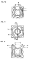
- Fig. 1 shows a first component 1 according to the invention in the form of a cube. This is, apart from corresponding connecting means, designed essentially as a hollow body. At each of its six sides is in each case a first connecting means 2, consisting of a circular bore 3 (see also the other FIGS. 2 to 5 ) With the embodiment shown a total of four chord-like inwardly projecting projections 4, which locally reduce the diameter of the bore 3 something.
- Fig. 4 which shows a sectional view through two of the four here by four offset by 90 ° to each other arranged latching projections 4.
- a 45 ° twisted sectional view is in Fig. 5 shown.
- the bore 3 is otherwise substantially cylindrical and is only constricted via the locking projections 4.
- the circular bore 3 is in a further cylindrical bore 5, which, depending on the configuration of a second component to be fixed, the leadership and Kippstabilmaschine is used after in the latter provided on the second component extension, adjacent to the bore inner wall, engages , which will be described below with respect to the FIGS. 19-21 will be received.
- Each hole 3 is surrounded by a mounting hole 6, which in turn is limited by a total of four rectangular or here square and funnel-shaped inclined inwardly extending wall sections 7, which are connected to each other via rounded corner sections 8.
- These wall sections 7 serve as abutment sections for a second component to be locked in, provided that the latter has correspondingly shaped wall sections. Over this the detent position is fixed. If the second component does not have such adjoining oblique wall sections, the upper side 9, which delimits the circular bore 3, serves as an abutment for the second component to be engaged, then optionally rotatably mounted.
- the respective funnel-shaped wall sections 7 merge on the outside into the respective side surfaces 11 of the respective cube sections, which in turn terminate in the respective cube edges 10.
- the side surfaces 11 serve as bearing surfaces for the corresponding side surfaces 11 of a second component fixed further first component 1, which will be discussed below.
- the first component 1 is a substantially open, hollow component, each of the circular bores 3 continues into the hollow interior, that is, between two opposite, offset by 180 ° to each other holes 3 a complete passage is given, see in particular the sectional views 4 and 5.
- Fig. 2 shows a second component 12 according to the invention, which is designed here as a connecting member 13 and has a plate-shaped base body 14, at its opposite flat sides, two second connecting means 15 are provided.
- Each connecting means 15 comprises an annular bead 16, which is integrally formed on a relatively short extension 17 extending from the respective surface of the main body 14.
- the extensions including ring bulbs are, see Fig. 9 , hollow overall.
- Each annular bead 16 increases the outer diameter of the projection 17 something and forms, as seen in the direction of the base body 14, quasi a locking portion, that is, it is designed here as a continuous locking ring, behind which in the transition to the base body 14 formed circumferential locking groove already latching portions 4 described in the first component lock, which will be discussed below.
- the plate-shaped main body itself here also square executed, that is, that its shape corresponds to the mounting hole 6 of the first component 1. He also has here arranged in a truncated pyramid inclined wall sections 18, which are connected to each other via rounded corner portions 19.
- the wall sections 18 form the support section with which the second component rests against the abutment section of the first component, formed by the funnel-shaped wall sections 7 of the mounting opening 6.
- FIGS. 10-13 show the two components 1 and 12 in their locked-together mounting position.
- the second component 12 is moved ahead with the annular bead 16 into the circular bore 3.
- the outer diameter of the annular bead 16 is slightly larger than the inner diameter of the circular bore 3, which is reduced via the latching projections 4, so that the annular bead abuts against the four symmetrically arranged latching projections 4. If the second component is now pressed firmly against the first, then there is an elastic deformation of the insertion bevels on its upper side having locking projections 4 and also having a slight chamfer annular bead 16. This is past the locking projections 4, until he, see the sectional view according to Fig. 12 , which engages behind latching projections.
- FIG. 14 and the sectional view according to Fig. 15 show, in a slightly twisted position, the wall portions 7 and 18 away from each other, and inevitably the annular bead 16 is pulled axially from the circular bore 3 and thus also from the latching engagement behind the locking projections 4.
- Fig. 16 shows, of course, given the opportunity to connect to the second connecting means 15 of the second component 12, a further first component 1, this is exemplary in Fig. 16 shown.
- first components 1 are gripped and rotated relative to each other about the longitudinal axis, the second component 12 will inevitably remain in one component 1, while it is rotated together with the first component relative to the other first component, so that it comes to separation.
- FIGS. 17 and 18 show an example of a possible structure, which consists of a total of four first components 1, which are connected to each other via corresponding connection components 12, wherein the eckigen component 1, a further second component 12 is inserted on the upper side. Obviously, the side surfaces 11 of two interconnected via a second component 12 first components 1 are flat to each other. The second component 12 is not visible in the assembly position, it is completely enclosed between the two components 1.
- FIGS. 17 and 18 shown structure is merely exemplary nature. It is of course possible to create a wide variety of geometries and structures from the components 1 and 12 shown. In addition, neither the geometry of the first component 1 nor that of the second component 12 is limited to the exemplary embodiments shown. Thus, it is possible to perform a first component 1, for example, as an elongated rectangle or as a plate or the like, such as a second component 12, for example, as a multi-surface component, for. B. in cube shape or pyramid shape or Rhombenkuboktaederform etc. may be performed, in which case second connecting means 15 are then provided on preferably all corresponding given pages. This makes it possible to construct any angle other than 90 ° angle.
- a second component if it is plate-shaped, does not have to have a second connection means 15 on both sides. It would also be conceivable, for example, to close assembly openings 6 of adjacent first components 1, to provide a second connection means 15 on only one side and to execute the other side in a planar manner, as of course such a second component may be designed as an elongate rail, of course.
- FIGS. 19-21 show now only by way of example a further embodiment of a first and a second component.
- the first component 1 is here in the form of a, seen from above, cruciform shaped component, for example in the form of a mounting base executed.
- first connecting means 2 are provided, each comprising a circular bore 3 with inwardly directed, chord-like latching projections 4, of which four per connecting means 2 are assumed to be provided here as well.
- the circular bore goes over in a smaller diameter cylindrical bore 5. That is, each connection means 2 corresponds to the connection means as set forth in the embodiment described above.
- the second component 12 is designed here as an elongated rod, at one end of a second connecting means 15 is formed, such may also be provided at the other end.
- the rod is now introduced with the second connecting means 15 ahead in the circular bore 2, with sufficient pressure it comes about that the locking projections 4 and the annular bead 16 whose outer diameter is greater than the distance between two opposing locking projections 4, are easily deformed, until the annular bead 16 engages behind the locking projections 4 and locked there.
- one or more support surfaces 20 are formed above the projection 17, which rest on the abutment surface forming peripheral edge surface 9, which surrounds the circular bore 3, in the latched mounting position, thus limiting the insertion movement.
- a downwardly projecting extension 21 for example in the form of a web cross 22.
- the web length is dimensioned so that the webs bear with their outer sides against the inner wall of the bore 5. This is on the one hand ensures a certain leadership when plugging, on the other hand, this flat system counteracts a tilting.
- the bore inner wall opposite the webs can overcome.
- the web cross 22 can of course also a hollow or fully cylindrical extension, which then rests with its outer surface over the entire surface of the bore inner wall, be provided, etc.
- a second component 12 is embodied here as a quadrangular frame 23, at the corners of each second connecting means 15 comprising the respective annular bead 16 are provided or formed, wherein the projection 17 of a slightly elevated, the mounting coding serving plate-shaped base body 14 extends.
- the second component 12 could also be designed as a plate.
- On several of these connecting means are exemplary first components 1 in the form of cubes, which in the manner already described with first connecting means comprising the circular bore 3 and the inwardly projecting locking projections 4, attached.
- first connecting means comprising the circular bore 3 and the inwardly projecting locking projections 4, attached.
- On one or both shown on the lower right corner first component cube is not shown here second component, as shown in the Fig. 6-9 is shown, plugged so that a third component cube can be attached.
- first cube-shaped component 1 which is connected to the lower left corner, second components 12 of different lengths, for example, are attached, as is the case with the first component 1 on the right-hand side.
- second component shown here as a quadrilateral frame as the first component on which first connecting means with the bore 3 and the latching projections 4 are provided instead of the second connecting means with the annular bead 16, into which then a second component, eg in the form of the connecting member after the Fig. 6-9 or in the form of the rod after the Fig. 19 - 21 is used, then in turn, a first component can be attached.
- first and second components are merely exemplary in nature. Rather, the components can have any shape, they can also represent concrete objects, especially if it is toy components in the first and second components.
- a component can be designed as a building component such as a wall, a roof section or the like, a component can equally well be embodied, for example, as a fence element, etc.
- the geometry selected has no limit, as long as the first and second components to be joined the connecting means according to the invention are provided in the concrete form.
- first and second components shown in the various embodiments can be arbitrarily combined with each other, ie that a first component in the form of a cube readily with a second component in the form of a rod or a fence component, etc. as well as a first component in the form of the mounting foot can be locked with a second component in the form of the double-sided connector element as a second component.
- the arbitrarily designed first and second components all have the connecting means according to the invention, which allow the arbitrary combinability.
- the embodiments are by no means limiting.
- FIGS. 24 and 25 a tool 24 with a handle 25, from which I extend an elongated shaft 26, at the lower end of an engagement pin 27 protrudes, which serves to release two latched components 1, 12.
- the engagement pin in the opening of in Fig. 25 shown second component 12 inserted. To release it is tilted, whereby the second component 12 is tilted and the annular bead 16 is released from the latching engagement under the latching projections 4.
Claims (16)
- Système de composants comprenant des premiers et deuxièmes composants (1, 12), en particulier des composants de jouet, étant entendu qu'aux fins de la jonction détachable d'un premier composant avec un deuxième composant, il est prévu sur le premier composant (1) un premier moyen de jonction (2) et sur le deuxième composant (12) un deuxième moyen de jonction (15), lesquels peuvent être enclenchés l'un avec l'autre, caractérisé en ce que le premier moyen de jonction (2) est un alésage circulaire du côté du composant (3) ayant au moins deux tenons d'enclenchement faisant saillie vers l'intérieur à la manière de tendons (4) et le deuxième moyen de jonction (15) un bourrelet annulaire (16) réalisé sur un tenon du côté du composant (17), et en ce qu'il est prévu sur le deuxième composant une section d'appui et sur le premier composant une section de butée, lesquelles prennent appui l'une sur l'autre dans la position de montage en limitant le mouvement d'insertion.
- Système de composants selon la revendication 1, caractérisé en ce qu'il est prévu deux ou trois ou quatre tenons d'enclenchement (4) agencés en décalage l'un par rapport à l'autre, respectivement, de 180° ou de 120° ou de 90°.
- Système de composants selon la revendication 1 ou 2, caractérisé en ce que le bourrelet annulaire (16) est réalisé comme bague d'enclenchement traversante.
- Système de composants selon la revendication 1 ou 2, caractérisé en ce que le bourrelet annulaire (16) est entaillé dans la direction radiale de façon à former des sections de bourrelet annulaire distinctes.
- Système de composants selon la revendication 1 ou 2, caractérisé en ce que les deux composants (1, 12) peuvent uniquement être enclenchés l'un avec l'autre dans une ou plusieurs positions identifiées, étant entendu que le bourrelet annulaire (16) est réalisé au moyen de sections de bourrelet annulaire distinctes dont la position est choisie en fonction de la position des sections d'enclenchement.
- Système de composants selon l'une des revendications précédentes, caractérisé en ce que le tenon (17) est réalisé dans un matériau plein ou creux.
- Système de composants selon l'une des revendications précédentes, caractérisé en ce que l'alésage circulaire (3) se prolonge par un alésage cylindrique concentrique supplémentaire (5) d'un diamètre inférieur et en ce qu'il est prévu à la suite du bourrelet annulaire (16) un appendice (21) qui s'engage dans l'alésage supplémentaire (5) et prend appui au moins au niveau d'une section sur la paroi intérieure de l'alésage.
- Système de composants selon la revendication 7, caractérisé en ce que l'appendice (21) est réalisé comme broche cylindrique pleine ou creuse ou comme tige allongée ou comme potence (22).
- Système de composants selon l'une des revendications précédentes, caractérisé en ce que l'alésage (3) du premier composant (1) est entouré par une ouverture de montage (6) rectangulaire, de préférence carrée, qui est délimitée par des sections de paroi (7) s'étendant en oblique vers l'intérieur à la manière d'une trémie, et en ce que la surface dont le tenon (17) du deuxième composant (12) supportant le bourrelet annulaire (16) est écarté est délimitée par le biais de sections de paroi (18) agencées dans une forme rectangulaire, de préférence carrée, à la manière d'une pyramide tronquée.
- Système de composants selon la revendication 9, caractérisé en ce que les sections de paroi (7, 18) respectives sont reliées les unes avec les autres par des sections de coin (8, 19) de préférence arrondies.
- Système de composants selon l'une des revendications précédentes, caractérisé en ce qu'un premier composant (1) présente deux ou plusieurs premiers moyens de jonction (2) agencés en décalage l'un avec l'autre.
- Système de composants selon la revendication 11, caractérisé en ce que le premier composant (1) est réalisé comme plaque anguleuse ou ronde, rectangle, cube, pyramide, tétraèdre, octaèdre, rhombododécaèdre, dodécaèdre, icosaèdre ou autre corps à plusieurs surfaces ou plusieurs angles et les moyens de jonction (2) sont prévus sur plusieurs, et de préférence tous les côtés.
- Système de composants selon l'une des revendications précédentes, caractérisé en ce que le deuxième composant (12) est un composant de jonction servant à relier deux premiers composants, qui présente deux ou plusieurs bourrelets annulaires (16) agencés en décalage l'un par rapport à l'autre.
- Système de composants selon la revendication 13, caractérisé en ce que les bourrelets annulaires (16) présents sur le deuxième composant (12) en forme de plaque, de barre ou de rectangle sont agencés sur des faces ou des extrémités du composant (12) situées en opposition ou en ce que les bourrelets annulaires (16) sont agencés sur plusieurs, et de préférence toutes les faces du deuxième composant (12) en forme de cube, de rectangle, de pyramide, de tétraèdre, d'octaèdre, de rhombododécaèdre, de dodécaèdre ou d'icosaèdre ou d'une autre forme à plusieurs surfaces ou plusieurs angles.
- Système de composants selon la revendication 14, caractérisé en ce que le deuxième composant (12) présente, dans la zone d'un tenon (17), un alésage pratiqué dans le composant (12) réalisé le cas échéant dans l'ensemble comme corps creux.
- Système de composants selon l'une des revendications précédentes, caractérisé en ce que les composants (1, 12) sont des composants de jouet en matière plastique.
Priority Applications (1)
| Application Number | Priority Date | Filing Date | Title |
|---|---|---|---|
| PL10169792T PL2283904T3 (pl) | 2009-08-13 | 2010-07-16 | System części konstrukcyjnych |
Applications Claiming Priority (1)
| Application Number | Priority Date | Filing Date | Title |
|---|---|---|---|
| DE102009037059A DE102009037059B4 (de) | 2009-08-13 | 2009-08-13 | Bauteilesystem |
Publications (2)
| Publication Number | Publication Date |
|---|---|
| EP2283904A1 EP2283904A1 (fr) | 2011-02-16 |
| EP2283904B1 true EP2283904B1 (fr) | 2014-06-11 |
Family
ID=43037848
Family Applications (1)
| Application Number | Title | Priority Date | Filing Date |
|---|---|---|---|
| EP10169792.8A Active EP2283904B1 (fr) | 2009-08-13 | 2010-07-16 | Système de composants |
Country Status (11)
| Country | Link |
|---|---|
| US (1) | US8801491B2 (fr) |
| EP (1) | EP2283904B1 (fr) |
| CN (1) | CN101991959B (fr) |
| AR (1) | AR077571A1 (fr) |
| BR (1) | BRPI1002309B1 (fr) |
| DE (1) | DE102009037059B4 (fr) |
| DK (1) | DK2283904T3 (fr) |
| ES (1) | ES2487532T3 (fr) |
| HK (1) | HK1152266A1 (fr) |
| PL (1) | PL2283904T3 (fr) |
| RU (1) | RU2459650C2 (fr) |
Families Citing this family (45)
| Publication number | Priority date | Publication date | Assignee | Title |
|---|---|---|---|---|
| CA2622153A1 (fr) * | 2005-09-22 | 2007-03-29 | Widee B.V. | Assemblage entre deux objets, objets destines a cet usage et systeme de construction modulaire |
| CN102302861A (zh) * | 2011-08-25 | 2012-01-04 | 珠海市鸿丰电子塑料玩具有限公司 | 一种可转动定位的连接装置 |
| WO2013080206A1 (fr) * | 2011-11-29 | 2013-06-06 | Wainztein Amitay | Jouet à unités de construction |
| ES2764841T3 (es) * | 2012-02-06 | 2020-06-04 | Artec Co Ltd | Bloque conectable |
| USD744599S1 (en) * | 2012-09-12 | 2015-12-01 | MerchSource, LLC | Construction toy set connector |
| KR101377026B1 (ko) * | 2012-10-23 | 2014-03-20 | (주)빅펌킨 | 조립식 완구 |
| NO337889B1 (no) * | 2013-11-28 | 2016-07-04 | Luna Loop As | Koblbart element for tildanning av lenker og romlige strukturer |
| US9308464B1 (en) * | 2014-02-20 | 2016-04-12 | Mattel, Inc. | Set of building components |
| USD748741S1 (en) * | 2014-02-25 | 2016-02-02 | Chiswick Innovations Ltd | Toy building block |
| USD762267S1 (en) | 2014-07-25 | 2016-07-26 | GoldieBlox, Inc. | Wheel hub |
| TWI517886B (zh) * | 2014-11-03 | 2016-01-21 | Genius Toy Taiwan Co Ltd | Clamped buckle groups and combinations thereof |
| US9839860B2 (en) * | 2015-05-12 | 2017-12-12 | Saturn Enterprises, Inc. | Interlocking construction toy |
| CN106693402A (zh) * | 2015-11-18 | 2017-05-24 | 施纯协 | 智慧积木掌中宝 |
| US9858827B2 (en) * | 2015-12-22 | 2018-01-02 | Courtney Shirvani | Caps and methods of usage |
| CN109310930B (zh) * | 2016-01-08 | 2021-08-03 | 乐聚发展有限公司 | 构件块和构件块组件 |
| RU2612919C1 (ru) * | 2016-01-25 | 2017-03-13 | Родионс Зеневичс | Игровой конструктор |
| USD812151S1 (en) * | 2016-01-26 | 2018-03-06 | Costas Sisamos | Snap-lock construction toy |
| CA3086982C (fr) * | 2016-03-24 | 2021-05-18 | Archi Enterprises Inc. | Systeme d'accessoires modulaire |
| CN106979193B (zh) * | 2017-03-31 | 2019-03-19 | 机器时代(北京)科技有限公司 | 扣件和拼接零件和扣件连接件和拼装组件和机器人 |
| ES2795043T3 (es) * | 2016-04-21 | 2020-11-20 | Jarola Vision B V | Elemento de acoplamiento |
| USD800845S1 (en) * | 2016-05-20 | 2017-10-24 | Gary Sprague | Block piece from toy set |
| PL3496834T3 (pl) | 2016-08-12 | 2023-11-06 | Trimiti Moebius Design Pty Ltd | Element konstrukcyjny do zabawy |
| US10617968B2 (en) * | 2016-08-24 | 2020-04-14 | Joshua Davis | Building blocks |
| WO2018060905A1 (fr) * | 2016-09-28 | 2018-04-05 | Frolic Limited | Blocs de construction et assemblages de blocs de construction |
| USD844715S1 (en) * | 2016-12-02 | 2019-04-02 | Jarola Vision B.V. | Construction element |
| USD912163S1 (en) * | 2016-12-02 | 2021-03-02 | Jarola Vision B.V. | Toy construction element |
| US10682580B2 (en) * | 2017-01-27 | 2020-06-16 | Traxart Toys LLC | Interactive construction toy system |
| CN106979506B (zh) * | 2017-04-27 | 2019-02-12 | 湖南粤港模科实业有限公司 | 一种模块化灯具支架及具有该支架的模块化灯具 |
| USD835728S1 (en) | 2017-08-28 | 2018-12-11 | MerchSource, LLC | Toy construction connector |
| US11697445B2 (en) | 2018-09-21 | 2023-07-11 | Arch Enterprises Inc. | Pulley assemblies for use in modular utility systems |
| US10343079B1 (en) * | 2017-12-22 | 2019-07-09 | Brian's Toys Inc. | Toy building brick system |
| USD892231S1 (en) * | 2018-02-23 | 2020-08-04 | Pacoware Inc. | Educational toy block |
| USD923717S1 (en) | 2018-04-13 | 2021-06-29 | Jarola Vision B.V. | Toy construction element |
| US10646791B2 (en) * | 2018-05-23 | 2020-05-12 | Brian's Toys Inc. | Toy building brick system |
| US11794124B2 (en) * | 2018-10-02 | 2023-10-24 | Snap Ships LLC | Connection systems for toy construction pieces, toy construction pieces including the same, and toy construction kits including the same |
| USD914108S1 (en) * | 2018-12-14 | 2021-03-23 | Building Blocks Learning Solutions Pvt. Ltd. | Robotic toy |
| USD914109S1 (en) * | 2018-12-14 | 2021-03-23 | Building Blocks Learning Solutions Pvt. Ltd. | Robotic toy |
| USD892230S1 (en) * | 2019-04-09 | 2020-08-04 | Ubtech Robotics Corp | Construction set block |
| JP6627037B1 (ja) * | 2019-07-26 | 2020-01-08 | みこと株式会社 | 組立玩具 |
| USD940795S1 (en) * | 2020-01-22 | 2022-01-11 | Costas Sisamos | Snap-lock construction toy beam unit |
| US20220062782A1 (en) * | 2020-08-26 | 2022-03-03 | KidKraft, Inc. | Connection device and system |
| CN112121371A (zh) * | 2020-09-21 | 2020-12-25 | 巢湖学院 | 一种学前教育用体育锻炼装置 |
| US11491415B2 (en) * | 2021-01-20 | 2022-11-08 | Lego A/S | Connector for constructions system and construction system |
| USD998056S1 (en) * | 2021-04-28 | 2023-09-05 | Xuejin He | Block |
| WO2023091051A1 (fr) * | 2021-11-19 | 2023-05-25 | Юрий Валентинович БЕДЕРОВ | Pièce de jeu de construction |
Citations (1)
| Publication number | Priority date | Publication date | Assignee | Title |
|---|---|---|---|---|
| WO1999016523A1 (fr) * | 1997-09-18 | 1999-04-08 | Lego A/S | Ensemble de jeu de construction |
Family Cites Families (15)
| Publication number | Priority date | Publication date | Assignee | Title |
|---|---|---|---|---|
| US3195266A (en) * | 1962-05-07 | 1965-07-20 | Richard A Onanian | Construction toy comprising blocks and coupling means |
| FR2274329A1 (fr) * | 1974-06-14 | 1976-01-09 | Monnet Jean | Jeu de construction a elements emboitables, procede et outillage pour sa fabrication |
| US4003144A (en) * | 1975-07-11 | 1977-01-18 | Damon Corporation | Educational block with replaceable chip |
| JPS5778Y2 (fr) * | 1979-03-09 | 1982-01-05 | ||
| US5306198A (en) * | 1993-05-24 | 1994-04-26 | Stanley Forman | Toy building block assembly |
| BE1010737A3 (fr) * | 1996-11-05 | 1998-12-01 | Meys Jean Michel Jacques Paul | Corps de construction. |
| NL1006524C2 (nl) * | 1997-07-10 | 1999-01-12 | Wild Design Holding Gmbh | Modulair bouwsysteem. |
| CN2320300Y (zh) * | 1997-12-09 | 1999-05-26 | 陈金益 | 导电型积木之装置 |
| JP4488588B2 (ja) * | 2000-05-29 | 2010-06-23 | 株式会社ニフコ | クリップ |
| CN2499093Y (zh) * | 2001-09-19 | 2002-07-10 | 少年玩具企业有限公司 | 积木 |
| US7175498B2 (en) * | 2001-11-29 | 2007-02-13 | Scott Garpow | Combination toy building block and container for holding liquids and the like |
| DE102004024395A1 (de) * | 2004-05-17 | 2005-12-08 | Bruder Spielwaren Gmbh & Co. Kg | Bausystem |
| WO2007020619A1 (fr) * | 2005-08-15 | 2007-02-22 | Boaz Leicht | Éléments de construction pouvant être reliés entre eux destinés à des jeux de défis intellectuels |
| US7736211B2 (en) * | 2005-11-29 | 2010-06-15 | Minds-I, Inc. | Construction system |
| EA008659B1 (ru) | 2006-08-10 | 2007-06-29 | Дмитрий Иванович ПАХОМОВ | Укупорочный колпачок для стандартного венчика горловины |
-
2009
- 2009-08-13 DE DE102009037059A patent/DE102009037059B4/de not_active Expired - Fee Related
-
2010
- 2010-07-06 BR BRPI1002309-7A patent/BRPI1002309B1/pt active IP Right Grant
- 2010-07-14 AR ARP100102553A patent/AR077571A1/es active IP Right Grant
- 2010-07-16 DK DK10169792.8T patent/DK2283904T3/da active
- 2010-07-16 ES ES10169792.8T patent/ES2487532T3/es active Active
- 2010-07-16 EP EP10169792.8A patent/EP2283904B1/fr active Active
- 2010-07-16 PL PL10169792T patent/PL2283904T3/pl unknown
- 2010-07-26 CN CN201010238012XA patent/CN101991959B/zh active Active
- 2010-08-05 RU RU2010132722/12A patent/RU2459650C2/ru active
- 2010-08-12 US US12/854,992 patent/US8801491B2/en active Active
-
2011
- 2011-06-21 HK HK11106353.5A patent/HK1152266A1/xx not_active IP Right Cessation
Patent Citations (1)
| Publication number | Priority date | Publication date | Assignee | Title |
|---|---|---|---|---|
| WO1999016523A1 (fr) * | 1997-09-18 | 1999-04-08 | Lego A/S | Ensemble de jeu de construction |
Also Published As
| Publication number | Publication date |
|---|---|
| CN101991959A (zh) | 2011-03-30 |
| BRPI1002309A2 (pt) | 2012-06-05 |
| DE102009037059B4 (de) | 2013-08-14 |
| BRPI1002309B1 (pt) | 2019-10-15 |
| EP2283904A1 (fr) | 2011-02-16 |
| ES2487532T3 (es) | 2014-08-21 |
| RU2010132722A (ru) | 2012-02-10 |
| PL2283904T3 (pl) | 2014-11-28 |
| AR077571A1 (es) | 2011-09-07 |
| US8801491B2 (en) | 2014-08-12 |
| HK1152266A1 (en) | 2012-02-24 |
| US20110039474A1 (en) | 2011-02-17 |
| DK2283904T3 (da) | 2014-08-11 |
| CN101991959B (zh) | 2013-06-05 |
| DE102009037059A1 (de) | 2011-02-17 |
| RU2459650C2 (ru) | 2012-08-27 |
Similar Documents
| Publication | Publication Date | Title |
|---|---|---|
| EP2283904B1 (fr) | Système de composants | |
| DE69922501T2 (de) | Vorrichtung zur wirbelsäulenosteosynthese mit klammer und verriegelung | |
| DE102006016858B4 (de) | Verbindungselement mit Gelenk für ein mehrteiliges Konstruktionsspielzeug | |
| EP3285897B1 (fr) | Éléments de jeu pouvant être assemblés à plat avec un corps creux ouvert d'un côté de type caisson et avec des saillies d'emboîtement disposées sur la face extérieure du fond ainsi qu'un dôme de fond disposé sur la face intérieure du fond | |
| EP0413012B1 (fr) | Dispositif de liaison liberable pour elements de jeux de construction | |
| EP0643911B1 (fr) | Cage démontable | |
| EP3221524B1 (fr) | Système modulaire | |
| EP3478975B1 (fr) | Clip doté d'une tête et d'une tige s'étendant le long d'un axe longitudinal à partir de la tête | |
| WO2010102735A1 (fr) | Panneau | |
| DE202008007378U1 (de) | Schraubclip | |
| DE202014101497U1 (de) | Handwerkzeug mit Griff | |
| WO2005066434A1 (fr) | Systeme de coffrage | |
| EP0307628B2 (fr) | Structure réticulée avec barres et noeuds | |
| WO2019145436A1 (fr) | Système de construction | |
| DE102018101944A1 (de) | Unlösbare Befestigungsvorrichtung | |
| EP1927766B1 (fr) | Douille perforée | |
| EP2615223B1 (fr) | Dispositif de recouvrement de bords de revêtements | |
| DE19500716A1 (de) | Verbindungselement für rohrförmige Gegenstände | |
| DE3001195A1 (de) | Schnappvorrichtung zur loesbaren verbindung von zwei teilen oder brettern | |
| BE1020602A3 (de) | Hohlwanddose aus kunststoff. | |
| DE2338936A1 (de) | Scharnierartig zusammenfuegbares bauspielzeug | |
| EP2662578B1 (fr) | Cheville plate et liaison en utilisant une cheville plate | |
| DE102020129761A1 (de) | Verbindungselement für Plattenelemente | |
| WO2005049164A1 (fr) | Figurine-jouet | |
| DE102011012954B4 (de) | Verbindungselement und Baukastensystem |
Legal Events
| Date | Code | Title | Description |
|---|---|---|---|
| PUAI | Public reference made under article 153(3) epc to a published international application that has entered the european phase |
Free format text: ORIGINAL CODE: 0009012 |
|
| AK | Designated contracting states |
Kind code of ref document: A1 Designated state(s): AL AT BE BG CH CY CZ DE DK EE ES FI FR GB GR HR HU IE IS IT LI LT LU LV MC MK MT NL NO PL PT RO SE SI SK SM TR |
|
| AX | Request for extension of the european patent |
Extension state: BA ME RS |
|
| 17P | Request for examination filed |
Effective date: 20110720 |
|
| RIC1 | Information provided on ipc code assigned before grant |
Ipc: A63H 33/10 20060101AFI20121217BHEP |
|
| 17Q | First examination report despatched |
Effective date: 20130213 |
|
| GRAP | Despatch of communication of intention to grant a patent |
Free format text: ORIGINAL CODE: EPIDOSNIGR1 |
|
| INTG | Intention to grant announced |
Effective date: 20140108 |
|
| GRAP | Despatch of communication of intention to grant a patent |
Free format text: ORIGINAL CODE: EPIDOSNIGR1 |
|
| GRAS | Grant fee paid |
Free format text: ORIGINAL CODE: EPIDOSNIGR3 |
|
| GRAA | (expected) grant |
Free format text: ORIGINAL CODE: 0009210 |
|
| INTG | Intention to grant announced |
Effective date: 20140416 |
|
| AK | Designated contracting states |
Kind code of ref document: B1 Designated state(s): AL AT BE BG CH CY CZ DE DK EE ES FI FR GB GR HR HU IE IS IT LI LT LU LV MC MK MT NL NO PL PT RO SE SI SK SM TR |
|
| REG | Reference to a national code |
Ref country code: GB Ref legal event code: FG4D Free format text: NOT ENGLISH |
|
| REG | Reference to a national code |
Ref country code: CH Ref legal event code: EP |
|
| REG | Reference to a national code |
Ref country code: IE Ref legal event code: FG4D Free format text: LANGUAGE OF EP DOCUMENT: GERMAN |
|
| REG | Reference to a national code |
Ref country code: AT Ref legal event code: REF Ref document number: 671949 Country of ref document: AT Kind code of ref document: T Effective date: 20140715 |
|
| REG | Reference to a national code |
Ref country code: DE Ref legal event code: R096 Ref document number: 502010007172 Country of ref document: DE Effective date: 20140724 |
|
| REG | Reference to a national code |
Ref country code: DK Ref legal event code: T3 Effective date: 20140805 |
|
| REG | Reference to a national code |
Ref country code: ES Ref legal event code: FG2A Ref document number: 2487532 Country of ref document: ES Kind code of ref document: T3 Effective date: 20140821 |
|
| REG | Reference to a national code |
Ref country code: NL Ref legal event code: T3 |
|
| PG25 | Lapsed in a contracting state [announced via postgrant information from national office to epo] |
Ref country code: FI Free format text: LAPSE BECAUSE OF FAILURE TO SUBMIT A TRANSLATION OF THE DESCRIPTION OR TO PAY THE FEE WITHIN THE PRESCRIBED TIME-LIMIT Effective date: 20140611 Ref country code: GR Free format text: LAPSE BECAUSE OF FAILURE TO SUBMIT A TRANSLATION OF THE DESCRIPTION OR TO PAY THE FEE WITHIN THE PRESCRIBED TIME-LIMIT Effective date: 20140912 Ref country code: NO Free format text: LAPSE BECAUSE OF FAILURE TO SUBMIT A TRANSLATION OF THE DESCRIPTION OR TO PAY THE FEE WITHIN THE PRESCRIBED TIME-LIMIT Effective date: 20140911 Ref country code: LT Free format text: LAPSE BECAUSE OF FAILURE TO SUBMIT A TRANSLATION OF THE DESCRIPTION OR TO PAY THE FEE WITHIN THE PRESCRIBED TIME-LIMIT Effective date: 20140611 |
|
| REG | Reference to a national code |
Ref country code: LT Ref legal event code: MG4D |
|
| PG25 | Lapsed in a contracting state [announced via postgrant information from national office to epo] |
Ref country code: HR Free format text: LAPSE BECAUSE OF FAILURE TO SUBMIT A TRANSLATION OF THE DESCRIPTION OR TO PAY THE FEE WITHIN THE PRESCRIBED TIME-LIMIT Effective date: 20140611 Ref country code: LV Free format text: LAPSE BECAUSE OF FAILURE TO SUBMIT A TRANSLATION OF THE DESCRIPTION OR TO PAY THE FEE WITHIN THE PRESCRIBED TIME-LIMIT Effective date: 20140611 Ref country code: SE Free format text: LAPSE BECAUSE OF FAILURE TO SUBMIT A TRANSLATION OF THE DESCRIPTION OR TO PAY THE FEE WITHIN THE PRESCRIBED TIME-LIMIT Effective date: 20140611 |
|
| REG | Reference to a national code |
Ref country code: PL Ref legal event code: T3 Ref country code: HU Ref legal event code: AG4A Ref document number: E020878 Country of ref document: HU |
|
| PG25 | Lapsed in a contracting state [announced via postgrant information from national office to epo] |
Ref country code: SK Free format text: LAPSE BECAUSE OF FAILURE TO SUBMIT A TRANSLATION OF THE DESCRIPTION OR TO PAY THE FEE WITHIN THE PRESCRIBED TIME-LIMIT Effective date: 20140611 Ref country code: EE Free format text: LAPSE BECAUSE OF FAILURE TO SUBMIT A TRANSLATION OF THE DESCRIPTION OR TO PAY THE FEE WITHIN THE PRESCRIBED TIME-LIMIT Effective date: 20140611 Ref country code: RO Free format text: LAPSE BECAUSE OF FAILURE TO SUBMIT A TRANSLATION OF THE DESCRIPTION OR TO PAY THE FEE WITHIN THE PRESCRIBED TIME-LIMIT Effective date: 20140611 Ref country code: PT Free format text: LAPSE BECAUSE OF FAILURE TO SUBMIT A TRANSLATION OF THE DESCRIPTION OR TO PAY THE FEE WITHIN THE PRESCRIBED TIME-LIMIT Effective date: 20141013 |
|
| PG25 | Lapsed in a contracting state [announced via postgrant information from national office to epo] |
Ref country code: IS Free format text: LAPSE BECAUSE OF FAILURE TO SUBMIT A TRANSLATION OF THE DESCRIPTION OR TO PAY THE FEE WITHIN THE PRESCRIBED TIME-LIMIT Effective date: 20141011 |
|
| REG | Reference to a national code |
Ref country code: CH Ref legal event code: PL |
|
| REG | Reference to a national code |
Ref country code: DE Ref legal event code: R097 Ref document number: 502010007172 Country of ref document: DE |
|
| PG25 | Lapsed in a contracting state [announced via postgrant information from national office to epo] |
Ref country code: MC Free format text: LAPSE BECAUSE OF FAILURE TO SUBMIT A TRANSLATION OF THE DESCRIPTION OR TO PAY THE FEE WITHIN THE PRESCRIBED TIME-LIMIT Effective date: 20140611 |
|
| PLBE | No opposition filed within time limit |
Free format text: ORIGINAL CODE: 0009261 |
|
| STAA | Information on the status of an ep patent application or granted ep patent |
Free format text: STATUS: NO OPPOSITION FILED WITHIN TIME LIMIT |
|
| REG | Reference to a national code |
Ref country code: IE Ref legal event code: MM4A |
|
| PG25 | Lapsed in a contracting state [announced via postgrant information from national office to epo] |
Ref country code: CH Free format text: LAPSE BECAUSE OF NON-PAYMENT OF DUE FEES Effective date: 20140731 Ref country code: LI Free format text: LAPSE BECAUSE OF NON-PAYMENT OF DUE FEES Effective date: 20140731 |
|
| 26N | No opposition filed |
Effective date: 20150312 |
|
| REG | Reference to a national code |
Ref country code: DE Ref legal event code: R097 Ref document number: 502010007172 Country of ref document: DE Effective date: 20150312 |
|
| REG | Reference to a national code |
Ref country code: FR Ref legal event code: PLFP Year of fee payment: 6 |
|
| PG25 | Lapsed in a contracting state [announced via postgrant information from national office to epo] |
Ref country code: SI Free format text: LAPSE BECAUSE OF FAILURE TO SUBMIT A TRANSLATION OF THE DESCRIPTION OR TO PAY THE FEE WITHIN THE PRESCRIBED TIME-LIMIT Effective date: 20140611 |
|
| PG25 | Lapsed in a contracting state [announced via postgrant information from national office to epo] |
Ref country code: IE Free format text: LAPSE BECAUSE OF NON-PAYMENT OF DUE FEES Effective date: 20140716 |
|
| PG25 | Lapsed in a contracting state [announced via postgrant information from national office to epo] |
Ref country code: SM Free format text: LAPSE BECAUSE OF FAILURE TO SUBMIT A TRANSLATION OF THE DESCRIPTION OR TO PAY THE FEE WITHIN THE PRESCRIBED TIME-LIMIT Effective date: 20140611 |
|
| PG25 | Lapsed in a contracting state [announced via postgrant information from national office to epo] |
Ref country code: MT Free format text: LAPSE BECAUSE OF FAILURE TO SUBMIT A TRANSLATION OF THE DESCRIPTION OR TO PAY THE FEE WITHIN THE PRESCRIBED TIME-LIMIT Effective date: 20140611 Ref country code: BG Free format text: LAPSE BECAUSE OF FAILURE TO SUBMIT A TRANSLATION OF THE DESCRIPTION OR TO PAY THE FEE WITHIN THE PRESCRIBED TIME-LIMIT Effective date: 20140611 Ref country code: CY Free format text: LAPSE BECAUSE OF FAILURE TO SUBMIT A TRANSLATION OF THE DESCRIPTION OR TO PAY THE FEE WITHIN THE PRESCRIBED TIME-LIMIT Effective date: 20140611 |
|
| REG | Reference to a national code |
Ref country code: FR Ref legal event code: PLFP Year of fee payment: 7 |
|
| PG25 | Lapsed in a contracting state [announced via postgrant information from national office to epo] |
Ref country code: LU Free format text: LAPSE BECAUSE OF NON-PAYMENT OF DUE FEES Effective date: 20140716 |
|
| REG | Reference to a national code |
Ref country code: AT Ref legal event code: MM01 Ref document number: 671949 Country of ref document: AT Kind code of ref document: T Effective date: 20150716 |
|
| PG25 | Lapsed in a contracting state [announced via postgrant information from national office to epo] |
Ref country code: AT Free format text: LAPSE BECAUSE OF NON-PAYMENT OF DUE FEES Effective date: 20150716 |
|
| REG | Reference to a national code |
Ref country code: FR Ref legal event code: PLFP Year of fee payment: 8 |
|
| PG25 | Lapsed in a contracting state [announced via postgrant information from national office to epo] |
Ref country code: MK Free format text: LAPSE BECAUSE OF FAILURE TO SUBMIT A TRANSLATION OF THE DESCRIPTION OR TO PAY THE FEE WITHIN THE PRESCRIBED TIME-LIMIT Effective date: 20140611 |
|
| REG | Reference to a national code |
Ref country code: FR Ref legal event code: PLFP Year of fee payment: 9 |
|
| PG25 | Lapsed in a contracting state [announced via postgrant information from national office to epo] |
Ref country code: AL Free format text: LAPSE BECAUSE OF FAILURE TO SUBMIT A TRANSLATION OF THE DESCRIPTION OR TO PAY THE FEE WITHIN THE PRESCRIBED TIME-LIMIT Effective date: 20140611 |
|
| P01 | Opt-out of the competence of the unified patent court (upc) registered |
Effective date: 20230424 |
|
| PGFP | Annual fee paid to national office [announced via postgrant information from national office to epo] |
Ref country code: NL Payment date: 20230720 Year of fee payment: 14 |
|
| PGFP | Annual fee paid to national office [announced via postgrant information from national office to epo] |
Ref country code: TR Payment date: 20230713 Year of fee payment: 14 Ref country code: IT Payment date: 20230731 Year of fee payment: 14 Ref country code: GB Payment date: 20230724 Year of fee payment: 14 Ref country code: ES Payment date: 20230821 Year of fee payment: 14 Ref country code: CZ Payment date: 20230707 Year of fee payment: 14 |
|
| PGFP | Annual fee paid to national office [announced via postgrant information from national office to epo] |
Ref country code: PL Payment date: 20230703 Year of fee payment: 14 Ref country code: HU Payment date: 20230710 Year of fee payment: 14 Ref country code: FR Payment date: 20230724 Year of fee payment: 14 Ref country code: DK Payment date: 20230724 Year of fee payment: 14 Ref country code: DE Payment date: 20230713 Year of fee payment: 14 Ref country code: BE Payment date: 20230719 Year of fee payment: 14 |