EP2282425A1 - Kommunikationsvorrichtung und Kommunikationsverfahren - Google Patents
Kommunikationsvorrichtung und Kommunikationsverfahren Download PDFInfo
- Publication number
- EP2282425A1 EP2282425A1 EP10169881A EP10169881A EP2282425A1 EP 2282425 A1 EP2282425 A1 EP 2282425A1 EP 10169881 A EP10169881 A EP 10169881A EP 10169881 A EP10169881 A EP 10169881A EP 2282425 A1 EP2282425 A1 EP 2282425A1
- Authority
- EP
- European Patent Office
- Prior art keywords
- communication module
- transmission
- output
- signal
- level
- Prior art date
- Legal status (The legal status is an assumption and is not a legal conclusion. Google has not performed a legal analysis and makes no representation as to the accuracy of the status listed.)
- Withdrawn
Links
- 238000004891 communication Methods 0.000 title claims abstract description 298
- 238000000034 method Methods 0.000 title claims description 22
- 230000005540 biological transmission Effects 0.000 claims abstract description 250
- 230000005684 electric field Effects 0.000 claims abstract description 83
- 230000008054 signal transmission Effects 0.000 claims abstract description 22
- 230000007613 environmental effect Effects 0.000 description 36
- 230000008569 process Effects 0.000 description 12
- 230000008878 coupling Effects 0.000 description 9
- 238000010168 coupling process Methods 0.000 description 9
- 238000005859 coupling reaction Methods 0.000 description 9
- 238000010586 diagram Methods 0.000 description 7
- 230000006870 function Effects 0.000 description 6
- 230000006872 improvement Effects 0.000 description 6
- 238000005259 measurement Methods 0.000 description 3
- 238000001514 detection method Methods 0.000 description 2
- 238000012986 modification Methods 0.000 description 2
- 230000004048 modification Effects 0.000 description 2
- 230000002093 peripheral effect Effects 0.000 description 2
- 210000004243 sweat Anatomy 0.000 description 2
- 230000009471 action Effects 0.000 description 1
- 230000004075 alteration Effects 0.000 description 1
- 230000008859 change Effects 0.000 description 1
- 238000013461 design Methods 0.000 description 1
- 230000001105 regulatory effect Effects 0.000 description 1
Images


Classifications
-
- H—ELECTRICITY
- H04—ELECTRIC COMMUNICATION TECHNIQUE
- H04B—TRANSMISSION
- H04B13/00—Transmission systems characterised by the medium used for transmission, not provided for in groups H04B3/00 - H04B11/00
- H04B13/005—Transmission systems in which the medium consists of the human body
Definitions
- the present invention contains subject matter related to Japanese Patent Application JP 2009-171084 filed in the Japanese Patent Office on July 22, 2009, the entire contents of which being incorporated herein by reference.
- the present invention relates to a communication device and a communication method which perform communication using electric field coupling.
- RFID Radio Frequency IDentification
- infrared communication and short-range radio communication schemes besides wired communication for a system having a communication device are known. Since non-contact communication by radio waves or the like is possible, the non-contact communication is utilized in various places, for example, such as an event site and a station ticket gate.
- the communication scheme uses the above-described electric field coupling, the communication performance thereof is affected by environmental noise (external noise generated by a peripheral device, noise of a power supply system, or the like).
- environmental noise external noise generated by a peripheral device, noise of a power supply system, or the like.
- a noise level is high, a transmission signal may be buried in the environmental noise. Therefore, there is a problem in that communication performance may be degraded.
- an output level of the transmission signal may be set to be higher than the noise level.
- the output level is set to be high, there is a problem in that a radiated electric field becomes excessively strong and communication is performed even though it is not immediately before a human body is in contact with a receiver, or a transmitter and a receiver directly communicate beyond the human body, thereby establishing communication without passing through the human body in spite of the human body being used for a signal transmission path.
- the transmitter is a portable device which is driven by a battery
- the battery life is shortened when the output level of the transmission signal is set to be simply high.
- the human body itself is affected by environmental noise. This is because the human body itself which is the signal transmission path functions as an antenna and easily picks up the environmental noise.
- the improvement of true communication performance may not be achieved even though it is possible to set an output level of a transmission signal on the basis of a noise level.
- a communication device for communicating with an external device using a human body as a signal transmission path, including: an electric field strength measuring unit configured to measure a noise level from a detected received electric field strength at the time of no signal after the received electric field strength is detected by the communication device when a transmission signal to be output to the external device is absent; a transmission output determination unit configured to determine an output level of the transmission signal to be transmitted to the external device on the basis of the measured noise level; and an output execution unit configured to output a transmission signal of the determined output level to the external device.
- the communication device includes the electric field strength measuring unit, the transmission output determination unit, and the output execution unit.
- the electric field strength measuring unit measures a noise level from the detected received electric field strength at the time of no signal, and outputs the measurement result to the transmission output determination unit.
- the transmission output determination unit determines an output level of the transmission signal to be transmitted to the external device on the basis of the measured noise level, and outputs the determination result to the output execution unit.
- the output execution unit outputs a transmission signal of the determined output level to the external device.
- environmental noise received by the human body itself may be specified in a state in which a transmission signal from the communication device to the external device is absent as described above, it is possible to recognize the environmental noise received by the human body itself when a noise level is measured on the basis of a state in which the transmission signal is absent. Consequently, it is possible to determine the output level of the transmission signal directed to the external device by considering the noise level. As a result, it contributes to the improvement of true communication performance in communication using the human body for the signal transmission path.
- the received electric field strength at the time of no signal may be a received electric field strength at the moment when the human body is in contact with the external device in a state in which the transmission signal directed to the external device is not started up.
- the human body itself functions as an antenna which picks up environmental noise in communication using the human body for the signal transmission path as described above.
- the noise level is particularly increased.
- the transmission output determination unit may determine a high output level when the measured noise level is high, and may determine a low output level when the measured noise level is low.
- the transmission output determination unit determines the output level of the transmission signal directed to the external device by following the measured noise level, thereby setting the output level of the transmission signal to an optimum magnitude commensurate with the noise level. Consequently, the transmission signal directed to the external device is not buried in the environmental noise, and also it is possible to prevent communication which does not pass through the human body as the signal transmission path.
- the output execution unit may output the transmission signal including information of the measured noise level or the determined output level to the external device.
- the output execution unit of the communication device outputs the transmission signal to the external device, but also the transmission signal includes information of the measured noise level or the determined output level. Consequently, for example, the communication device may also use the information for a subsequent determination of the output level or the like, and the external device may also use the information for adjustment or the like upon reception/transmission.
- the external device may be a communication module mounted on the human body, and the mounted communication module may include: a transmission output determination unit configured to determine an output level of a transmission signal to be returned to the communication device on the basis of the information of the measured noise level or the determined output level; and an output execution unit configured to output a transmission signal of the determined output level to the communication device.
- two-way communication is performed between the communication device and the communication module mounted on the human body.
- the communication module mounted on the human body also includes the transmission output determination unit and the output execution unit, but the transmission output determination unit determines the output level of the transmission signal to be returned to the communication device using the information of the noise level measured by the communication device or the output level determined thereby. Accordingly, since it is not necessary to measure the noise level in the mounted communication module, it is possible to simplify the configuration or control thereof.
- the communication module mounted on the human body may be started using the transmission signal from the communication device as a trigger, so that power consumption may be reduced.
- the transmission output determination unit may determine a high output level when the measured noise level or the determined output level is high, and may determine a low output level when the measured noise level or the determined output level is low.
- the transmission output determination unit determines the output level of the transmission signal directed to the communication device by following the measured noise level or the determined output level, it is possible to set the output level of the transmission signal to an optimum magnitude commensurate with the noise level. Consequently, even in two-way communication, the transmission signal directed to the communication device is not buried in the environmental noise, and it is possible to prevent communication which does not pass through the human body as the signal transmission path.
- a received electric field strength of a transmission signal returned from the external device may be further detected, the electric field strength measuring unit may measure a received signal level from the detected received electric field strength of the transmission signal, and the transmission output determination unit may re-determine an output level of a transmission signal to be transmitted to the external device on the basis of the measured received signal and a noise level before or after the received signal is detected.
- the electric field strength measuring unit of the communication device in two-way communication of the communication device and the external device, not only measures the noise level from the received electric field strength at the time of no signal, but also measures the received signal level by the received electric field strength of the transmission signal returned from the external device.
- the transmission output determination unit re-determines the output level of the transmission signal to be transmitted to the external device on the basis of the former noise level and the latter received signal level.
- a high output level is necessary in initial communication when it is possible to re-adjust the output level of the transmission signal directed to the external device by considering an actual communication state as described above.
- a low output level is adequate thereafter, it is possible to avoid transmission by a useless output level and it is possible to reduce power consumption while improving true communication performance.
- An eighth embodiment of the invention is a communication method for communication between a first communication module and a second communication module using a human body as a signal transmission path.
- the communication method includes the steps of: detecting, by the first communication module, a received electric field strength at the time of no signal as the moment when the human body is in contact with the second communication module in a state in which a transmission signal is not started up when the transmission signal is output to the second communication module; measuring, by the first communication module, a noise level from the detected received electric field strength at the time of no signal; following, by the first communication module, a high/low state of the measured noise level and determining an output level of a transmission signal to be transmitted to the second communication module; outputting, by the first communication module, a transmission signal of the determined output level to the second communication module along with information of the measured noise level or the determined output level; following, by the second communication module, a high/low state of the information of the measured noise level or the determined output level and determining an output level of a transmission signal to be returned to the first communication module; and outputting, by the second communication module, a transmission signal of the determined output level to the first communication module.
- the human body itself also has a function as an antenna which picks up environmental noise in communication using the human body for the signal transmission path.
- the noise level is particularly increased.
- the communication performance of communication using the human body as the signal transmission path is significantly improved.
- the first communication module determines the output level of the transmission signal directed to the second communication module by following the measured noise level, it is possible to set the output level of the transmission signal to an optimum magnitude commensurate with the noise level. Consequently, the transmission signal from the first communication module to the second communication module is not buried in the environmental noise, and it is possible to prevent communication which does not pass through the human body as the signal transmission path.
- the first communication module also provides the second communication module with information of the measured noise level or the determined output level. Since the second communication module determines an output level of the transmission signal to be returned to the first communication module using the level information, it is not necessary to measure the noise level in the second communication module and it is possible to simplify the configuration or control thereof.
- the second communication module may be started using the transmission signal from the first communication module as a trigger, thereby reducing power consumption.
- the second communication module determines an output level of the transmission signal directed to the first communication module by following the above-described level information, it is also possible to set the output level of the transmission signal to an optimum magnitude commensurate with the noise level.
- the transmission signal from the second communication module to the first communication module is also not buried in the environmental noise, and it is possible to prevent communication which does not pass through the human body as the signal transmission path.
- a communication device and a communication method capable of recognizing environmental noise received by a human body since a noise level is computed in a state in which a transmission signal from a communication device is absent, and accomplishing the improvement of true communication performance.
- a communication system 1 of an embodiment shown in Fig. 1 is constructed between a door 74 of a building and an employee ID card 82 attached to a human body 80.
- This building internally has a plurality of rooms and the rooms neighboring each other are divided by a wall 72.
- the door 74 of this embodiment is rotatably supported on the wall 72 via a hinge, thereby opening/closing a part of the wall 72.
- a rotatably supported door knob 76 is provided in an appropriate position of the front side of the door 74. As shown in Fig. 1 , the knob 76 extends in a substantially horizontal direction along the front side of the door 74 in a state in which the door 74 is closed.
- the motion of the door knob 76 interlocks with a latch bolt provided on an end face of the door 74.
- the tip end of the latch bolt recedes to be substantially flush with the end face of the door 74.
- the knob 76 returns to a position shown in Fig. 1 by the urging force of a spring. Since the latch bolt is projected from the end face of the door 74, it is possible to temporarily tighten the door 74.
- a dead bolt is provided in the vicinity of the latch bolt.
- the dead bolt has a main tightening function of the door 74.
- the dead bolt In a state in which the door 74 is locked, the dead bolt is projected from the end face of the door 74, and is solidly engaged to the wall 72.
- the tip end of the dead bolt is substantially flush with the end face of the door 74 when the door 74 is unlocked, the main tightening of the door 74 is loosened and a temporarily tightened state is formed by the above-described latch bolt.
- the door 74 is locked or unlocked by communication using electric field coupling.
- a first communication module (communication device) 10 is embedded in the vicinity of the door knob 76 on an inner side of the door 74, and a second communication module (external device) 40 which is driven by a battery is provided on an employee ID card 82 suspended from the neck of the human body 80.
- the first communication module 10 authenticates a unique ID (identification signal) of the second communication module 40, and locks or unlocks the door 74.
- the first communication module 10 is a transceiver, and includes a transmission/reception electrode 12 for human body communication and a GND electrode 24 as shown in Fig. 2 .
- the transmission/reception electrode 12 is arranged in the vicinity of the surface of the door knob 76 which is capable of contacting the hand of the human body 80.
- the GND electrode is the GND of a circuit board and a GND portion extended from the GND of the circuit board.
- the GND electrode 24 is arranged in an appropriate position on a far side from the human body 80 by interposing the transmission/reception electrode 12.
- the transmission/reception electrode 12 is electrically connected to a control unit 14.
- the control unit 14 includes a transmission circuit 16 and a reception circuit 28.
- the transmission circuit 16 outputs a transmission signal to the transmission/reception electrode 12 in a fixed interrupt cycle, and drives the transmission/reception electrode 12 by generating a potential signal at the time.
- a reception signal from the transmission/reception electrode 12 is input to the reception circuit 28 in a fixed interrupt cycle.
- the transmission signal and the reception signal are alternately generated.
- the reception circuit RX is started up.
- the reception circuit RX is shut down.
- the reception circuit RX is started up in an interval (when no transmission signal is present) between the start-up transmission circuit TX and the next start-up transmission circuit TX.
- the transmission/reception electrode 12 detects a received electric field strength in the above-described interval, and outputs the detection result to the reception circuit 28.
- a received electric field strength of this embodiment and a noise level of environmental noise received by the human body 80 are in a substantially proportional relationship.
- a voltage value of a received electric field strength RSSI Receiveived Signal Strength Indication
- a level of a signal input to the first communication module 10 is taken on the horizontal axis
- the level of the signal input to the communication module 10 also becomes high as the received electric field strength becomes high.
- the received electric field strength detected by the communication module 10 corresponds to the noise level of environmental noise received by the human body 80.
- a communication distance by this embodiment is a short distance corresponding to PAN (Personal Area Network) or BAN (Body Area Network), and the communication modules 10 and 40 are in substantially the same environment. That is, the noise level received by the communication module 10 is substantially the same as the noise level received by the second communication module 40.
- PAN Personal Area Network
- BAN Body Area Network
- a value of the received electric field strength of this embodiment is detected by the transmission/reception electrode 12 at the moment when the hand of the human body 80 is in contact with the door knob 76, and is output to an electric field strength measuring unit 32.
- the moment when the hand is in contact with the door knob 76 not only corresponds to a point in time when the hand of the human body 80 is actually in contact with the door knob 76, but also corresponds to a point in time immediately before the hand is in contact with the door knob 76.
- the electric field strength measuring unit 32 is able to constantly measure a noise level of common environmental noise between the communication modules 10 and 40, but a noise level of environmental noise to be particularly measured becomes a particularly high noise level in environmental noise picked up by the human body 80.
- the transmission circuit 16 of this embodiment has a transmission output determination unit 18 or an output execution unit 20.
- the transmission output determination unit 18 determines an output level of a transmission signal on the basis of a noise level measured by the electric field strength measuring unit 32.
- the output execution unit 20 outputs a transmission signal of the determined output level to the second communication module 40.
- the output execution unit 20 also outputs information (for example, an index of level 4 or the like ) of the noise level measured by the electric field strength measuring unit 32 or the output level determined by the transmission output determination unit 18 to the second communication module 40.
- information for example, an index of level 4 or the like
- the first communication module 10 further includes a memory 22.
- the memory 22 stores a unique ID of the module 10.
- the second communication module 40 is also a transceiver, and includes a transmission/reception electrode 42 for human body communication and a GND electrode 54 as shown in Fig. 3 .
- the transmission/reception electrode 42 is arranged on the backside of the employee ID card 82 facing clothing of the human body 80.
- the GND electrode 54 is arranged in an appropriate position of the surface of the employee ID card 82 to which a photo or the like is attached.
- the transmission/reception electrode 42 is electrically connected to a control unit 44.
- the control unit 44 includes a transmission circuit 46 and a reception circuit 58.
- a received signal from the transmission/reception electrode 42 is input to the reception circuit 58 in a fixed interrupt cycle.
- the transmission circuit 46 outputs a transmission signal to the transmission/reception electrode 42 in a fixed interrupt cycle, and drives the transmission/reception electrode 42 by generating a potential signal at the time.
- the received signal of this embodiment is a signal obtained by demodulating the unique ID of the first communication module 10 and the information of the noise level of the environmental noise picked up by the human body 80 and measured by the electric field strength measuring unit 32 or the output level after the determination by the transmission output determination unit 18.
- the transmission level 46 also includes a transmission output determination unit 48 and an output execution unit 50.
- the transmission output determination unit 48 uses the information of the noise level of the environmental noise picked up by the human body 80 and measured by the electric field strength measuring unit 32 or the output level after the determination by the transmission output determination unit 18. In detail, the transmission output determination unit 48 determines an output level of a transmission signal to be returned to the communication module 10 on the basis of the measured noise level or the determined output level.
- the output execution unit 50 outputs a transmission signal of the determined output level to the first communication module 10.
- the second communication module 40 also includes a memory 52.
- the memory 52 stores a unique ID of the module 40.
- the control unit 14 of the first communication module 10 When the control unit 14 of the first communication module 10 has determined that the ID is normal, the second communication module 40 is specified and the door 74 is unlocked.
- FIG. 6 and 7 an operation flowchart of communication in which the human body 80 is set as a signal transmission path by the first communication module 10 and the second communication module 40 is shown.
- the operation according to an embodiment of the present invention of the above-described communication system 1 will be described.
- step S601 of Fig. 6 is when no transmission signal is present in the first communication module 10, that is, a reception state in which the reception circuit RX is started up to detect a signal.
- the transmission/reception electrode 12 detects a received electric field strength at the moment when the hand of the human body 80 is in contact with the door knob 76. Then, the process proceeds to step S602.
- step S602 the electric field strength measuring unit 32 measures a noise level of environmental noise picked up by the human body 80 from the received electric field strength of the above-described moment, and outputs the measurement result to the transmission output determination unit 18. Then, the process proceeds to step S603.
- the transmission output determination unit 18 determines a transmission signal directed to the second communication module 40 as a high output level when the measured noise level is high, and determines the transmission signal as a low output level when the measured noise level is low.
- the transmission output determination unit 18 outputs the determination result to the output execution unit 20. Then, the process proceeds to step S604.
- the output execution unit 20 outputs a transmission signal of the output level after the determination which is a transmission signal in which information of the noise level measured by the electric field strength measuring unit 32 or the output level after the determination by the transmission output determination unit 18 is added to the unique ID of the communication module 10.
- the transmission circuit 16 converts the transmission signal into an electric signal, and the control unit 14 modulates the signal. It escapes from the series of routines by outputting the signal to the second communication module 40 via the transmission/reception electrode 12.
- the control unit 14 has applied a positive charge voltage to the transmission/reception electrode 12, an electric field occurs in the transmission/reception electrode 12.
- the transmission signal from the transmission/reception electrode 12 reaches the hand of the human body 80 in contact with the door knob 76. Since the transmission/reception electrode 12 becomes a positive electrode, negative charges are induced on the hand in contact with the door knob 76 (electric field coupling).
- the second communication module 40 is started when the transmission/reception electrode 42 detects the transmission signal from the first communication module 10 in step S701 of Fig. 7 .
- the reception circuit 58 converts the detected signal into an electrical signal, the control unit 44 demodulates the signal, and the process proceeds to step S702.
- step S702 the transmission output unit 48 acquires information of the noise level of environmental noise picked up by the human body 80 and measured by the electric field strength measuring unit 32 or the output level determined by the transmission output determination unit 18.
- the transmission output determination unit 48 determines a transmission signal to be returned to the first communication module 10 as a high output level when the measured noise level or the determined output level described above is high, and determines the transmission signal to be returned as a low output level when the measured noise level or the determined output level described above is low. Until the process reaches step S703, the control unit 44 determines whether the received ID is a normal ID. When it is determined that the received ID is the normal ID, the first communication module 10 is specified.
- the transmission output determination unit 48 outputs the determination result to the output execution unit 50, and the process proceeds to step S704.
- step S704 the output execution unit 50 outputs a transmission signal of the output level after the determination by the transmission output determination unit 48 in the unique ID of the second communication module 40.
- the transmission circuit 46 converts the transmission signal into an electrical signal, and the control unit 44 modulates the signal.
- the second communication module 40 is in a waiting state when the signal is output to the first communication module 10 via the transmission/reception electrode 42.
- the control unit 44 has applied a positive charge voltage to the transmission/reception electrode 42, an electric field occurs in the transmission/reception electrode 42.
- the transmission signal from the transmission/reception electrode 42 reaches the vicinity of the employee ID card 82 of the human body 80. Since the transmission/reception electrode 42 becomes a positive electrode, negative charges are induced in the vicinity of the employee ID card 82 (electric field coupling).
- step S705 the electric field assigned to the human body 80 is detected by the transmission/reception electrode 12 of the first communication module 10 (step S705).
- a signal detected by the transmission/reception electrode 12 is converted into an electrical signal by the reception circuit 28. Then, the process proceeds to step S706.
- step S706 the control unit 14 demodulates the signal and determines whether or not the received ID is a normal ID.
- the received ID is the normal ID, that is, the determination result is YES
- the process proceeds to step S707. Since the second communication module 40 is specified, the control unit 14 escapes from the series of routines by unlocking the door 74. Thereby, the temporarily tightened state is formed by the above-described latch bolt.
- step S706 the control unit 14 rapidly escapes from the routine and continuously locks the door 74.
- the dead bolt is continuously solidly engaged to the wall 72.
- the electric field coupling from the transmission/reception electrode 12 of the first communication module 10 to the transmission/reception electrode 42 of the second communication module 40 via the human body 80 and the electric field coupling from the transmission/reception electrode 42 of the second communication module 40 to the transmission/reception electrode 12 of the first communication module 10 via the human body 80 serve as signal lines, but the first communication module 10 has a reference line which is electric field coupled to the second communication module 40 via the air or the floor surface 70.
- the signal lines and the reference line form one closed loop.
- the GND electrode 24 of Fig. 2 is electric field coupled to the ground which is the floor surface 70
- the GND electrode 54 of Fig. 3 is electric field coupled to the ground which is the floor surface 70, and they become the negative electrode in this embodiment.
- the electric field coupling from the GND electrode 24 of the first communication module 10 to the GND electrode 54 of the second communication module 40 via the air or the floor surface 70 serves as the reference line.
- an output level of a transmission signal is determined only on the basis of a received electric field strength when no transmission signal of the first communication module 10 is present.
- an output level of a transmission signal directed to the second communication module 40 may be re-determined by also considering a signal from the second communication module 40.
- the transmission/reception electrode 12 detects a received electric field strength even in the example shown in Fig. 8 like the example of Fig. 6 (step S801).
- the electric field strength measuring unit 32 measures a noise level of environmental noise picked up by the human body 80 from the above-described received electric field strength and a received signal level of a transmitted signal returned from the second communication module 40 (step S802).
- the transmission output determination unit 18 determines an output level of a transmission signal to be transmitted to the second communication module 40 (step S803).
- control unit 44 determines whether or not the received ID is the normal ID. When it is determined that the received ID is the normal ID, the second communication module 40 is specified.
- the transmission output determination unit 18 outputs the determination result to the output execution unit 20. Then, the process proceeds to step S804.
- the output execution unit 20 outputs a transmission signal of the re-determined output level which is a transmission signal in which information of the noise level measured by the electric field strength measuring unit 32 or the output level after the determination by the transmission output determination unit 18 is added to the unique ID of the module 10.
- control unit 14 escapes from the series of routines by outputting the transmission signal to the second communication module 40 via the transmission/reception electrode 12 as in the above-described embodiment of Fig. 6 .
- the output level of the transmission signal first set in step S603 of Fig. 6 also considers a change of a transmission signal level in addition to a level considering the noise level, so that it is necessary to set the output level to be slightly high.
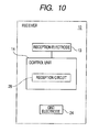
- an embodiment shown in Figs. 9 and 10 is communication directed from the second communication module 40 of the employee ID card 82 only to the first communication module 10 of the door 74.
- a second communication module 40 of this embodiment is a transmitter, and includes a transmission/reception electrode 42 for human body communication and a GND electrode 54 as shown in Fig. 9 .
- the transmission/reception electrode 42 is arranged on the backside of the employee ID card 82 facing clothing of the human body 80.
- the transmission/reception electrode 42 is electrically connected to a control unit 44.
- the control unit 44 includes a transmission circuit 46.
- the transmission circuit 46 includes a transmission output determination unit 48 and an output execution unit 50.
- the transmission output determination unit 48 and the output execution unit 50 have the same function as those of the first communication module 10 of Fig. 2 .
- a memory 52 stores a unique ID of the communication module 40.
- the transmission/reception electrode 42 is electrically connected to an electric field strength measuring unit 62.
- the electric field strength measuring unit 62 measures a noise level of environmental noise picked up by the human body 80.
- the measured noise level is output to the transmission output determination unit 48.
- the transmission output determination unit 48 determines an output level of a transmission signal directed to the communication module 10 by following the measured noise level, and the output execution unit 20 outputs a transmission signal of the determined output level to the first communication module 10.
- the transmission circuit 46 converts the transmission signal of the output level after the determination as a transmission signal of a unique ID of the communication module 40 into an electrical signal.
- the control unit 44 modulates the transmission signal, outputs the modulated transmission signal to the transmission/reception electrode 42, and causes the output modulated transmission signal to reach the first communication module 10.
- the operation by the second communication module 40 corresponds to the content of steps S601 to S604 in Fig. 6 .
- the first communication module 10 is a receiver. As shown in Fig. 10 , a reception electrode 13 and a GND electrode 24 for human body communication are arranged in the first communication module 10.
- the reception electrode 13 is electrically connected to a control unit 14, and a signal detected by the reception electrode 13 is converted into an electrical signal by a reception circuit 28.
- the control unit 14 demodulates the signal and determines whether or not a received ID is a normal ID. When the control unit 14 has determined that the received ID is the normal ID, the second communication module 40 is specified and the door 74 is unlocked.
- the operation by the first communication module 10 corresponds to the content of steps S705 to S707 in Fig. 7 .
- the first communication module 10 of the above-described first and second embodiments includes the electric field strength measuring unit 32 (62), the transmission output determination unit 18 (48), and the output execution unit 20 (50).
- the electric field strength measuring unit 32 measures a noise level of environmental noise from the received electric field strength detected at the time of no signal, and outputs the measurement result to the transmission output determination unit 18 (48).
- the transmission output determination unit 18 (48) determines an output level of the transmission signal to be transmitted to the second communication module 40 (the first communication module 10) on the basis of the measured noise level, and outputs the determination result to the output execution unit 20 (50).
- the output execution unit 20 (50) outputs a transmission signal of the determined output level to the second communication module 40 (the first communication module 10) via the transmission/reception electrode 12 (42).
- a state in which a transmission signal from the first communication module 10 (the second communication module 40) to the second communication module 40 (the first communication module 10) is absent is a state in which environmental noise received by the human body 80 itself is capable of being specified
- the output level of the transmission signal directed to the second communication module 40 (the first communication module 10) may be determined by considering the noise level. As a result, it contributes to the improvement of true communication performance in communication using the human body 80 as a signal transmission path.
- the human body 80 In communication using the human body 80 for the signal transmission path, the human body 80 itself functions as an antenna which picks up environmental noise, and the noise level is particularly increased at the moment when the hand of the human body 80 is in contact with the door knob 76, that is, the transmission/reception electrode 12 of the first communication module 10.
- the noise level is particularly increased at the moment when the hand of the human body 80 is in contact with the door knob 76, that is, the transmission/reception electrode 12 of the first communication module 10.
- the transmission output determination unit 18 (48) determines the output level of the transmission signal directed to the second communication module 40 (the first communication module 10) by following the measured noise level, it is possible to set the output level of the transmission signal to an optimum magnitude commensurate with the noise level. Consequently, the transmission signal directed to the second communication module 40 (the first communication module 10) is not buried in the environmental noise, and it is possible to prevent communication which does not pass through the human body 80 as the signal transmission path.
- the output execution unit 20 of the first communication module 10 in the first and second embodiments outputs the transmission signal to the second communication module 40, but also the transmission signal includes information of the measured noise level or the determined output level. Consequently, for example, the first communication module 10 may also use the information for a subsequent determination of the output level or the like, and the second communication module 40 may also use the information for adjustment or the like upon reception/transmission.
- two-way communication is performed between the first communication module 10 and the second communication module 40 mounted on the human body 80.
- the second communication module 40 mounted on the human body 80 also includes the transmission output determination unit 48 and the output execution unit 50, but the transmission output determination unit 48 determines an output level of a transmission signal to be returned to the first communication module 10 using the information of the noise level measured by the first communication module 10 or the output level determined thereby. Since it is not necessary to measure the noise level in the second communication module 40, it is possible to simplify the configuration or control of the second communication module 40.
- the second communication module 40 mounted on the human body 80 may be started using the transmission signal from the first communication module 10 as a trigger, so that power consumption may be reduced. As a result, the battery life of the second communication module 40 is also lengthened.
- the transmission output determination unit 48 of the second communication module 40 of the first and second embodiments determines the output level of the transmission signal directed to the first communication module 10 by following the measured noise level or the determined output level, it is possible to set the output level of the transmission signal to be returned to an optimum magnitude commensurate with the noise level. Even in two-way communication of the communication modules 10 and 40, the transmission signal directed to the first communication module 10 is not buried in the environmental noise, and it is possible to prevent communication which does not pass through the human body 80 as the signal transmission path.
- the electric field strength measuring unit 32 not only measures the noise level from the received electric field strength at the time of no signal, but also measures the received signal level by the received electric field strength of the transmission signal returned from the second communication module 40.
- the transmission output determination unit 18 re-determines the output level of the transmission signal to be transmitted to the second communication module 40 on the basis of the former noise level and the latter received signal level.
- a high output level is necessary in initial communication when it is possible to re-adjust the output level of the transmission signal directed to the second communication module 40 by considering an actual communication state as described above.
- a low output level is adequate thereafter, it is possible to avoid the transmission by a useless output level and it is possible to reduce power consumption while improving true communication performance.
- the transmission/reception electrodes 12 and 42 are capacitively coupled to the human body 80, thereby receiving or transmitting a signal from or to the human body 80.
- the GND electrode 24 is capacitively coupled to the GND electrode 54 via the ground which is the air or the floor surface 70. A closed loop is formed by all the electrodes.
- Each of the communication modules 10 and 40 uses an electric field generated by voltage application directed to the human body 80, and uses the human body 80 as a signal transmission path. Since a signal of the above-described method is transmitted through clothing or shoes, the transmission/reception electrodes 12 and 42 or the GND electrodes 24 and 54 may perform non-contact communication without making direct contact with the skin of the human body 80. Consequently, the influence of the sweat of the human body 80 or the like on communication is small and general versatility also increases.
- An electric current scheme may be used in which a human body serves as a signal line and a reference line.
Landscapes
- Engineering & Computer Science (AREA)
- Computer Networks & Wireless Communication (AREA)
- Signal Processing (AREA)
- Near-Field Transmission Systems (AREA)
Applications Claiming Priority (1)
| Application Number | Priority Date | Filing Date | Title |
|---|---|---|---|
| JP2009171084A JP5271183B2 (ja) | 2009-07-22 | 2009-07-22 | 通信装置及び通信方法 |
Publications (1)
| Publication Number | Publication Date |
|---|---|
| EP2282425A1 true EP2282425A1 (de) | 2011-02-09 |
Family
ID=42989374
Family Applications (1)
| Application Number | Title | Priority Date | Filing Date |
|---|---|---|---|
| EP10169881A Withdrawn EP2282425A1 (de) | 2009-07-22 | 2010-07-16 | Kommunikationsvorrichtung und Kommunikationsverfahren |
Country Status (3)
| Country | Link |
|---|---|
| US (1) | US8509689B2 (de) |
| EP (1) | EP2282425A1 (de) |
| JP (1) | JP5271183B2 (de) |
Families Citing this family (14)
| Publication number | Priority date | Publication date | Assignee | Title |
|---|---|---|---|---|
| KR20100126958A (ko) * | 2009-05-25 | 2010-12-03 | 삼성전자주식회사 | 멀티 디바이스 제어 방법 및 장치 |
| US9361488B2 (en) | 2010-07-01 | 2016-06-07 | Intelleflex Corporation | Single or dual complex subcarrier downconversion |
| JP2013172389A (ja) * | 2012-02-22 | 2013-09-02 | Nippon Telegr & Teleph Corp <Ntt> | ハイブリッド通信装置 |
| US9819395B2 (en) | 2014-05-05 | 2017-11-14 | Nxp B.V. | Apparatus and method for wireless body communication |
| US9819075B2 (en) | 2014-05-05 | 2017-11-14 | Nxp B.V. | Body communication antenna |
| US9812788B2 (en) * | 2014-11-24 | 2017-11-07 | Nxp B.V. | Electromagnetic field induction for inter-body and transverse body communication |
| US10014578B2 (en) | 2014-05-05 | 2018-07-03 | Nxp B.V. | Body antenna system |
| US10015604B2 (en) | 2014-05-05 | 2018-07-03 | Nxp B.V. | Electromagnetic induction field communication |
| US10009069B2 (en) | 2014-05-05 | 2018-06-26 | Nxp B.V. | Wireless power delivery and data link |
| US9819097B2 (en) | 2015-08-26 | 2017-11-14 | Nxp B.V. | Antenna system |
| JP6047808B1 (ja) * | 2015-12-02 | 2016-12-21 | 株式会社eNFC | 伝送装置、伝送方法、および伝送システム |
| US10320086B2 (en) | 2016-05-04 | 2019-06-11 | Nxp B.V. | Near-field electromagnetic induction (NFEMI) antenna |
| JP2018046352A (ja) * | 2016-09-13 | 2018-03-22 | ソニーセミコンダクタソリューションズ株式会社 | 通信装置、および通信システム |
| US20190265473A1 (en) * | 2018-02-23 | 2019-08-29 | Oculus Vr, Llc | Apparatus, systems, and methods for enabling low-power communications via wearers' bodies |
Citations (7)
| Publication number | Priority date | Publication date | Assignee | Title |
|---|---|---|---|---|
| US5204672A (en) * | 1989-09-13 | 1993-04-20 | Brooks James E | Keyless entry system |
| EP0843425A2 (de) * | 1996-11-14 | 1998-05-20 | International Business Machines Corporation | Elektronische Kommunikationseinrichtung unter Verwendung des menschlichen Körpers als Übertragungsmedium |
| JP2004153708A (ja) | 2002-10-31 | 2004-05-27 | Nippon Telegr & Teleph Corp <Ntt> | トランシーバ |
| EP1598965A1 (de) * | 2003-02-27 | 2005-11-23 | Sony Corporation | Kommunikationssystem |
| JP2007020124A (ja) * | 2005-07-11 | 2007-01-25 | Nippon Telegr & Teleph Corp <Ntt> | 電界通信システム |
| JP2007226560A (ja) * | 2006-02-23 | 2007-09-06 | Nippon Telegr & Teleph Corp <Ntt> | Icカードシステム |
| JP4074661B2 (ja) | 1995-05-08 | 2008-04-09 | マサチューセッツ・インスティテュート・オブ・テクノロジー | 信号伝送媒体として人体を用いた非接触検知及び信号システム |
Family Cites Families (23)
| Publication number | Priority date | Publication date | Assignee | Title |
|---|---|---|---|---|
| US6211799B1 (en) * | 1997-11-06 | 2001-04-03 | Massachusetts Institute Of Technology | Method and apparatus for transbody transmission of power and information |
| US6754472B1 (en) * | 2000-04-27 | 2004-06-22 | Microsoft Corporation | Method and apparatus for transmitting power and data using the human body |
| EP1168678B1 (de) * | 2000-06-27 | 2003-09-03 | Matsushita Electric Works, Ltd. | Datenübertragungssystem unter Verwendung eines menschlichen Körpers als Signalübertragungsweg |
| DE60102331T2 (de) * | 2000-09-08 | 2005-03-17 | Matsushita Electric Works, Ltd., Kadoma | Datenübertragungssystem unter Verwendung eines menschlichen Körpers als Signalübertragungsweg |
| JP2003008481A (ja) * | 2001-06-27 | 2003-01-10 | Denso Corp | Idタグシステム,idタグリーダ及びidタグ |
| JP3610496B2 (ja) | 2002-07-30 | 2005-01-12 | オリオン電機株式会社 | プリント基板及び電子部品のハンダ付け構造 |
| JP4507058B2 (ja) * | 2003-06-05 | 2010-07-21 | ソニー株式会社 | 距離検出システム |
| JP4257361B2 (ja) * | 2003-06-30 | 2009-04-22 | 日本電信電話株式会社 | 電界検出光学装置及びトランシーバ |
| US20060064142A1 (en) * | 2004-09-17 | 2006-03-23 | Cardiac Pacemakers, Inc. | Systems and methods for deriving relative physiologic measurements using an implanted sensor device |
| JP4478160B2 (ja) * | 2004-12-02 | 2010-06-09 | 日本電信電話株式会社 | 送信器、電界通信トランシーバおよび電界通信システム |
| WO2006064397A2 (en) * | 2004-12-13 | 2006-06-22 | Koninklijke Philips Electronics N.V. | Mobile monitoring |
| JP4586618B2 (ja) * | 2005-04-18 | 2010-11-24 | ソニー株式会社 | 人体通信システム及び通信装置 |
| JP4257611B2 (ja) * | 2005-05-17 | 2009-04-22 | ソニー株式会社 | 通信装置および方法、並びにプログラム |
| US20080123599A1 (en) * | 2005-07-25 | 2008-05-29 | Yoshihito Ishibashi | Communication System, Communication Device And Method, And Program |
| KR100723307B1 (ko) * | 2005-10-25 | 2007-05-30 | 한국전자통신연구원 | 통신 장치 |
| JP4191736B2 (ja) * | 2006-01-11 | 2008-12-03 | 日本電信電話株式会社 | 電界通信システム |
| JP4348637B2 (ja) * | 2006-01-16 | 2009-10-21 | ソニー株式会社 | 通信装置 |
| EP1848131A4 (de) * | 2006-01-25 | 2013-03-27 | Nippon Telegraph & Telephone | Empfänger, sende-empfänger und auf elektrischem feld basierendes kommunikationssystem |
| US7557712B2 (en) * | 2006-09-29 | 2009-07-07 | Hewlett-Packard Development Company, L.P. | Systems and method for monitoring equipment |
| EP1926223B1 (de) * | 2006-11-21 | 2018-02-28 | Sony Corporation | Kommunikationssystem und kommunikationsvorrichtung |
| CN101627565B (zh) * | 2007-03-16 | 2014-03-12 | 阿尔卑斯电气株式会社 | 通信系统 |
| JP5166131B2 (ja) * | 2008-06-13 | 2013-03-21 | オンセミコンダクター・トレーディング・リミテッド | 通信システム及びそれに用いられる受信装置 |
| JP2010252279A (ja) * | 2009-04-20 | 2010-11-04 | Sony Corp | 通信装置 |
-
2009
- 2009-07-22 JP JP2009171084A patent/JP5271183B2/ja not_active Expired - Fee Related
-
2010
- 2010-07-16 EP EP10169881A patent/EP2282425A1/de not_active Withdrawn
- 2010-07-22 US US12/841,579 patent/US8509689B2/en not_active Expired - Fee Related
Patent Citations (7)
| Publication number | Priority date | Publication date | Assignee | Title |
|---|---|---|---|---|
| US5204672A (en) * | 1989-09-13 | 1993-04-20 | Brooks James E | Keyless entry system |
| JP4074661B2 (ja) | 1995-05-08 | 2008-04-09 | マサチューセッツ・インスティテュート・オブ・テクノロジー | 信号伝送媒体として人体を用いた非接触検知及び信号システム |
| EP0843425A2 (de) * | 1996-11-14 | 1998-05-20 | International Business Machines Corporation | Elektronische Kommunikationseinrichtung unter Verwendung des menschlichen Körpers als Übertragungsmedium |
| JP2004153708A (ja) | 2002-10-31 | 2004-05-27 | Nippon Telegr & Teleph Corp <Ntt> | トランシーバ |
| EP1598965A1 (de) * | 2003-02-27 | 2005-11-23 | Sony Corporation | Kommunikationssystem |
| JP2007020124A (ja) * | 2005-07-11 | 2007-01-25 | Nippon Telegr & Teleph Corp <Ntt> | 電界通信システム |
| JP2007226560A (ja) * | 2006-02-23 | 2007-09-06 | Nippon Telegr & Teleph Corp <Ntt> | Icカードシステム |
Also Published As
| Publication number | Publication date |
|---|---|
| US8509689B2 (en) | 2013-08-13 |
| US20110021148A1 (en) | 2011-01-27 |
| JP2011029752A (ja) | 2011-02-10 |
| JP5271183B2 (ja) | 2013-08-21 |
Similar Documents
| Publication | Publication Date | Title |
|---|---|---|
| US8509689B2 (en) | Communication device and communication method | |
| US10008062B2 (en) | Multiple-band identification and ranging | |
| US11877204B2 (en) | Electronic apparatus and method for controlling function on basis of location and direction of object | |
| US9554286B2 (en) | Apparatus and method for detecting a location of a wireless device | |
| EP1982876B1 (de) | Schlüsselloses Zugangssystem | |
| EP2612795A1 (de) | Drahtlose Kommunikationsschaltung | |
| US10124763B2 (en) | Keyless entry apparatus | |
| CN110447054A (zh) | 用于激活车辆功能的方法 | |
| CN104063928A (zh) | 一种基于高频天线特征判别的智能锁系统 | |
| JP6895635B2 (ja) | 電気錠システム及び電気錠装置 | |
| US20210204136A1 (en) | Relay station attack prevention | |
| CN103985177A (zh) | 基于受限交互的被动式智能锁系统 | |
| JP5134560B2 (ja) | 入退場管理システム | |
| EP2799293B1 (de) | Passiveingabe- und Passivstartsystem mit Bedienergeherkennung | |
| CN103971439A (zh) | 一种基于受限交互的被动式智能锁系统 | |
| CN103971438A (zh) | 基于高频天线特征判别的智能锁系统 | |
| CN202177936U (zh) | 一种远距离门禁系统 | |
| KR20150006560A (ko) | 디지털 도어 락의 소비 전력 감소를 통한 배터리 수명 연장 방법 및 이를 이용한 디지털 도어락 시스템 | |
| US20210094509A1 (en) | Systems and methods for access control using field strength | |
| US20210142599A1 (en) | Portable machine | |
| KR20210058154A (ko) | 차량 내 무선충전기 | |
| KR20210013438A (ko) | Rf 신호를 이용한 저전력 스마트키 도어락 시스템 | |
| US11438028B2 (en) | Communication set-up for wireless communication and method for controlling such a communication set-up | |
| JP2009017052A (ja) | 電界通信システムおよび電界通信方法 | |
| KR20160034579A (ko) | 트랜스폰더 및 이를 이용한 무선 충전 장치 및 방법과 이를 이용하는 차량 |
Legal Events
| Date | Code | Title | Description |
|---|---|---|---|
| PUAI | Public reference made under article 153(3) epc to a published international application that has entered the european phase |
Free format text: ORIGINAL CODE: 0009012 |
|
| AK | Designated contracting states |
Kind code of ref document: A1 Designated state(s): AL AT BE BG CH CY CZ DE DK EE ES FI FR GB GR HR HU IE IS IT LI LT LU LV MC MK MT NL NO PL PT RO SE SI SK SM TR |
|
| AX | Request for extension of the european patent |
Extension state: BA ME RS |
|
| 17P | Request for examination filed |
Effective date: 20110718 |
|
| STAA | Information on the status of an ep patent application or granted ep patent |
Free format text: STATUS: THE APPLICATION HAS BEEN WITHDRAWN |
|
| 18W | Application withdrawn |
Effective date: 20160928 |