EP2280552B1 - Système pour projections et visualisation d'images en 3D - Google Patents
Système pour projections et visualisation d'images en 3D Download PDFInfo
- Publication number
- EP2280552B1 EP2280552B1 EP10188344.5A EP10188344A EP2280552B1 EP 2280552 B1 EP2280552 B1 EP 2280552B1 EP 10188344 A EP10188344 A EP 10188344A EP 2280552 B1 EP2280552 B1 EP 2280552B1
- Authority
- EP
- European Patent Office
- Prior art keywords
- filter
- filters
- viewing
- passbands
- approximately
- Prior art date
- Legal status (The legal status is an assumption and is not a legal conclusion. Google has not performed a legal analysis and makes no representation as to the accuracy of the status listed.)
- Active
Links
Images


Classifications
-
- G—PHYSICS
- G02—OPTICS
- G02B—OPTICAL ELEMENTS, SYSTEMS OR APPARATUS
- G02B26/00—Optical devices or arrangements for the control of light using movable or deformable optical elements
- G02B26/007—Optical devices or arrangements for the control of light using movable or deformable optical elements the movable or deformable optical element controlling the colour, i.e. a spectral characteristic, of the light
- G02B26/008—Optical devices or arrangements for the control of light using movable or deformable optical elements the movable or deformable optical element controlling the colour, i.e. a spectral characteristic, of the light in the form of devices for effecting sequential colour changes, e.g. colour wheels
-
- G—PHYSICS
- G02—OPTICS
- G02B—OPTICAL ELEMENTS, SYSTEMS OR APPARATUS
- G02B30/00—Optical systems or apparatus for producing three-dimensional [3D] effects, e.g. stereoscopic images
-
- G—PHYSICS
- G02—OPTICS
- G02B—OPTICAL ELEMENTS, SYSTEMS OR APPARATUS
- G02B30/00—Optical systems or apparatus for producing three-dimensional [3D] effects, e.g. stereoscopic images
- G02B30/20—Optical systems or apparatus for producing three-dimensional [3D] effects, e.g. stereoscopic images by providing first and second parallax images to an observer's left and right eyes
- G02B30/22—Optical systems or apparatus for producing three-dimensional [3D] effects, e.g. stereoscopic images by providing first and second parallax images to an observer's left and right eyes of the stereoscopic type
- G02B30/23—Optical systems or apparatus for producing three-dimensional [3D] effects, e.g. stereoscopic images by providing first and second parallax images to an observer's left and right eyes of the stereoscopic type using wavelength separation, e.g. using anaglyph techniques
-
- G—PHYSICS
- G02—OPTICS
- G02B—OPTICAL ELEMENTS, SYSTEMS OR APPARATUS
- G02B30/00—Optical systems or apparatus for producing three-dimensional [3D] effects, e.g. stereoscopic images
- G02B30/20—Optical systems or apparatus for producing three-dimensional [3D] effects, e.g. stereoscopic images by providing first and second parallax images to an observer's left and right eyes
- G02B30/34—Stereoscopes providing a stereoscopic pair of separated images corresponding to parallactically displaced views of the same object, e.g. three-dimensional [3D] slide viewers
-
- G—PHYSICS
- G02—OPTICS
- G02B—OPTICAL ELEMENTS, SYSTEMS OR APPARATUS
- G02B5/00—Optical elements other than lenses
- G02B5/20—Filters
- G02B5/28—Interference filters
- G02B5/285—Interference filters comprising deposited thin solid films
-
- G—PHYSICS
- G02—OPTICS
- G02C—SPECTACLES; SUNGLASSES OR GOGGLES INSOFAR AS THEY HAVE THE SAME FEATURES AS SPECTACLES; CONTACT LENSES
- G02C7/00—Optical parts
- G02C7/10—Filters, e.g. for facilitating adaptation of the eyes to the dark; Sunglasses
- G02C7/104—Filters, e.g. for facilitating adaptation of the eyes to the dark; Sunglasses having spectral characteristics for purposes other than sun-protection
-
- H—ELECTRICITY
- H04—ELECTRIC COMMUNICATION TECHNIQUE
- H04N—PICTORIAL COMMUNICATION, e.g. TELEVISION
- H04N13/00—Stereoscopic video systems; Multi-view video systems; Details thereof
- H04N13/30—Image reproducers
- H04N13/324—Colour aspects
-
- H—ELECTRICITY
- H04—ELECTRIC COMMUNICATION TECHNIQUE
- H04N—PICTORIAL COMMUNICATION, e.g. TELEVISION
- H04N13/00—Stereoscopic video systems; Multi-view video systems; Details thereof
- H04N13/30—Image reproducers
- H04N13/332—Displays for viewing with the aid of special glasses or head-mounted displays [HMD]
- H04N13/334—Displays for viewing with the aid of special glasses or head-mounted displays [HMD] using spectral multiplexing
-
- H—ELECTRICITY
- H04—ELECTRIC COMMUNICATION TECHNIQUE
- H04N—PICTORIAL COMMUNICATION, e.g. TELEVISION
- H04N13/00—Stereoscopic video systems; Multi-view video systems; Details thereof
- H04N13/30—Image reproducers
- H04N13/363—Image reproducers using image projection screens
Definitions
- the present invention relates viewing systems and products for projecting and viewing spectrally separated 3-Dimensional (3D) images.
- the invention is also related to viewing systems used in a Digital Cinema (D-Cinema) Theatre and improves current methods for projecting and viewing a 3D stereoscopic movie.
- D-Cinema Digital Cinema
- Methods for 3D stereoscopic projection include Anaglyph, Linear Polarization, Circular Polarization, Shutter Glasses, and Spectral Separation.
- Anaglyph is the oldest technology, and provides left/right eye separation by filtering the light through a two color filter, commonly red for one eye, and cyan for the other eye.
- the left eye image is (commonly) filtered through a red filter, and the right image filtered through a cyan filter.
- the eyewear includes, for example, a red filter for the left eye, and a cyan filter for the right eye. This method works best for black and white original images, and is not well suited for color images.
- Linear Polarization 3D provides separation at the projector by filtering the left eye through a linear polarizer (commonly) oriented vertically, and filtering the right eye image through a linear polarizer oriented horizontally.
- the eyewear includes a vertically' oriented linear polarizer for the left eye and a horizontally oriented polarizer for the right eye.
- the projection screen must be of the polarization preserving type, commonly referred to as a "silver screen" because of its distinctive color.
- Linear Polarization allows a full color image to be displayed with little color distortion. It has several problems, these include the need for a silver screen which is expensive, fragile, and not uniform. Another problem is that the viewer must keep his head oriented vertically to avoid crosstalk from one eye to another.
- Circular Polarization 3D was invented to address the problem of requiring the viewer to keep his head oriented vertically.
- Circular Polarization provides separation at the projector by filtering the left eye image through a (commonly) left handed circular polarizer, and filtering the right eye image through a right handed circular polarizer.
- the eyewear includes a left handed circular polarizer for the left eye and a right handed circular polarizer for the right eye.
- a silver screen is also needed for this approach.
- Shutter Glasses provides separation by multiplexing the left and right images in time. A filter for separation at the projector is not required.
- the eyewear includes Shutter Glasses. These are active glasses that electronically shutter the lens in synchrony with the projector frame rate. The left eye image is first displayed, followed by the right eye image etc. Since having a direct wired connection to the Glasses in a theatre is impractical, a wireless or infrared signaling method is used to provide a timing reference for the left/right eye shuttering. This method requires an IR or RF transmitter in the auditorium.
- the Shutter Glasses are expensive and hard to clean, require batteries that must be frequently replaced, and are limited in their switching rate. Shutter glasses are only practical for use with D-Cinema or other electronic projection systems since very few film projectors provide the signal required to synchronize the shutter glasses with the frame rate. The method does not require a silver screen.
- Spectral Separation provides separation at the projector by filtering the left and right eye spectrally.
- the system differs from anaglyph in that the filters for the left and right eye each pass a portion of the red, green, and blue spectrum, providing for a full color image.
- the band pass spectrum of the left eye filter is complementary to the band pass spectrum of the right eye filter.
- the eyewear includes filters with the same general spectral characteristics as are used in the projector. While this method provides a full color image, it requires color compensation to make the colors in the left and right eye match the colors that were present in the original image, and there is a small reduction in the color gamut compared to the gamut of the projector.
- All of the above methods for providing left/right eye separation for a 3D Stereoscopic presentation can be used with either two projectors (one for the left eye and one for the right eye), or may be used with a single D-Cinema projector system.
- the projection filter In the dual projection system, the projection filter is usually static, and is located in front of the projection lens.
- the left and right images are time multiplexed. Except for the Shutter Glasses case where no projection filters are required, this means that the projection filters must change at the L/R multiplex frequency. This can be done with either a filter wheel in the projector synchronized to the multiplex frequency, or with an electronically switched filter.
- WO 2005/039192 A1 discloses a stereoscopic projection system that uses notch filters instead of bandpass filters.
- US 2005/036119 A1 discloses an optical system for use in projection based displays includes a plurality of solid state light sources associated with a plurality of total internal reflection based compound hyperbolic emitters, a graduated dichroic filter based device for homogenizing light output from the plurality of solid state light sources, a ferro-electric liquid crystal on silicon device for illumination with light output from the array of solid state light sources, and a polarization diffuser for homogenization of light at the ferro-electric liquid crystal on silicon device.
- WO 98/49837 A1 discloses an image projection system that is intended for image projection in bright environments.
- a projector light has a number of spectrum peaks in the visible wavelength range, and eyeglasses are used that have corresponding, very narrow spectrum peaks. This arrangement blocks ambient light a wavelengths outside the spectrum peaks.
- the present inventors have realized the need for improvements in spectrally separated viewing devices and systems.
- the invention provides several techniques to remove and compensate for blue shift that occurs when viewing images through filters at off-axis (other than normal) angles.
- the blue shift is undesirable because it can result in crosstalk between left and right images in a 3D image presentation.
- the present inventors have also realized the need for improvements in spectral separation filters, and particularly those used in 3D D-Cinema applications.
- One problem realized is that typical 3-D projection systems have low luminance efficiency in that color spaces, color gamut, and effective brightness are inadequate.
- Another problem realized is that imbalance between luminance levels in channels of 3D projections decreases luminal efficiency. Accordingly, as described in more detail below, examples that are useful for understanding the present invention also provide techniques to increase the color space and luminal efficiency of projected images that may be used alone or in combination with blue shift compensation techniques according to the present invention.
- one or more techniques to increase the color space of spectrally separated images may be combined with one or more techniques to compensate for blue shift that occurs when viewing spectrally separated images through filters at other than normal angles.
- the individual techniques are further described herein.
- a system comprising a 3D projection device using asymmetric projection filters may be combined with viewing glasses according to the present invention comprising lenses with spectrally complementary filters.
- a pair of 3D spectral separation filters is provided, disposed on left and right lenses of a pair of viewing glasses, the eye filters comprising a combination of increased (and proportional to wavelength) guard bands, and appropriately curved lenses to reduce crosstalk, color shift, and reflections at the edge of the field of view.
- a blue shifted color filter in a projector that projects images for viewing through the glasses may also be utilized.
- viewing filters comprising a non-flat substrate and spectrally complementary filters.
- spectral separation viewing glasses comprising, a first lens having a first spectral filter, and a second lens having a second spectral filter spectrally complementary to the first spectral filter, wherein the first lens and the second lens are each curved to reduce the wavelength shift that occurs when viewing an image at other than an angle normal to a filter through which the image is being viewed.
- An amount of curvature of the lenses (and hence the filters) is calculated such that viewing angles across a viewing screen are closer to normal angles through the lenses.
- the curvature is implemented, for example, as a spherical curve.
- spectral separation viewing glasses comprising, a first lens comprising a first spectral filter, and a second lens comprising a second spectral filter spectrally complementary to the first spectral filter, wherein the first spectral filter and the second spectral filter have at least one guard band between adjacent portions of spectrum of the spectral filters.
- the guard band has a bandwidth sufficient to remove crosstalk of spectrally separated images viewed through the glasses, and, for example, is calculated based on an amount of wavelength shift occurring when viewing portions of the spectrally separated images at an angle through the filters.
- a spectral separation viewing system comprising, viewing glasses according to the present invention and a projection system configured to project first and second spectrally separated images wherein the images are wavelength pre-shifted to compensate for wavelength shifts occurring during display and/or viewing of the images.
- Such systems are preferably implemented in a commercial movie theater, but are also applicable to large screen televisions, computers, virtual reality systems, and other display devices.
- a method comprising the steps of, projecting first and second spectrally separated images onto a display screen, viewing the projected images through a pair of glasses having a first lens having a first spectral filter matching the first spectrally separated image and a second lens having a second spectral filter matching the second spectrally separated image, wherein the spectral filters are configured to have a varying amount of wavelength shift effect depending upon a viewing angle through the lens.
- a 3D viewing system comprising, means for projecting spectrally separated images, means, according to the present invention, for viewing the spectrally separated images through different ocular channels, and means, according to the present invention, for compensating for wavelength shifts occurring due to viewing angles to portions of the images.
- the means for compensating may include, for example, means for adjusting an amount of spectral filtering performed on different portions of the image based on viewing angle.
- the means for compensating includes, for example, means for producing a wavelength mismatch between projector filters and eye filters that compensates for an amount of wavelength shift that occurs in the eye filters due to viewing angle.
- shaped glasses comprising a pair of spectrally complementary filters disposed on lenses of the glasses.
- the lenses may be curved.
- the spectrally complementary filters may include guard bands between adjacent spectrums of the spectrally complementary filters.
- the thickness of dielectric layers of the spectrally complementary filters increases toward edges of the lenses.
- a method comprising the steps of, distributing shaped glasses to audience viewers, and projecting first and second spectrally complementary images on a display screen within view of the audience members, wherein the shaped glasses comprise first and second shaped lenses having first and second spectrally complementary filters respectively disposed thereon.
- the first and second spectrally complementary filters respectively correspond in bandwidth to the projected first and second spectrally complementary images.
- the filters are not necessarily required to correspond exactly with the projected images of the filters.
- the shaped glasses comprise, for example, spherically shaped lenses.
- a storage medium having at least a visual performance stored thereon, that, when loaded into a media player coupled to a display device, causes the media player to transmit the visual performance for display to the display device; wherein the visual performance as displayed on the display device is configured for viewing through a pair of shaped glasses according to the present invention.
- the storage medium is, for example, prepackaged with at least one pair of shaped glasses and available for purchase via a retail outlet.
- a system for viewing 3D images, comprising, serving 3D content over a network to a receiving electronic device, and displaying the 3D content, wherein the 3D content comprises spectrally complementary images intended to be viewed with spectrally separated shaped glasses according to the present invention.
- the receiving electronic device is, for example, a display system located at a movie theater.
- the present invention addresses some of the problems with the Spectral Separation method for projecting 3D images, specifically an improvement in the efficiency, increase in the color gamut, and a reduction in the amount of color compensation required. In some cases, the color compensation may not be required.
- the efficiency and color space issues by splitting primary colors of the projector into subparts is addressed.
- the splitting of primary colors into subparts is accomplished in part through the filter installed in the projector, which is the main controlling factor in the color space of the system.
- the efficiency and color gamut of the projected image are both increased using the additional subparts of the split primary colors.
- a projector filter comprising, a first filter having a first set of primary passbands, and a second filter having a second set of primary passbands, wherein the first set of primary passbands has a different number of primary passbands than the second filter.
- the first filter has, for example, at least two blue primary passbands and the second filter has at least one blue primary passband.
- the first filter may also have, for example, at least two green primary passbands and the second filter has at least one green primary.
- the first filter may have passband wavelengths of approximately 400 to 440 nm and 484 to 498 nm, 514 to 528 nm, 567 to 581 nm, and 610 to 623 nm
- the second filter may have passband wavelengths of approximately 455 to 471 nm, 539 to 556 nm, and 634 to 700 nm.
- the passbands of the first filter and the second filter are, for example, selected to maximize reproduction of a color space of a D-Cinema projector.
- a system for projection of spectrally separated 3D images, comprising, a projection system configured to project left and right channel images for display by a viewer, a filter placed in at least one light path of the projection system comprising a left channel filter and a right channel filter, wherein at least one of the left and right channel filters has more than 3 primary passbands.
- one of the left and right channel filters has at least 2 primary passbands in blue wavelengths and one of the left and right channel filters has at least 2 primary passbands in green wavelengths.
- the primary passbands of the filters are selected to maximize reproduction of a color space of the projection system in images projected by the projection system.
- the system may include, for example, a color correction module configured to color correct images projected by the projection system according to a color space of the filters.
- a set of filters comprising a first filter having a first set of primary color passbands, a second filter having a second set of primary color passbands of different wavelengths compared to the first set of primary colors, wherein the first filter has more than one primary color in at least one color band.
- a method comprising the steps of, preparing a 3D image comprising a left image and a right image, filtering the left image with a left channel filter, filtering the right image with a right channel filter, and projecting the left and right filtered images onto a screen, wherein at least one of the left channel filter and right channel filter have more than 3 primary passbands.
- the filters may themselves be embodied in an electronically switchable filter set, fixed filters in a two projector system, or a filter wheel wherein approximately 1 ⁇ 2 the wheel has filter characteristics of a left channel filter according to this example and approximately 1 ⁇ 2 the wheel has filter characteristics of a right channel filter according to this example.
- Portions of the described examples may be conveniently implemented in programming on a general purpose computer, or networked computers, and the results may be displayed on an output device connected to any of the general purpose, networked computers, or transmitted to a remote device for output or display.
- the examples may include the utilization of software that implements color processing separately on each ocular channel.
- Any components of the examples represented in a computer program, data sequences, and/or control signals may be embodied as an electronic signal broadcast (or transmitted) at any frequency in any medium including, but not limited to, wireless broadcasts, and transmissions over copper wire(s), fiber optic cable(s), and co-axial cable(s), etc.
- This invention addresses some of the problems with the Spectral Separation method for projecting 3D images, specifically this invention aims to improve the off-axis filter characteristics when thin film dielectric (interference) filters (e.g., right eye and left eye filters) are used to implement eyewear (e.g., glasses) for viewing spectrally separated images.
- thin film dielectric (interference) filters e.g., right eye and left eye filters
- eyewear e.g., glasses
- Glasses currently used for spectral separation consist of flat interference filters located about 2 cm in front of the viewer's eyes.
- 3D Cinema theatre e.g., 3D D-Cinema
- the light from the screen does not pass through the interference filters at a single angle.
- the light from the center of the screen would pass through the interference filters of the glasses at a normal (perpendicular) angle (assuming the viewer's head is positioned such that the plane of the interference filters is parallel to the plane of the screen).
- light from the edge of the screen would pass through the interference filters at an angle of about 26 degrees.
- This viewing position is reasonably close to the screen, but is not abnormal; many of the seats in a common auditorium are located closer, and angles of 40 degrees are possible.
- a 26 degree angle from the edge of the screen would have the effect of shifting the filter response toward the blue by about 14 nanometers (nm), and would somewhat distort the filter shape.
- the resulting 3D image appears to have noticeable color shift and increased left/right eye crosstalk towards the edges of the screen.
- the blue shift at the interference filters is primarily important because it causes a mismatch between spectral characteristics of the projector filter (e.g., a filter wheel or electronically switched filter) and the glasses, or more precisely, a mismatch between the spectra of light forming the images (from whatever source) and the characteristics of the glasses at a given viewing angle.
- the projector filter e.g., a filter wheel or electronically switched filter
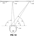
- FIG. 1A there are illustrated example viewing angles through glasses 1110 for a viewer 1100 of an image projected onto a movie screen 1120.
- the viewing angles range from normal to somewhat oblique (e.g., approximately ⁇ 1 to ⁇ 3 , respectively).
- the glasses 1110 include lenses with dielectric based interference filters.
- the non-normal viewing angles have an amount of blue-shift associated with the viewed image that increases with greater obliqueness of the viewing angle through the interference filters.
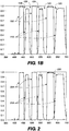
- Fig. 1B illustrates characteristics of exemplary filters used for 3D spectral separation. As shown in Fig. 1B , bandwidths for a left projection filter 100, and a right eye filter 110, includes guard bands 120, 122, 124, 126, and 128 which appear as notches between adjacent light bands ( Fig. 1B illustrates the right eye filter and the left projection filter; the right eye filter approximately represents bandwidths of the right projection filter and the left projection filter approximately represents bandwidths of the left eye filter).
- the left and right eye filters are complementary in that the filter properties of the left eye filter (approximately represented by the left projection filter 100) complement the filter properties of the right eye filter 110. It is not a full complement in that the guard bands keep the combined filters from passing the entire portion of the spectrum between the longest and shortest wavelengths passed by the filters. Further, additional differences in bandwidth within the ranges of the various bands passed by the filters may be made so as to accommodate engineering decisions regarding color space issues that need to be addressed for a particular application.
- Another approach is to pre-blue shift characteristics of the projector filter, or red shift the eye filters, such that for viewing at a normal angle of incidence through the eye filters, the filter characteristics are red shifted with respect to the projector filter.
- This increases the crosstalk and color shift for normal (on axis) viewing, but this can be tuned such that for on axis viewing the crosstalk and color shift is not objectionable.
- the performance is improved since the difference between the projector filters and the blue shifted (off-axis) eye filters is lower.
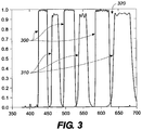
- Fig. 2 and Fig. 3 describe this situation.
- a left projector filter 200, and a blue shifted right eye filter 210 have guard bands including guard band 220 separating adjacent bands of light).
- a blue shifted left projector filter 300 and a blue shifted right eye filter 310 have guard bands including guard band 320 separating adjacent bands of light.
- the notch (guard bands 210 and 310) separating the adjacent bands of light is larger in Fig. 3 .
- Another approach is to curve the filters, which can be implemented, for example, by disposing the eye filters on curved lenses of viewing glasses. This has the advantage that it has the potential of actually reducing the blue shift.
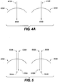
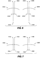
- Fig. 4A describes the geometry of curved lenses with a radius centered at the eye pupil.
- the lenses shown (lens 405A having optical axis 410A and lens 405B having optical axis 410B) have a width of 50mm and the chord is located 20mm from a respective pupil (and center of curvature) (e.g., 400A and 400B).
- the measurements were made for the inventor's eyes, but are representative of the general situation that could be implemented for anyone wearing 3D glasses.
- Using glasses with lenses having a spherical section with a radius centered on the entrance pupil of the eye virtually eliminates any blue shift in the filters because the light passes through the lenses (and hence, the filters) virtually normal to the lens/filter for viewing all parts of the screen.
- Fig. 4B illustrates two views of a pair of glasses 490 having curved lenses 492A and 492B which are both spherically shaped and having spectrally complementary dielectric filters disposed thereon (left eye filter 496A and right eye filter 496B).
- curvatures of the lenses so implemented are distinguished from prescription glasses in that the implemented curvatures are not to correct vision. Nevertheless, in one embodiment, the curvature of the invention may be implemented over or in addition to other lens characteristics intended to fulfill a viewer's prescription needs.
- the curved lens solution still has some limitations.
- the interpupillary distance of eyes varies significantly, and this would mean that glasses designed for the mean would be improperly curved for someone with other than the mean distance. For example, with a child the situation may result in an angle of about 10 degrees for viewing of the center of the screen. As shown in Fig. 5 , the location of a child's pupils (510A and 510B) and the resulting optical axis of the child's eye (530A and 530B) is displaced off the corresponding optical axis of the glasses (520A and 520B respectively centered at center of curvatures 500A and 500B).
- the lenses may use a non-spherical curvature, such as a cylindrical curvature where the lenses are only curved from left to right, and there is no curvature in the vertical direction.
- a non-spherical curvature such as a cylindrical curvature where the lenses are only curved from left to right, and there is no curvature in the vertical direction.
- the screens always have an aspect ratio such that the horizontal extent (e.g., width) is about twice the vertical extent (e.g., height).
- a curvature that is non spherical in either direction such as a multiple radius surface, or one that follows a specific mathematical function.
- a final approach involves the design of the interference filters. This approach requires changing the thickness of the dielectric layers as a function of the distance from the center of each eye filter. If the thicknesses of the dielectric layers are increased at the edges of the filters such that they cause a red shift in the filter characteristics, this can be used to compensate for the blue shift caused by the angle change at the edges of the field of view through the filters.
- the thickening of the dielectric layers may increase manufacturing costs due to difficulty in implementing the increased thicknesses at different points on the flat glass.
- some thickening occurs during the coating process. This approach therefore becomes a practical adjunct to the curved lens solution.
- the guard bands between left and right eye filters should be greater than approximately 2% (e.g., 2.2%) of the wavelength of that filter band. For example, for a filter with a left/right crossover at 640 nm, the guard band should be approximately 14 nm.
- the combined manufacturing tolerance from the projector filters and the eye filters reduces this to about 9 nm.
- the 9 nm guard band that remains can be used for accommodating the blue shift caused by the light going through the left and right eye filters at an angle.
- the angle through the left and right eye filters that causes a 9 nm shift is about 20 degrees. If the curvature of the eye filters (e.g., curvature of lenses upon which the eye filters are disposed or incorporated) is adjusted to allow the light from the edge of the eye filters to pass through to the eye at a maximum of 20 degrees relative to the normal of the eye filters at the edge, then serious degradation of the image at the edge of the eye filters will not occur.
- the radius of curvature needed to achieve this is approximately 50 mm.
- the radius of curvature may be somewhat greater than 50mm to accommodate the pupil shift when the eye is turned to observe the side of the picture screen.
- Fig. 7 shows left and right lenses 705A and 705B with a non-spherical curve (adult pupils 700A, 700B; optical axis of the lenses 715A, 715B; child pupils 710A, 710B, and corresponding optical axis of child's eye 720A, 720B).
- the left and right lenses incorporate corresponding left and right eye filters.
- the filters are, for example, disposed on one or more surfaces of the lenses.
- the advantages of a non-spherical curve are found in accommodating variations of interpupillary distances between different viewers.
- a non-uniform dielectric coating can be used to red shift the filter characteristics at the edges of the filters, further improving the performance.
- a more important advantage is that reflections from behind the viewer are reduced by the curvature. This is important because the interference filters disposed on the eyeglass lenses reflect light that is not transmitted, and are therefore quite reflective. Without the curve, the audience behind the viewer is visible across much of the back side of the lens. With the curve, only a portion (or none) of the lens has a reflection from behind the viewer.
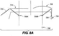
- Fig. 8 illustrates this advantage by comparison of a curved lens 705 having a center of curvature at 708 and a flat lens 710. With respect to the flat lens 710, a relatively wide angled light ray 725 from behind the viewer is reflected off the flat lens into the viewer's pupil 700A.
- a relatively narrow angle (light ray 720) can reach the viewer's pupil 700B via reflection from the curved lens.
- the viewer's temple 730 blocks most light rays sufficiently narrow to enter the viewer's temple.
- interpupillary spacing is directly related to head width and girth.
- adults have larger width and girth, and wider interpupillary spacing, while children are smaller in these dimensions.
- a viewer would wear glasses with the left and right eye filters disposed on corresponding left and right lenses of the glasses where the interocular spacing of the lenses is optimized for the viewer's particular interpupillary distances.
- the bridge of the glasses is designed to flex slightly with head size variation due to pressure on the frame (e.g., pressure exerted on the temple portion of the frames). This flexing results in dihedral angle changes.
- Fig. 8B wider heads 875 with (statistically) larger interpupillary spacing have a larger dihedral angle ⁇ A .
- the dihedral angle is defined as the angle between a planes extending through endpoints on opposite ends of the lenses (see dashed line in Fig. 8B ).
- Smaller heads 880 would have a smaller dihedral angle ⁇ B . With a smaller head and corresponding smaller dihedral angle between the lenses, the distance between the forward directed radii of the curved lenses is reduced to more closely match the smaller interpupillary spacing.
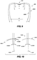
- Fig. 9 illustrates both cases.
- Glasses 900 are illustrated in a first position 900A as when worn by an adult with a relatively larger sized head.
- Interpupillary spacing of the adult is represented by Y.
- a temple or "around the ear" portion of the frame of the glasses have a spacing represented by Y' to accommodate the adult's head size, causing a flex of the bridge 910 of the glasses and resulting in a larger dihedral angle between the lenses.
- Position 900B is similar to that when worn by a child with a relatively smaller sized head, and the interpupillary distance of the child is represented by X.
- the bridge 910 is less flexed because the temple or "around the ear " spacing is reduced to X' which results in a smaller dihedral angle between the lenses. The smaller dihedral angle accommodates the child's smaller interpupillary spacing as described above.
- Fig. 10 illustrates details for the lenses.
- an adult right eye pupil 1010A is shown relative to a child's eye pupil 1015A), with the lens 1020 having a center of curvature at 1025A.
- a larger dihedral exists between the lenses. This is the appropriate lens configuration for an adult.
- an amount of flex of the bridge of the glasses cause lenses 1030 and 1020 to decrease in dihedral as illustrated by 1050 for the left eye (consistent with Fig. 9 , a similar dihedral decrease (not shown) occurs for the right eye in lens 1020).
- the center of the radius of curvature (1040 for lens 1030 in position 1030B) has shifted from an alignment corresponding to the adult pupil 1010B to an alignment corresponding to the child's pupil 1015B.
- Figs. 8B , 9, and 10 are illustrative of an accommodation for both "adult sized” and “child sized” heads and interpupillary distances.
- interpupillary distances and head sizes vary amongst the entire population. While near perfect alignment may occur for some viewers, it is not required and the embodiments illustrated function to accommodate the varying head sizes and interpupillary distances by improving the viewing angle alignments in most cases.
- the lenses shown in Fig. 10 have a 50mm radius of curvature and the dihedral angle is 2 degrees.
- the dihedral angle change for the average adult verses child is about 5 degrees (approximately 2.5 degrees accounted for on each side of the frames for a total of about 5 degrees).
- This technique works best with lenses with a radius of curvature that is about half the length of the temple portion of the glasses.
- the Spectral Separation method for projecting 3D images specifically an improvement in the efficiency, increase in the color gamut, and a reduction in the amount of color compensation required. In some cases, the color compensation may not be required.
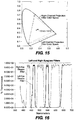
- Fig. 11 there is illustrated a set of left and right spectral separation filters representative of those currently used in D-Cinema 3-Dimensional (3D) presentations.
- the conventional spectral separation filters provide three primaries for each eye by dividing the red, green, and blue color channels of a projector into two sets of primaries, one set for the left eye (primaries 1110R, 110G, and 110B) and one set for the right eye (primaries 1112R, 1112G, and 1112B).
- the left eye is illustrated as having shorter wavelength blue, green, and red bands than the right eye.
- the left eye may have, for example, passband wavelengths of approximately 400 to 445 (blue), 505 to 525 (green), and 595 to 635 (red).
- the right eye may have, for example, passband wavelengths of approximately 455 to 495 (blue), 535 to 585 (green), and 645 to 700 (red).
- a filter configuration like that illustrated in Fig. 11 provides all three colors to each eye, the resulting image has a somewhat different hue in each eye.
- color correction is applied. The color correction reduces the overall efficiency of the system (since it boosts some primaries preferentially over others).
- the new left and right primaries do not have as large of a color space as the projector, and thus can only produce a portion, but not every color that would be present if projected without the filters in a 2D system.
- Fig. 12 is a 1931 CIE chromaticity diagram illustrating the unfiltered color space 1200 and P3 white point 1210 of a typical Digital Cinema (D-Cinema) projector.
- the unfiltered color space of the projector represents the color space available for projecting images.
- Fig. 13 is a 1931 CIE chromaticity diagram illustrating the color space of conventional spectral separation filters used to separate the left eye channel 1320 and right eye channel 1330 in a D-Cinema projector.
- the intersection of the left and right eye channel color spaces represents the potential color space of images projected through the filters.
- the potential color space using the conventional filters is restricted compared with the projector color space (1200, Fig. 2 ).
- P3 white point 1310 is an important factor in the overall result of the projected image, and is significantly shifted compared to that of the projector alone -- see P3 white point 1315 for the left eye and P3 white point 1325 for the right eye and compare to projector P3 white point 1210, shown for reference in Fig. 13 .
- a filter is installed in the projector, which is the main controlling factor in the color space of the system.
- the efficiency and the color space issues are addressed when splitting at least one of the projector primaries into subparts.
- the blue and green projector primaries are split into three sub-parts each.
- the exact wavelengths of where the primary is split may be chosen in any manner that takes into account the particular color space to be reproduced.
- a right channel projection filter has passband wavelengths of blue at 400 to 440 (410-B1) and 484 to 498 nm (410-B2), green at 514 to 528 (1410-G1) and 567 to 581 nm (1410-G2), and red at 610 to 623 nm (1410-R).
- a left channel projection filter has passbands wavelengths of blue at 455 to 471 nm (1412-B), green at 539 to 556 nm (1412-G), and red at 634 to 700 nm (1412-R).
- other permutations exist, such as, for example, switching the left and right channel wavelengths, or switching the green and blue wavelengths etc.
- the passband wavelengths are approximate and each band may vary by, for example +/- 5 nm or more. Such variations may occur by shifting the entire passband and/or by selecting one or more different endpoints for the passbands. An important consideration is that such variances should not reduce the guard band between passbands to a level where a system using the filters incurs unacceptable levels of crosstalk between the channels.
- the selection of passband wavelengths is made such that when an image is projected with a D-Cinema projector with a P3 white point 1210 and color space 1200 as, for example, shown in Fig. 12 , the resultant color space in the channels, and more particularly the combined color spaces of the projected images, have a color space and white point that more closely match the color space 1200 and P3 white point 1210 compared to the color space and white point that occurs when using conventional spectral separation, such as shown in Fig. 13 .
- the passbands are also chosen to maximize efficiency by selecting passbands that will result in having approximately the same, or balanced, luminance levels in each channel. So long as sufficient bandwidth is available in each passband to achieve the stated improvements (as, for example, proven by experimental results), there are no theoretical limits on the variances that may occur over the example passband wavelengths described herein.
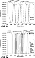
- the three sub-parts are structured such that they are interleaved between the right and left channels. From a practical standpoint, this means that the three sub-parts are arranged such that one filter has at least one sub- part lower and one sub-part higher than the sub-part of the other filter. For example, in Fig. 14 , the blue passbands of the right channel projection filter straddle the blue passband of the left channel projection filter. Such interleaving is preferably maintained in the various examples useful for understanding the present invention, including those examples that divide passbands into more than 3 sub-parts.
- Fig. 15 shows the color space diagrams for the filters of this example useful for understanding the present invention described above.
- the intersection, or product, of the left channel projection filter color space and right channel projection filter color space results in a color space more closely matching the color space 1200 ( Fig. 12 ) than which occurs with conventional spectral separation.
- Some portions of the color space are reduced and other portions of the color space are increased.
- some areas of the color space are reduced, the reduced areas are less important to viewers. Areas of the color space to which viewers are more sensitive have made significant gains with this example versus conventional spectral separation.
- the right eye lens of the glasses would have a filter with passband wavelengths of approximately 430 to 440 nm (part of the blue band), 484 to 528 nm (part of the blue, and part of the green band), 568 to 623 (part of the green band and the red band), which encompass the passbands of the right channel projector filter.
- the left eye lens of the glasses would have a filter with passband wavelengths of 455 to 471 (blue), 539 to 555nm (green), and 634 to 700 nm (red) which encompass the passbands of the left channel projector filter. Wavelengths below the beginning wavelengths in the blue (approximately 430 nm) and wavelengths above ending wavelengths in red (approximately 700 nm) are beyond the visible spectrum and may either be included or excluded from the passbands. Other permutations exist as described before (including left/right channel exchange), but the left and right eye lenses of the glasses include corresponding permutations that encompass or match the left and right channel projector filter permutations.
- the final images viewed through the glasses are a product of the projecting filters and viewing filters (e.g., filters in the glasses used to view the images).
- the receiving filters according to embodiments of the present invention are less demanding as far as passband design because they have fewer notches and they generally encompass more wavelengths in at least some of the passbands.
- the important role played by the glasses is separation of the entire images as whole and as projected, not specific bands within each image as described for the projection filters.
- the overall response (color space and white point) to the eye is the product of the spectral response of the projector filter(s), the lenses/filters of the eyeglasses, and the base D-Cinema projector response (color space and white point of the D-Cinema projector without the left and right channel projector filters). Nevertheless, the color space is mostly defined by the position of the passbands and the notches in the yellow and blue-green bands, and therefore the overall response is mostly a function of the projector filter (because the glasses do not need and preferably do not have the notches).
- the eyeglass filters are also comparatively less expensive to produce compared to the projection filters.
- the eyeglass filters are generally embodied as a pair of glasses worn by viewers (including the general public), and are therefore likely to be subjected to less than perfect care, whereas the projector equipment including the projector filters are generally kept in more secure and stable environments.
- the glasses are generally purchased in larger numbers than the projector filter(s).
- each viewing filter and its corresponding projection filter of the same channel are not symmetric in bandwidth and/or the number of passbands.
- the passbands of the viewing filters may also entirely encompass the passbands of the projection filters (and, in some embodiments, the passbands of the projector filter may be blue-shifted relative to the passbands of the viewing filters to account for viewing angle related blue shifts in the viewing filters).
- the passbands of the viewing and projection filters preferably are different. Therefore, a preferred result is an asymmetric filtering system.
- the particular projector filter response used in describing the invention uses 3 divisions of the blue and green projector color bands.
- the red band is divided into two parts (one part for the right channel and one part for the left channel). Additional divisions may be utilized for increased color space, but additional cost of the filters may be incurred.
- Careful selection of the optical passbands provides a close match to the color space and white point of the original unfiltered projector.
- the design of the glasses is such they have the same complexity of the conventional spectral separation design, but provide adequate selectivity to minimize crosstalk between the images projected in the left and right channels.
- Fig. 17A is a block diagram of a projection system 1700 according to an embodiment of the present invention.
- the projection system 1700 includes a digital cinema projector 1705 that projects spectrally separated 3D images (a left channel image and a right channel image) through projection filter 1730 and projection lens 1720 onto a screen 1710 for viewing with glasses 1715.
- Glasses 1715 include, for example spectrally separated filters disposed as coatings on each lens of the glasses such that the right lens comprises a filter that matches or encompasses the passbands of the right channel filter and the left lens comprises a filter that matches or encompasses passbands of the left channel filter (each of the left and right channel images are intended to be viewed by a viewer's corresponding left or right eye through the corresponding left or right eye lens/filter of the glasses).
- the glasses 1715, and system 1700 may, for example, include any of the features, systems, or devices described in Richards et al ., a U.S. Patent Application entitled METHOD AND SYSTEM FOR SHAPED GLASSES AND VIEWING 3D IMAGES, Serial No. 11/801,574, filed May 09, 2007 , the contents of which are incorporated herein by reference as if specifically set forth.
- the projector 1705 receives image data for projection from a server 1780.
- 3D content is provided to the server 1780 from, for example, a disk drive 1740.
- 3D content may be transmitted to projector 1705 over a secure link of network 1755 from, for example, an image warehouse or studio 1750.
- Multiple other projectors e.g., at theaters around the globe, 1760 1 ..1760 n
- the server 1780 includes color correction module 1775 that performs mathematical transformations of color to be reproduced by the projector prior to image projection.
- the mathematical transformations utilize image data for each of the left and right channels and transform them into parameters consistent with the primary colors or passbands of the corresponding left or right channel filter.
- the mathematical transformation, or color corrections adjust the hue of each image and maximize the available color space and match the color space and white point of projector 1705 as closely as possible.
- the amount of color correction required when using the invention is significantly reduced when compared with conventional spectral separation.
- the color corrected 3D content is transmitted to projector 1705.
- the 3D content includes left and right channel images that switch at a rate fast enough that they blend into a single 3D image when viewed by a viewer through glasses 1715.
- filters according to an example useful for understanding the present invention are utilized.
- a filter wheel 1730 is placed at point in the optical path closer to the light source.
- Fig. 17B provides an illustrative example of a filter wheel 1730 in front, side, and angle views.
- exemplary filter wheel 1730 includes, for example: an outside diameter (OD) 1732 of 125.00mm +/- 0.15mm, an inside hole 1734 with a diameter (ID) of 15.08mm +/- 0.04mm (that is, for example, off-center by not more than .075mm), and a thickness of 1.00mm - 1.20mm.
- OD outside diameter
- ID diameter
- ID thickness
- the exemplary filter wheel includes, for example, Material: Borofloat or Fused Silica, Monolithic Filter, 2 Section (e.g., TYPE A, a first channel filter, and TYPE B, a second channel filter), Max 3mm Undefined Transition, Clear Aperature: 1mm From OD, 10mm From ID, Surface Quality: 80-50 Where Scratch Number Is Width Measured In Microns, Edge Finish: As Fabricated, Edge Chips: Less Than Or Equal To 1 mm. All such specifications are exemplary and other combinations of materials, dimensions, and/or construction techniques, etc, may be utilized.
- an electronically switched filter 1725 is placed, for example, after the projection lens 1720.
- a controller 1735 provides signals that maintain synchronization between the filter 1730 and the image being projected.
- features of a left channel filter according to an example useful for understanding the present invention are active when a left channel image is being projected
- features of a right channel filter according to an example useful for understanding the present invention are active when a right channel image is being projected.
- the controller signals switching between left and right channel filters in synchronicity with the left and right image projections.
- the controller maintains a rotational speed and synchronicity between the left and right channel images and the left and right channel filters respectively.
- the blended image as viewed through glasses 1710 has a color space and white point that closely matches a color space and white point of projector 1705 without filter 1730.
- a filter wheel having left and right channel projection filters disposed thereon and which is placed inside a movie projector between the light source and integrating rod of the movie projector.
- the advantage of this placement is that the amount of light passing through the remaining optical components is reduced and less likely to overload sensitive electronics or other components (e.g. DLP, LCOS, or other light processors or light valves in the projector), but the amount of light that exits the projection is system is equivalent to examples where the projection filter(s) is placed further downstream locations.
- the power of the light source can be increased resulting in increased output without jeopardizing the integrating rod or other downstream components.
- the filter can be made smaller than at most other points in the light patch, and at a reduced cost compared to larger filters. And, images formed after filtering are generally found to be sharper than images formed and then filtered.
- the projection filter is a filter wheel where approximately 1 ⁇ 2 the wheel has filter characteristics of a left channel filter and approximately 1 ⁇ 2 the wheel has filter characteristics of a right channel filter.
- Table 1 specifies an exemplary filter wheel specification for a multi-band filter having a left channel filter section and right channel filter section.
- the Delta values shown in Table 1 specify a slope (steepness) of the band edges.
- the T50 values specify the wavelength at the band edge where the light transmission is 50%.
- the wheel may have, for example a diameter of approximately 125mm diameter which is well suited for installation in a D- Cinema projector (e.g., projector 705) between the light source and integrating rod.
- a D- Cinema projector e.g., projector 705
- Table 2 specifies an exemplary set of viewing filters matching (or encompassing the passbands of the projector filters but also including a small amount of red shift).
- the filters include a multi-band filter for the left channel (or left eye lens) and a multi-band filter for the right channel (or right eye lens).
- the Delta values specify the slope (steepness) of the band edges.
- the T50 values specify the wavelength at the band edge where the light transmission is 50%. At the band pass wavelengths the transmission is at least 90%, and at the band reject wavelengths the transmission is less than 0.5%.
- Fig. 18 is a drawing of a fixed filter arrangement in a two projector system 1800 according to an example useful for understanding the present invention.
- Left and right channel images are derived, decoded, retrieved, or reconstructed from data stored on disk drive 1840 (or received from an appropriate network or transmission reception) by server 1880. Color correction as described above may also be applied (not shown).
- the decoded, color corrected (if applicable), left and right channel images are then projected simultaneously from left and right channel projectors 1805A and 1805B onto screen 1810 for viewing through glasses 1715.
- a right channel filter 1820A having passband characteristics as described above is used to filter the projected right channel image.
- a left channel filter 1820B having passband characteristics as described above is used to filter the projected left channel image.
- the right and left channel filters are fixed filters (e.g., filters with characteristics that do not change with time), and are constructed, for example, from a clear substrate (e.g., glass) coated with appropriate layers to produce the passbands for the desired left or right channel filter characteristics.
- the fixed filter may be located in the projector at any point in the optical path, or may be located outside the projector past the projection lens as shown in Fig. 18 .
- division of sub-parts as described herein may be performed at any of the available wavelengths and can therefore be extended into the red wavelengths.
- discussion above should not be viewed to limit implementations of wherein the additional sub-parts of the blue and green bands are necessarily in the same channel, as these examples can be practiced by having two sub-parts of blue in a first channel, one sub- part of blue in a second channel, two sub-parts of green in the second channel, and one sub-part of green in the first channel. The same also logically extends to examples with more than three sub-parts where the additional subparts may be in any of the color bands and any of the channels.
- curved glass lenses having a 50mm radius of curvature is exemplary and any other radii could be utilized so long as the radius does not extend toward infinity (making the glasses flat, or essentially flat).
- a 40 mm radius or an 80 mm radius or more may provide suitable alternatives and not detract an unacceptable amount from the benefits of the described 50 mm radius of curvature.
- a radius of curvature of the glass lenses is 90mm (alternatively, approximately 90mm) which represents an acceptable trade-off considering the cost and difficulty of coating lenses with a greater amount of curvature without detracting too substantially from the benefits of optimally curved lenses.
- viewing glasses comprising a non-flat substrate (e.g., non-flat lenses), with spectrally complementary filters (alternatively, the filters are for two channels such that the filter of a first channel passes light bands of the first channel and blocks light bands of the second channel and visa- versa).
- the viewing glasses according to the present invention comprise a first lens having a first spectral filter, and a second lens having a second spectral filter spectrally complementary to the first spectral filter, and, in some embodiments, the first and second lenses are each curved to reduce a wavelength shift that occurs when viewing an image at other than a normal angle through the lens.
- the curve of each lens comprises, for example, any of: a radius centered on the viewers pupil, a radius centered behind the viewers pupil, a non-spherical shape, a cylindrical shape, includes multiple radii, a predetermined mathematical function, prescription curvatures.
- the spectral filters have a thickness that varies by location on the lens.
- the spectral filters according to the present invention comprise a plurality of dielectric layers, and the dielectric layers have an increased layer thickness toward edges of the lenses such as to red shift the filter characteristics at edges of the filters.
- the viewing filters comprise a non-flat substrate.
- At least one of the spectrally complementary filters comprises, for example, a single passband configured to pass two lightbands of different colors. In one embodiment, at least one of the spectrally complementary filters comprises a single passband configured to pass two different colors of light. In one embodiment, the spectrally complementary filters are configured for viewing a 3D display, which, for example, may comprise a reflection off a cinema screen. In one embodiment, the spectrally complementary filters comprise, for example, a first filter having a set of primary passbands comprising, a first passband configured to pass both a green lightband and a red lightband, and a second passband configured to pass both a blue lightband and a green lightband.
- the spectrally complementary filters comprise, a first filter comprising a first set of primary passbands comprising a passband configured to pass both a green lightband and a red lightband, and a second filter comprising a second set of primary passbands comprising a passband configured to pass both a blue lightband and a green lightband.
- the spectrally complementary filters comprise a first filter having a set of 3 passbands configured to pass a set of more than 3 primary color lightbands.
- the spectrally complementary filters comprise a first filter comprising a first set of passbands configured to pass a first set of primary lightbands and a second filter comprising a second set of passbands configured to pass a second set of primary lightbands, wherein the first set of primary lightbands are mutually exclusive to the second set of primary lightbands.
- the first set of passbands and the second set of passbands may be, for example, separated by guard bands having a width calculated to maintain separation between the primary lightbands when viewed through the viewing filters and compensate for blue shift due to a viewing angle of the primary lightbands through the viewing filters.
- at least one of the passbands encompasses at least two of the primary lightbands.
- spectral separation viewing glasses comprising, a first lens comprising a first spectral filter, and a second lens comprising a second spectral filter spectrally complementary to the first spectral filter, wherein the first spectral filter and the second spectral filter have at least one guard band between adjacent portions of spectrum of the spectral filters, and the guard band bandwidth is calculated based on an amount of blue shift occurring when viewing portions of the spectrally separated images at an angle through the lenses.
- the guard band has a bandwidth sufficient to reduce crosstalk of spectrally separated images viewed through the glasses.
- the guard band comprises, for example, approximately 2% or more of a wavelength of a crossover point of adjacent portions of the spectral filters.
- a spectral separation viewing system comprising, viewing glasses according to an embodiment of the present invention, comprising a first lens having a first spectral filter, and a second lens having a second spectral filter spectrally complementary to the first spectral filter, wherein the spectral filters include a guard band between adjacent portions of spectrum of the first and second lenses, and the lenses have a curvature configured to cause angles of incidence of light at edges of the lenses to be closer to normal when compared to flat lenses.
- the curvature of the lenses are, for example, spherical.
- the viewing system further comprises, for example, a projection system configured to project first and second spectrally separated images, and the first and second spectrally separated images are each respectively viewed through the spectral filters of the viewing glasses according to an embodiment of the present invention.
- the viewing system may also further comprise, for example, a plurality of pairs of said viewing glasses, each pair of viewing glasses being assigned to an individual viewer in a movie theater audience, and the first and second filters are disposed on lenses of each pair of glasses.
- a method comprising the steps of, projecting first and second spectrally separated images onto a display screen, viewing the projected images through a pair of glasses according to an embodiment of the present invention, having a first lens having a first spectral filter designed to be used with the first spectrally separated image and a second lens having a second spectral filter designed to be used with the second spectrally separated image, and wherein the spectral filters are configured to have an amount of wavelength shift effect depending upon a viewing angle through the lens.
- adjacent portions of spectrum of the first and second spectral filters are separated by a guard band comprising a bandwidth calculated for a central viewing location and sufficient to eliminate crosstalk for normal viewing from edges of the display screen.
- the spectral filters comprise a plurality of guard bands each separating a different set of adjacent spectrums in the first and second filters, and a bandwidth of each guard band is determined based on a function of a crossover wavelength of the adjacent spectrums and a viewing angle to an edge of the display screen.
- the display screen is, for example, a cinema movie screen.
- a 3D viewing system comprising means for projecting spectrally separated images, means, according to the present invention, for viewing the spectrally separated images through different ocular channels, and means, according to the present invention, for compensating for wavelength shifts occurring due to viewing angles to portions of the images.
- the means for compensating includes, for example, means for adjusting an amount of spectral filtering performed based on viewing angle.
- the means for compensating includes, for example, means for producing a wavelength mismatch between projector filters used to project the spectrally separated images and eye filters used to view the spectrally separated images, wherein the mismatch compensates for an amount of wavelength shift that occurs in the eye filters due to light incident upon the eye filters at non-normal angles.
- a viewing system comprising shaped glasses according to an embodiment of the present invention, comprising a pair of left and right spectrally complementary filters respectively disposed on left and right curved lenses of the glasses, and a display system configured to display spectrally separated left and right images respectively configured to be viewed through the left and right complementary filters, wherein each spectrally separated image comprises at least one light bandwidth approximately matching at least one pass band of its corresponding filter.
- the display system further comprises, for example, a projector configured to display the spectrally separated left and right images with a pre-determined amount of pre-blue shift.
- the spectrally complementary filters comprise guard bands between adjacent spectrums of the spectrally complementary filters.
- the shaped glasses of the viewing system are, for example, utilized to view color shifted projections of spectrally complementary images.
- the shaped glasses of the viewing system include frame temples and a bridge designed to flex implementing an adjustable dihedral angle between the lenses.
- An amount of the dihedral angle change due to flexing is, for example, approximately 5 degrees.
- a method comprising the steps of, distributing shaped glasses according to an embodiment of the present invention to audience members; and projecting first and second spectrally complementary images on a display screen within view of the audience members, wherein the shaped glasses comprise first and second shaped lenses having first and second spectrally complementary filters respectively disposed thereon, and the first and second spectrally complementary filters respectively correspond in bandwidth to the projected first and second spectrally complementary images.
- the bandwidth correspondence of the first spectrally complimentary filter passes colors in a first channel of a projection and blocks colors in a second channel of the projection
- the bandwidth correspondence of the second spectrally complimentary filter passes colors in a second channel of a projection and blocks colors in a first channel of the projection
- a storage medium having a visual performance stored thereon, that, when loaded into a media player coupled to a display device, causes the media player to transmit the visual performance for display to the display device, wherein the visual performance comprises spectrally separated images configured to be viewed respectively through independent ocular channels using curved spectrally separated filters according to an embodiment of the present invention.
- the storage medium is, for example, prepackaged with at least one pair of glasses having curved lenses upon which the curved spectrally separated filters are disposed.
- the spectrally separated images are, for example, displayed by the display device using filters that are blue shifted compared to filtering that occurs through normal angle viewing of the curved spectrally separated filters.
- the spectrally separated images are, for example, separated by a guard band configured to compensate for spectra mismatch between the projected images and properties of filters used to view the projected images.
- the combination of pre-blue shifting, curved lenses, and guard bands effectively eliminates crosstalk when viewing the images.
- a system for viewing 3D images, comprising, serving 3D content over a network to a receiving electronic device, projecting the 3D content to a display device, wherein the 3D content comprises spectrally complementary images intended to be viewed with shaped glasses.
- the receiving electronic device comprises, for example, a display system located at a movie theater.
- the projected 3D content is projected with a predetermined amount of blue-shift.
- a method of displaying an 3-D image comprising the steps of, projecting left and right filtered images onto a screen, and filtering the left and right images for each of spectrally specific properties corresponding to the image prior to display on the screen, wherein the filtering is performed with a filter having characteristics that are shifted an amount configured to compensate for a wavelength shift that occurs when a viewer watches the screen.
- the wavelength shift comprises, for example, a blue-shift that occurs due to viewing angles (which may be, for example, a blue-shift that occurs in characteristics of an eye filter used to view the images, or, as another example, a blue-shift occurring in filtered viewing glasses according to an embodiment of the present invention when viewing any of the images through the filtered viewing glasses at other than a normal angle).
- the spectrally specific properties corresponding to the image comprise, for example, a set of wavelengths corresponding to the right images and a complementary set of wavelengths corresponding to the left images.
- a projector filter comprising, a first filter having a first set of primary passbands, and a second filter having a second set of primary passbands, wherein the first set of primary passbands has a different number of primary passbands than the second filter.
- the first filter has, for example, at least two blue primary passbands and the second filter has at least one blue primary passband.
- the first filter has, for example, at least two green primary passbands and the second filter has at least one green primary.
- the first filter has, for example, two blue primaries and two green primaries and the second filter has one blue primary and one green primary.
- the first filter has, for example, passband wavelengths of approximately 400 to 440 nm and 484 to 498 nm, 514 to 528 nm, 567 to 581 nm, and 610 to 623 nm.
- the second filter has, for example, passband wavelengths of approximately 455 to 471 nm, 539 to 556 nm, and 634 to 700 nm.
- the passband wavelength specifications have a tolerance of, for example, approximately ⁇ 5 nm.
- the primary passbands of the first filter excludes wavelengths passed by the second filter.
- the primary passbands of the filters are selected to maximize reproduction of a color space of a projector.
- the projector color space is, for example, the color space of a D-Cinema projector.
- the projector filter is an electronically switchable filter that switches between the first and second filters according to an image synchronization signal.
- a system for projection of spectrally separated 3D images comprising, a projection system configured to project left and right channel images for display by a viewer, a filter placed in at least one light path of the projection system comprising a left channel filter and a right channel filter, wherein at least one of the left and right channel filters has more than 3 primary passbands.
- one of the left and right channel filters has at least 2 primary passbands in blue wavelengths.
- one of the left and right channel filters has at least 2 primary passbands in green wavelengths.
- one of the left and right eye channel filters has at least 2 primary passbands in blue wavelengths and at least 2 primary passbands in green wavelengths.
- the primary passbands of the filters are selected to maximize reproduction of a color space of the projection system in images projected by the projection system.
- the system further comprises a color correction module configured to color correct images projected by the projection system according to a color space of the filters.
- the color correction module is configured to color correct images based on a color space of light passed by the filter.
- a pair of projector spectral separation filters are provided and configured to divide a blue projector primary into three sub- parts, a green projector primary into three sub-parts, and a red projector primary into to two sub-parts.
- One of the filters has, for example, two passbands in blue, two passbands in green, and a single passband in red, and the other filter has one passband in blue, one passband in green, and one passband in red.
- one of the filters has, for example, two passbands in blue, two passbands in green, and only one passband in red, and the other filter has only one passband in blue, only one passband in green, and only one passband in red.
- one of the filters has, for example, two passbands in blue, one passband in green, and one passband in red, and the other filter has one passband in blue, two passbands in green, and one passband in red.
- one of the filters has, for example, two passbands in blue, only one passband in green, and only one passband in red, and the other filter has only one passband in blue, two passbands in green, and only one passband in red.
- one of the filters has one passband in blue, two passbands in green, and one passband in red, and the other filter has two passbands in blue, one passband in green, and one passband in red.
- one of the filters has only one passband in blue, two passbands in green, and only one passband in red, and the other filter has two passbands in blue, only one passband in green, and only one passband in red.
- the sub-part passbands are located to achieve a substantial match to an original color space and white point of an unfiltered D-Cinema projector.
- a set of color filters comprising, a first filter having a first set of primary color passbands, a second filter having a second set of primary color passbands of different wavelengths compared to the first set of primary colors, wherein the first filter has more than one primary color in at least one color band.
- the filter set is embodied, for example, as an electronically switchable filter set.
- the color filter set is part of a 3D projection system and the primary passbands of the first and second filters are selected to maximize reproduction of a color space of the 3D projection system without the first and second filters.
- a method comprising the steps of, preparing a 3D image comprising a left image and a right image, filtering the left image with a left channel filter, filtering the right image with a right channel filter, and projecting the left and right filtered images onto a screen, wherein at least one of the left channel filter and right channel filter have more than 3 primary passbands.
- One of the left and right channel filters comprises, for example, 2 primary passbands in blue wavelengths and 2 primary passbands in green wavelengths.
- the method further comprises, for example, a step of viewing the projected 3-D image through left and right viewing filters according to an embodiment of the present invention having passbands that respectively exclude passbands of the right channel filter and the left channel filter.
- the method further comprises, for example, a step of switching the left and right channel filters in synchronicity with the projection of left and right channel images of the 3D image.
- a 3D viewing system comprising a first asymmetric filter set comprising a projection filter and a viewing filter according to an embodiment of the present invention.
- the 3D viewing system may further comprise, for example, a second asymmetric filter set wherein the first asymmetric filter set is positioned in an optical path of the system and configured to pass wavelengths of a first channel of the system and the second filter set is configured to pass wavelengths of a second channel of the system.
- the viewing filter includes passbands that encompass passbands of the projection filter.
- the viewing filter includes, for example, passbands that approximately encompass passbands of the projection filter; and the passbands of the projection filter are blue-shifted compared to the passbands of the viewing filter.
- an asymmetric filter system comprising, a first set of filters comprising a first set of optical passbands, a second set of filters comprising a second set of optical passbands different from the first set of optical passbands and encompassing the first set of optical passbands.
- the first set of filters is upstream in an optical path relative to the second set of filters.
- the first set of filters comprise a projection filter and the second set of filters comprise a viewing filter according to an embodiment of the present invention.
- the first set of optical passbands comprises a right channel set of optical passbands and a left channel set of optical passbands that exclude any portion of the right channel set of optical passbands.
- the second set of optical passbands include a left channel set of optical passbands and a right channel set of optical passbands that exclude any portion of the left channel optical passbands.
- a method comprising the steps of, providing a theater audience with a pair of 3D viewing glasses according to an embodiment of the present invention and comprising left and right lenses respectively comprising left and right viewing filters, and projecting left and right images onto a display screen using left and right projection filters, wherein the left projection filter and the left viewing filter comprise a first asymmetric filter set and the right projection filter and the right viewing filter comprise a second asymmetric filter set.
- a total number of passbands in the viewing filters is less than a total number of passbands in the projection filters.
- the projector filters comprise passbands that divide blue light wavelengths into at least three blue sub-parts and that divide green wavelengths into at least two green sub-parts.
- a viewing filter in one of the asymmetric filter sets comprises a passband that encompasses wavelengths in the longest wavelength blue sub-part and wavelengths in a green sub-part.
- the projector filters comprise passbands that divide green light wavelengths into at least three sub-parts and divide red light into at least two red sub-parts, and a viewing filter in one of the asymmetric filter sets comprises a passband that encompasses a longest wavelength green sub-part and a red sub-part.
- the projector filters comprise passbands that divide blue light wavelengths into at least three sub-parts and green light wavelengths into at least three sub-parts, and a viewing filter in one of the asymmetric filter sets comprises a passband that encompasses a longest wavelength blue sub-part and a shortest wavelength green sub-part.
- the projector filters comprise passbands that divide green light wavelengths into at least three sub-parts and red light wavelengths into at least three sub-parts, and a viewing filter in one of the asymmetric filter sets comprises a passband that encompasses a longest wavelength green sub-part and a shortest wavelength red sub- part.
- each viewing filter comprises, three passbands exclusively comprising one passband including blue wavelengths, one passband including green wavelengths, and one passband including red wavelengths.
- the projector filters comprise 3 passbands each in green and blue light wavelengths and two passbands in red wavelengths.
- the viewing filters each exclusively comprises three passbands, one passband of blue wavelengths, one passband of green wavelengths, and one passband of red wavelengths.
- a filter is provided that is configurable in an eyewear device of a spectrally separated 3D viewing system, comprising a set of passbands and blocking bands configured to pass light wherein at least one of the passbands is capable of passing bands of 2 different colors of light and the blocking bands are configured to block light in at least one band of light in each of the 2 different colors.
- the passband capable of passing bands of 2 different colors of light does not pass light in a third color.
- the bands of 2 different colors of light are separated by a notch.
- the notch is, for example, a band (a notch band) not utilized by the 3D viewing system for light transmission.
- the notch band is, for example, relatively narrow compared to the bands of 2 different colors of light.
- the notch band bandwidth is similar to a bandwidth of at least one of the bands of 2 different colors of light.
- the notch band encompasses a transition from wavelengths of a first of the 2 different colors of light to wavelengths of a second of the two different colors of light.
- the 2 different colors of light comprise blue light and green light and the third color comprises red.
- the 2 different colors of light comprise red light and green light and the third color comprises blue.
- the filter is disposed on a curved substrate.
- the filter is disposed on a curved substrate having a radius of approximately 90mm.
- the filter is disposed on a curved lens having a radius of approximately 40mm to 200mm.
- a filter comprising only 3 mutually exclusive passbands of visible light, a first passband configured to pass only a first color of light, a second passband configured to pass 2 spectrum adjacent colors of light comprising the first color of light and a second color of light, and a third passband configured to pass 2 spectrum adjacent colors of light comprising the second color of light and a third color of light.
- the first second and third colors of light are, for example, blue, green, and red, respectively.
- the first, second, and third colors of light are red, green, and blue, respectively.
- the filter is, for example, disposed on a lens configurable as a channel filter in a pair of 3D viewing glasses.
- any other equivalent device or device having an equivalent function or capability, whether or not listed herein, may be substituted therewith.
- any other material used as filter and exhibiting a substantive wavelength shift e.g., nano-material coatings
- a flexible bridge piece may be substituted with any mechanism suitable to adjust a dihedral angle of the lens, including a ratchet mechanism, spring loaded stops, etc.
- lenses according to the present invention may be constructed of glass, plastic, or any other such material providing the appropriate shapes as described above.
- the present invention may suitably comprise, consist of, or consist essentially of, any of element (the various parts or features of the invention) and their equivalents as described herein. Further, the present invention illustratively disclosed herein may be practiced in the absence of any element, whether or not specifically disclosed herein. Obviously, numerous modifications and variations of the present invention are possible in light of the above teachings. It is therefore to be understood that within the scope of the appended claims, the invention may be practiced otherwise than as specifically described herein.
- the disclosed examples may include a computer program product which is a storage medium (media) that includes, but is not limited to, any type of disk including floppy disks, mini disks (MD's), optical discs, DVD, HD-DVD, Blue-ray, CD-ROMS, micro- drive, and magneto-optical disks, ROMs, RAMs, EPROMs, EEPROMs, DRAMs, VRAMs, flash memory devices (including flash cards, memory sticks), magnetic or optical cards, SIM cards, MEMS, nanosystems (including molecular memory ICs), RAID devices, remote data storage/archive/warehousing, or any type of media or device suitable for storing instructions and/or data.
- the disclosed examples may include software for controlling aspects of the present disclosure including, for example, switching of pre-blue shifted filters or performance of color correction stored on any computer readable medium (media).
- such media may include or exclusively contain content prepared or ready for display according to the present invention.
- content is, for example, read from the media and then transmitted electronically over a network, broadcast over the air, or transmitted by wire, cable or any other mechanism.
- the content of such media may be provided to a display device and then viewed in accordance with one or more aspects of the invention.
- the content is, for example, prepared or optimized so as to project images having bandwidths optimized for the display and viewing processes described herein.
- Such media may also be packaged with glasses and/or filters prepared according to one or more of the various aspects of the invention as described above.
- the present invention may suitably comprise, consist of, or consist essentially of, any of element (the various parts or features of the invention, e.g., shaped lenses, varying dielectric layer thicknesses, etc., and/or any equivalents. Further, the present invention illustratively disclosed herein may be practiced in the absence of any element, whether or not specifically disclosed herein. Obviously, numerous modifications and variations of the present invention are possible in light of the above teachings. It is therefore to be understood that within the scope of the appended claims, the invention may be practiced otherwise than as specifically described herein.
- the viewing filters according to EE1-EE10 are utilized in 3D viewing glasses according to embodiments of the present invention.
- the filters according to EE11-EE12 are utilized in in 3D viewing glasses according to embodiments of the present invention.
- the viewing filters according to EE1 wherein the non-flat substrate comprises a curved surface configured to reduce a wavelength shift that occurs when viewing an image at other than a normal angle through the filters.
- EE5 The viewing filters according to EE1, wherein the non-flat substrate includes at least one prescription curvature.
- the viewing filters according to EE1 wherein at least one of the spectrally complimentary filters comprises a single passband configured to pass two different colors of light.
- EE7 The viewing filters according to EE6, wherein the spectrally complimentary filters are configured for viewing a 3D display.
- the viewing filters according to EE1 wherein the spectrally complimentary filters comprise a first filter having a set of 3 passbands configured to pass a set of more than 3 primary color lightbands.
- a filter comprising three mutually exclusive passbands of visible light, a first passband configured to pass only a first color of light, a second passband configured to pass two spectrum adjacent colors of light comprising the first color of light and a second color of light, and a third passband configured to pass two spectrum adjacent colors of light comprising the second color of light and a third color of light.
- a viewing system comprising:
- the at least one light band absent from at least one of the spectrally separated images is a light band between at least one of blue and green light bands and green and red light bands.
- EE16 The system according to EE13, wherein the display system comprises a projector configured to display the spectrally separated left and right images with a predetermined amount of pre-blue shift.
- a 3D viewing system comprising a first asymmetric filter set comprising a projection filter and a viewing filter.
- the 3D viewing system according to EE17 further comprising a second asymmetric filter set wherein the first asymmetric filter set is positioned in an optical path of the system and configured to pass wavelengths of a first channel of the system and the second filter set is configured to pass wavelengths of a second channel of the system.
- EE21 The 3D viewing system according to EE17, wherein the viewing filter includes passbands that approximately encompass passbands of the projection filter; and the passbands of the projection filter are pre-blue-shifted compared to the passbands of the viewing filter.
- EE22 The 3D viewing system according to EE17, wherein the projection filter comprises at least one channel configured to pass multiple primary passbands for a same color light.
- EE23 The 3D viewing system according to EE17, wherein the projection filter comprises at least one channel comprising at least two passbands of light in adjacent colors.
- EE24 The 3D viewing system according to EE23, wherein the passbands of light in adjacent colors are separated by a blocking notch.
- the viewing filters comprise passband channels approximately encompassing the passbands of the projector filter including the blocking notch such that if the blocking notch were not present light passing the projection filter in the wavelengths of the blocking notch would also pass through the viewing glasses.
- a filter system comprising:
- the filter system according to EE26 further comprising a set of viewing filters including a first channel viewing filter and a second channel viewing filter, wherein the viewing filter corresponding to the channel of the notchband passes light wavelengths corresponding to the notchband.
- EE28 The filter system according to EE26, wherein the projection filter is disposed on a disk configured to be installed in a D-Cinema projector, and the at least one notchband comprises one of a blue-green notchband and a green-red notchband.
- EE29 The filter system according to EE26, wherein the at least one notchband comprises at least two notchbands comprising a blue-green notchband and a green-red notchband.
- EE30 The filter system according to EE29, wherein at least two of the notchbands are in the same channel.
- EE31 The filter system according to EE29, wherein at least one of the notchbands is in each channel.
- EE34 The filter system according to EE26, wherein the second channel passbands comprise wavelengths of approximately 455 to 471 nm, 539 to 556 nm, and 634 to 700 nm.
Landscapes
- Physics & Mathematics (AREA)
- General Physics & Mathematics (AREA)
- Optics & Photonics (AREA)
- Engineering & Computer Science (AREA)
- Multimedia (AREA)
- Signal Processing (AREA)
- Spectroscopy & Molecular Physics (AREA)
- Astronomy & Astrophysics (AREA)
- Ophthalmology & Optometry (AREA)
- Health & Medical Sciences (AREA)
- General Health & Medical Sciences (AREA)
- Stereoscopic And Panoramic Photography (AREA)
- Testing, Inspecting, Measuring Of Stereoscopic Televisions And Televisions (AREA)
- Measurement Of The Respiration, Hearing Ability, Form, And Blood Characteristics Of Living Organisms (AREA)
- Apparatus For Radiation Diagnosis (AREA)
- Projection Apparatus (AREA)
- Devices For Indicating Variable Information By Combining Individual Elements (AREA)
- Optical Filters (AREA)
- Eyeglasses (AREA)
- Radio Relay Systems (AREA)
Claims (13)
- Lunettes de visualisation 3D, comprenant un filtre de séparation spectrale de canal droit et un filtre de séparation spectrale de canal gauche, les filtres étant spectralement complémentaires l'un par rapport à l'autre et comprenant une pluralité de couches diélectriques ayant une épaisseur de couche augmentée vers des bords des filtres de manière à décaler vers le rouge les caractéristiques de filtre au niveau des bords des filtres.
- Lunettes de visualisation 3D selon la revendication 1, dans lesquelles le décalage vers le rouge est utilisé pour compenser un décalage vers le bleu provoqué par un changement d'angle au niveau des bords du champ de vision à travers les filtres.
- Lunettes de visualisation 3D selon la revendication 1 ou la revendication 2, dans lesquelles chacun des filtres est enrobé sur une surface incurvée.
- Lunettes de visualisation 3D selon la revendication 3, dans lesquelles la surface incurvée comprend un rayon d'approximativement 40 mm-200 mm.
- Lunettes de visualisation 3D selon l'une quelconque des revendications 1 à 3, dans lesquelles les lunettes comprennent un cadre qui maintient les lunettes à un angle dièdre, et dans lesquelles un pont du cadre fléchit en fonction d'une taille de tête d'un utilisateur pour régler automatiquement l'angle dièdre.
- Lunettes de visualisation 3D selon la revendication 5, dans lesquelles une taille de tête de l'utilisateur plus petite conduit à un angle dièdre plus petit et une taille de tête de l'utilisateur plus grande conduit à un angle dièdre plus grand.
- Lunettes de visualisation 3D selon l'une quelconque des revendications 1 à 6, dans lesquelles des bandes de garde entre le filtre de séparation spectrale de canal droit et le filtre de séparation spectrale de canal gauche sont supérieures à approximativement 2 % d'une longueur d'onde de croisement gauche/droite.
- Lunettes de visualisation 3D selon l'une quelconque des revendications 1 à 7, dans lesquelles un premier filtre parmi les filtres comprend un premier passe-bande qui varie d'en-dessous d'approximativement 430 nm à approximativement 442 nm, un second passe-bande qui varie d'approximativement 486 nm à approximativement 528 nm, et un troisième passe-bande qui varie d'approximativement 571 nm à approximativement 624 nm.
- Lunettes de visualisation 3D selon l'une quelconque des revendications 1 à 8, dans lesquelles un second filtre parmi les filtres comprend un premier passe-bande qui varie d'approximativement 458 nm à approximativement 472 nm, un seconde passe-bande qui varie d'approximativement 540 nm à approximativement 557 nm, et une région de transmission supplémentaire qui varie d'approximativement 637 nm à au-dessus d'approximativement 700 nm.
- Lunettes de visualisation 3D selon l'une quelconque des revendications 1 à 9, dans lesquelles les lunettes comprennent un cadre souple et/ou un cadre en plastique.
- Utilisation des lunettes de visualisation 3D selon l'une quelconque des revendications 1 à 10 pour visualiser des images spectralement distinctes, au moins l'une des images spectralement distinctes étant produite à l'aide de 5 bandes de longueurs d'onde de lumière.
- Utilisation selon la revendication 11, dans laquelle les filtres de séparation spectrale comprennent des passe-bandes qui sont décalés vers le rouge comparés à des bandes de longueurs d'onde correspondantes dans au moins l'une des images spectralement distinctes à visualiser.
- Utilisation selon la revendication 11 ou la revendication 12, dans laquelle au moins une longueur d'onde de coupure d'un passe-bande dans les filtres de séparation spectrale est décalée vers le rouge comparée à une longueur d'onde correspondante dans au moins l'une des images spectralement distinctes à visualiser.
Priority Applications (7)
| Application Number | Priority Date | Filing Date | Title |
|---|---|---|---|
| EP18188109.5A EP3442224B1 (fr) | 2007-05-09 | 2008-05-09 | Système pour des projections et une visualisation d'image en 3d |
| PL12154214T PL2485499T3 (pl) | 2007-05-09 | 2008-05-09 | System do projekcji i oglądania obrazu 3d |
| DK12154214.6T DK2485499T3 (da) | 2007-05-09 | 2008-05-09 | System til 3D-billedprojektioner og -betragtning |
| SI200832018T SI2280552T1 (sl) | 2007-05-09 | 2008-05-09 | Sistem za tridimenzionalno projiciranje in gledanje slik |
| EP12154214.6A EP2485499B1 (fr) | 2007-05-09 | 2008-05-09 | Système pour la projection et la visualisation d'images en 3D |
| PL10188344T PL2280552T3 (pl) | 2007-05-09 | 2008-05-09 | System do projekcji i oglądania obrazu 3D |
| HRP20181905TT HRP20181905T1 (hr) | 2007-05-09 | 2018-11-15 | Sustav za projiciranje i gledanje 3d slike |
Applications Claiming Priority (5)
| Application Number | Priority Date | Filing Date | Title |
|---|---|---|---|
| US11/801,574 US7784938B2 (en) | 2007-05-09 | 2007-05-09 | Method and system for shaped glasses and viewing 3D images |
| US11/804,602 US7959295B2 (en) | 2007-05-18 | 2007-05-18 | Spectral separation filters for 3D stereoscopic D-cinema presentation |
| US93132007P | 2007-05-21 | 2007-05-21 | |
| PCT/US2008/006007 WO2008140787A2 (fr) | 2007-05-09 | 2008-05-09 | Système pour des projections et une visualisation d'image en 3d |
| EP08754336A EP2145485B1 (fr) | 2007-05-09 | 2008-05-09 | Système pour des projections et une visualisation d'image en 3d |
Related Parent Applications (2)
| Application Number | Title | Priority Date | Filing Date |
|---|---|---|---|
| EP08754336.9 Division | 2008-05-09 | ||
| EP08754336A Division EP2145485B1 (fr) | 2007-05-09 | 2008-05-09 | Système pour des projections et une visualisation d'image en 3d |
Related Child Applications (4)
| Application Number | Title | Priority Date | Filing Date |
|---|---|---|---|
| EP12154214.6A Division-Into EP2485499B1 (fr) | 2007-05-09 | 2008-05-09 | Système pour la projection et la visualisation d'images en 3D |
| EP12154214.6A Division EP2485499B1 (fr) | 2007-05-09 | 2008-05-09 | Système pour la projection et la visualisation d'images en 3D |
| EP18188109.5A Division EP3442224B1 (fr) | 2007-05-09 | 2008-05-09 | Système pour des projections et une visualisation d'image en 3d |
| EP18188109.5A Division-Into EP3442224B1 (fr) | 2007-05-09 | 2008-05-09 | Système pour des projections et une visualisation d'image en 3d |
Publications (3)
| Publication Number | Publication Date |
|---|---|
| EP2280552A2 EP2280552A2 (fr) | 2011-02-02 |
| EP2280552A3 EP2280552A3 (fr) | 2011-05-18 |
| EP2280552B1 true EP2280552B1 (fr) | 2018-09-12 |
Family
ID=39684445
Family Applications (4)
| Application Number | Title | Priority Date | Filing Date |
|---|---|---|---|
| EP10188344.5A Active EP2280552B1 (fr) | 2007-05-09 | 2008-05-09 | Système pour projections et visualisation d'images en 3D |
| EP12154214.6A Active EP2485499B1 (fr) | 2007-05-09 | 2008-05-09 | Système pour la projection et la visualisation d'images en 3D |
| EP08754336A Active EP2145485B1 (fr) | 2007-05-09 | 2008-05-09 | Système pour des projections et une visualisation d'image en 3d |
| EP18188109.5A Active EP3442224B1 (fr) | 2007-05-09 | 2008-05-09 | Système pour des projections et une visualisation d'image en 3d |
Family Applications After (3)
| Application Number | Title | Priority Date | Filing Date |
|---|---|---|---|
| EP12154214.6A Active EP2485499B1 (fr) | 2007-05-09 | 2008-05-09 | Système pour la projection et la visualisation d'images en 3D |
| EP08754336A Active EP2145485B1 (fr) | 2007-05-09 | 2008-05-09 | Système pour des projections et une visualisation d'image en 3d |
| EP18188109.5A Active EP3442224B1 (fr) | 2007-05-09 | 2008-05-09 | Système pour des projections et une visualisation d'image en 3d |
Country Status (23)
| Country | Link |
|---|---|
| US (6) | US20100060857A1 (fr) |
| EP (4) | EP2280552B1 (fr) |
| JP (6) | JP5095761B2 (fr) |
| KR (12) | KR101798368B1 (fr) |
| CN (3) | CN102998802B (fr) |
| AT (1) | ATE492990T1 (fr) |
| AU (1) | AU2008251795A1 (fr) |
| BR (1) | BRPI0809408B1 (fr) |
| CA (1) | CA2680350C (fr) |
| DE (1) | DE602008004133D1 (fr) |
| DK (3) | DK2280552T3 (fr) |
| ES (2) | ES2698386T3 (fr) |
| HR (1) | HRP20181905T1 (fr) |
| HU (2) | HUE056057T2 (fr) |
| IL (4) | IL200700A (fr) |
| MX (1) | MX2009009993A (fr) |
| MY (5) | MY177295A (fr) |
| PL (3) | PL2145485T3 (fr) |
| PT (1) | PT2280552T (fr) |
| RU (2) | RU2584329C2 (fr) |
| SI (1) | SI2280552T1 (fr) |
| TW (3) | TWI402606B (fr) |
| WO (1) | WO2008140787A2 (fr) |
Families Citing this family (101)
| Publication number | Priority date | Publication date | Assignee | Title |
|---|---|---|---|---|
| TWI402606B (zh) * | 2007-05-09 | 2013-07-21 | Dolby Lab Licensing Corp | 三維影像之投影與觀看系統 |
| US7784938B2 (en) * | 2007-05-09 | 2010-08-31 | Dolby Laboratories Licensing Corporation | Method and system for shaped glasses and viewing 3D images |
| US7959295B2 (en) * | 2007-05-18 | 2011-06-14 | Dolby Laboratories Licensing Corporation | Spectral separation filters for 3D stereoscopic D-cinema presentation |
| KR101597375B1 (ko) | 2007-12-21 | 2016-02-24 | 디티에스 엘엘씨 | 오디오 신호의 인지된 음량을 조절하기 위한 시스템 |
| US20090316114A1 (en) * | 2008-06-18 | 2009-12-24 | Dolby Laboratories Licensing Corporation | Method and apparatus for light recapture and sequential channel illumination |
| US8411137B2 (en) * | 2008-07-16 | 2013-04-02 | Dolby Laboratories Licensing Corporation | Dual projection system with inversely synchronized channel projections |
| US8596794B2 (en) * | 2008-09-25 | 2013-12-03 | Dolby Laboratories Licensing Corporation | Projection system and projection system with light recycling |
| JP5532588B2 (ja) * | 2008-11-18 | 2014-06-25 | ソニー株式会社 | 画像表示装置および画像表示方法 |
| US20100208342A1 (en) * | 2009-02-19 | 2010-08-19 | Projectiondesign As | Methods and systems for creating passive stereo 3d images |
| US8538042B2 (en) | 2009-08-11 | 2013-09-17 | Dts Llc | System for increasing perceived loudness of speakers |
| KR20120051065A (ko) * | 2009-09-11 | 2012-05-21 | 톰슨 라이센싱 | 3차원(3d) 투영을 위한 방법 및 시스템 |
| EP2494786B1 (fr) | 2009-10-28 | 2018-07-25 | Dolby Laboratories Licensing Corporation | Dispositif d'affichage stereoscopique à double modulateur utilisant des anaglyphes muli-couleurs |
| US20110102563A1 (en) * | 2009-11-03 | 2011-05-05 | Johnson Jr Robert L | Multi-spectral stereographic display system |
| US20110102562A1 (en) * | 2009-11-03 | 2011-05-05 | PV Omega, LLC | Multi-spectral stereographic display system with additive and subtractive techniques |
| CN102141685B (zh) * | 2009-11-29 | 2016-02-24 | 黄得锋 | 一种3d成像装置 |
| KR101632340B1 (ko) * | 2010-01-11 | 2016-06-22 | 삼성디스플레이 주식회사 | 영상 표시 방법 및 이를 수행하기 위한 표시 장치 |
| JP2013525955A (ja) | 2010-04-16 | 2013-06-20 | フレックス ライティング 2,エルエルシー | フィルムベースのライトガイドを備える照明デバイス |
| TWI424785B (zh) * | 2010-05-05 | 2014-01-21 | Au Optronics Corp | 立體顯示器 |
| TWI419012B (zh) * | 2010-06-02 | 2013-12-11 | Univ Chaoyang Technology | A method of positioning an optical beacon device for interaction of a large display device |
| CN102279467A (zh) * | 2010-06-13 | 2011-12-14 | 陈小军 | 3d成像系统和方法 |
| US9053562B1 (en) | 2010-06-24 | 2015-06-09 | Gregory S. Rabin | Two dimensional to three dimensional moving image converter |
| CN102959966B (zh) | 2010-06-28 | 2016-06-15 | 杜比实验室特许公司 | 用于立体显示的背光单元 |
| CN102959455B (zh) * | 2010-06-28 | 2016-06-29 | 辛维特有限公司 | 3d立体显示器的观看辅助设备 |
| JP2012049604A (ja) * | 2010-08-24 | 2012-03-08 | Sony Corp | エミッタ装置、立体映像表示装置及びコマンド送出方法 |
| JP5609566B2 (ja) * | 2010-11-10 | 2014-10-22 | 船井電機株式会社 | プロジェクタ |
| US20130162952A1 (en) * | 2010-12-07 | 2013-06-27 | Laser Light Engines, Inc. | Multiple Laser Projection System |
| KR101729759B1 (ko) * | 2010-12-10 | 2017-04-25 | 삼성디스플레이 주식회사 | 입체 영상 표시 방법 및 이를 수행하는 표시 장치 |
| CN102572456B (zh) * | 2010-12-22 | 2014-11-26 | 深圳Tcl新技术有限公司 | 一种眼镜式立体显示装置的色彩修正方法 |
| AU2012223124B2 (en) | 2011-03-03 | 2015-11-05 | Enchroma, Inc. | Multi-band color vision filters and method by LP-optimization |
| DE102011005136B4 (de) | 2011-03-04 | 2012-10-04 | Infitec Gmbh | Brille zum Betrachten stereoskopischer Bilder oder eines Perspektivteilbildes eines solchen |
| US9766479B2 (en) | 2011-03-05 | 2017-09-19 | Dolby Laboratories Licensing Corporation | Eyeglasses for personal and commercial use including reuse in 3D theater and other repeated operations |
| US9696558B2 (en) * | 2011-03-14 | 2017-07-04 | Dolby Laboratories Licensing Corporation | 3D projection system using laser light sources |
| ES2924254T3 (es) | 2011-03-14 | 2022-10-05 | Dolby Laboratories Licensing Corp | Proyector con dos etapas de modulación, método de accionamiento de un proyector con dos etapas de modulación y medio legible por ordenador |
| CN102736393B (zh) | 2011-04-07 | 2014-12-17 | 台达电子工业股份有限公司 | 用以显示多重视角影像的显示装置 |
| EP3364651B1 (fr) | 2011-04-19 | 2020-03-04 | Dolby Laboratories Licensing Corporation | Affichages de projection de luminance élevée et procédés associés |
| JP2012235270A (ja) * | 2011-04-28 | 2012-11-29 | Sharp Corp | 立体画像表示装置および立体画像表示方法 |
| US9325976B2 (en) * | 2011-05-02 | 2016-04-26 | Dolby Laboratories Licensing Corporation | Displays, including HDR and 3D, using bandpass filters and other techniques |
| CN102790889B (zh) * | 2011-05-20 | 2015-04-08 | 奇景光电股份有限公司 | 产生立体视觉效果的方法与应用此方法的立体眼镜和系统 |
| KR101803571B1 (ko) * | 2011-06-17 | 2017-11-30 | 엘지디스플레이 주식회사 | 입체영상표시장치와 이의 구동방법 |
| KR101273296B1 (ko) * | 2011-06-29 | 2013-06-11 | (주) 제이앤피 | 시신경 자극용 안경 |
| TW201308035A (zh) * | 2011-08-08 | 2013-02-16 | xie-sen Wu | 工程作業自動導引方法及其系統結構 |
| WO2013023322A1 (fr) * | 2011-08-15 | 2013-02-21 | Xiao Gaojun | Procédé multimodal d'affichage d'image en trois dimensions par filtrage des couleurs |
| JP5639024B2 (ja) * | 2011-09-27 | 2014-12-10 | 富士重工業株式会社 | 画像処理装置 |
| US9164293B2 (en) | 2011-10-24 | 2015-10-20 | Dolby Laboratories Licensing Corporation | Adjustable eyewear with fixed temple and method of manufacture |
| CN102411212A (zh) * | 2011-12-05 | 2012-04-11 | 惠州市睿立宝莱光电科技有限公司 | 一种叠加式组合立体眼镜镜片的制作方法 |
| US10514542B2 (en) | 2011-12-19 | 2019-12-24 | Dolby Laboratories Licensing Corporation | Head-mounted display |
| US20130182321A1 (en) | 2012-01-17 | 2013-07-18 | Barry David Silverstein | Filter glasses for spectral stereoscopic projection system |
| US8864314B2 (en) * | 2012-01-17 | 2014-10-21 | Eastman Kodak Company | Stereoscopic projection system using tunable light emitters |
| US10768449B2 (en) * | 2012-01-17 | 2020-09-08 | Imax Theatres International Limited | Stereoscopic glasses using tilted filters |
| US8947424B2 (en) | 2012-01-17 | 2015-02-03 | Eastman Kodak Company | Spectral stereoscopic projection system |
| US9335541B2 (en) | 2012-01-17 | 2016-05-10 | Imax Theatres International Limited | Stereoscopic glasses using dichroic and absorptive layers |
| CN102540682B (zh) * | 2012-01-29 | 2014-05-21 | 秦皇岛视听机械研究所 | 一种基于色谱分离技术的单机立体数字电影放映系统 |
| CN103246145B (zh) * | 2012-02-09 | 2015-02-18 | 台达电子工业股份有限公司 | 光源系统 |
| CN103364978B (zh) * | 2012-03-28 | 2016-04-20 | 瀚宇彩晶股份有限公司 | 驱动芯片的驱动方法以及立体显示装置的显示方法 |
| US9312829B2 (en) | 2012-04-12 | 2016-04-12 | Dts Llc | System for adjusting loudness of audio signals in real time |
| DE102012013028A1 (de) * | 2012-07-02 | 2014-01-02 | Infitec Gmbh | Stereoprojektionsvorrichtung und Verfahren zur Projektion von stereoskopischen Bildern |
| WO2014028006A1 (fr) * | 2012-08-14 | 2014-02-20 | Riney Bennett | Appareil et procédé d'affichage stéréoscopique |
| US9720231B2 (en) | 2012-09-26 | 2017-08-01 | Dolby Laboratories Licensing Corporation | Display, imaging system and controller for eyewear display device |
| US9158185B2 (en) * | 2013-01-07 | 2015-10-13 | Lumexis Corporation | Personal interactive overhead projection inflight entertainment system |
| KR102067759B1 (ko) * | 2013-02-15 | 2020-01-17 | 삼성전자주식회사 | 파이버 스캐닝 프로젝터 |
| US9992021B1 (en) | 2013-03-14 | 2018-06-05 | GoTenna, Inc. | System and method for private and point-to-point communication between computing devices |
| US9406253B2 (en) * | 2013-03-14 | 2016-08-02 | Broadcom Corporation | Vision corrective display |
| CA3123801C (fr) * | 2013-05-07 | 2024-02-20 | Dolby Laboratories Licensing Corporation | Imagerie en demi-teintes multiples et projection a modulation double/projection laser a modulation double |
| KR20140136701A (ko) * | 2013-05-21 | 2014-12-01 | 한국전자통신연구원 | 선택적 하이브리드 형태의 입체영상 시각장치 및 이를 이용한 디스플레이 방법 |
| CN103268055A (zh) * | 2013-06-07 | 2013-08-28 | 苏州百纳思光学科技有限公司 | 一种多带通光学滤波3d投影机 |
| US9069225B2 (en) | 2013-09-09 | 2015-06-30 | Broadcom Corporation | Methods and systems for enhanced viewing of a display device |
| CA2925289A1 (fr) * | 2013-09-30 | 2015-04-02 | Koninklijke Philips N.V. | Dispositif d'affichage auto-stereoscopique |
| US9709718B2 (en) | 2013-11-18 | 2017-07-18 | Elwha Llc | Systems and methods for producing narrowband images |
| US10163403B2 (en) * | 2013-11-18 | 2018-12-25 | Elwha Llc | Systems and methods for producing narrowband images |
| US10134342B2 (en) * | 2013-11-18 | 2018-11-20 | Elwha Llc | Systems and methods for producing narrowband images |
| KR20150078274A (ko) * | 2013-12-30 | 2015-07-08 | 삼성전자주식회사 | 영상 재생 장치, 영상 재생 방법, 및 컴퓨터 판독가능 기록매체 |
| TWI507015B (zh) * | 2014-02-20 | 2015-11-01 | Au Optronics Corp | 三維影像之調整方法及採用此方法之三維顯示器 |
| US9726859B1 (en) | 2014-03-16 | 2017-08-08 | Navitar Industries, Llc | Optical assembly for a wide field of view camera with low TV distortion |
| JP6269387B2 (ja) * | 2014-08-21 | 2018-01-31 | セイコーエプソン株式会社 | 表示装置及び電子機器 |
| FR3026197B1 (fr) | 2014-09-22 | 2016-12-02 | Thales Sa | Systeme de visualisation stereoscopique monochrome a projection sur lame semi-transparente |
| FR3028051B1 (fr) * | 2014-10-31 | 2016-12-09 | Thales Sa | Systeme de visualisation stereoscopique a multiplexage de longueur d'onde actif |
| CA2979566C (fr) | 2015-03-13 | 2024-02-27 | Enchroma, Inc. | Filtres optiques affectant la vision des couleurs de maniere souhaitee et procede de conception par optimisation non lineaire |
| WO2017048726A1 (fr) | 2015-09-15 | 2017-03-23 | Enchroma, Inc. | Filtres optiques et leurs procédés de fabrication |
| FR3049725B1 (fr) | 2016-04-01 | 2018-03-30 | Thales | Projecteur d'images stereoscopiques monochrome securise |
| US10156723B2 (en) * | 2016-05-12 | 2018-12-18 | Google Llc | Display pre-distortion methods and apparatus for head-mounted displays |
| US20180137342A1 (en) * | 2016-07-14 | 2018-05-17 | Largan Precision Co., Ltd. | Skin analyzer |
| TWM531598U (zh) * | 2016-07-14 | 2016-11-01 | 大立光電股份有限公司 | 膚質檢測器 |
| FR3054683B1 (fr) | 2016-07-26 | 2018-08-31 | Bnl Eurolens | Lentille ophtalmologique, notamment pour lunettes de soleil |
| US10791304B2 (en) | 2016-08-05 | 2020-09-29 | Wisconsin Alumni Research Foundation | Apparatus for augmenting human vision |
| EP3869261B1 (fr) | 2016-09-30 | 2024-02-14 | Dolby Laboratories Licensing Corporation | Mise en forme spectrale pour imagerie 3d |
| BR112019006852A2 (pt) | 2016-10-07 | 2019-08-06 | Enchroma Inc | sistema de iluminação para simulação de condições de visão de deficiência de cores e demonstração da eficácia do compositivo de cinza |
| US10809543B2 (en) | 2017-01-23 | 2020-10-20 | Dolby Laboratories Licensing Corporation | Glasses for spectral and 3D imaging |
| TWI641869B (zh) | 2017-02-08 | 2018-11-21 | 宏碁股份有限公司 | 虛擬實境顯示裝置 |
| TWI697692B (zh) | 2017-08-01 | 2020-07-01 | 緯創資通股份有限公司 | 近眼顯示系統及其操作方法 |
| DE202017106897U1 (de) | 2017-11-14 | 2017-11-20 | Infitec Gmbh | Optischer Filter |
| DE102017126711A1 (de) | 2017-11-14 | 2019-05-16 | Infitec Gmbh | Optischer Filter |
| US20190212482A1 (en) * | 2018-01-10 | 2019-07-11 | Oculus Vr, Llc | Angle selective filter for near eye displays |
| CN108388026A (zh) * | 2018-01-26 | 2018-08-10 | 苏州市唯嘉光学有限公司 | 一种3d眼镜及其制备方法 |
| CN108363211A (zh) | 2018-04-23 | 2018-08-03 | 京东方科技集团股份有限公司 | 一种显示装置及显示方法 |
| DE102020104036A1 (de) | 2019-06-18 | 2020-12-24 | Carl Zeiss Jena Gmbh | Optisches System mit einem Filterelement |
| WO2021043430A1 (fr) * | 2019-09-06 | 2021-03-11 | MAX-PLANCK-Gesellschaft zur Förderung der Wissenschaften e.V. | Système d'affichage d'informations pour un utilisateur |
| US11940675B2 (en) | 2020-09-04 | 2024-03-26 | Enchroma, Inc. | Spectral glare control eyewear for color blindness and low vision assistance |
| US11762138B2 (en) | 2020-12-24 | 2023-09-19 | Sharp Kabushiki Kaisha | Microlenses and filter layers for emission control from a curved display |
| DE102021115647A1 (de) | 2021-06-17 | 2022-12-22 | INFITEC Neue Technologien GmbH | 3D-System mit 3D-Brille |
| CN119631008A (zh) * | 2022-08-18 | 2025-03-14 | 松下控股株式会社 | 投影型影像显示装置 |
| DE102023124674A1 (de) | 2023-09-13 | 2025-03-13 | INFITEC Neue Technologien GmbH | Brille, Stereobrille, Projektionssystem und Stereoprojektionssystem |
Family Cites Families (105)
| Publication number | Priority date | Publication date | Assignee | Title |
|---|---|---|---|---|
| US1609477A (en) * | 1924-06-28 | 1926-12-07 | Louise C King | Adjustable nose piece for spectacles |
| GB392979A (en) * | 1931-12-01 | 1933-06-01 | Gerald Henry Wingate | Improvements in or relating to spectacles and spectacle frames |
| US1986966A (en) * | 1931-12-09 | 1935-01-08 | New Screen Corp | Apparatus for viewing pictures and the like |
| US1993272A (en) * | 1931-12-09 | 1935-03-05 | New Screen Corp | Stereoscopic viewing lens |
| SU413791A1 (ru) | 1972-01-26 | 1983-10-15 | Институт Химии Башкирского Филиала Ан Ссср | Способ получени цис-1,4-полибутадиенового каучука |
| US3962062A (en) | 1974-12-09 | 1976-06-08 | Northern Electric Company Limited | Sputtered dielectric thin films |
| SU822130A1 (ru) * | 1976-03-09 | 1981-04-15 | Ленинградский Электротехническийинститут Связи Им. Проф. M.A.Бонч-Бруевича | Очки дл наблюдени анаглифическихСТЕРЕОизОбРАжЕНий |
| US4134644A (en) * | 1977-01-10 | 1979-01-16 | Marks Alvin M | 3D Color pictures with multichrome filters |
| GB1604295A (en) * | 1977-06-27 | 1981-12-09 | Adams P A | Visual effect system |
| US4247177A (en) * | 1979-01-15 | 1981-01-27 | Marks Alvin M | 3D Multichrome filters for spectacle frames |
| US4431265A (en) | 1980-12-31 | 1984-02-14 | Polaroid Corporation | Apparatus for viewing stereoscopic images |
| AU1836883A (en) | 1983-05-02 | 1984-11-08 | Terry D. Beard | Stereoscopic method and apparatus |
| US4740836A (en) * | 1983-12-05 | 1988-04-26 | Craig Dwin R | Compatible 3D video display using commercial television broadcast standards and equipment |
| KR870001837B1 (ko) | 1984-04-02 | 1987-10-15 | 사카리아센 아른비드 | 모노스코프 및 입체 텔레비전장치 |
| US4705356A (en) | 1984-07-13 | 1987-11-10 | Optical Coating Laboratory, Inc. | Thin film optical variable article having substantial color shift with angle and method |
| JPS6153226A (ja) | 1984-08-24 | 1986-03-17 | Chemo Sero Therapeut Res Inst | 単純ヘルペスサブユニツトワクチンの精製方法 |
| JPH0743444B2 (ja) | 1985-10-31 | 1995-05-15 | 東芝ライテック株式会社 | 光源装置 |
| JPS62254594A (ja) | 1986-04-28 | 1987-11-06 | Nippon Telegr & Teleph Corp <Ntt> | 立体画像表示方法および装置 |
| US4705371A (en) | 1986-10-10 | 1987-11-10 | Beard Terry D | 3-D method and apparatus |
| JPH01116521A (ja) | 1987-10-29 | 1989-05-09 | Furotsugusu:Kk | 色付き立体視方法 |
| US4965135A (en) | 1987-12-14 | 1990-10-23 | The Dow Chemical Company | Multilayer film with dead fold and twistability characteristics |
| CN2045120U (zh) * | 1988-01-19 | 1989-09-27 | 中国民航学院 | 绿、紫色互补色眼镜 |
| US4893898A (en) * | 1988-02-09 | 1990-01-16 | Beard Terry D | Low differential 3-D viewer glasses and method with spectral transmission properties to control relative intensities |
| JPH0278393A (ja) * | 1988-09-14 | 1990-03-19 | Hitachi Ltd | 立体カラー画像表示装置 |
| JPH02106702A (ja) * | 1988-10-15 | 1990-04-18 | Minolta Camera Co Ltd | 複写機用干渉膜フィルタ |
| US4914510A (en) | 1988-12-23 | 1990-04-03 | North American Philips Corporation | Method for improving the white field uniformity of a projection color TV using CRTs having interference filters, projection color TV and CRTs resulting from the method |
| US4937134A (en) | 1989-04-17 | 1990-06-26 | The Dow Chemical Company | Elastomeric optical interference films |
| JPH02149917U (fr) | 1989-05-25 | 1990-12-21 | ||
| US4967268A (en) * | 1989-07-31 | 1990-10-30 | Stereographics | Liquid crystal shutter system for stereoscopic and other applications |
| JPH04324447A (ja) | 1991-04-24 | 1992-11-13 | Fuji Photo Film Co Ltd | 検版作成装置 |
| US5218386A (en) * | 1991-06-19 | 1993-06-08 | Levien Raphael L | Eyeglasses with spectral color shift |
| US5260773A (en) | 1991-10-04 | 1993-11-09 | Matsushita Electric Corporation Of America | Color alternating 3-dimensional TV system |
| WO1995005621A1 (fr) * | 1993-08-18 | 1995-02-23 | Abraham Gyoergy | Procede et dispositif optiques d'amelioration ou de modification de la vision en couleur, et procede de fabrication de ce dispositif optique |
| US6057811A (en) * | 1993-09-28 | 2000-05-02 | Oxmoor Corporation | 3-D glasses for use with multiplexed video images |
| JPH0836143A (ja) * | 1994-05-16 | 1996-02-06 | Casio Comput Co Ltd | ヘッドマウントディスプレイ装置 |
| KR960006160U (ko) | 1994-07-26 | 1996-02-17 | 안전형 토글 스위치 | |
| US5619219A (en) * | 1994-11-21 | 1997-04-08 | International Business Machines Corporation | Secure viewing of display units using a wavelength filter |
| US5614920A (en) * | 1994-11-21 | 1997-03-25 | International Business Machines Corporation | Secure viewing of display units using an electronic shutter |
| US5537476A (en) * | 1994-11-21 | 1996-07-16 | International Business Machines Corporation | Secure viewing of display units by image superposition and wavelength separation |
| CN1087853C (zh) * | 1995-06-02 | 2002-07-17 | 菲利普·舒尔茨 | 把诸图像变换为诸立体图像的方法,以及由所述方法获得的诸图像和诸图像序列 |
| US5867316A (en) | 1996-02-29 | 1999-02-02 | Minnesota Mining And Manufacturing Company | Multilayer film having a continuous and disperse phase |
| JPH09288252A (ja) * | 1996-04-19 | 1997-11-04 | Nikon Corp | 立体画像装置 |
| JP3573392B2 (ja) | 1996-12-09 | 2004-10-06 | 東芝ライテック株式会社 | 光触媒体、光源および照明器具 |
| JPH1116521A (ja) | 1997-04-28 | 1999-01-22 | Canon Inc | 電子装置及びそれを用いた画像形成装置 |
| DE19808264C2 (de) * | 1997-04-30 | 2000-04-06 | Helmut Jorke | Verfahren zum Erzeugen stereokopischer Farbbilder mit hohem Bildkontrast |
| EP0909517B1 (fr) * | 1997-04-30 | 2011-07-20 | Infitec GmbH | Procede et systeme de projection d'images sur un ecran a l'aide d'un faisceau lumineux |
| RU2132115C1 (ru) | 1997-12-16 | 1999-06-20 | Илясов Леонид Владимирович | Система стереоцветного телевидения |
| US6466185B2 (en) * | 1998-04-20 | 2002-10-15 | Alan Sullivan | Multi-planar volumetric display system and method of operation using psychological vision cues |
| AUPP474898A0 (en) * | 1998-07-17 | 1998-08-13 | Sola International Holdings Ltd | Optical lens |
| KR100598642B1 (ko) * | 1998-10-14 | 2006-07-07 | 가부시키가이샤 도모에가와 세이시쇼 | 반사방지재료 및 그것을 사용한 편광 필름 |
| DE19924167B4 (de) * | 1999-05-26 | 2006-05-24 | Daimlerchrysler Ag | Vorrichtung zur Wiedergabe von Farbbildern |
| WO2001011894A2 (fr) * | 1999-08-10 | 2001-02-15 | Per Skafte Hansen | Procedes et appareils pour coder et afficher des stereogrammes |
| DE10005335C2 (de) * | 2000-02-08 | 2002-06-27 | Daimler Chrysler Ag | Verfahren und Vorrichtung zur mehrdimensionalen Darstellung eines Objekts |
| US6540352B2 (en) * | 2000-02-22 | 2003-04-01 | Christian Dalloz Sunoptics | Noncorrective prism compensating lens and eyeglass provided with said lens |
| JP4101434B2 (ja) | 2000-05-18 | 2008-06-18 | 日本放送協会 | 透過制御装置 |
| EP1330676A4 (fr) * | 2000-10-30 | 2006-10-25 | Sola International Inc | Lentilles spheriques grand champ et lunettes de protection |
| DE10057102B4 (de) | 2000-11-16 | 2010-09-30 | Infitec Gmbh | Verfahren und Anordnung zur Darstellung eines mehrdimensionalen Bilds |
| KR20020050042A (ko) | 2000-12-20 | 2002-06-26 | 박남은 | 플리커 없는 액정셔터 안경방식 입체영상 표시장치 |
| RU2189619C1 (ru) * | 2001-01-10 | 2002-09-20 | Федеральное государственное унитарное предприятие "Научно-исследовательский институт телевидения" | Очки для наблюдения цветных стереотелевизионных изображений |
| TW548487B (en) | 2001-05-07 | 2003-08-21 | Vrex Inc | Single cell liquid crystal shutter glasses |
| US6956964B2 (en) | 2001-11-08 | 2005-10-18 | Silicon Intergrated Systems Corp. | Apparatus for producing real-time anaglyphs |
| US20050231800A1 (en) * | 2001-12-21 | 2005-10-20 | Barret Lippey | Selective reflecting |
| US7515336B2 (en) * | 2001-12-21 | 2009-04-07 | Bose Corporation | Selective reflecting |
| US6847483B2 (en) * | 2001-12-21 | 2005-01-25 | Bose Corporation | Selective reflecting |
| KR100445898B1 (ko) | 2002-01-30 | 2004-08-25 | 소프트픽셀(주) | 입체 영상용 안경 |
| JP4503910B2 (ja) * | 2002-03-08 | 2010-07-14 | オリンパス株式会社 | 画像表示方法、画像表示装置及び画像印刷装置 |
| DE10249815B4 (de) | 2002-10-24 | 2014-01-02 | Infitec Gmbh | Stereoprojektionssystem und Projektionsvorrichtung dafür |
| US7152977B2 (en) * | 2003-04-24 | 2006-12-26 | Qubic Light Corporation | Solid state light engine optical system |
| JP2004333561A (ja) * | 2003-04-30 | 2004-11-25 | Nippon Hoso Kyokai <Nhk> | 立体画像表示装置 |
| DE10323193A1 (de) * | 2003-05-22 | 2004-12-23 | Océ Document Technologies GmbH | Einrichtung und Verfahren zur multispektralen Abtastung einer Farbbildvorlage |
| US7164535B2 (en) * | 2003-09-30 | 2007-01-16 | Teledyne Licensing, Llc | Optical coating and configuration for tailored spectral characteristics over viewing angle |
| DE10359788B4 (de) * | 2003-10-01 | 2008-06-12 | Daimler Ag | Stereoprojektion mit komplementären Interferenzfiltern |
| DE602004018016D1 (de) * | 2003-10-21 | 2009-01-08 | Barco Nv | Verfahren und einrichtung zur durchführung einer stereoskopischen bildanzeige auf der basis von farbselektiven filtern |
| RU41379U1 (ru) * | 2003-11-06 | 2004-10-20 | Уланов Александр Николаевич | Очки для получения стереоизображения |
| EP1706907A4 (fr) * | 2003-12-18 | 2008-02-27 | Univ Sydney | Diviseur de faisceau |
| US20050146634A1 (en) * | 2003-12-31 | 2005-07-07 | Silverstein D. A. | Cameras, optical systems, imaging methods, and optical filter configuration methods |
| US6850352B1 (en) | 2004-01-08 | 2005-02-01 | Hewlett-Packard Development Company, L.P. | Method and system for generating color using a low-resolution spatial color modulator and a high-resolution modulator |
| JP2005305108A (ja) * | 2004-03-25 | 2005-11-04 | Sega Corp | アトラクション装置 |
| US8384773B2 (en) * | 2004-04-01 | 2013-02-26 | Hewlett-Packard Development Company, L.P. | Method and system for displaying an image in three dimensions |
| KR20050102282A (ko) | 2004-04-21 | 2005-10-26 | 썬스타 특수정밀 주식회사 | 봉제장치의 3차원 입체영상정보를 제공하는 입체 광 안경세트 |
| US20060011617A1 (en) * | 2004-07-13 | 2006-01-19 | Ricardo Covarrubias | Automated laser cutting of optical lenses |
| US7136210B2 (en) | 2004-10-21 | 2006-11-14 | Hewlett-Packard Development Company, L.P. | Light modulator |
| US7273282B2 (en) * | 2004-10-23 | 2007-09-25 | Hewlett-Packard Development Company, L.P. | Projection system with optical filter |
| JP4881560B2 (ja) * | 2005-01-19 | 2012-02-22 | 三菱エンジニアリングプラスチックス株式会社 | 眼鏡レンズ用ポリカーボネート樹脂組成物、および眼鏡レンズ |
| JP2006235332A (ja) | 2005-02-25 | 2006-09-07 | Sanyo Electric Co Ltd | 立体視用画像表示パネル及び立体画像表示装置 |
| US7602108B2 (en) | 2005-05-26 | 2009-10-13 | Eastman Chemical Company | Micro-coextruded film modified with piezoelectric layers |
| US20070030563A1 (en) * | 2005-06-07 | 2007-02-08 | Unaxis Balzers Ltd. | Multi-bandpass filter for projection arrangements |
| RU2313191C2 (ru) | 2005-07-13 | 2007-12-20 | Евгений Борисович Гаскевич | Способ и система формирования стереоизображения |
| JP4436299B2 (ja) * | 2005-09-01 | 2010-03-24 | 株式会社三城ホールディングス | 一眼眼鏡 |
| US7995092B2 (en) * | 2006-04-05 | 2011-08-09 | Barret Lippey | Two-dimensional and three-dimensional projecting |
| US20070236809A1 (en) * | 2006-04-05 | 2007-10-11 | Barret Lippey | Forming spectral filters |
| WO2007127269A2 (fr) * | 2006-04-25 | 2007-11-08 | Corporation For Laser Optics Research | Affichage multimédia en couleur en projection 3d |
| US7636193B2 (en) | 2006-05-02 | 2009-12-22 | 3M Innovative Properties Company | Visible light-transmissive IR filter with distorted portions |
| US7452071B2 (en) * | 2006-07-14 | 2008-11-18 | Wolf Peak Holdings, Llc | Flexible temple for eyewear |
| US7963676B2 (en) * | 2006-10-23 | 2011-06-21 | Wu Kuohua Angus | Reflector window for use in a light lamp |
| DE102006054713B4 (de) | 2006-11-19 | 2012-08-30 | Infitec Gmbh | Stereoprojektion mit Interferenzfiltern |
| US20080151193A1 (en) * | 2006-12-26 | 2008-06-26 | Texas Instruments Incorporated | Stereoscopic imaging systems utilizing solid-state illumination and passive glasses |
| US20080158672A1 (en) * | 2006-12-29 | 2008-07-03 | Texas Instruments Incorporated | Method and Apparatus for Three Dimensional Imaging |
| US7959295B2 (en) * | 2007-05-18 | 2011-06-14 | Dolby Laboratories Licensing Corporation | Spectral separation filters for 3D stereoscopic D-cinema presentation |
| TWI402606B (zh) * | 2007-05-09 | 2013-07-21 | Dolby Lab Licensing Corp | 三維影像之投影與觀看系統 |
| US7784938B2 (en) * | 2007-05-09 | 2010-08-31 | Dolby Laboratories Licensing Corporation | Method and system for shaped glasses and viewing 3D images |
| US8194119B2 (en) * | 2007-05-10 | 2012-06-05 | Chroma3D Systems, Inc. | Display of generalized anaglyphs without retinal rivalry |
| JP5150209B2 (ja) * | 2007-11-07 | 2013-02-20 | 株式会社Jvcケンウッド | 光学システム及び投射型表示装置 |
| US8411137B2 (en) * | 2008-07-16 | 2013-04-02 | Dolby Laboratories Licensing Corporation | Dual projection system with inversely synchronized channel projections |
| JP4666051B2 (ja) | 2008-10-24 | 2011-04-06 | 富士ゼロックス株式会社 | 帯電部材、帯電装置、プロセスカートリッジおよび画像形成装置 |
-
2008
- 2008-05-08 TW TW097117024A patent/TWI402606B/zh active
- 2008-05-08 TW TW105114422A patent/TWI614565B/zh active
- 2008-05-08 TW TW098145867A patent/TWI539230B/zh active
- 2008-05-09 KR KR1020147028964A patent/KR101798368B1/ko active Active
- 2008-05-09 CN CN201210301713.2A patent/CN102998802B/zh active Active
- 2008-05-09 EP EP10188344.5A patent/EP2280552B1/fr active Active
- 2008-05-09 PL PL08754336T patent/PL2145485T3/pl unknown
- 2008-05-09 KR KR1020197022792A patent/KR102073542B1/ko active Active
- 2008-05-09 JP JP2009554601A patent/JP5095761B2/ja active Active
- 2008-05-09 DK DK10188344.5T patent/DK2280552T3/en active
- 2008-05-09 DK DK12154214.6T patent/DK2485499T3/da active
- 2008-05-09 HU HUE12154214A patent/HUE056057T2/hu unknown
- 2008-05-09 EP EP12154214.6A patent/EP2485499B1/fr active Active
- 2008-05-09 ES ES10188344T patent/ES2698386T3/es active Active
- 2008-05-09 KR KR1020157011775A patent/KR20150058536A/ko not_active Ceased
- 2008-05-09 AU AU2008251795A patent/AU2008251795A1/en not_active Abandoned
- 2008-05-09 MX MX2009009993A patent/MX2009009993A/es active IP Right Grant
- 2008-05-09 EP EP08754336A patent/EP2145485B1/fr active Active
- 2008-05-09 US US12/530,379 patent/US20100060857A1/en not_active Abandoned
- 2008-05-09 PT PT10188344T patent/PT2280552T/pt unknown
- 2008-05-09 AT AT08754336T patent/ATE492990T1/de active
- 2008-05-09 KR KR1020177032487A patent/KR101903383B1/ko active Active
- 2008-05-09 KR KR1020187027403A patent/KR102024512B1/ko active Active
- 2008-05-09 PL PL12154214T patent/PL2485499T3/pl unknown
- 2008-05-09 KR KR1020207002638A patent/KR20200012046A/ko not_active Ceased
- 2008-05-09 CA CA2680350A patent/CA2680350C/fr active Active
- 2008-05-09 KR KR1020217004896A patent/KR102362922B1/ko active Active
- 2008-05-09 MY MYPI2012003597A patent/MY177295A/en unknown
- 2008-05-09 HU HUE10188344A patent/HUE041925T2/hu unknown
- 2008-05-09 ES ES12154214T patent/ES2887352T3/es active Active
- 2008-05-09 KR KR1020097019630A patent/KR100985401B1/ko active Active
- 2008-05-09 BR BRPI0809408-0A patent/BRPI0809408B1/pt active IP Right Grant
- 2008-05-09 MY MYPI2011005064A patent/MY176925A/en unknown
- 2008-05-09 CN CN201310054819.1A patent/CN103149694B/zh active Active
- 2008-05-09 SI SI200832018T patent/SI2280552T1/sl unknown
- 2008-05-09 DK DK08754336.9T patent/DK2145485T3/da active
- 2008-05-09 EP EP18188109.5A patent/EP3442224B1/fr active Active
- 2008-05-09 KR KR1020107017563A patent/KR101542753B1/ko active Active
- 2008-05-09 MY MYPI2017000278A patent/MY197713A/en unknown
- 2008-05-09 CN CN2008800087370A patent/CN101690248B/zh active Active
- 2008-05-09 MY MYPI20093744A patent/MY146473A/en unknown
- 2008-05-09 KR KR1020147011509A patent/KR101818902B1/ko active Active
- 2008-05-09 MY MYPI2020006204A patent/MY198853A/en unknown
- 2008-05-09 WO PCT/US2008/006007 patent/WO2008140787A2/fr not_active Ceased
- 2008-05-09 KR KR1020107000588A patent/KR101050073B1/ko active Active
- 2008-05-09 DE DE602008004133T patent/DE602008004133D1/de active Active
- 2008-05-09 PL PL10188344T patent/PL2280552T3/pl unknown
- 2008-05-09 KR KR1020167005575A patent/KR101813462B1/ko active Active
-
2009
- 2009-09-02 IL IL200700A patent/IL200700A/en active IP Right Grant
-
2011
- 2011-04-15 RU RU2011114937/07A patent/RU2584329C2/ru active
-
2012
- 2012-08-13 JP JP2012179194A patent/JP5781476B2/ja active Active
-
2013
- 2013-07-15 US US13/942,455 patent/US20140022637A1/en not_active Abandoned
-
2014
- 2014-06-03 US US14/295,124 patent/US9958693B2/en active Active
- 2014-08-20 JP JP2014167502A patent/JP6145436B2/ja active Active
-
2016
- 2016-02-29 JP JP2016037221A patent/JP6496677B2/ja active Active
- 2016-04-11 RU RU2016113728A patent/RU2727869C2/ru active
-
2017
- 2017-01-30 JP JP2017014347A patent/JP6572248B2/ja active Active
- 2017-02-27 IL IL250820A patent/IL250820B/en active IP Right Grant
- 2017-05-15 JP JP2017096373A patent/JP6648065B2/ja active Active
-
2018
- 2018-03-21 US US15/927,645 patent/US10802293B2/en active Active
- 2018-11-15 HR HRP20181905TT patent/HRP20181905T1/hr unknown
-
2019
- 2019-05-01 IL IL266375A patent/IL266375B/en active IP Right Grant
-
2020
- 2020-10-08 US US17/065,844 patent/US11585971B2/en active Active
-
2021
- 2021-03-30 IL IL281897A patent/IL281897B/en unknown
-
2022
- 2022-07-12 US US17/862,647 patent/US11994702B2/en active Active
Non-Patent Citations (1)
| Title |
|---|
| None * |
Also Published As
Similar Documents
| Publication | Publication Date | Title |
|---|---|---|
| US11994702B2 (en) | System for 3D image projections and viewing | |
| AU2018203757B2 (en) | System for 3D Image Projections and Viewing | |
| AU2012207050B2 (en) | System for 3D Image Projections and Viewing | |
| HK40003870A (en) | System for 3d image projections and viewing | |
| HK40003870B (en) | System for 3d image projections and viewing | |
| HK1153330B (en) | System for 3d image projections and viewing | |
| HK1175048A (en) | System for 3d image projections and viewing | |
| HK1153330A (en) | System for 3d image projections and viewing | |
| HK1175048B (en) | System for 3d image projections and viewing | |
| HK1136731B (en) | System for 3d image projections and viewing |
Legal Events
| Date | Code | Title | Description |
|---|---|---|---|
| PUAI | Public reference made under article 153(3) epc to a published international application that has entered the european phase |
Free format text: ORIGINAL CODE: 0009012 |
|
| AC | Divisional application: reference to earlier application |
Ref document number: 2145485 Country of ref document: EP Kind code of ref document: P |
|
| AK | Designated contracting states |
Kind code of ref document: A2 Designated state(s): AT BE BG CH CY CZ DE DK EE ES FI FR GB GR HR HU IE IS IT LI LT LU LV MC MT NL NO PL PT RO SE SI SK TR |
|
| PUAL | Search report despatched |
Free format text: ORIGINAL CODE: 0009013 |
|
| AK | Designated contracting states |
Kind code of ref document: A3 Designated state(s): AT BE BG CH CY CZ DE DK EE ES FI FR GB GR HR HU IE IS IT LI LT LU LV MC MT NL NO PL PT RO SE SI SK TR |
|
| 17P | Request for examination filed |
Effective date: 20111118 |
|
| REG | Reference to a national code |
Ref country code: HK Ref legal event code: DE Ref document number: 1153330 Country of ref document: HK |
|
| STAA | Information on the status of an ep patent application or granted ep patent |
Free format text: STATUS: EXAMINATION IS IN PROGRESS |
|
| 17Q | First examination report despatched |
Effective date: 20170503 |
|
| RIC1 | Information provided on ipc code assigned before grant |
Ipc: H04N 13/00 20180101AFI20171220BHEP Ipc: G02B 26/00 20060101ALI20171220BHEP Ipc: H04N 13/04 00000000ALI20171220BHEP Ipc: G02B 5/28 20060101ALI20171220BHEP Ipc: G02B 27/22 20180101ALI20171220BHEP |
|
| GRAP | Despatch of communication of intention to grant a patent |
Free format text: ORIGINAL CODE: EPIDOSNIGR1 |
|
| STAA | Information on the status of an ep patent application or granted ep patent |
Free format text: STATUS: GRANT OF PATENT IS INTENDED |
|
| INTG | Intention to grant announced |
Effective date: 20180316 |
|
| RIC1 | Information provided on ipc code assigned before grant |
Ipc: G02B 27/22 20060101ALI20180314BHEP Ipc: G02B 5/28 20060101ALI20180314BHEP Ipc: G02B 26/00 20060101ALI20180314BHEP Ipc: H04N 13/00 20060101AFI20180314BHEP |
|
| GRAS | Grant fee paid |
Free format text: ORIGINAL CODE: EPIDOSNIGR3 |
|
| GRAA | (expected) grant |
Free format text: ORIGINAL CODE: 0009210 |
|
| STAA | Information on the status of an ep patent application or granted ep patent |
Free format text: STATUS: THE PATENT HAS BEEN GRANTED |
|
| RAP1 | Party data changed (applicant data changed or rights of an application transferred) |
Owner name: DOLBY LABORATORIES LICENSING CORPORATION |
|
| AC | Divisional application: reference to earlier application |
Ref document number: 2145485 Country of ref document: EP Kind code of ref document: P |
|
| AK | Designated contracting states |
Kind code of ref document: B1 Designated state(s): AT BE BG CH CY CZ DE DK EE ES FI FR GB GR HR HU IE IS IT LI LT LU LV MC MT NL NO PL PT RO SE SI SK TR |
|
| REG | Reference to a national code |
Ref country code: GB Ref legal event code: FG4D |
|
| REG | Reference to a national code |
Ref country code: CH Ref legal event code: EP |
|
| REG | Reference to a national code |
Ref country code: IE Ref legal event code: FG4D |
|
| REG | Reference to a national code |
Ref country code: DE Ref legal event code: R096 Ref document number: 602008056999 Country of ref document: DE |
|
| REG | Reference to a national code |
Ref country code: AT Ref legal event code: REF Ref document number: 1041983 Country of ref document: AT Kind code of ref document: T Effective date: 20181015 |
|
| REG | Reference to a national code |
Ref country code: HR Ref legal event code: TUEP Ref document number: P20181905 Country of ref document: HR |
|
| REG | Reference to a national code |
Ref country code: RO Ref legal event code: EPE |
|
| REG | Reference to a national code |
Ref country code: PT Ref legal event code: SC4A Ref document number: 2280552 Country of ref document: PT Date of ref document: 20181129 Kind code of ref document: T Free format text: AVAILABILITY OF NATIONAL TRANSLATION Effective date: 20181120 |
|
| REG | Reference to a national code |
Ref country code: NL Ref legal event code: FP |
|
| REG | Reference to a national code |
Ref country code: SE Ref legal event code: TRGR |
|
| REG | Reference to a national code |
Ref country code: DK Ref legal event code: T3 Effective date: 20181210 |
|
| REG | Reference to a national code |
Ref country code: EE Ref legal event code: FG4A Ref document number: E016500 Country of ref document: EE Effective date: 20181127 |
|
| REG | Reference to a national code |
Ref country code: LT Ref legal event code: MG4D |
|
| PG25 | Lapsed in a contracting state [announced via postgrant information from national office to epo] |
Ref country code: LT Free format text: LAPSE BECAUSE OF FAILURE TO SUBMIT A TRANSLATION OF THE DESCRIPTION OR TO PAY THE FEE WITHIN THE PRESCRIBED TIME-LIMIT Effective date: 20180912 |
|
| REG | Reference to a national code |
Ref country code: CH Ref legal event code: PK Free format text: BERICHTIGUNGEN |
|
| REG | Reference to a national code |
Ref country code: NO Ref legal event code: T2 Effective date: 20180912 Ref country code: ES Ref legal event code: FG2A Ref document number: 2698386 Country of ref document: ES Kind code of ref document: T3 Effective date: 20190204 |
|
| RIC2 | Information provided on ipc code assigned after grant |
Ipc: G02B 27/22 20180101ALI20180314BHEP Ipc: G02B 26/00 20060101ALI20180314BHEP Ipc: G02B 5/28 20060101ALI20180314BHEP Ipc: H04N 13/00 20180101AFI20180314BHEP |
|
| PG25 | Lapsed in a contracting state [announced via postgrant information from national office to epo] |
Ref country code: LV Free format text: LAPSE BECAUSE OF FAILURE TO SUBMIT A TRANSLATION OF THE DESCRIPTION OR TO PAY THE FEE WITHIN THE PRESCRIBED TIME-LIMIT Effective date: 20180912 |
|
| REG | Reference to a national code |
Ref country code: HR Ref legal event code: T1PR Ref document number: P20181905 Country of ref document: HR |
|
| REG | Reference to a national code |
Ref country code: GR Ref legal event code: EP Ref document number: 20180403458 Country of ref document: GR Effective date: 20190320 |
|
| REG | Reference to a national code |
Ref country code: HR Ref legal event code: ODRP Ref document number: P20181905 Country of ref document: HR Payment date: 20190419 Year of fee payment: 12 |
|
| REG | Reference to a national code |
Ref country code: DE Ref legal event code: R097 Ref document number: 602008056999 Country of ref document: DE |
|
| REG | Reference to a national code |
Ref country code: HU Ref legal event code: AG4A Ref document number: E041925 Country of ref document: HU |
|
| PLBE | No opposition filed within time limit |
Free format text: ORIGINAL CODE: 0009261 |
|
| STAA | Information on the status of an ep patent application or granted ep patent |
Free format text: STATUS: NO OPPOSITION FILED WITHIN TIME LIMIT |
|
| 26N | No opposition filed |
Effective date: 20190613 |
|
| REG | Reference to a national code |
Ref country code: AT Ref legal event code: UEP Ref document number: 1041983 Country of ref document: AT Kind code of ref document: T Effective date: 20180912 |
|
| PG25 | Lapsed in a contracting state [announced via postgrant information from national office to epo] |
Ref country code: MC Free format text: LAPSE BECAUSE OF FAILURE TO SUBMIT A TRANSLATION OF THE DESCRIPTION OR TO PAY THE FEE WITHIN THE PRESCRIBED TIME-LIMIT Effective date: 20180912 |
|
| PG25 | Lapsed in a contracting state [announced via postgrant information from national office to epo] |
Ref country code: LU Free format text: LAPSE BECAUSE OF NON-PAYMENT OF DUE FEES Effective date: 20190509 |
|
| REG | Reference to a national code |
Ref country code: HR Ref legal event code: ODRP Ref document number: P20181905 Country of ref document: HR Payment date: 20200429 Year of fee payment: 13 |
|
| REG | Reference to a national code |
Ref country code: HR Ref legal event code: ODRP Ref document number: P20181905 Country of ref document: HR Payment date: 20210428 Year of fee payment: 14 |
|
| PG25 | Lapsed in a contracting state [announced via postgrant information from national office to epo] |
Ref country code: CY Free format text: LAPSE BECAUSE OF FAILURE TO SUBMIT A TRANSLATION OF THE DESCRIPTION OR TO PAY THE FEE WITHIN THE PRESCRIBED TIME-LIMIT Effective date: 20180912 |
|
| PG25 | Lapsed in a contracting state [announced via postgrant information from national office to epo] |
Ref country code: MT Free format text: LAPSE BECAUSE OF FAILURE TO SUBMIT A TRANSLATION OF THE DESCRIPTION OR TO PAY THE FEE WITHIN THE PRESCRIBED TIME-LIMIT Effective date: 20180912 |
|
| REG | Reference to a national code |
Ref country code: HR Ref legal event code: ODRP Ref document number: P20181905 Country of ref document: HR Payment date: 20220503 Year of fee payment: 15 |
|
| REG | Reference to a national code |
Ref country code: HR Ref legal event code: ODRP Ref document number: P20181905 Country of ref document: HR Payment date: 20230502 Year of fee payment: 16 |
|
| P01 | Opt-out of the competence of the unified patent court (upc) registered |
Effective date: 20230512 |
|
| REG | Reference to a national code |
Ref country code: HR Ref legal event code: ODRP Ref document number: P20181905 Country of ref document: HR Payment date: 20240425 Year of fee payment: 17 |
|
| PGFP | Annual fee paid to national office [announced via postgrant information from national office to epo] |
Ref country code: NL Payment date: 20250423 Year of fee payment: 18 |
|
| REG | Reference to a national code |
Ref country code: HR Ref legal event code: ODRP Ref document number: P20181905 Country of ref document: HR Payment date: 20250429 Year of fee payment: 18 |
|
| PGFP | Annual fee paid to national office [announced via postgrant information from national office to epo] |
Ref country code: FI Payment date: 20250423 Year of fee payment: 18 |
|
| PGFP | Annual fee paid to national office [announced via postgrant information from national office to epo] |
Ref country code: DE Payment date: 20250423 Year of fee payment: 18 Ref country code: PL Payment date: 20250429 Year of fee payment: 18 |
|
| PGFP | Annual fee paid to national office [announced via postgrant information from national office to epo] |
Ref country code: DK Payment date: 20250423 Year of fee payment: 18 Ref country code: ES Payment date: 20250602 Year of fee payment: 18 |
|
| PGFP | Annual fee paid to national office [announced via postgrant information from national office to epo] |
Ref country code: IS Payment date: 20250509 Year of fee payment: 18 Ref country code: HU Payment date: 20250515 Year of fee payment: 18 Ref country code: NO Payment date: 20250424 Year of fee payment: 18 |
|
| PGFP | Annual fee paid to national office [announced via postgrant information from national office to epo] |
Ref country code: IT Payment date: 20250423 Year of fee payment: 18 Ref country code: BE Payment date: 20250423 Year of fee payment: 18 |
|
| PGFP | Annual fee paid to national office [announced via postgrant information from national office to epo] |
Ref country code: HR Payment date: 20250429 Year of fee payment: 18 |
|
| PGFP | Annual fee paid to national office [announced via postgrant information from national office to epo] |
Ref country code: PT Payment date: 20250423 Year of fee payment: 18 |
|
| PGFP | Annual fee paid to national office [announced via postgrant information from national office to epo] |
Ref country code: FR Payment date: 20250423 Year of fee payment: 18 Ref country code: EE Payment date: 20250429 Year of fee payment: 18 |
|
| PGFP | Annual fee paid to national office [announced via postgrant information from national office to epo] |
Ref country code: BG Payment date: 20250429 Year of fee payment: 18 Ref country code: GR Payment date: 20250424 Year of fee payment: 18 |
|
| PGFP | Annual fee paid to national office [announced via postgrant information from national office to epo] |
Ref country code: CH Payment date: 20250601 Year of fee payment: 18 |
|
| PGFP | Annual fee paid to national office [announced via postgrant information from national office to epo] |
Ref country code: AT Payment date: 20250424 Year of fee payment: 18 Ref country code: RO Payment date: 20250509 Year of fee payment: 18 |
|
| PGFP | Annual fee paid to national office [announced via postgrant information from national office to epo] |
Ref country code: TR Payment date: 20250429 Year of fee payment: 18 Ref country code: SK Payment date: 20250429 Year of fee payment: 18 |
|
| PGFP | Annual fee paid to national office [announced via postgrant information from national office to epo] |
Ref country code: CZ Payment date: 20250429 Year of fee payment: 18 |
|
| PGFP | Annual fee paid to national office [announced via postgrant information from national office to epo] |
Ref country code: IE Payment date: 20250424 Year of fee payment: 18 |
|
| PGFP | Annual fee paid to national office [announced via postgrant information from national office to epo] |
Ref country code: SE Payment date: 20250423 Year of fee payment: 18 Ref country code: SI Payment date: 20250429 Year of fee payment: 18 |
|
| PGFP | Annual fee paid to national office [announced via postgrant information from national office to epo] |
Ref country code: GB Payment date: 20260317 Year of fee payment: 19 |