EP2274170B1 - Tampondruckmaschine mit invertiertem planetengetriebe-rollantrieb - Google Patents
Tampondruckmaschine mit invertiertem planetengetriebe-rollantrieb Download PDFInfo
- Publication number
- EP2274170B1 EP2274170B1 EP09742475A EP09742475A EP2274170B1 EP 2274170 B1 EP2274170 B1 EP 2274170B1 EP 09742475 A EP09742475 A EP 09742475A EP 09742475 A EP09742475 A EP 09742475A EP 2274170 B1 EP2274170 B1 EP 2274170B1
- Authority
- EP
- European Patent Office
- Prior art keywords
- pad
- actuator
- sub
- assembly
- printing
- Prior art date
- Legal status (The legal status is an assumption and is not a legal conclusion. Google has not performed a legal analysis and makes no representation as to the accuracy of the status listed.)
- Active
Links
- 238000007649 pad printing Methods 0.000 title claims abstract description 28
- 238000007639 printing Methods 0.000 claims description 39
- 238000004804 winding Methods 0.000 description 4
- 230000008021 deposition Effects 0.000 description 2
- 238000000151 deposition Methods 0.000 description 2
- 238000006073 displacement reaction Methods 0.000 description 2
- 238000000034 method Methods 0.000 description 2
- 230000001419 dependent effect Effects 0.000 description 1
- 238000012423 maintenance Methods 0.000 description 1
- 239000007787 solid Substances 0.000 description 1
- 230000036962 time dependent Effects 0.000 description 1
Images

Classifications
-
- B—PERFORMING OPERATIONS; TRANSPORTING
- B41—PRINTING; LINING MACHINES; TYPEWRITERS; STAMPS
- B41F—PRINTING MACHINES OR PRESSES
- B41F17/00—Printing apparatus or machines of special types or for particular purposes, not otherwise provided for
- B41F17/001—Pad printing apparatus or machines
-
- B—PERFORMING OPERATIONS; TRANSPORTING
- B41—PRINTING; LINING MACHINES; TYPEWRITERS; STAMPS
- B41F—PRINTING MACHINES OR PRESSES
- B41F33/00—Indicating, counting, warning, control or safety devices
- B41F33/16—Programming systems for automatic control of sequence of operations
Definitions
- the present invention relates to a pad printing machine according to claim 1 and to a corresponding application according to claim 2.
- the present invention furthermore relates to using an inverted planetary roller threaded drive to displace and position at least one displaceable sub-assembly of a pad printing machine.
- Document DE 83 28 627 U1 discloses a pad printing machine according to the preamble of claim 1.
- the objective of the present invention is to solve the problem of more accurately controlling the pad printing machine.
- the present invention concerns a pad printing machine comprising at least one displaceable sub-assembly configured displaceably relative to at least one second sub-assembly, further an electric, adjusting linear-actuator which is mechanically connected to the minimum of one displaceable first sub-assembly to drive it, characterized in that the electric, adjusting linear-actuator is fitted with an inverted planetary roller threaded drive.
- the present invention relates to the application of at least one linear adjusting actuator fitted with an inverted planetary roller threaded drive to move at least one displaceable first sub-assembly relative to at least one second sub-assembly of a pad printing machine.
- the displaceable first sub-assembly illustratively may be a printing plate support, an ink cup support, a pad support, an object support holding an object to be/being printed, and/or a displaceable printing-unit carrier for one or two or more pad printing units.
- the electric, adjusting linear-actuator (electric adjusting cylinder) containing the inverted planetary roller threaded drive offers the advantage over compressed air controls that the speeds and positions of displaceable components of the pad printing machine can be controlled accurately.
- Accurate time-dependent and/or path-dependent compressive forces may be set and holding durations for displaceable components can be defined. Moreover they may exert large forces while being very compact.
- a control system driving the inverted planetary roller threaded drive may be hard programmed or optionally programmable. Also ink withdrawals and ink depositions may be programmed.
- the present invention allows substantially improving, a least in part, printing quality.
- the electric, adjusting linear-actuator (electric adjusting cylinder) of the present invention fitted with the inverted planetary roller threaded drive may replace totally pneumatic or hydraulic actuators heretofore required to attain similarly high forces in pad printing machines, however without incurring the drawbacks regarding maintenance or possible leakages of pneumatic or hydraulic actuators. Ordinarily hydraulic actuators may not be used with pad printing machines because of the danger of leakage. On the other hand the novel actuator of the present invention is applicable even to the so-called clean rooms.
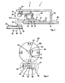
- Fig. 1 is a schematic side view of a printing unit and an object carrier of a pad printing machine of the invention
- Fig. 2 is a schematic top view of a pad printing machine of several printing units
- Fig. 3 is a schematic longitudinal section of an electric linear actuator (electrical adjusting cylinder) fitted with an inverted planetary roller threaded drive used in a pad printing machine of the invention
- Fig. 4 schematically shows a cross-section in the plane IV-IV of Fig. 3 .
- Fig. 5 is a schematic longitudinal section of a further embodiment mode of an electrical, adjusting linear-actuator (electrical adjusting cylinder) fitted with inverted planetary roller threaded drive to be used in a pad printing machine of the present invention.
- the pad printing machine schematically shown in Fig. 1 contains a printing unit 4.
- This printing unit 4 contains a printing-unit support 6 which directly rests on a printing plate 8 or, as shown in Fig. 1 , rests on a printing plate base 10, and which is reciprocated according to arrows 14 and 15 by an electric, adjusting linear-actuator 12 between the ink receiving position indicated in Fig. 1 by a solid line and an ink transfer position as indicated in said Figure by dashed lines.
- the adjusting linear-actuator 12 is configured between the printing plate support 10 and the printing unit 6 and may displace the former relative to the latter.
- An ink cup 16 is situated on the printing plate 8 and is kept stationary in a predetermined position by an ink cup support 18 and is shown in the ink receiving position of the printing plate 8 above at least one recess 20 in said plate 8, whereby ink contained in the ink cup 16 can enter the recess(es) 20.
- the minimum of one recess 20 is in the shape of the printed image (image or text) as yet to be printed.
- the ink cup 16 remains in the position shown in Fig. 1 even when the printing plate 8 is moved from the position shown in solid lines into forward into the ink transfer position wherein the printing plate 8 is denoted by the reference 8-2.
- a pad 22 can be lowered by means of a second electric, adjusting linear-actuator 24 (electric adjusting cylinder) from the upper initial position shown in Fig. 1 in the direction shown by an arrow 26 onto the recess(es) 20 of the printing plate 8, in order to absorb the printing ink therein.
- the pad 22 is moved upward as shown by an arrow 27 by means of the electric, adjusting linear-actuator 24.
- the printing plate 8 can be returned into its ink-receiving position shown by solid lines in Fig. 1 by means of the first electric, adjusting linear-actuator 12.
- the second electric, adjusting linear-actuator 24 is mechanically connected on one hand to a pad support 23 of the pad 22 and on the other hand by a pad support 29 to the printing unit 6.
- the pad 22 can be by means of the second electric, adjusting linear-actuator 24 again as indicated by the same vertical arrows 26 respectively 27 down onto an object to be printed 30 and then back up in order to transfer the ink to the object being printed 30.
- the object to be/being printed 30 is situated on an object carrier 32.
- This object carrier 32 may be configured to be stationary or be displaceable on an object base 34 by means of a third electric, adjusting linear-actuator 36 (electrical adjusting cylinder) between the printing position shown in Fig. 1 and an object deposition position away from said object printing position, for instance as indicated by the respective arrows 38 and 39.
- a third electric, adjusting linear-actuator 36 electric adjusting cylinder
- the further embodiment mode of a pad printing machine of the present invention shown in Fig. 2 contains several, for instance four printing units 4-1, 4-2, 4-3 and 4-4 which are mounted on a printing unit carrier 204 rotatable about a vertical axis of rotation 42, each of said printing units 4-1 through 4-4 corresponding to a printing unit 4 of Fig. 1 .
- These printing units 4-1 through 4-4 rotate jointly with the printing carrier 204 sequentially past a printing station 44 where an object 30 is printed.
- the object to be/being printed 30 again may be located on the object carrier 32.
- Said object carrier can be mounted on an object base 34.
- the object carrier 32 may be displaced by a third electric, adjusting linear-actuator 36 (electric adjusting cylinder) as indicated by the arrows 38 respectively 39.
- the printing unit carrier 204 of Fig. 2 may be rotated for instance by an electric or pneumatic actuator, in particular a rotational actuator, or by a fourth electric, adjusting linear-actuator 48 of which the linear displacement is converted as indicated by double arrow 49 by means of an idler mechanism 50 into a rotational displacement of the printing unit carrier 204, for instance clockwise as indicated by an arrow 52.
- Figs. 1 and 2 Identical/corresponding components shown in Figs. 1 and 2 are denoted by the same references below. There are variations: the printing unit carrier 6 and the object base 34 (or object carrier 32) of Fig. 1 may be separate components or they may be a single component.
- a fifth electric, adjusting linear-actuator 60 (electrical adjusting cylinder) may be used to horizontally displace the printing plate carrier 10 and/or a sixth electric, adjusting linear-actuator 62 may serve to position the ink cup 16 on the printing plate 8.
- the fifth and sixth linear adjusting actuators 60 respectively 62 are represented by dotted lines.
- the terminology of "first, second, third, fourth, fifth and sixth electric, adjusting linear-actuator” does not define a definite number nor a definite sequence of the electric, adjusting linear-actuators, instead it serves only to describe them individually and to distinguish between them.
- At least one of electric, adjusting linear-actuators (electric adjusting cylinder) 12, 24, 36, 48, 60 and/or 62 contains an inverted planetary roller threaded drive and also a computerized control associated with said drive which is programmed/programmable to match predetermined pad printing procedures.
- Possible embodiment modes of such electric, adjusting linear-actuators fitted with a planetary roller threaded drive and with a corresponding control illustratively are known from the EP 0 671 070 B1 patent document and are briefly discussed below.
- the electric, adjusting linear-actuator 312 schematically shown in Figs. 3 and 4 comprises an external pipe 314 fitted with an electric motor winding 316 on its inside so that said pipe and winding together constitute an electric motor stator 314/316.
- the motor winding 316 is driven by an electric control 318 and fed by it with electric power.
- the external pipe 314 comprises radially inside the motor winding 316 an inner pipe 320 that is fitted with an internal thread 322 and with permanent magnets 324 at its outside. Together with its permanent magnet 324, the inner pipe 320 constitutes the electric motor's rotor 320/324.
- planetary rollers 326 which are fitted with an outer thread 327 matching the inner thread 322 of the inner pipe 320 -- are distributed around the inner circumference of the inner pipe 320 and engage the inner thread 322 of the inner pipe 320.
- the outer thread 327 of the planetary rollers 326 also engages the external, circumferential grooves 328 of a drive segment 330 fashioned at one end of a drive spindle 332.
- the drive segment 330 is part of the drive spindle 332 or irrotationally joined to it.
- the drive spindle 332 may be solid or tubular.
- the outer circumferential grooves 328 of the drive segment 330 may consist of a threaded groove or of individual annular grooves.
- the planetary rollers 326 may be kept apart from each other for instance by rings 334 and 336.
- the planetary rollers 326 When rotating the rotor 320/324 constituted by the inner pipe 320 and the permanent magnets 324, the planetary rollers 326 are axially moved relative to the said pipe 320 in its inside thread 322. In the process the planetary rollers 326 axially entrain the drive segment 330 and the drive spindle 332 connected to or integral with said drive segment, as a result of which the said drive spindle is axially displaced relative to the inside pipe 320 and hence also relative to the outer pipe 314.
- the further electrical, adjusting linear-actuator 412 shown in Fig. 5 is similar to the linear adjusting actuator 312 of Figs. 3 and 4 , except that the circumferential spacings of the planetary rollers 428 are not kept apart by rings 334 and 336 but by gears 440 and 442 or toothed rings which are constituted on or affixed to the ends of the planetary rollers 426, and which mesh by their teeth with those of the gearing rings 446 respectively 448 that are constituted at or affixed to the drive spindle 432 on each side of its drive segment 330.
- the same reference numerals apply in Fig. 5 as they do in Figs. 3 and 4 where the components are the same. Being functionally identical, they are not described again with respect to Fig. 5 .
Landscapes
- Rotary Presses (AREA)
- Inking, Control Or Cleaning Of Printing Machines (AREA)
- Transmission Devices (AREA)
- Printing Methods (AREA)
Claims (2)
- Tampondruckmaschine, umfassend mindestens eine erste Unteranordnung (8, 10; 23; 32; 204; 29, 18), die bewegbar relativ zu mindestens einer zweiten Unteranordnung (6; 34) konfiguriert ist; weiterhin einen elektrischen Linearstellantrieb (12; 24; 36; 48; 60; 62; 312; 412), der mit der ersten bewegbaren Unteranordnung (8, 10; 23; 32; 204; 29, 18) mechanisch verbunden ist, um die mindestens eine bewegbare erste Unteranordnung relativ zur zweiten Unteranordnung (6; 34) zu bewegen,
wobei die mindestens eine bewegbare erste Unteranordnung (8, 10; 23; 32; 204; 29, 18), die mit dem Stellantrieb verbunden ist, mindestens eine der folgenden Komponenten ist: ein Klischee (8), ein Klischeeträger (10), ein Tamponträger (23), ein Objektträger (32), der ein zu bedruckendes oder gerade bedrucktes Objekt trägt, ein bewegbarer Druckwerkträger (204), der ein Tampondruckwerk (4) oder mindestens zwei Tampondruckwerke (4-1; 4-2; 4-3; 4-4) trägt, ein Tamponträger (29) und/oder ein Tintentopfträger (18);
wobei die Tampondruckmaschine weiterhin eine programmierte oder eine programmierbare Steuerung (318) umfasst, die mit dem Linearstellantrieb (12; 24; 36; 48; 60; 62; 312; 412) verbunden ist, um ihn zu steuern, dadurch gekennzeichnet, dass der elektrische Linearstellantrieb (12; 24; 36; 48; 60; 62; 312; 412) mit einem invertierten Planetenrollengewindetrieb (312; 412) ausgestattet ist. - Verwendung eines elektrischen Linearstellantriebs (12; 24; 36; 48; 60; 62; 312; 412) zum Bewegen und Positionieren mindestens einer bewegbaren ersten Unteranordnung (8, 10; 23; 32; 204; 29, 18) relativ zu mindestens einer zweiten Unteranordnung (6; 34) einer Tampondruckmaschine,
wobei die mindestens eine erste Unteranordnung mindestens eine der folgenden Komponenten umfasst: ein Klischee (8), einen Klischeeträger (10), einen Tamponträger (23), einen Objektträger (32), der ein zu bedruckendes oder gerade bedrucktes Objekt trägt, einen bewegbaren Druckwerkträger (204), der ein Tampondruckwerk (4) oder mindestens zwei Tampondruckwerke (4-1; 4-2; 4-3; 4-4) trägt, einen Tamponträger (29) und/oder einen Tintentopfträger (18); wobei der elektrische Linearstellantrieb (12; 24; 36; 48; 60; 62; 312; 412) dadurch gekennzeichnet ist, dass er einen invertierten Planetenrollengewindetrieb (312; 412) umfasst.
Priority Applications (1)
| Application Number | Priority Date | Filing Date | Title |
|---|---|---|---|
| PL09742475T PL2274170T3 (pl) | 2008-05-08 | 2009-04-15 | Maszyna do tampondruku z odwróconym napędem gwintowym z wałkiem planetarnym |
Applications Claiming Priority (2)
| Application Number | Priority Date | Filing Date | Title |
|---|---|---|---|
| DE102008022876A DE102008022876A1 (de) | 2008-05-08 | 2008-05-08 | Tampondruckmaschine |
| PCT/IB2009/051575 WO2009136302A1 (en) | 2008-05-08 | 2009-04-15 | Pad printing machine with inverted planetary roller threaded drive |
Publications (2)
| Publication Number | Publication Date |
|---|---|
| EP2274170A1 EP2274170A1 (de) | 2011-01-19 |
| EP2274170B1 true EP2274170B1 (de) | 2012-05-16 |
Family
ID=40740135
Family Applications (1)
| Application Number | Title | Priority Date | Filing Date |
|---|---|---|---|
| EP09742475A Active EP2274170B1 (de) | 2008-05-08 | 2009-04-15 | Tampondruckmaschine mit invertiertem planetengetriebe-rollantrieb |
Country Status (6)
| Country | Link |
|---|---|
| US (2) | US20110023737A1 (de) |
| EP (1) | EP2274170B1 (de) |
| CN (2) | CN105751680B (de) |
| DE (1) | DE102008022876A1 (de) |
| PL (1) | PL2274170T3 (de) |
| WO (1) | WO2009136302A1 (de) |
Families Citing this family (13)
| Publication number | Priority date | Publication date | Assignee | Title |
|---|---|---|---|---|
| DE102008022876A1 (de) * | 2008-05-08 | 2009-11-12 | Itw Morlock Gmbh | Tampondruckmaschine |
| KR101025250B1 (ko) * | 2010-10-22 | 2011-03-29 | 나준하 | 가로등용 글로브의 인쇄장치 및 이에 의한 글로브 |
| CN102069629A (zh) * | 2010-12-02 | 2011-05-25 | 杭州奥普特光学有限公司 | 转盘式双印头移印机 |
| US9796172B2 (en) * | 2013-05-07 | 2017-10-24 | Hector Rene Rodriguez | Apparatus, system, and method for marking a substrate |
| CN104441946A (zh) * | 2013-09-20 | 2015-03-25 | 天津中电华利电器科技集团有限公司 | 一种微型断路器移印设备 |
| DE102015205777B3 (de) * | 2015-03-31 | 2016-05-25 | Schaeffler Technologies AG & Co. KG | Hydraulischer Zugmittelspanner mit einem Druckregulator |
| JP6656971B2 (ja) * | 2016-03-24 | 2020-03-04 | 住友理工株式会社 | パッド印刷機 |
| CN106393966A (zh) * | 2016-08-30 | 2017-02-15 | 山东星宇手套有限公司 | 一种热敏压纹线自动印花装置 |
| CN107379745A (zh) * | 2017-07-20 | 2017-11-24 | 苏州市烨铭塑胶制品厂 | 一种用于带状物品的移印工作台 |
| FR3084663B1 (fr) * | 2018-07-31 | 2020-07-17 | Saint-Gobain Glass France | Procede et installation de primage de vitrage par tampographie mettant en oeuvre un solvant a base d'eau. |
| CN108839426A (zh) * | 2018-09-28 | 2018-11-20 | 天津尚吉液压设备有限公司 | 微型工业移印机 |
| KR102669746B1 (ko) * | 2019-02-18 | 2024-05-28 | 삼성디스플레이 주식회사 | 커버 글라스 인쇄용 패드, 이를 이용한 커버 글라스의 제조방법 및 이에 의해 제조된 커버 글라스 |
| CN111300977A (zh) * | 2020-04-18 | 2020-06-19 | 台州市莱恩克智能科技有限公司 | 一种拆卸方便的移印机底部凹版安装机构 |
Family Cites Families (12)
| Publication number | Priority date | Publication date | Assignee | Title |
|---|---|---|---|---|
| DE8328627U1 (de) * | 1983-10-05 | 1985-03-14 | Morlock Mechanik GmbH, 7292 Baiersbronn | Tampon-druckvorrichtung |
| DE3710534C1 (de) * | 1987-03-30 | 1988-06-01 | Tampoflex Gmbh | Vorrichtung zum Einstellen eines Satzes von Werkstuecktraegern in definierte Arbeitspositionen |
| DE3900121A1 (de) * | 1989-01-04 | 1990-07-19 | Inst Produktionstechnik Karlsr | Vorrichtung zur einstellung der axialen vorspannung von waelzlagern und spindelmuttern |
| US5557154A (en) | 1991-10-11 | 1996-09-17 | Exlar Corporation | Linear actuator with feedback position sensor device |
| DE19637526A1 (de) * | 1996-09-15 | 1998-03-19 | Gerd Hoermansdoerfer | Rollengewindetrieb |
| US6550381B1 (en) * | 2000-05-10 | 2003-04-22 | Illinois Tool Works Inc. | Transfer pad printing systems, plates and methods |
| JP4474034B2 (ja) * | 2000-09-19 | 2010-06-02 | 住友重機械工業株式会社 | コンベアローラ用駆動装置、駆動ローラ装置 |
| CN100382962C (zh) * | 2003-06-20 | 2008-04-23 | Itw莫克洛有限公司 | 移印头印刷机的可移动移印头支架 |
| EP1508907B1 (de) * | 2003-08-18 | 2015-05-06 | Greatbatch Ltd. | Druckverfahren zur Herstellung einer Kondensatorelektrode |
| JP4898123B2 (ja) * | 2005-01-13 | 2012-03-14 | Ntn株式会社 | 電動式直動アクチュエータおよび電動式ブレーキ装置 |
| DE102005060550A1 (de) * | 2005-12-17 | 2007-06-28 | Itw Morlock Gmbh | Tampondruckmaschine |
| DE102008022876A1 (de) * | 2008-05-08 | 2009-11-12 | Itw Morlock Gmbh | Tampondruckmaschine |
-
2008
- 2008-05-08 DE DE102008022876A patent/DE102008022876A1/de not_active Withdrawn
-
2009
- 2009-04-15 PL PL09742475T patent/PL2274170T3/pl unknown
- 2009-04-15 CN CN201610111411.7A patent/CN105751680B/zh not_active Expired - Fee Related
- 2009-04-15 WO PCT/IB2009/051575 patent/WO2009136302A1/en not_active Ceased
- 2009-04-15 EP EP09742475A patent/EP2274170B1/de active Active
- 2009-04-15 CN CN2009801170149A patent/CN102015306A/zh active Pending
- 2009-04-15 US US12/933,985 patent/US20110023737A1/en not_active Abandoned
-
2013
- 2013-04-19 US US13/866,485 patent/US10293596B2/en active Active
Also Published As
| Publication number | Publication date |
|---|---|
| US20130333581A1 (en) | 2013-12-19 |
| DE102008022876A1 (de) | 2009-11-12 |
| PL2274170T3 (pl) | 2012-11-30 |
| CN105751680B (zh) | 2020-05-08 |
| EP2274170A1 (de) | 2011-01-19 |
| CN105751680A (zh) | 2016-07-13 |
| CN102015306A (zh) | 2011-04-13 |
| WO2009136302A1 (en) | 2009-11-12 |
| US10293596B2 (en) | 2019-05-21 |
| US20110023737A1 (en) | 2011-02-03 |
Similar Documents
| Publication | Publication Date | Title |
|---|---|---|
| EP2274170B1 (de) | Tampondruckmaschine mit invertiertem planetengetriebe-rollantrieb | |
| US4413560A (en) | Flexographic printing press | |
| RU2554789C2 (ru) | Машина глубокой печати с подборочным цилиндром для краски | |
| US20100173762A1 (en) | Tool changer for machine tools | |
| JP6109417B2 (ja) | 証券印刷用の印刷機械及び印刷版を交換し、印刷機械を始動する方法 | |
| WO2010081515A2 (de) | Behälterbehandlungsmaschine | |
| CN104551677B (zh) | 一种筒型壳体自动化生产线 | |
| JP2016525949A (ja) | 印刷機械のインキを案内する回転体を作動させる方法及び装置 | |
| US6289805B1 (en) | Device and method for driving a printing cylinder | |
| CN100427236C (zh) | 具有电气旋转/升降驱动装置的冲压机 | |
| CN107199499A (zh) | 凸轮轴中心孔抛光装置 | |
| CN1746025A (zh) | 用于印刷滚筒毂的支撑和可释放的保持设备 | |
| CN109967771A (zh) | 一种转盘式孔钻装置 | |
| DE10219903A1 (de) | Zylinder einer Rotationsdruckmaschine | |
| JP2002052687A (ja) | 折畳装置の回転胴 | |
| CN105731125A (zh) | 一种印刷机用卷纸机构 | |
| EP3251853B1 (de) | Verfahren zur einstellung der position von formzylindern in einer rotationsdruckmaschine | |
| US20030029338A1 (en) | Printing machine for printing sheets and strips | |
| CN218613231U (zh) | 一种凸轮轴毛刺处理设备 | |
| US10286647B2 (en) | Processing unit and label printing machine having the processing unit | |
| CN108166166B (zh) | 一种旋转送料装置及双工位橡筋机 | |
| WO2020141322A1 (en) | Roller support | |
| CN213105361U (zh) | 一种油缸支耳固定装置 | |
| CN103507404B (zh) | 用于输送页张的传递辊 | |
| US7435210B2 (en) | Adjusting apparatus and method for a folding-unit cylinder |
Legal Events
| Date | Code | Title | Description |
|---|---|---|---|
| PUAI | Public reference made under article 153(3) epc to a published international application that has entered the european phase |
Free format text: ORIGINAL CODE: 0009012 |
|
| 17P | Request for examination filed |
Effective date: 20101012 |
|
| AK | Designated contracting states |
Kind code of ref document: A1 Designated state(s): AT BE BG CH CY CZ DE DK EE ES FI FR GB GR HR HU IE IS IT LI LT LU LV MC MK MT NL NO PL PT RO SE SI SK TR |
|
| AX | Request for extension of the european patent |
Extension state: AL BA RS |
|
| DAX | Request for extension of the european patent (deleted) | ||
| GRAP | Despatch of communication of intention to grant a patent |
Free format text: ORIGINAL CODE: EPIDOSNIGR1 |
|
| GRAS | Grant fee paid |
Free format text: ORIGINAL CODE: EPIDOSNIGR3 |
|
| GRAA | (expected) grant |
Free format text: ORIGINAL CODE: 0009210 |
|
| AK | Designated contracting states |
Kind code of ref document: B1 Designated state(s): AT BE BG CH CY CZ DE DK EE ES FI FR GB GR HR HU IE IS IT LI LT LU LV MC MK MT NL NO PL PT RO SE SI SK TR |
|
| REG | Reference to a national code |
Ref country code: GB Ref legal event code: FG4D |
|
| REG | Reference to a national code |
Ref country code: CH Ref legal event code: EP |
|
| REG | Reference to a national code |
Ref country code: AT Ref legal event code: REF Ref document number: 557882 Country of ref document: AT Kind code of ref document: T Effective date: 20120615 |
|
| REG | Reference to a national code |
Ref country code: IE Ref legal event code: FG4D |
|
| REG | Reference to a national code |
Ref country code: DE Ref legal event code: R096 Ref document number: 602009007088 Country of ref document: DE Effective date: 20120712 |
|
| REG | Reference to a national code |
Ref country code: NL Ref legal event code: T3 |
|
| REG | Reference to a national code |
Ref country code: LT Ref legal event code: MG4D Effective date: 20120516 |
|
| PG25 | Lapsed in a contracting state [announced via postgrant information from national office to epo] |
Ref country code: SE Free format text: LAPSE BECAUSE OF FAILURE TO SUBMIT A TRANSLATION OF THE DESCRIPTION OR TO PAY THE FEE WITHIN THE PRESCRIBED TIME-LIMIT Effective date: 20120516 Ref country code: CY Free format text: LAPSE BECAUSE OF FAILURE TO SUBMIT A TRANSLATION OF THE DESCRIPTION OR TO PAY THE FEE WITHIN THE PRESCRIBED TIME-LIMIT Effective date: 20120516 Ref country code: IS Free format text: LAPSE BECAUSE OF FAILURE TO SUBMIT A TRANSLATION OF THE DESCRIPTION OR TO PAY THE FEE WITHIN THE PRESCRIBED TIME-LIMIT Effective date: 20120916 Ref country code: LT Free format text: LAPSE BECAUSE OF FAILURE TO SUBMIT A TRANSLATION OF THE DESCRIPTION OR TO PAY THE FEE WITHIN THE PRESCRIBED TIME-LIMIT Effective date: 20120516 Ref country code: FI Free format text: LAPSE BECAUSE OF FAILURE TO SUBMIT A TRANSLATION OF THE DESCRIPTION OR TO PAY THE FEE WITHIN THE PRESCRIBED TIME-LIMIT Effective date: 20120516 Ref country code: NO Free format text: LAPSE BECAUSE OF FAILURE TO SUBMIT A TRANSLATION OF THE DESCRIPTION OR TO PAY THE FEE WITHIN THE PRESCRIBED TIME-LIMIT Effective date: 20120816 |
|
| REG | Reference to a national code |
Ref country code: AT Ref legal event code: MK05 Ref document number: 557882 Country of ref document: AT Kind code of ref document: T Effective date: 20120516 |
|
| PG25 | Lapsed in a contracting state [announced via postgrant information from national office to epo] |
Ref country code: GR Free format text: LAPSE BECAUSE OF FAILURE TO SUBMIT A TRANSLATION OF THE DESCRIPTION OR TO PAY THE FEE WITHIN THE PRESCRIBED TIME-LIMIT Effective date: 20120817 Ref country code: PT Free format text: LAPSE BECAUSE OF FAILURE TO SUBMIT A TRANSLATION OF THE DESCRIPTION OR TO PAY THE FEE WITHIN THE PRESCRIBED TIME-LIMIT Effective date: 20120917 Ref country code: HR Free format text: LAPSE BECAUSE OF FAILURE TO SUBMIT A TRANSLATION OF THE DESCRIPTION OR TO PAY THE FEE WITHIN THE PRESCRIBED TIME-LIMIT Effective date: 20120516 Ref country code: SI Free format text: LAPSE BECAUSE OF FAILURE TO SUBMIT A TRANSLATION OF THE DESCRIPTION OR TO PAY THE FEE WITHIN THE PRESCRIBED TIME-LIMIT Effective date: 20120516 Ref country code: LV Free format text: LAPSE BECAUSE OF FAILURE TO SUBMIT A TRANSLATION OF THE DESCRIPTION OR TO PAY THE FEE WITHIN THE PRESCRIBED TIME-LIMIT Effective date: 20120516 |
|
| REG | Reference to a national code |
Ref country code: PL Ref legal event code: T3 |
|
| PG25 | Lapsed in a contracting state [announced via postgrant information from national office to epo] |
Ref country code: BE Free format text: LAPSE BECAUSE OF FAILURE TO SUBMIT A TRANSLATION OF THE DESCRIPTION OR TO PAY THE FEE WITHIN THE PRESCRIBED TIME-LIMIT Effective date: 20120516 |
|
| PG25 | Lapsed in a contracting state [announced via postgrant information from national office to epo] |
Ref country code: SK Free format text: LAPSE BECAUSE OF FAILURE TO SUBMIT A TRANSLATION OF THE DESCRIPTION OR TO PAY THE FEE WITHIN THE PRESCRIBED TIME-LIMIT Effective date: 20120516 Ref country code: AT Free format text: LAPSE BECAUSE OF FAILURE TO SUBMIT A TRANSLATION OF THE DESCRIPTION OR TO PAY THE FEE WITHIN THE PRESCRIBED TIME-LIMIT Effective date: 20120516 Ref country code: EE Free format text: LAPSE BECAUSE OF FAILURE TO SUBMIT A TRANSLATION OF THE DESCRIPTION OR TO PAY THE FEE WITHIN THE PRESCRIBED TIME-LIMIT Effective date: 20120516 Ref country code: CZ Free format text: LAPSE BECAUSE OF FAILURE TO SUBMIT A TRANSLATION OF THE DESCRIPTION OR TO PAY THE FEE WITHIN THE PRESCRIBED TIME-LIMIT Effective date: 20120516 Ref country code: DK Free format text: LAPSE BECAUSE OF FAILURE TO SUBMIT A TRANSLATION OF THE DESCRIPTION OR TO PAY THE FEE WITHIN THE PRESCRIBED TIME-LIMIT Effective date: 20120516 Ref country code: RO Free format text: LAPSE BECAUSE OF FAILURE TO SUBMIT A TRANSLATION OF THE DESCRIPTION OR TO PAY THE FEE WITHIN THE PRESCRIBED TIME-LIMIT Effective date: 20120516 |
|
| PLBE | No opposition filed within time limit |
Free format text: ORIGINAL CODE: 0009261 |
|
| STAA | Information on the status of an ep patent application or granted ep patent |
Free format text: STATUS: NO OPPOSITION FILED WITHIN TIME LIMIT |
|
| 26N | No opposition filed |
Effective date: 20130219 |
|
| PG25 | Lapsed in a contracting state [announced via postgrant information from national office to epo] |
Ref country code: ES Free format text: LAPSE BECAUSE OF FAILURE TO SUBMIT A TRANSLATION OF THE DESCRIPTION OR TO PAY THE FEE WITHIN THE PRESCRIBED TIME-LIMIT Effective date: 20120827 |
|
| REG | Reference to a national code |
Ref country code: DE Ref legal event code: R097 Ref document number: 602009007088 Country of ref document: DE Effective date: 20130219 |
|
| PG25 | Lapsed in a contracting state [announced via postgrant information from national office to epo] |
Ref country code: BG Free format text: LAPSE BECAUSE OF FAILURE TO SUBMIT A TRANSLATION OF THE DESCRIPTION OR TO PAY THE FEE WITHIN THE PRESCRIBED TIME-LIMIT Effective date: 20120816 |
|
| PG25 | Lapsed in a contracting state [announced via postgrant information from national office to epo] |
Ref country code: MC Free format text: LAPSE BECAUSE OF FAILURE TO SUBMIT A TRANSLATION OF THE DESCRIPTION OR TO PAY THE FEE WITHIN THE PRESCRIBED TIME-LIMIT Effective date: 20120516 |
|
| GBPC | Gb: european patent ceased through non-payment of renewal fee |
Effective date: 20130415 |
|
| REG | Reference to a national code |
Ref country code: IE Ref legal event code: MM4A |
|
| PG25 | Lapsed in a contracting state [announced via postgrant information from national office to epo] |
Ref country code: GB Free format text: LAPSE BECAUSE OF NON-PAYMENT OF DUE FEES Effective date: 20130415 |
|
| PG25 | Lapsed in a contracting state [announced via postgrant information from national office to epo] |
Ref country code: IE Free format text: LAPSE BECAUSE OF NON-PAYMENT OF DUE FEES Effective date: 20130415 |
|
| PG25 | Lapsed in a contracting state [announced via postgrant information from national office to epo] |
Ref country code: MT Free format text: LAPSE BECAUSE OF FAILURE TO SUBMIT A TRANSLATION OF THE DESCRIPTION OR TO PAY THE FEE WITHIN THE PRESCRIBED TIME-LIMIT Effective date: 20120516 |
|
| PG25 | Lapsed in a contracting state [announced via postgrant information from national office to epo] |
Ref country code: HU Free format text: LAPSE BECAUSE OF FAILURE TO SUBMIT A TRANSLATION OF THE DESCRIPTION OR TO PAY THE FEE WITHIN THE PRESCRIBED TIME-LIMIT; INVALID AB INITIO Effective date: 20090415 Ref country code: MK Free format text: LAPSE BECAUSE OF FAILURE TO SUBMIT A TRANSLATION OF THE DESCRIPTION OR TO PAY THE FEE WITHIN THE PRESCRIBED TIME-LIMIT Effective date: 20120516 Ref country code: LU Free format text: LAPSE BECAUSE OF NON-PAYMENT OF DUE FEES Effective date: 20130415 |
|
| REG | Reference to a national code |
Ref country code: FR Ref legal event code: PLFP Year of fee payment: 8 |
|
| REG | Reference to a national code |
Ref country code: FR Ref legal event code: PLFP Year of fee payment: 9 |
|
| REG | Reference to a national code |
Ref country code: FR Ref legal event code: PLFP Year of fee payment: 10 |
|
| PGFP | Annual fee paid to national office [announced via postgrant information from national office to epo] |
Ref country code: TR Payment date: 20230329 Year of fee payment: 15 Ref country code: PL Payment date: 20230321 Year of fee payment: 15 |
|
| PGFP | Annual fee paid to national office [announced via postgrant information from national office to epo] |
Ref country code: NL Payment date: 20230426 Year of fee payment: 15 |
|
| PGFP | Annual fee paid to national office [announced via postgrant information from national office to epo] |
Ref country code: IT Payment date: 20230419 Year of fee payment: 15 Ref country code: FR Payment date: 20230425 Year of fee payment: 15 Ref country code: DE Payment date: 20230427 Year of fee payment: 15 Ref country code: CH Payment date: 20230502 Year of fee payment: 15 |
|
| P01 | Opt-out of the competence of the unified patent court (upc) registered |
Effective date: 20231101 |
|
| REG | Reference to a national code |
Ref country code: DE Ref legal event code: R119 Ref document number: 602009007088 Country of ref document: DE |
|
| REG | Reference to a national code |
Ref country code: CH Ref legal event code: PL |
|
| REG | Reference to a national code |
Ref country code: NL Ref legal event code: MM Effective date: 20240501 |
|
| PG25 | Lapsed in a contracting state [announced via postgrant information from national office to epo] |
Ref country code: DE Free format text: LAPSE BECAUSE OF NON-PAYMENT OF DUE FEES Effective date: 20241105 |
|
| PG25 | Lapsed in a contracting state [announced via postgrant information from national office to epo] |
Ref country code: NL Free format text: LAPSE BECAUSE OF NON-PAYMENT OF DUE FEES Effective date: 20240501 |
|
| PG25 | Lapsed in a contracting state [announced via postgrant information from national office to epo] |
Ref country code: FR Free format text: LAPSE BECAUSE OF NON-PAYMENT OF DUE FEES Effective date: 20240430 |
|
| PG25 | Lapsed in a contracting state [announced via postgrant information from national office to epo] |
Ref country code: NL Free format text: LAPSE BECAUSE OF NON-PAYMENT OF DUE FEES Effective date: 20240501 Ref country code: FR Free format text: LAPSE BECAUSE OF NON-PAYMENT OF DUE FEES Effective date: 20240430 Ref country code: DE Free format text: LAPSE BECAUSE OF NON-PAYMENT OF DUE FEES Effective date: 20241105 Ref country code: CH Free format text: LAPSE BECAUSE OF NON-PAYMENT OF DUE FEES Effective date: 20240430 |
|
| PG25 | Lapsed in a contracting state [announced via postgrant information from national office to epo] |
Ref country code: PL Free format text: LAPSE BECAUSE OF NON-PAYMENT OF DUE FEES Effective date: 20240415 |
|
| PG25 | Lapsed in a contracting state [announced via postgrant information from national office to epo] |
Ref country code: IT Free format text: LAPSE BECAUSE OF NON-PAYMENT OF DUE FEES Effective date: 20240415 |