EP2272460B1 - Superelastic endodontic instrument and method of manufacture therefor - Google Patents
Superelastic endodontic instrument and method of manufacture therefor Download PDFInfo
- Publication number
- EP2272460B1 EP2272460B1 EP10180880.6A EP10180880A EP2272460B1 EP 2272460 B1 EP2272460 B1 EP 2272460B1 EP 10180880 A EP10180880 A EP 10180880A EP 2272460 B1 EP2272460 B1 EP 2272460B1
- Authority
- EP
- European Patent Office
- Prior art keywords
- blank
- superelastic
- twisting
- file
- heating
- Prior art date
- Legal status (The legal status is an assumption and is not a legal conclusion. Google has not performed a legal analysis and makes no representation as to the accuracy of the status listed.)
- Expired - Lifetime
Links
- 238000000034 method Methods 0.000 title claims description 34
- 238000004519 manufacturing process Methods 0.000 title description 8
- 239000000463 material Substances 0.000 claims description 46
- 238000010438 heat treatment Methods 0.000 claims description 28
- 229910045601 alloy Inorganic materials 0.000 claims description 21
- 239000000956 alloy Substances 0.000 claims description 21
- 229910001566 austenite Inorganic materials 0.000 claims description 11
- 229910000734 martensite Inorganic materials 0.000 claims description 11
- 229910001000 nickel titanium Inorganic materials 0.000 claims description 7
- 239000010936 titanium Substances 0.000 claims description 7
- 238000005520 cutting process Methods 0.000 claims description 6
- 229910001257 Nb alloy Inorganic materials 0.000 claims description 2
- 229910004353 Ti-Cu Inorganic materials 0.000 claims description 2
- 229910011212 Ti—Fe Inorganic materials 0.000 claims description 2
- KHYBPSFKEHXSLX-UHFFFAOYSA-N iminotitanium Chemical compound [Ti]=N KHYBPSFKEHXSLX-UHFFFAOYSA-N 0.000 claims description 2
- 229910052751 metal Inorganic materials 0.000 claims description 2
- 239000002184 metal Substances 0.000 claims description 2
- 229910001069 Ti alloy Inorganic materials 0.000 claims 1
- 230000007246 mechanism Effects 0.000 description 19
- 239000007788 liquid Substances 0.000 description 17
- 230000008569 process Effects 0.000 description 9
- HZEWFHLRYVTOIW-UHFFFAOYSA-N [Ti].[Ni] Chemical compound [Ti].[Ni] HZEWFHLRYVTOIW-UHFFFAOYSA-N 0.000 description 5
- 239000010935 stainless steel Substances 0.000 description 5
- 229910001220 stainless steel Inorganic materials 0.000 description 5
- RTAQQCXQSZGOHL-UHFFFAOYSA-N Titanium Chemical compound [Ti] RTAQQCXQSZGOHL-UHFFFAOYSA-N 0.000 description 4
- 230000008901 benefit Effects 0.000 description 4
- 210000004262 dental pulp cavity Anatomy 0.000 description 4
- 230000006698 induction Effects 0.000 description 4
- 239000000203 mixture Substances 0.000 description 4
- 229910052719 titanium Inorganic materials 0.000 description 4
- 230000009466 transformation Effects 0.000 description 4
- 229910000831 Steel Inorganic materials 0.000 description 3
- 239000012266 salt solution Substances 0.000 description 3
- 239000010959 steel Substances 0.000 description 3
- 229910000975 Carbon steel Inorganic materials 0.000 description 2
- XEEYBQQBJWHFJM-UHFFFAOYSA-N Iron Chemical compound [Fe] XEEYBQQBJWHFJM-UHFFFAOYSA-N 0.000 description 2
- 230000001154 acute effect Effects 0.000 description 2
- 239000010962 carbon steel Substances 0.000 description 2
- 229910001092 metal group alloy Inorganic materials 0.000 description 2
- 229910052758 niobium Inorganic materials 0.000 description 2
- 239000010955 niobium Substances 0.000 description 2
- 238000010791 quenching Methods 0.000 description 2
- 230000000171 quenching effect Effects 0.000 description 2
- 230000000717 retained effect Effects 0.000 description 2
- 229910001369 Brass Inorganic materials 0.000 description 1
- OKTJSMMVPCPJKN-UHFFFAOYSA-N Carbon Chemical compound [C] OKTJSMMVPCPJKN-UHFFFAOYSA-N 0.000 description 1
- VYZAMTAEIAYCRO-UHFFFAOYSA-N Chromium Chemical compound [Cr] VYZAMTAEIAYCRO-UHFFFAOYSA-N 0.000 description 1
- 229910017518 Cu Zn Inorganic materials 0.000 description 1
- 229910000881 Cu alloy Inorganic materials 0.000 description 1
- 229910017752 Cu-Zn Inorganic materials 0.000 description 1
- 229910017943 Cu—Zn Inorganic materials 0.000 description 1
- ZOKXTWBITQBERF-UHFFFAOYSA-N Molybdenum Chemical compound [Mo] ZOKXTWBITQBERF-UHFFFAOYSA-N 0.000 description 1
- ATJFFYVFTNAWJD-UHFFFAOYSA-N Tin Chemical compound [Sn] ATJFFYVFTNAWJD-UHFFFAOYSA-N 0.000 description 1
- QCWXUUIWCKQGHC-UHFFFAOYSA-N Zirconium Chemical compound [Zr] QCWXUUIWCKQGHC-UHFFFAOYSA-N 0.000 description 1
- WCERXPKXJMFQNQ-UHFFFAOYSA-N [Ti].[Ni].[Cu] Chemical compound [Ti].[Ni].[Cu] WCERXPKXJMFQNQ-UHFFFAOYSA-N 0.000 description 1
- 238000005452 bending Methods 0.000 description 1
- 230000036760 body temperature Effects 0.000 description 1
- 238000009835 boiling Methods 0.000 description 1
- 239000010951 brass Substances 0.000 description 1
- 230000008859 change Effects 0.000 description 1
- 229910052804 chromium Inorganic materials 0.000 description 1
- 239000011651 chromium Substances 0.000 description 1
- TVZPLCNGKSPOJA-UHFFFAOYSA-N copper zinc Chemical compound [Cu].[Zn] TVZPLCNGKSPOJA-UHFFFAOYSA-N 0.000 description 1
- 239000013078 crystal Substances 0.000 description 1
- 239000012467 final product Substances 0.000 description 1
- 239000012530 fluid Substances 0.000 description 1
- 230000001939 inductive effect Effects 0.000 description 1
- 229910052742 iron Inorganic materials 0.000 description 1
- 238000012423 maintenance Methods 0.000 description 1
- 238000012986 modification Methods 0.000 description 1
- 230000004048 modification Effects 0.000 description 1
- 229910052750 molybdenum Inorganic materials 0.000 description 1
- 239000011733 molybdenum Substances 0.000 description 1
- 229910052759 nickel Inorganic materials 0.000 description 1
- PXHVJJICTQNCMI-UHFFFAOYSA-N nickel Substances [Ni] PXHVJJICTQNCMI-UHFFFAOYSA-N 0.000 description 1
- GUCVJGMIXFAOAE-UHFFFAOYSA-N niobium atom Chemical compound [Nb] GUCVJGMIXFAOAE-UHFFFAOYSA-N 0.000 description 1
- 230000000704 physical effect Effects 0.000 description 1
- 238000003672 processing method Methods 0.000 description 1
- 238000012552 review Methods 0.000 description 1
- 229910001285 shape-memory alloy Inorganic materials 0.000 description 1
- 229910052718 tin Inorganic materials 0.000 description 1
- 229910052720 vanadium Inorganic materials 0.000 description 1
- LEONUFNNVUYDNQ-UHFFFAOYSA-N vanadium atom Chemical compound [V] LEONUFNNVUYDNQ-UHFFFAOYSA-N 0.000 description 1
- 229910052726 zirconium Inorganic materials 0.000 description 1
Images


Classifications
-
- B—PERFORMING OPERATIONS; TRANSPORTING
- B24—GRINDING; POLISHING
- B24B—MACHINES, DEVICES, OR PROCESSES FOR GRINDING OR POLISHING; DRESSING OR CONDITIONING OF ABRADING SURFACES; FEEDING OF GRINDING, POLISHING, OR LAPPING AGENTS
- B24B19/00—Single-purpose machines or devices for particular grinding operations not covered by any other main group
- B24B19/02—Single-purpose machines or devices for particular grinding operations not covered by any other main group for grinding grooves, e.g. on shafts, in casings, in tubes, homokinetic joint elements
- B24B19/022—Single-purpose machines or devices for particular grinding operations not covered by any other main group for grinding grooves, e.g. on shafts, in casings, in tubes, homokinetic joint elements for helicoidal grooves
-
- A—HUMAN NECESSITIES
- A61—MEDICAL OR VETERINARY SCIENCE; HYGIENE
- A61C—DENTISTRY; APPARATUS OR METHODS FOR ORAL OR DENTAL HYGIENE
- A61C5/00—Filling or capping teeth
- A61C5/40—Implements for surgical treatment of the roots or nerves of the teeth; Nerve needles; Methods or instruments for medication of the roots
- A61C5/42—Files for root canals; Handgrips or guiding means therefor
-
- B—PERFORMING OPERATIONS; TRANSPORTING
- B24—GRINDING; POLISHING
- B24B—MACHINES, DEVICES, OR PROCESSES FOR GRINDING OR POLISHING; DRESSING OR CONDITIONING OF ABRADING SURFACES; FEEDING OF GRINDING, POLISHING, OR LAPPING AGENTS
- B24B19/00—Single-purpose machines or devices for particular grinding operations not covered by any other main group
- B24B19/02—Single-purpose machines or devices for particular grinding operations not covered by any other main group for grinding grooves, e.g. on shafts, in casings, in tubes, homokinetic joint elements
- B24B19/04—Single-purpose machines or devices for particular grinding operations not covered by any other main group for grinding grooves, e.g. on shafts, in casings, in tubes, homokinetic joint elements for fluting drill shanks
-
- A—HUMAN NECESSITIES
- A61—MEDICAL OR VETERINARY SCIENCE; HYGIENE
- A61C—DENTISTRY; APPARATUS OR METHODS FOR ORAL OR DENTAL HYGIENE
- A61C2201/00—Material properties
- A61C2201/007—Material properties using shape memory effect
Definitions
- the present invention generally relates to superelastic endodontic instruments and, more specifically, to instruments such as files or reamers and methods and apparatus for manufacturing such instruments.
- endodontic instruments such as root canal files have been manufactured by simultaneously grinding and twisting thin carbon steel or stainless steel rods or wires.
- steel wire blanks are first ground to the desired cross sectional shape, such as square, triangular or rhomboid, and to the appropriate size and taper.
- the ground blank is then gripped at one end and spring loaded jaws are brought into contact with the ground portion of the blank.
- the jaws are moved axially away from that end.
- the jaws therefore twist the rotating blank and form helical flutes into the blank.
- the longitudinal, ground edges of the blank form helical cutting edges on the file.
- the axial jaw speed, twisting speed and spring force are controlled to obtain the desired helical configuration.
- DE3429277 discloses a device and a method for making an endodontic file based on these principles.
- EP 0719523 discloses a root canal treatment instrument having a working section made of a superelastic alloy. The instrument is formed from the alloy by a removing process such as grinding. These direct grinding methods are time consuming and expensive. They also limit the variety of cross sectional shapes that may be formed in the final product.
- the present invention provides a superelastic endodontic instrument as defined in claim 1, which is preferably a file or reamer, having increased torsional and bending flexibility, as compared to conventional steel files, and manufactured by improved processes relative to prior superelastic file production techniques.
- the invention provides a process as defined in claim 7 in which a superelastic endodontic instrument preform or blank may be ground and then twisted with plastic deformation, that is, maintenance of the twisted shape, without over-stressing the material into failure.
- the unique process of this invention involves maintaining the instrument blank in the austenite phase of the superelastic material at least prior to twisting and, preferably, prior to and during the twisting operation.
- the blank is preferably maintained above the austenite finish temperature (A f ) of the particular superelastic material.
- the blank is more preferably maintained in the working temperature range T w of the superelastic material. For a wide variety of superelastic alloys, this range would be between 93°C - 204°C (200°F - 400°F).
- the material of the blank is converted from the austenite phase to the martensite phase by the stress applied during the twisting operation.
- the material undergoing stress induced martensite transformation is plastically deformed during twisting so that the fluted profile is retained after completion of the twisting process. Due to the ability to pregrind a file blank, for example, it is possible to fabricate a superelastic endodontic file having many different transverse cross sectional shapes, such as those conventionally obtained with steel materials.
- the elevation in temperature to the austenite finish temperature A f of the superelastic blank may be accomplished through several different methods, such as ambient, induction, joulian, or radiant heating, or submersion within a heated liquid.
- Ambient heating for example, may be accomplished in an oven while induction heating may utilize an inductive heating coil surrounding the blank during the twisting operation.
- Submersion within a heated liquid can allow the blank to be heated in a rapid and controlled manner.
- the heated liquid may be oil or a salt solution, or other liquids that do not boil below or close to the A f of the particular superelastic metal.
- Fluting apparatus is provided generally above a vessel containing the liquid and includes a rotary motion mechanism for holding and rotating an instrument blank, such as a file blank, a clamping mechanism that receives a ground portion of the file blank and a linear or axial motion mechanism for moving the clamping mechanism along the longitudinal axis of the file blank at a rate which is proportional to the rate of rotation.
- the twisting operation is preferably performed with the ground portion of the blank submerged in the heated liquid. After the twisting process is complete, the fluted, superelastic file may then undergo subsequent quenching or heat treatment operations in order to achieve the desired physical properties.
- Superelastic materials are typically metal alloys which return to their original shape after substantial deformation.
- Superelastic alloys such as nickel titanium (NiTi) can withstand several times more strain than conventional materials, such as stainless steel, without becoming plastically deformed. Further, a superelastic material will generally recover approximately 6% after twisting at ambient temperature while a stainless steel will recover only 1-2% after twisting.
- superelastic alloys undergo a stress induced martensitic transformation which allows for shape memory properties.
- NiTi near-equiatomic Ni-Ti, for example, 50.8 atomic percent Ti and 49.2 atomic percent Ni, Ni-Ti-Cu, Ni-Ti-Nb and Ni-Ti-Fe alloys as well as beta-phase titanium or other Ti based alloys.
- suitable nickel-titanium alloys in various stoichiometric ratios are disclosed in U.S. Patent No. 5,044,947 (nickel-titanium-copper alloy) and U.S. Patent Applications 08/221,638 and 08/454,016, inventor Sachdeva et al. , entitled “NiTiNb Alloy Processing Method and Articles Formed Thereby" (nickel-titanium-niobium-alloy).
- the specific alloy composition used for the endodontic instrument of this invention is not critical as the invention may utilize many materials which exhibit superelastic characteristics.
- U.S. Patent No. 5,429,501 discloses superelastic and shape memory beta-phase titanium.
- metallic titanium may be alloyed with molybdenum, chromium, zirconium, tin, vanadium, iron or niobium.
- Other compositions such as Cu-Zn alloys are also known to be superelastic and are suitable for use in the present invention.
- Another material suitable for use in the present invention is a work hardened nickel titanium having a martensitic crystal structure, such as that sold under the tradename NITANOL for orthodontic wires by Unitek Corp., Arcadia California.
- Superelastic materials have a temperature range in which the material may be permanently deformed. This range is known as the working temperature range T w .
- T w the working temperature range
- the wire When a superelastic wire is heated to a temperature in the working temperature range T w , the wire may be permanently deformed so that when the wire is cooled, the deformed shape is maintained.
- the superelastic wire is packaged in coils and should be straightened prior to grinding and twisting.
- One method of straightening the wire 8 is to wrap the wire around a mandrel 160 as shown in Fig. 6 . The mandrel 160 is then placed in a furnace and the wire 8 is heated into the T w . The wire 8 is then cooled, removed from the mandrel and the curved ends are trimmed.
- Superelastic alloys are in the martensitic phase when they are below the austenitic transformation temperature A f , i.e., the temperature at which the material is about 100% austenite. These alloys retain their deformed shape when subjected to stress in the martensitic phase. However, the shape memory property returns the deformed material to its original predeformation configuration when heated above A f .
- a f temperature lower than about 37° C (i.e., body temperature) so that the instrument will be in the austenitic phase during use in the human body.
- the material When the superelastic material is twisted, the material may form a stress induced martensite phase since less energy is necessary to stress induce and deform martensite than to deform austenite. If the file preform is deformed at room temperature and there is not enough strain to induce plastic deformation of the martensite phase, the wire will spring back to its original shape once the twisting force is released. It is also possible to permanently deform superelastic material by heating within the Tw range prior to and during twisting. A typical superelastic material will have a T w range of 93°C - 204°C (200°F - 400°F). Another method of permanently deforming a preform or blank according to the invention is by performing a rapid twist step to heat the superelastic material by internal friction to a temperature at which the material forms a stress induced martensite.
- shape-memory alloy and superelastic material or alloy or similar terms are intended to include all suitable alloy compositions which possess shape-memory and/or superelastic properties, respectively.
- superelastic is intended to mean the ability of a material to withstand at least twice as much strain as stainless steel materials can withstand without plastic deformation.
- shape memory is intended to mean the ability of a wire to recover to its original state by the use of temperature.
- rhombus or rhomboidal is intended to define a geometric shape, having four major sides, which is substantially a parallelogram, i.e., including four equal sides and no internal right angles.
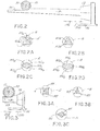
- file preforms or blanks Prior to twisting, file preforms or blanks are ground to the desired shape, including length, transverse cross-section and taper, on any one of the devices shown in Figs. 2, 3 , or 5 .
- cylindrical superelastic rods or wires 8 are ground to form file preforms or blanks 12 which are subsequently twisted to form helically fluted files 11.
- Cylindrical rod or wire 8 is mounted into collet 52 which is fixedly mounted upon a stage 54 which is selectively horizontally movable in opposite directions as designated by arrows 55a and 55b.
- stage 54 is then advanced horizontally rightwardly, as is seen in Fig. 2 , to move collet 52 and rod 8 axially so that a flat surface 101 is ground on one side of the rod 8.
- grinding wheel 50 is lifted vertically, and stage 54 is moved axially leftwardly to the initial or home position so that the grinding wheel 50 is aligned with the upper portion of the inner end of the working length of the partially ground rod.
- Collet 52 is then indexed about its central axis by a predetermined angle, the magnitude of which depends on the number of flutes desired in the finished file. Indexing rotational angles of 180°, 120° and 90° are employed for 2, 3 and 4 flute files, respectively. It is also possible to rotate the collet by a series of angles (e.g.
- apices 103 As noted, by varying the angle which collet 52 indexes rod 8, it is possible to form file blanks having three or more apices 103 shown generally in Figs. 2A-2C .
- endodontic files include three or four apices or helical cutting edges 103.
- rod 8 is indexed 90° after each flat surface 101 is ground.
- the rod is indexed 120° after each flat surface is formed (as shown in Fig. 2B ).
- a file having a rhomboidal transverse cross section Fig. 2C ). This is accomplished by grinding a first flat surface 101c 1 ; indexing the rod 60° clockwise as viewed in Fig. 2C and grinding a second flat surface 101c 2 ; indexing the rod 120° clockwise as viewed in Fig.
- the initial depth of cut may be adjusted prior to forming each flat side or may be adjusted after opposing pairs of edges are ground. For example, as seen in Fig.
- a first flat side 101d 1 is ground; the rod 8 is then indexed 90°, the initial depth of cut reduced and a second flat side 101d 2 is ground; rod 8 is then indexed 90°, the initial depth of cut is increased to the depth used for the cut of side 101d 1 and a third flat side 101d 3 is ground; rod 8 is then indexed 90°, the initial depth of cut is reduced to the depth used for the cut of side 101d 2 and fourth side 101d 4 is ground. It is also possible to grind flat side 101d 1 , index the rod 180°, and grind flat side 101d 4 ; index the rod 90° and decrease the initial depth of cut and grind flat side 101d 2 ; and finally index the rod 180° and grinding the final flat side 101d 3 .
- Figs. 2A-2C when the surface of the grinding wheel 50 is flat ( Fig. 2 ). While angle A is more acute and provides a sharper cutting edge, that edge is weaker due to the lower amount of material at the apex. Thus, the apices shown in Figs. 2A-2C are more rugged to maintain a usable edge and provide for a longer working life.
- FIG. 5 shows a wide grinding wheel 120 which moves transversely to the longitudinal axes of a large number of rods 8 to grind a flat surface onto the rods.
- the cylindrical rods 8 are placed upon rest 122.
- the rods 8 are disposed in parallel and extend along substantially the entire width of the rest 122.
- the parallel rods 8 are held by retainer 124 which is movable along the length of rest 122 as shown by opposing arrows 128a and 128b.
- Movable retainer 124 includes lateral projection 124a which extends over an end portion of rods 8 to secure the rods to rest 122 and prevent the rotation of the rods during grinding.
- grinding wheel 120 moves back and forth across the width of rest 122 to grind a flat surface on the entire working length of each rod 8.
- the grinding 120 wheel moves across each rod twice, once while traveling away from projection 124a and once while traveling toward projection 124a.
- the wheel 120 may be moved straight across the rods or may move in a figure eight or zigzag pattern.
- the grinding wheel is preferably a porous wheel such as an ANSI standard C-60IV wheel rotating at rate between 914 and 2438 surface metres per minute (3,000 and 8,000 surface feet per minute) and preferably about 1524 surface metres per minute (5,000 surface feet per minute).
- the material is passed under the wheel at a feed rate between about 15 and 30 lineal metres per minute (50 and 100 lineal feet per minute), and preferably about 23 lineal metres per minute (75 lineal feet per minute).
- the movable retainers 124 is translated with respect to the rest 122.
- the lateral projection 124a of the retainers 124 remains in contact with rods 8 so that the movement of the retainer along the direction shown by arrows 128a, 128b causes each rod to rotate by a predetermined angle about the longitudinal axis of the rods 8.
- a second flat surface is ground across the working length of the rod.
- the rods 8 are typically rotated and ground one or more times.
- the superelastic file blanks After the superelastic file blanks have been ground to the desired cross-sectional file preform shape they are preferably heated to a temperature above ambient temperature prior to, during and subsequent to the twisting operation using thermal or frictional energy or a combination thereof. This temperature is preferably above the austenite finish temperature A f of the particular superelastic material and can be as high as the working temperature range T w of the material.
- the heating process may externally heat the wire preform in the collet 14 by the provision of induction coils, radiant heating elements or electrodes to provide for joulian heating.
- the temperature to which the preform is heated is based upon the specific alloy used. A temperature range of 93°C - 204°C (200°F - 400°F) is contemplated to be typical.
- the files can be heated without the application of heat from an external heat source by twisting rapidly so that internal friction heats the file.
- the twisting apparatus 10 shown in Fig. 1 , includes a drive head 9 which rotates about a horizontal axis. Extending from the drive head 9 is a collet 14 which circumferentially grips and secures the proximal or inner end of a preformed ground file blank 12 for rotation about the longitudinal axis thereof. The distal or outer end portion of the file blank 12 is secured by opposing jaws 20, 22, which are mounted on a stage 28 which moves parallel to the longitudinal axis of the file blank (horizontally as shown in Fig.
- At least one of the jaws includes a spring or air cylinder 16 so that it may be compressed against the opposing jaw with a constant force.
- Each jaw includes a protectant layer 24, 26 which is malleable and able to withstand the working temperature of the file blank 12. Brass is one material known to be suitable.
- the jaws 20, 22 are provided with a new protectant layer 24, 26 from strips 29, 30 from a source 32, 34 such as take-off reels.
- the protectant layer may optionally be contacted by a heating element 25, 27 which may heat by any suitable process, such as an electrical heating process of joulian, radiant or induction heating or may be supplied with a heated fluid such as steam or oil.
- the heat treatment may be performed in any furnace with air circulation.
- the radiant heating elements or electrodes to provide for joulian heating can be used for the post twist heat treatment.
- the files are made in a variety of working lengths varying from 19-30 mm.
- the specific variables which are typically controlled in fabricating such files are set forth in the Tables 1 and 2.
- the variables A and B represent the minimum thickness of the transverse cross section at 16.00 mm and 3.00 mm, respectively, from the tip.
- the variables C and D represent the maximum thickness of the transverse cross section at 16.00 mm and 3.00 mm, respectively, from the tip.
- Table 1 describes the characteristics of a twisted rhomboidal file.
- Tight Flute Limit includes two values. The first value is the minimum acceptable length of a small flute 151 resulting from the twisting of the minor axis of the rhombus. The second value is the minimum acceptable length of a large flute 153 resulting from the twisting of the major axis of the rhombus.
- Loose Flute Limit includes two values.
- the first value is the maximum acceptable length of a small flute 151 resulting from the twisting of the minor axis of the rhombus.
- the second value is the maximum acceptable length of a large flute 153 resulting from the twisting of the major axis of the rhombus.
- T max represents the maximum acceptable length of the untwisted portion, at the distal tip of the file.
- L is the length of the ground portion of the rod.
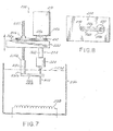
- Apparatus 200 generally comprises a rotary motion mechanism 204 operatively connected to a linear or axial motion mechanism 206 similar to apparatus 10 of Fig. 1 .
- Each mechanism 204, 206 is connected to file blank 202 for purposes to be described.
- Rotary motion mechanism 204 and linear motion mechanism 206 may be conventional mechanisms known in the art for forming helical flutes on endodontic files.
- Each mechanism 204, 206 is operated by a suitable electric motor 210.
- a gear drive 212 is connected in a conventional manner between an output 210a of motor 210 and linear motion mechanism 206 to convert the rotary motion of motor 210 into linear motion.
- Gear drive 212 is shown to simply include two gears 212a, 212b, for simplicity, but it will be understood that idler gears may be used between gears 212a, 212b. Such idler gears are conventionally used to set the material feed rate.
- a support plate 220 is provided generally for connecting rotary motion mechanism 204 to linear motion mechanism 206. Support plate 220 can also serve as a mounting plate for a mechanism (not shown) used to raise and lower apparatus 200, for reasons to be described.
- Rotary motion mechanism 204 further comprises a rotary shaft 222 which may be directly coupled to output shaft 210a of motor 210.
- a conventional collet 224 is provided for holding a proximal end of superelastic file blank 202.
- Superelastic file blank 202 further has its ground portion or working length held between a pair of spring-loaded clamping jaws 226, 228, as best shown in Fig. 8 .
- Clamping jaws 226, 228 are held at a relative lower end 230a of a clamping jaw support 230.
- Clamping jaw support 230 preferably has a conventional biasing mechanism to force jaws 226, 228 toward one another with a desired clamping force.
- clamping jaw support 230 holds a helical threaded shaft 232 for rotation at a relative upper end 230b.
- Helical threaded shaft 232 is also held within internal threads of gear member 212a of gear drive 212 such that, upon operation of gear drive 212 by motor 210, gear member 212a will rotate and also rotate helical threaded shaft 232. This will move shaft 232 linearly along its longitudinal axis thereby moving jaw support 230 and jaws 226, 228 along the length of the pre-ground superelastic file blank 202.
- a heated liquid 234 contained in a vessel 236 receives the ground portion of file blank 202 during a twisting and fluting operation.
- the heated liquid media 234 may, for example, comprise a salt solution or other suitable liquids such as oil.
- the chosen liquid will have a boiling temperature preferably above the A f temperature or even above the T w of the particular superelastic material.
- a suitable operating temperature for liquid 234 is approximately 500°C or above. Again, it is preferable that the liquid does boil at the chosen operating temperature.
- Liquid 234 may be heated by any conventional manner, such as with an electrical heating element 238 or a heating jacket.
- one contemplated example involves placing a ground file blank 202, formed of a superelastic metallic alloy and formed with a rhomboid cross section as generally described above, within collet 224. Clamping jaws 226, 228 may then be placed about a proximal, ground end of file blank 202 adjacent collet 224. Apparatus 200 may then be lowered toward a heated liquid comprised of a salt solution heated to a temperature of about 500°C. Blank 202 should be lowered until the ground portion is submerged within heated liquid 234.
- a fluting operation may be carried out by moving linear or axial motion mechanism 206 downwardly at a speed of about 6 inches/min. Rotation of blank 202 may be carried out by mechanism 204 at a corresponding rate which forms a desired number of twists.
- the fluting jaws 226, 228 reach the relative lower tip end of ground file blank 202, the fluting operation is complete and apparatus 200 may be lifted from heated liquid 234 and removed from collet 224. Quenching or heat treating of the finished file may then be carried out if appropriate.
Landscapes
- Health & Medical Sciences (AREA)
- Engineering & Computer Science (AREA)
- Mechanical Engineering (AREA)
- Oral & Maxillofacial Surgery (AREA)
- Epidemiology (AREA)
- Neurosurgery (AREA)
- Nuclear Medicine, Radiotherapy & Molecular Imaging (AREA)
- Surgery (AREA)
- Biomedical Technology (AREA)
- Dentistry (AREA)
- Neurology (AREA)
- Life Sciences & Earth Sciences (AREA)
- Animal Behavior & Ethology (AREA)
- General Health & Medical Sciences (AREA)
- Public Health (AREA)
- Veterinary Medicine (AREA)
- Dental Tools And Instruments Or Auxiliary Dental Instruments (AREA)
Applications Claiming Priority (3)
| Application Number | Priority Date | Filing Date | Title |
|---|---|---|---|
| US09/014,139 US6149501A (en) | 1997-09-26 | 1998-01-27 | Superelastic endodontic instrument, method of manufacture, and apparatus therefor |
| PCT/US1999/000895 WO1999037235A2 (en) | 1998-01-27 | 1999-01-15 | Superelastic endodontic instrument, method of manufacture, and apparatus therefor |
| EP99902283.3A EP1051125B1 (en) | 1998-01-27 | 1999-01-15 | Superelastic endodontic instrument, method of manufacture, and apparatus therefor |
Related Parent Applications (3)
| Application Number | Title | Priority Date | Filing Date |
|---|---|---|---|
| EP99902283.3A Division EP1051125B1 (en) | 1998-01-27 | 1999-01-15 | Superelastic endodontic instrument, method of manufacture, and apparatus therefor |
| EP99902283.3A Division-Into EP1051125B1 (en) | 1998-01-27 | 1999-01-15 | Superelastic endodontic instrument, method of manufacture, and apparatus therefor |
| EP99902283.3 Division | 1999-01-15 |
Publications (3)
| Publication Number | Publication Date |
|---|---|
| EP2272460A2 EP2272460A2 (en) | 2011-01-12 |
| EP2272460A3 EP2272460A3 (en) | 2012-12-26 |
| EP2272460B1 true EP2272460B1 (en) | 2018-10-24 |
Family
ID=21763778
Family Applications (2)
| Application Number | Title | Priority Date | Filing Date |
|---|---|---|---|
| EP10180880.6A Expired - Lifetime EP2272460B1 (en) | 1998-01-27 | 1999-01-15 | Superelastic endodontic instrument and method of manufacture therefor |
| EP99902283.3A Expired - Lifetime EP1051125B1 (en) | 1998-01-27 | 1999-01-15 | Superelastic endodontic instrument, method of manufacture, and apparatus therefor |
Family Applications After (1)
| Application Number | Title | Priority Date | Filing Date |
|---|---|---|---|
| EP99902283.3A Expired - Lifetime EP1051125B1 (en) | 1998-01-27 | 1999-01-15 | Superelastic endodontic instrument, method of manufacture, and apparatus therefor |
Country Status (7)
| Country | Link |
|---|---|
| US (1) | US6149501A (enExample) |
| EP (2) | EP2272460B1 (enExample) |
| JP (2) | JP4540024B2 (enExample) |
| AU (1) | AU2230299A (enExample) |
| CO (1) | CO4840516A1 (enExample) |
| TW (1) | TW462883B (enExample) |
| WO (1) | WO1999037235A2 (enExample) |
Families Citing this family (48)
| Publication number | Priority date | Publication date | Assignee | Title |
|---|---|---|---|---|
| US7249414B2 (en) | 1999-09-10 | 2007-07-31 | Micro Mega, S.A. | Method for making a root canal instrument |
| FR2798277B1 (fr) * | 1999-09-10 | 2002-04-19 | Micro Mega Sa | Instrument canalaire du type alesoir dentaire et procedes de realisation |
| US7094055B2 (en) * | 2001-05-30 | 2006-08-22 | Steven Senia | Endodontic reamer and a method for manufacturing endodontic reamers and files |
| US6966774B2 (en) * | 2001-08-16 | 2005-11-22 | Cloudland Institute, Llc. | Endodontic instrument having notched cutting surfaces |
| US6783438B2 (en) * | 2002-04-18 | 2004-08-31 | Ormco Corporation | Method of manufacturing an endodontic instrument |
| US7779542B2 (en) * | 2002-04-18 | 2010-08-24 | Ormco Corporation | Method of manufacturing a dental instrument |
| DE10233030B3 (de) * | 2002-07-20 | 2004-02-19 | Gebr. Brasseler Gmbh & Co. Kg | Wurzelkanalinstrument |
| US20060265858A1 (en) * | 2002-08-15 | 2006-11-30 | Mcspadden John T | Endodontic instrument having notched cutting surfaces |
| US20080213720A1 (en) * | 2003-05-13 | 2008-09-04 | Ultradent Products, Inc. | Endodontic instruments manufactured using chemical milling |
| US6968619B2 (en) * | 2003-05-13 | 2005-11-29 | Ultradent Products, Inc. | Method for manufacturing endodontic instruments |
| JP4186713B2 (ja) * | 2003-05-29 | 2008-11-26 | マニー株式会社 | 根管治療器具及び製造方法 |
| EP1734884B1 (en) | 2004-03-16 | 2021-06-16 | Guidance Endodontics, LLC | Endodontic files |
| JP4247346B2 (ja) * | 2004-03-30 | 2009-04-02 | マニー株式会社 | 治療器具用の断面角形先細棒の研削方法及び治療器具 |
| EP3058891B1 (en) | 2004-06-08 | 2019-11-06 | Gold Standard Instruments, LLC | Dental instruments comprising titanium |
| DE102004029065A1 (de) | 2004-06-16 | 2006-01-26 | Siemens Ag | Kurbelwellensynchrone ERfassung analoger Signale |
| US20060008766A1 (en) * | 2004-07-09 | 2006-01-12 | Fischer Dan E | Dental instruments made from super-elastic alloys |
| JP4621851B2 (ja) * | 2004-11-29 | 2011-01-26 | マニー株式会社 | 根管治療器具 |
| FR2886837B1 (fr) | 2005-06-14 | 2008-04-11 | Micro Mega Int Mfg Sa | Ebauche pour la fabrication d'un instrument endodontique et procede pour la fabrication dudit instrument |
| US7648599B2 (en) * | 2005-09-13 | 2010-01-19 | Sportswire, LLC | Method of preparing nickel titanium alloy for use in manufacturing instruments with improved fatigue resistance |
| US20070101827A1 (en) * | 2005-11-01 | 2007-05-10 | Quan Nancy N | Endodontic Instrument |
| US20070119813A1 (en) * | 2005-11-28 | 2007-05-31 | Texas Instruments Incorporated | Gate patterning method for semiconductor processing |
| US8413330B2 (en) | 2008-03-13 | 2013-04-09 | William B. Johnson | Longitudinally ground file having increased resistance to torsional and cyclic fatigue failure |
| US20100233648A1 (en) * | 2008-09-09 | 2010-09-16 | Mcspadden John | Endodontic instrument and method of manufacturing |
| EP2501829B1 (en) * | 2009-11-17 | 2018-06-20 | William B. Johnson | Improved fatigue-resistant nitinol instrument |
| US9005377B2 (en) | 2009-11-20 | 2015-04-14 | D & S Dental, Llc | Method of modifying a physical property of an endodontic instrument |
| US10196713B2 (en) | 2009-11-20 | 2019-02-05 | Dentsply Sirona Inc. | Medical instrument with modified memory and flexibility properties and method |
| US8911573B2 (en) | 2009-11-20 | 2014-12-16 | D & S Dental, Llc | Medical instrument with modified memory and flexibility properties and method |
| US20110159458A1 (en) * | 2009-11-20 | 2011-06-30 | Heath Derek E | Endodontic Instrument With Modified Memory and Flexibility Properties and Method |
| US8644978B1 (en) | 2010-01-20 | 2014-02-04 | D & S Dental, Llc | Machining apparatus and method of making endodontic instruments |
| US20110271529A1 (en) | 2010-05-10 | 2011-11-10 | Dentsply International Inc. | Endodontic rotary instruments made of shape memory alloys in their martensitic state and manufacturing methods |
| US8916009B2 (en) | 2011-05-06 | 2014-12-23 | Dentsply International Inc. | Endodontic instruments and methods of manufacturing thereof |
| US8685184B2 (en) * | 2010-08-24 | 2014-04-01 | Ormco Corporation | Shape setting a shape memory alloy dental arch |
| CH704235B1 (fr) * | 2010-12-16 | 2015-09-30 | Fkg Dentaire Sa | Instrument endodontique pour l’alésage de canaux radiculaires d’une dent. |
| IL216587A (en) * | 2011-11-24 | 2014-09-30 | Medic Nrg Ltd | Endodontic cutter with outer spiral thread |
| JP5870659B2 (ja) * | 2011-12-05 | 2016-03-01 | ニプロ株式会社 | 穿刺針の製造方法と穿刺針 |
| CA2867032C (en) * | 2012-03-15 | 2017-09-19 | Dentsply International, Inc. | Medical instrument made of mono-crystalline shape memory alloys and manufacturing methods |
| US20180142377A1 (en) * | 2016-11-21 | 2018-05-24 | Dentsply International Inc. | Medical Instrument Made of Monocrystalline Shape Memory Alloys and Manufacturing Methods |
| CA2916467C (en) | 2013-06-20 | 2018-09-11 | Dentsply International Inc. | Endodontic instruments |
| US10695820B2 (en) | 2014-09-09 | 2020-06-30 | Gold Standard Instruments, LLC | Method for forming an endodontic instrument or device |
| EP3156163B1 (de) | 2015-09-23 | 2022-03-16 | Coltène/Whaledent GmbH + Co. KG | Verfahren zur herstellung von rohlingen für endodontische instrumente sowie derartige rohlinge |
| US11033358B2 (en) | 2015-09-23 | 2021-06-15 | Coltène/Whaledent Ag | Method for producing blanks for endodontic instruments |
| EP3178439B1 (en) | 2015-12-03 | 2021-10-13 | Ormco Corporation | Fluted endodontic file |
| CN107970075B (zh) | 2016-10-22 | 2022-03-08 | 奥姆科公司 | 可变热处理牙髓锉刀 |
| EP3375557B1 (en) | 2017-03-15 | 2023-08-23 | Coltène/Whaledent GmbH + Co. KG | Method for producing blanks for endodontic instruments, and such blanks |
| USD842474S1 (en) | 2017-10-20 | 2019-03-05 | Ormco Corporation | Endodontic file |
| JP7503958B2 (ja) * | 2020-08-07 | 2024-06-21 | マニー株式会社 | 歯科用ファイル |
| JP7370952B2 (ja) * | 2020-10-06 | 2023-10-30 | マニー株式会社 | 歯科用ファイル |
| CN113400144B (zh) * | 2021-04-21 | 2023-03-07 | 桐乡市三精自动化科技有限公司 | 一种制具部件 |
Family Cites Families (22)
| Publication number | Priority date | Publication date | Assignee | Title |
|---|---|---|---|---|
| JPS6051904B2 (ja) * | 1981-09-07 | 1985-11-16 | セイコーエプソン株式会社 | 歯列矯正部材 |
| JPS5917341A (ja) * | 1982-07-15 | 1984-01-28 | 株式会社松谷製作所 | Hフアイル類の製造方法 |
| US4443193A (en) * | 1983-02-08 | 1984-04-17 | Roane James B | Endodontic instrument |
| JPS60129042A (ja) * | 1983-12-15 | 1985-07-10 | 株式会社松谷製作所 | 歯科用リ−マ又はフアイルの製造方法 |
| JPS60138513U (ja) * | 1984-02-23 | 1985-09-13 | 株式会社 松谷製作所 | 歯科用根管切削具 |
| DE3429277C2 (de) * | 1984-08-08 | 1994-02-17 | Matsutani Seisakusho | Räum- oder Fräswerkzeug zum Räumen oder Fräsen eines Zahnwurzelkanals sowie Verfahren und Vorrichtung für die Fertigung eines solchen Räum- oder Fräswerkzeugs |
| JPH0818080B2 (ja) * | 1986-08-07 | 1996-02-28 | 日立金属株式会社 | 捩り加工方法 |
| JP3044623B2 (ja) * | 1990-01-12 | 2000-05-22 | ウイリアム・ビー・ジヨンソン | 歯内治療的に準備された歯根管に充填材料を適用する際に使用される改良器具 |
| US5044947A (en) * | 1990-06-29 | 1991-09-03 | Ormco Corporation | Orthodontic archwire and method of moving teeth |
| DE69129098T2 (de) * | 1990-12-18 | 1998-09-17 | Advanced Cardiovascular System | Verfahren zur Herstellung eines super-elastischen Führungsteils |
| US5106298A (en) * | 1991-04-03 | 1992-04-21 | Heath Derek E | Endodontic dental instrument |
| US5527205A (en) * | 1991-11-05 | 1996-06-18 | Tulsa Dental Products, L.L.C. | Method of fabricating an endodontic instrument |
| US5302129A (en) * | 1991-11-19 | 1994-04-12 | Heath Derek E | Endodontic procedure and instrument |
| US5429501A (en) * | 1994-03-28 | 1995-07-04 | Ormco Corporation | Orthodontic coil springs and methods |
| US5897316A (en) * | 1994-04-28 | 1999-04-27 | Buchanan; Leonard Stephen | Endodontic treatment system |
| JP3375765B2 (ja) * | 1994-12-27 | 2003-02-10 | マニー株式会社 | 根管治療器具の製造方法及び根管治療器具 |
| CH690538A5 (fr) * | 1995-03-24 | 2000-10-13 | Maillefer Instr Sa | Jeu d'instruments pour l'alésage des canaux radiculaires dentaires. |
| JP3490793B2 (ja) * | 1995-04-11 | 2004-01-26 | 古河電気工業株式会社 | 歯列矯正器具 |
| US5605460A (en) * | 1995-04-26 | 1997-02-25 | Tulsa Dental Products, L.L.C. | Endodontic instrument and procedure |
| US5653590A (en) * | 1995-06-06 | 1997-08-05 | Tulsa Dental Products, L.L.C. | Kit of endodontic instruments and method of utilizing same |
| DE19522033A1 (de) * | 1995-06-17 | 1996-12-19 | Hilti Ag | Verfahren zur Herstellung von Drehbohrwerkzeugen |
| US5984679A (en) * | 1997-09-26 | 1999-11-16 | Ormco Corporation | Method of manufacturing superelastic endodontic files and files made therefrom |
-
1998
- 1998-01-27 US US09/014,139 patent/US6149501A/en not_active Expired - Lifetime
-
1999
- 1999-01-15 EP EP10180880.6A patent/EP2272460B1/en not_active Expired - Lifetime
- 1999-01-15 JP JP2000528226A patent/JP4540024B2/ja not_active Expired - Lifetime
- 1999-01-15 AU AU22302/99A patent/AU2230299A/en not_active Abandoned
- 1999-01-15 WO PCT/US1999/000895 patent/WO1999037235A2/en not_active Ceased
- 1999-01-15 EP EP99902283.3A patent/EP1051125B1/en not_active Expired - Lifetime
- 1999-01-27 TW TW088101239A patent/TW462883B/zh active
- 1999-01-27 CO CO99004367A patent/CO4840516A1/es unknown
-
2010
- 2010-03-17 JP JP2010060930A patent/JP5162611B2/ja not_active Expired - Lifetime
Non-Patent Citations (1)
| Title |
|---|
| None * |
Also Published As
| Publication number | Publication date |
|---|---|
| JP2010131457A (ja) | 2010-06-17 |
| WO1999037235A3 (en) | 2000-06-22 |
| AU2230299A (en) | 1999-08-09 |
| EP1051125B1 (en) | 2018-08-15 |
| JP2002500919A (ja) | 2002-01-15 |
| CO4840516A1 (es) | 1999-09-27 |
| JP5162611B2 (ja) | 2013-03-13 |
| US6149501A (en) | 2000-11-21 |
| TW462883B (en) | 2001-11-11 |
| WO1999037235A2 (en) | 1999-07-29 |
| JP4540024B2 (ja) | 2010-09-08 |
| EP2272460A2 (en) | 2011-01-12 |
| EP2272460A3 (en) | 2012-12-26 |
| EP1051125A2 (en) | 2000-11-15 |
| EP1051125A4 (en) | 2004-10-27 |
Similar Documents
| Publication | Publication Date | Title |
|---|---|---|
| EP2272460B1 (en) | Superelastic endodontic instrument and method of manufacture therefor | |
| US6315558B1 (en) | Method of manufacturing superelastic endodontic files and files made therefrom | |
| EP1354566B1 (en) | Method of manufacturing an endodontic instrument | |
| US7779542B2 (en) | Method of manufacturing a dental instrument | |
| JP6595358B2 (ja) | 歯内療法用(endodontic)器具およびその製造方法 | |
| US20080050697A1 (en) | Endodontic Instruments | |
| US20100233648A1 (en) | Endodontic instrument and method of manufacturing | |
| EP1237668A1 (en) | Barbed endodontic instrument | |
| US20250090271A1 (en) | Endodontic files with hybrid metallurgical elastic characteristics and identification colors | |
| CN117770990A (zh) | 一种具有混合冶金弹性特性的根管锉产品及其制造方法 | |
| WO2007053746A9 (en) | Endodontic instrument |
Legal Events
| Date | Code | Title | Description |
|---|---|---|---|
| PUAI | Public reference made under article 153(3) epc to a published international application that has entered the european phase |
Free format text: ORIGINAL CODE: 0009012 |
|
| AC | Divisional application: reference to earlier application |
Ref document number: 1051125 Country of ref document: EP Kind code of ref document: P |
|
| AK | Designated contracting states |
Kind code of ref document: A2 Designated state(s): DE FR |
|
| PUAL | Search report despatched |
Free format text: ORIGINAL CODE: 0009013 |
|
| AK | Designated contracting states |
Kind code of ref document: A3 Designated state(s): DE FR |
|
| RIC1 | Information provided on ipc code assigned before grant |
Ipc: A61C 5/02 20060101AFI20121120BHEP Ipc: B24B 19/02 20060101ALI20121120BHEP Ipc: B24B 19/04 20060101ALI20121120BHEP |
|
| 17P | Request for examination filed |
Effective date: 20130624 |
|
| RBV | Designated contracting states (corrected) |
Designated state(s): DE FR |
|
| REG | Reference to a national code |
Ref country code: DE Ref legal event code: R079 Ref document number: 69945898 Country of ref document: DE Free format text: PREVIOUS MAIN CLASS: A61C0005040000 Ipc: A61C0005420000 |
|
| GRAP | Despatch of communication of intention to grant a patent |
Free format text: ORIGINAL CODE: EPIDOSNIGR1 |
|
| RIC1 | Information provided on ipc code assigned before grant |
Ipc: B24B 19/02 20060101ALI20180404BHEP Ipc: A61C 5/42 20170101AFI20180404BHEP Ipc: B24B 19/04 20060101ALI20180404BHEP |
|
| INTG | Intention to grant announced |
Effective date: 20180504 |
|
| GRAS | Grant fee paid |
Free format text: ORIGINAL CODE: EPIDOSNIGR3 |
|
| GRAA | (expected) grant |
Free format text: ORIGINAL CODE: 0009210 |
|
| AC | Divisional application: reference to earlier application |
Ref document number: 1051125 Country of ref document: EP Kind code of ref document: P |
|
| AK | Designated contracting states |
Kind code of ref document: B1 Designated state(s): DE FR |
|
| REG | Reference to a national code |
Ref country code: DE Ref legal event code: R096 Ref document number: 69945898 Country of ref document: DE |
|
| REG | Reference to a national code |
Ref country code: DE Ref legal event code: R071 Ref document number: 69945898 Country of ref document: DE |
|
| REG | Reference to a national code |
Ref country code: DE Ref legal event code: R097 Ref document number: 69945898 Country of ref document: DE |
|
| PLBE | No opposition filed within time limit |
Free format text: ORIGINAL CODE: 0009261 |
|
| STAA | Information on the status of an ep patent application or granted ep patent |
Free format text: STATUS: NO OPPOSITION FILED WITHIN TIME LIMIT |
|
| 26N | No opposition filed |
Effective date: 20190725 |