EP1051125B1 - Superelastic endodontic instrument, method of manufacture, and apparatus therefor - Google Patents
Superelastic endodontic instrument, method of manufacture, and apparatus therefor Download PDFInfo
- Publication number
- EP1051125B1 EP1051125B1 EP99902283.3A EP99902283A EP1051125B1 EP 1051125 B1 EP1051125 B1 EP 1051125B1 EP 99902283 A EP99902283 A EP 99902283A EP 1051125 B1 EP1051125 B1 EP 1051125B1
- Authority
- EP
- European Patent Office
- Prior art keywords
- file
- rod
- preform
- twisting
- heating
- Prior art date
- Legal status (The legal status is an assumption and is not a legal conclusion. Google has not performed a legal analysis and makes no representation as to the accuracy of the status listed.)
- Expired - Lifetime
Links
Images


Classifications
-
- B—PERFORMING OPERATIONS; TRANSPORTING
- B24—GRINDING; POLISHING
- B24B—MACHINES, DEVICES, OR PROCESSES FOR GRINDING OR POLISHING; DRESSING OR CONDITIONING OF ABRADING SURFACES; FEEDING OF GRINDING, POLISHING, OR LAPPING AGENTS
- B24B19/00—Single-purpose machines or devices for particular grinding operations not covered by any other main group
- B24B19/02—Single-purpose machines or devices for particular grinding operations not covered by any other main group for grinding grooves, e.g. on shafts, in casings, in tubes, homokinetic joint elements
- B24B19/022—Single-purpose machines or devices for particular grinding operations not covered by any other main group for grinding grooves, e.g. on shafts, in casings, in tubes, homokinetic joint elements for helicoidal grooves
-
- A—HUMAN NECESSITIES
- A61—MEDICAL OR VETERINARY SCIENCE; HYGIENE
- A61C—DENTISTRY; APPARATUS OR METHODS FOR ORAL OR DENTAL HYGIENE
- A61C5/00—Filling or capping teeth
- A61C5/40—Implements for surgical treatment of the roots or nerves of the teeth; Nerve needles; Methods or instruments for medication of the roots
- A61C5/42—Files for root canals; Handgrips or guiding means therefor
-
- B—PERFORMING OPERATIONS; TRANSPORTING
- B24—GRINDING; POLISHING
- B24B—MACHINES, DEVICES, OR PROCESSES FOR GRINDING OR POLISHING; DRESSING OR CONDITIONING OF ABRADING SURFACES; FEEDING OF GRINDING, POLISHING, OR LAPPING AGENTS
- B24B19/00—Single-purpose machines or devices for particular grinding operations not covered by any other main group
- B24B19/02—Single-purpose machines or devices for particular grinding operations not covered by any other main group for grinding grooves, e.g. on shafts, in casings, in tubes, homokinetic joint elements
- B24B19/04—Single-purpose machines or devices for particular grinding operations not covered by any other main group for grinding grooves, e.g. on shafts, in casings, in tubes, homokinetic joint elements for fluting drill shanks
-
- A—HUMAN NECESSITIES
- A61—MEDICAL OR VETERINARY SCIENCE; HYGIENE
- A61C—DENTISTRY; APPARATUS OR METHODS FOR ORAL OR DENTAL HYGIENE
- A61C2201/00—Material properties
- A61C2201/007—Material properties using shape memory effect
Description
- The present invention generally relates to superelastic endodontic instruments and, more specifically, to instruments such as files or reamers and methods and apparatus for manufacturing such instruments.
- Over the past several years, endodontic instruments such as root canal files have been manufactured by simultaneously grinding and twisting thin carbon steel or stainless steel rods or wires. Specifically, steel wire blanks are first ground to the desired cross sectional shape, such as square, triangular or rhomboid, and to the appropriate size and taper. The ground blank is then gripped at one end and spring loaded jaws are brought into contact with the ground portion of the blank. As the blank is rotated from the gripped end, the jaws are moved axially away from that end. The jaws therefore twist the rotating blank and form helical flutes into the blank. The longitudinal, ground edges of the blank form helical cutting edges on the file. The axial jaw speed, twisting speed and spring force are controlled to obtain the desired helical configuration.
DE3429277 discloses a device and a method for making an endodontic file based on these principles. With the emergence of superelastic materials, such as nickel titanium alloys, endodontic instrument manufacturers are now able to form endodontic root canal files with much more flexibility. This greatly assists the endodontist during use of the file in a root canal procedure. The use of superelastic material, however, causes some significant manufacturing concerns due to the tendency of the material to return to its original shape after the release of an applied force. File blanks manufactured of superelastic materials generally react in this manner to the conventional twisting methods employed for manufacturing carbon and stainless steel - files. Moreover, if superelastic file blanks are over-stressed, such as by being twisted too much during the fluting procedure, the material is subject to failure. For reasons such as these, current manufacturers of endodontic files may resort to grinding the helical profile directly into the superelastic blanks while applying no twisting forces to the blanks. For example,EP 0719523 discloses a root canal treatment instrument having a working section made of a superelastic alloy. The instrument is formed from the alloy by a removing process such as grinding. These direct grinding methods are time consuming and expensive. They also limit the variety of cross sectional shapes that may be formed in the final product. - With the above background in mind, it would be desirable to provide a method of manufacturing a wide variety of superelastic endodontic appliances, such as files, using twisting and grinding techniques. In short, it would be advantageous to retain the benefits of superelastic materials and the benefits of a twisting and grinding procedure that simplifies manufacture and allows the production of a wide variety of file cross sections.
- The present invention provides a superelastic endodontic instrument as defined in
claim 29, which is preferably a file or reamer, having increased torsional and bending flexibility, as compared to conventional steel files, and manufactured by improved processes relative to prior superelastic file production techniques. Generally, the invention provides a process as defined inclaim 1 in which a superelastic endodontic instrument preform or blank may be ground and then twisted with plastic deformation, that is, maintenance of the twisted shape, without over-stressing the material into failure. - The unique process of this invention involves maintaining the instrument blank in the austenite phase of the superelastic material at least prior to twisting and, preferably, prior to and during the twisting operation. To maintain the blank in the austenite phase, the blank is preferably maintained above the austenite finish temperature (Af) of the particular superelastic material. The blank is more preferably maintained in the working temperature range Tw of the superelastic material. For a wide variety of superelastic alloys, this range would be between 93°C - 204°C (200°F - 400°F). The material of the blank is converted from the austenite phase to the martensite phase by the stress applied during the twisting operation. The material undergoing stress induced martensite transformation is plastically deformed during twisting so that the fluted profile is retained after completion of the twisting process. Due to the ability to pregrind a file blank, for example, it is possible to fabricate a superelastic endodontic file having many different transverse cross sectional shapes, such as those conventionally obtained with steel materials.
- In another aspect of this invention, the elevation in temperature to the austenite finish temperature Af of the superelastic blank may be accomplished through several different methods, such as ambient, induction, joulian, or radiant heating, or submersion within a heated liquid. Ambient heating, for example, may be accomplished in an oven while induction heating may utilize an inductive heating coil surrounding the blank during the twisting operation.
- Submersion within a heated liquid can allow the blank to be heated in a rapid and controlled manner. The heated liquid may be oil or a salt solution, or other liquids that do not boil below or close to the Af of the particular superelastic metal. Fluting apparatus is provided generally above a vessel containing the liquid and includes a rotary motion mechanism for holding and rotating an instrument blank, such as a file blank, a clamping mechanism that receives a ground portion of the file blank and a linear or axial motion mechanism for moving the clamping mechanism along the longitudinal axis of the file blank at a rate which is proportional to the rate of rotation. According to this heating alternative, the twisting operation is preferably performed with the ground portion of the blank submerged in the heated liquid. After the twisting process is complete, the fluted, superelastic file may then undergo subsequent quenching or heat treatment operations in order to achieve the desired physical properties. In another aspect of the invention, an apparatus as defined in claim 39 is used to form an endodontic instrument from a superelastic rod-shaped blank.
- Preferred embodiments are according to the dependent claims. Additional objects and advantages of the invention will become more readily apparent to those of ordinary skill in the art upon review of the following detailed description of the preferred embodiment taken in conjunction with the drawings.
-
-
Fig. 1 is a schematic perspective view of one type of apparatus used in fabricating a superelastic file in accordance with the present invention. -
Fig. 1A is a side view of a file formed on the apparatus ofFig. 1 . -
Fig 1B is an enlarged cross-sectional view taken on line 1B-1B ofFig. 1A . -
Fig. 2 is a schematic side view of one apparatus for forming a flat surface along the length of a file blank. -
Figs. 2A, 2B, 2C and 2D are transverse cross-sectional views, perpendicular to the longitudinal axis of the finished file or the file blank using the apparatus ofFig. 2 orFig. 6 . -
Fig. 3 is a schematic side view of an apparatus similar toFig. 2 for forming a concave surface along the length of a file blank. -
Figs. 3A, 3B and 3C are transverse cross-sectional views, perpendicular to the longitudinal axis of the finished file or the file blank, showing concave surfaces formed on file blanks, using the apparatus ofFig. 3 . -
Fig. 4 is a detail view of a rhomboidal file tip. -
Fig. 5 is a perspective view of another apparatus for forming flat surfaces along the length of a number of file blanks. -
Fig. 6 is a perspective view of the apparatus used in straightening superelastic wire. -
Fig. 7 is a schematic elevational view of another type of apparatus used in fabricating a superelastic file of the present invention in conjunction with a heated liquid. -
Fig. 8 is a bottom view of the apparatus shown inFig. 7 . - Superelastic materials are typically metal alloys which return to their original shape after substantial deformation. Superelastic alloys such as nickel titanium (NiTi) can withstand several times more strain than conventional materials, such as stainless steel, without becoming plastically deformed. Further, a superelastic material will generally recover approximately 6% after twisting at ambient temperature while a stainless steel will recover only 1-2% after twisting. Typically, superelastic alloys undergo a stress induced martensitic transformation which allows for shape memory properties. Shape memory and superelasticity are found in stoichiometric NiTi, near-equiatomic Ni-Ti, for example, 50.8 atomic percent Ti and 49.2 atomic percent Ni, Ni-Ti-Cu, Ni-Ti-Nb and Ni-Ti-Fe alloys as well as beta-phase titanium or other Ti based alloys. Examples of suitable nickel-titanium alloys in various stoichiometric ratios are disclosed in
U.S. Patent No. 5,044,947 (nickel-titanium-copper alloy) andU.S. Patent Applications 08/221,63808/454,016, inventor Sachdeva et al. , entitled "NiTiNb Alloy Processing Method and Articles Formed Thereby" (nickel-titanium-niobium-alloy). - The specific alloy composition used for the endodontic instrument of this invention is not critical as the invention may utilize many materials which exhibit superelastic characteristics.
U.S. Patent No. 5,429,501 discloses superelastic and shape memory beta-phase titanium. To form beta-phase titanium, metallic titanium may be alloyed with molybdenum, chromium, zirconium, tin, vanadium, iron or niobium. Other compositions such as Cu-Zn alloys are also known to be superelastic and are suitable for use in the present invention. Another material suitable for use in the present invention is a work hardened nickel titanium having a martensitic crystal structure, such as that sold under the tradename NITANOL for orthodontic wires by Unitek Corp., Arcadia California. - Superelastic materials have a temperature range in which the material may be permanently deformed. This range is known as the working temperature range Tw. When a superelastic wire is heated to a temperature in the working temperature range Tw, the wire may be permanently deformed so that when the wire is cooled, the deformed shape is maintained. Typically, the superelastic wire is packaged in coils and should be straightened prior to grinding and twisting. One method of straightening the
wire 8 is to wrap the wire around amandrel 160 as shown inFig. 6 . Themandrel 160 is then placed in a furnace and thewire 8 is heated into the Tw. Thewire 8 is then cooled, removed from the mandrel and the curved ends are trimmed. - Superelastic alloys are in the martensitic phase when they are below the austenitic transformation temperature Af, i.e., the temperature at which the material is about 100% austenite. These alloys retain their deformed shape when subjected to stress in the martensitic phase. However, the shape memory property returns the deformed material to its original predeformation configuration when heated above Af. In the present invention it is preferred to use an alloy having an Af temperature lower than about 37° C (i.e., body temperature) so that the instrument will be in the austenitic phase during use in the human body.
- When the superelastic material is twisted, the material may form a stress induced martensite phase since less energy is necessary to stress induce and deform martensite than to deform austenite. If the file preform is deformed at room temperature and there is not enough strain to induce plastic deformation of the martensite phase, the wire will spring back to its original shape once the twisting force is released. It is also possible to permanently deform superelastic material by heating within the Tw range prior to and during twisting. A typical superelastic material will have a Tw range of 93°C - 204°C (200°F - 400°F). Another method of permanently deforming a preform or blank according to the invention is by performing a rapid twist step to heat the superelastic material by internal friction to a temperature at which the material forms a stress induced martensite.
- As used herein, the terms shape-memory alloy and superelastic material or alloy or similar terms are intended to include all suitable alloy compositions which possess shape-memory and/or superelastic properties, respectively. Moreover, the term superelastic is intended to mean the ability of a material to withstand at least twice as much strain as stainless steel materials can withstand without plastic deformation. The term shape memory is intended to mean the ability of a wire to recover to its original state by the use of temperature. The term rhombus or rhomboidal is intended to define a geometric shape, having four major sides, which is substantially a parallelogram, i.e., including four equal sides and no internal right angles.
- The files and file-forming processes of this invention are implemented, in one preferred embodiment, with an apparatus such as
apparatus 10 depicted inFig. 1 . Prior to twisting, file preforms or blanks are ground to the desired shape, including length, transverse cross-section and taper, on any one of the devices shown inFigs. 2, 3 , or5 . - Referring to
Fig. 2 , cylindrical superelastic rods orwires 8 are ground to form file preforms orblanks 12 which are subsequently twisted to form helically fluted files 11. Cylindrical rod orwire 8 is mounted intocollet 52 which is fixedly mounted upon astage 54 which is selectively horizontally movable in opposite directions as designated byarrows 55a and 55b. Oncerod 8 is mounted in thecollet 52, grindingwheel 50 is lowered into contact with therod 8.Stage 54 is then advanced horizontally rightwardly, as is seen inFig. 2 , to movecollet 52 androd 8 axially so that a flat surface 101 is ground on one side of therod 8. After one such flat, that is, flat surface, has been ground along the working length L (seeFig. 1A ) of the rod, grindingwheel 50 is lifted vertically, andstage 54 is moved axially leftwardly to the initial or home position so that the grindingwheel 50 is aligned with the upper portion of the inner end of the working length of the partially ground rod.Collet 52 is then indexed about its central axis by a predetermined angle, the magnitude of which depends on the number of flutes desired in the finished file. Indexing rotational angles of 180°, 120° and 90° are employed for 2, 3 and 4 flute files, respectively. It is also possible to rotate the collet by a series of angles (e.g. 60°, 120°, 60°) to obtain a file preform having a rhomboidal cross section. Grindingwheel 50 is then lowered to the desired depth of contact with therod 8, andstage 54 is then moved rightwardly to moverod 8 axially past grindingwheel 50 to grind the second flat surface on the file blank. The foregoing process is repeated until all the flats have been ground on the file blank. - As noted, by varying the angle which
collet 52indexes rod 8, it is possible to form file blanks having three or more apices 103 shown generally inFigs. 2A-2C . The apices 103 of the preground file blank, once twisted, and permanently helically fluted, form the cutting edges of the helically fluted file. Typically, endodontic files include three or four apices or helical cutting edges 103. - In order to form a file blank having a square transverse cross section as shown in
Fig. 2A ,rod 8 is indexed 90° after each flat surface 101 is ground. In order to form a file blank having three apices and a triangular transverse cross section, the rod is indexed 120° after each flat surface is formed (as shown inFig. 2B ). Using the method of the present invention it is also possible to form a file having a rhomboidal transverse cross section (Fig. 2C ). This is accomplished by grinding a first flat surface 101c1; indexing therod 60° clockwise as viewed inFig. 2C and grinding a second flat surface 101c2; indexing therod 120° clockwise as viewed inFig. 2C and grinding a third flat surface 101c3; and indexing therod 60° clockwise as viewed inFig. 2C and grinding the fourth flat surface 101c4. It is not necessary to change the initial depth of cut of the wheel to fabricate the square, triangular and rhomboidal preforms shown inFigs. 2A-2C , respectively. However, in order to fabricate a preform having a rectangular cross-section, as shown inFig. 2D , the initial depth of cut may be adjusted prior to forming each flat side or may be adjusted after opposing pairs of edges are ground. For example, as seen inFig. 2D , a first flat side 101d1, is ground; therod 8 is then indexed 90°, the initial depth of cut reduced and a second flat side 101d2 is ground;rod 8 is then indexed 90°, the initial depth of cut is increased to the depth used for the cut of side 101d1 and a third flat side 101d3 is ground;rod 8 is then indexed 90°, the initial depth of cut is reduced to the depth used for the cut of side 101d2 and fourth side 101d4 is ground. It is also possible to grind flat side 101d1, index the rod 180°, and grind flat side 101d4; index therod 90° and decrease the initial depth of cut and grind flat side 101d2; and finally index the rod 180° and grinding the final flat side 101d3. - It is possible to form a variety of different cross sectional shapes by varying the surface of the grinding wheel and/or the index angles. For example, by dressing the surface of grinding
wheel 50 so that the surface is convexed, as shown inFig. 3 , it is possible to form ground surfaces 105 having the concave shapes shown inFigs. 3A, 3B and 3C , rather than the flat shapes of the surfaces 101 shown inFigs. 2A, 2B and 2C . When the surface of thegrinding wheel 50 is convexed, the angle A of the apices 107 (Fig. 3A ) is more acute for a file having the same index angle and number of sides than is angle A' of the apices 103 (Fig. 2A ) when the surface of thegrinding wheel 50 is flat (Fig. 2 ). While angle A is more acute and provides a sharper cutting edge, that edge is weaker due to the lower amount of material at the apex. Thus, the apices shown inFigs. 2A-2C are more rugged to maintain a usable edge and provide for a longer working life. - Another device for grinding
cylindrical rods 8 is shown inFig. 5. Fig. 5 shows awide grinding wheel 120 which moves transversely to the longitudinal axes of a large number ofrods 8 to grind a flat surface onto the rods. Thecylindrical rods 8 are placed uponrest 122. Therods 8 are disposed in parallel and extend along substantially the entire width of therest 122. Theparallel rods 8 are held byretainer 124 which is movable along the length ofrest 122 as shown by opposing arrows 128a and 128b.Movable retainer 124 includes lateral projection 124a which extends over an end portion ofrods 8 to secure the rods to rest 122 and prevent the rotation of the rods during grinding. Oncerods 8 are retained between the lateral projection 124a and therest 122, grindingwheel 120 moves back and forth across the width ofrest 122 to grind a flat surface on the entire working length of eachrod 8. Typically, the grinding 120 wheel moves across each rod twice, once while traveling away from projection 124a and once while traveling toward projection 124a. During grinding, thewheel 120 may be moved straight across the rods or may move in a figure eight or zigzag pattern. The grinding wheel is preferably a porous wheel such as an ANSI standard C-60IV wheel rotating at rate between 914 and 2438 surface metres per minute (3,000 and 8,000 surface feet per minute) and preferably about 1524 surface metres per minute (5,000 surface feet per minute) The material is passed under the wheel at a feed rate between about 15 and 30 lineal metres per minute (50 and 100 lineal feet per minute), and preferably about 23 lineal metres per minute (75 lineal feet per minute). - After grinding a first flat side, the movable retainers .124 is translated with respect to the
rest 122. The lateral projection 124a of theretainers 124 remains in contact withrods 8 so that the movement of the retainer along the direction shown by arrows 128a, 128b causes each rod to rotate by a predetermined angle about the longitudinal axis of therods 8. Once the rotation is complete, a second flat surface is ground across the working length of the rod. Depending upon the desired cross section of the file 11, therods 8 are typically rotated and ground one or more times. - After the superelastic file blanks have been ground to the desired cross-sectional file preform shape they are preferably heated to a temperature above ambient temperature prior to, during and subsequent to the twisting operation using thermal or frictional energy or a combination thereof. This temperature is preferably above the austenite finish temperature Af of the particular superelastic material and can be as high as the working temperature range Tw of the material.
- The heating process may externally heat the wire preform in the
collet 14 by the provision of induction coils, radiant heating elements or electrodes to provide for joulian heating. The temperature to which the preform is heated is based upon the specific alloy used. A temperature range of 93°C - 204°C (200°F - 400°F) is contemplated to be typical. Alternatively, the files can be heated without the application of heat from an external heat source by twisting rapidly so that internal friction heats the file. - Once the file preforms are formed, they are twisted or heated and twisted on a device such as that shown in
Fig. 1 . The twistingapparatus 10, shown inFig. 1 , includes a drive head 9 which rotates about a horizontal axis. Extending from the drive head 9 is acollet 14 which circumferentially grips and secures the proximal or inner end of a preformedground file blank 12 for rotation about the longitudinal axis thereof. The distal or outer end portion of thefile blank 12 is secured by opposingjaws stage 28 which moves parallel to the longitudinal axis of the file blank (horizontally as shown inFig. 1 ), away fromcollet 14 at a predetermined rate as the collet rotates to twist thefile blank 12. At least one of the jaws includes a spring orair cylinder 16 so that it may be compressed against the opposing jaw with a constant force. Each jaw includes aprotectant layer file blank 12. Brass is one material known to be suitable. With each subsequent file formed, thejaws new protectant layer strips source heating element - In order to optimize the superelastic properties of the finished file it is desirable, although not essential, to heat treat the twisted files. The heat treatment may be performed in any furnace with air circulation. The radiant heating elements or electrodes to provide for joulian heating can be used for the post twist heat treatment.
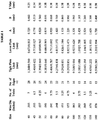
- Typically the files are made in a variety of working lengths varying from 19-30 mm. The specific variables which are typically controlled in fabricating such files are set forth in the Tables 1 and 2. In Tables 1 and 2 the variables A and B represent the minimum thickness of the transverse cross section at 16.00 mm and 3.00 mm, respectively, from the tip. The variables C and D represent the maximum thickness of the transverse cross section at 16.00 mm and 3.00 mm, respectively, from the tip.
- Table 1 describes the characteristics of a twisted rhomboidal file. In observing the longitudinal cross section of a rhomboidal file there are alternating
large flutes 153, resulting from the major axis of the rhombus, andsmall flutes 151, resulting from the minor axis of the rhombus. In Table 1 the column entitled Tight Flute Limit includes two values. The first value is the minimum acceptable length of asmall flute 151 resulting from the twisting of the minor axis of the rhombus. The second value is the minimum acceptable length of alarge flute 153 resulting from the twisting of the major axis of the rhombus. Similarly, the column entitled Loose Flute Limit includes two values. The first value is the maximum acceptable length of asmall flute 151 resulting from the twisting of the minor axis of the rhombus. The second value is the maximum acceptable length of alarge flute 153 resulting from the twisting of the major axis of the rhombus. In Table 1 the column labeled T max represents the maximum acceptable length of the untwisted portion at the distal tip of the file. In Table 2 the value L is the length of the ground portion of the rod. - Referring now to
Fig. 7 , anapparatus 200 is shown for forming a superelastic endodontic file blank 202 into a fluted, superelastic file. File blank 202 has been ground, such as in accordance with the above descriptions, before being fluted byapparatus 200.Apparatus 200 generally comprises arotary motion mechanism 204 operatively connected to a linear oraxial motion mechanism 206 similar toapparatus 10 ofFig. 1 . Eachmechanism Rotary motion mechanism 204 andlinear motion mechanism 206 may be conventional mechanisms known in the art for forming helical flutes on endodontic files. Eachmechanism electric motor 210. Agear drive 212 is connected in a conventional manner between an output 210a ofmotor 210 andlinear motion mechanism 206 to convert the rotary motion ofmotor 210 into linear motion.Gear drive 212 is shown to simply include two gears 212a, 212b, for simplicity, but it will be understood that idler gears may be used between gears 212a, 212b. Such idler gears are conventionally used to set the material feed rate. Asupport plate 220 is provided generally for connectingrotary motion mechanism 204 tolinear motion mechanism 206.Support plate 220 can also serve as a mounting plate for a mechanism (not shown) used to raise andlower apparatus 200, for reasons to be described. -
Rotary motion mechanism 204 further comprises arotary shaft 222 which may be directly coupled to output shaft 210a ofmotor 210. Aconventional collet 224 is provided for holding a proximal end ofsuperelastic file blank 202. Superelastic file blank 202 further has its ground portion or working length held between a pair of spring-loadedclamping jaws Fig. 8 . Clampingjaws lower end 230a of a clampingjaw support 230. Clampingjaw support 230 preferably has a conventional biasing mechanism to forcejaws jaw support 230 holds a helical threadedshaft 232 for rotation at a relativeupper end 230b. Helical threadedshaft 232 is also held within internal threads of gear member 212a ofgear drive 212 such that, upon operation ofgear drive 212 bymotor 210, gear member 212a will rotate and also rotate helical threadedshaft 232. This will moveshaft 232 linearly along its longitudinal axis thereby movingjaw support 230 andjaws superelastic file blank 202. - In accordance with one aspect of the invention, a
heated liquid 234 contained in avessel 236 receives the ground portion of file blank 202 during a twisting and fluting operation. The heatedliquid media 234 may, for example, comprise a salt solution or other suitable liquids such as oil. Preferably, the chosen liquid will have a boiling temperature preferably above the A f temperature or even above the Tw of the particular superelastic material. Presently, it is contemplated that a suitable operating temperature forliquid 234 is approximately 500°C or above. Again, it is preferable that the liquid does boil at the chosen operating temperature.Liquid 234 may be heated by any conventional manner, such as with anelectrical heating element 238 or a heating jacket. - For purposes of describing the operation of the
apparatus 200 shown inFigs. 7 and 8 , one contemplated example involves placing aground file blank 202, formed of a superelastic metallic alloy and formed with a rhomboid cross section as generally described above, withincollet 224. Clampingjaws adjacent collet 224.Apparatus 200 may then be lowered toward a heated liquid comprised of a salt solution heated to a temperature of about 500°C. Blank 202 should be lowered until the ground portion is submerged withinheated liquid 234. After about five seconds, a fluting operation may be carried out by moving linear oraxial motion mechanism 206 downwardly at a speed of about 6 inches/min. Rotation of blank 202 may be carried out bymechanism 204 at a corresponding rate which forms a desired number of twists. When thefluting jaws ground file blank 202, the fluting operation is complete andapparatus 200 may be lifted fromheated liquid 234 and removed fromcollet 224. Quenching or heat treating of the finished file may then be carried out if appropriate. - It will be appreciated that different alloy compositions will possess a different shape-memory characteristic, a different transformation temperature (Af), a different modulus of elasticity, and a different working temperature range Tw. It is within the skill of one in the art based upon the teachings of the present invention to adjust the heating, twisting and heat treating steps based upon the specific properties of the material used.
- While the present invention has been illustrated by a description of various embodiments and while these embodiments have been described in considerable detail, it is not the intention of the Applicants to restrict or in any way limit the scope of the appended claims to such detail. Additional advantages and modifications will readily appear to those skilled in the art. The invention in its broader aspects is therefore not limited to the specific details, representative apparatus and method as shown and described. This has been a description of the present invention, along with the preferred methods of practicing the present invention as currently known. However, the invention itself should only be defined by the appended claims, wherein we claim:
Claims (44)
- A method of making a file (11) from a rod (8) formed of a superelastic material and having a first and second end and a working length therebetween, the method comprising the steps of: grinding the rod to form a file preform (12) having a predetermined length, cross-sectional shape and taper along the working length thereof, the cross-sectional shape having corners (103, 107) which define longitudinal edges along the working length; and twisting the preform to permanently helically deform said preform and form helical shaped cutting edges from said longitudinal edges, wherein the preform is maintained in an austenite phase until immediately prior to twisting.
- The method of Claim 1 wherein the grinding step includes the steps of:retaining at least one rod in a predetermined position with respect to a grinding wheel; grinding a first elongate narrow surface along the working length of the rod;and alternatively indexing the rod about a longitudinal axis thereof and subsequently grinding another elongate narrow surface along the working length of the rod.
- The method of Claim 2 wherein the grinding step is performed with a rotatable grinding wheel having a surface which is convex.
- The method of Claim 2 wherein the grinding step is performed with a grinding wheel having surface which is concave.
- The method of any one of Claims 2 to 4 wherein the rod is indexed and ground two times after formation of the first elongate narrow surface to form a preform having a substantially triangular cross-section along the working length.
- The method of any one of Claims 2 to 4 wherein the rod is indexed and ground three times after formation of the first elongate narrow surface to form a preform having a substantially quadrilateral cross-section along the working length.
- The method of any one of Claims 2 to 4 wherein the rod is indexed approximately 90° after formation of each elongate narrow surface.
- The method of any one of Claims 2 to 4 wherein the rod is alternatively indexed approximately 60° and approximately 120° to form a file having a substantially rhomboidal cross-section.
- The method of any one of Claims 2 to 8 wherein the grinding step is performed upon a single rod retained in a rotatable collar.
- The method of any one of Claims 2 to 8 wherein the grinding step is performed upon a plurality of rods disposed in side-by-side parallel relationship.
- The method of Claim 10 wherein the plurality of rods are retained, in side-by-side parallel relationship, upon a rest by a movable retainer.
- The method of any one of Claims 2 to 11, wherein the twisting step includes the steps of: securing the first end of the file preform in a rotatable collet; securing the working length of the preform at a position proximate to the collet in a slidable non-rotatable work holder at a predetermined distance from said collet; rotating the collet and the portion of the file preform proximate the collet; and increasing the distance between said collet and said work holder.
- The method of Claim 12 wherein the rotating step is performed at a predetermined rotation rate; the distance increasing step is performed at a predetermined axial speed; and further comprising the step of: controlling the rotation rate and the speed to form a file having a predetermined twist rate.
- The method of any one of Claims 2 to 13 further comprising the step of heating the preform by an electrical heating process selected from the group consisting of radiant, joulian and induction heating.
- The method of any one of Claims 2 to 13 further comprising the step of heating the preform by internal friction during the twisting step.
- The method of any one of Claims 2 to 13 further comprising the step of heating the preform in a bath of heated liquid.
- The method of any preceding claim wherein the grinding step is performed using a rotary grinding wheel having a surface speed of between about 914 and 2438 surface metres per minute (3,000 and 8,000 surface feet per minute).
- The method of Claim 17 wherein the grinding step is performed using a rotary grinding wheel having a surface speed of about 1524 surface metres per minute (5,000 surface feet per minute).
- The method of either Claim 17 or Claim 18 wherein the grinding step is performed using a material feed rate of between about 15 and 30 lineal metres per minute (50 and 100 lineal feet per minute).
- The method of Claim 19 wherein the material feed rate is about 23 lineal metres per minute (75 lineal feet per minute).
- The method of any one of Claims 1 to 13 further comprising the step of heating to a temperature above the austenite finish temperature Af of the superelastic material prior to twisting.
- The method of any one of Claims 1 to 13 or 21 further comprising the step of heating the blank to a temperature of about 93°C-240°C (200°-400°F) prior to twisting.
- The method of any one of Claims 21 or 22 wherein the heating step if performed by an electrical heating process selected from the group consisting of radiant, joulian and induction heating.
- The method of any one of Claims 21 or 22 wherein the heating step is performed in a bath of heated liquid.
- The method of any one of Claims 16 or 24 wherein the bath is comprised of salt solution or of oil.
- The method of any preceding claim wherein the superelastic material transforms to the martensite phase during twisting.
- The method of Claim 26 wherein the martensite phase is a stress induced martensite phase.
- The method of Claim 27 wherein the stress induced martensite phase includes plastic deformation during twisting.
- An endodontic file (11) comprising: a shaft including a working length portion formed of a material exhibiting superelastic characteristics, said working length portion having a predetermined transverse cross sectional area, a longitudinal axis, and a plurality of apices defining cutting edges, said working length portion being permanently plastically deformed by twisting about its longitudinal axis to form said cutting edges at the apices thereof, wherein the preform is maintained in an austenite phase until immediately prior to twisting and wherein said working length includes at least three of said cutting edges helically arranged about the working length of said shaft.
- The endodontic file of claim 29 further comprising helical surfaces arranged between adjacent cutting edges, said helical surfaces being substantially flat when viewed in transverse cross section.
- The endodontic file of claim 29 wherein said working length includes at least four of said cutting edges helically arranged along said shaft.
- The endodontic file of claim 29 further comprising a flat side arranged between adjacent cutting edges.
- The endodontic file of any one of claims 29 to 32 wherein said material is selected from the group consisting of near-equiatomic Ni-Ti, Ni-Ti-Nb alloys, Ni-Ti-Fe alloys, Ni-Ti-Cu alloys, Ni-Ti-Nb alloys and beta-phase titanium.
- The endodontic file of any one of claims 29 to 32 wherein said material is at least about 40 atomic percent Ti.
- The endodontic file of any one of claims 29 to 34 wherein said material is about 50.8 atomic percent Ti and about 49.2 atomic percent Ni.
- The endodontic file of any one of claims 29 to 35 wherein said predetermined transverse cross-sectional shape is selected from the group consisting of three and four sided polygons.
- The endodontic file of any one of claims 29 to 35 wherein said predetermined transverse cross-sectional area has a substantially rhomboidal shape.
- The endodontic file of claim 37 wherein said substantially rhomboidal shape has angles of about 60°-120°-60°-120°.
- Apparatus for forming an endodontic instrument (10) from a superelastic rod-shaped blank (12), the apparatus comprising a linear motion mechanism including a clamping element (14) for holding a portion of said blank (12) and moving said clamping element along said blank, a rotary motion mechanism (9) for holding and rotating said instrument, said rotary motion mechanism being operatively coupled to said linear motion mechanism for rotating said blank as said clamping element moves therealong to form a helically fluted instrument (11), and a source of heat disposed proximate said linear and rotary motion mechanisms for heating said blank at least prior to operation of the linear and rotary motion mechanisms.
- The apparatus of claim 39, wherein the source of heat is an electrical heating source selected from the group consisting of radiant, joulian and conductive types of heating sources.
- The apparatus of claim 39 wherein the source of heat is a heated liquid.
- The apparatus of claim 41 wherein said liquid is contained in a vessel operatively coupled to a heating element with said linear and rotary motion mechanisms mounted above said vessel for vertical movement into said vessel.
- The apparatus of claim 42 wherein said liquid contains a salt.
- The apparatus of claim 39 wherein said rotary motion mechanism includes a collet adapted to hold an endodontic file blank.
Priority Applications (1)
| Application Number | Priority Date | Filing Date | Title |
|---|---|---|---|
| EP10180880.6A EP2272460B1 (en) | 1998-01-27 | 1999-01-15 | Superelastic endodontic instrument and method of manufacture therefor |
Applications Claiming Priority (3)
| Application Number | Priority Date | Filing Date | Title |
|---|---|---|---|
| US09/014,139 US6149501A (en) | 1997-09-26 | 1998-01-27 | Superelastic endodontic instrument, method of manufacture, and apparatus therefor |
| US14139 | 1998-01-27 | ||
| PCT/US1999/000895 WO1999037235A2 (en) | 1998-01-27 | 1999-01-15 | Superelastic endodontic instrument, method of manufacture, and apparatus therefor |
Related Child Applications (2)
| Application Number | Title | Priority Date | Filing Date |
|---|---|---|---|
| EP10180880.6A Division-Into EP2272460B1 (en) | 1998-01-27 | 1999-01-15 | Superelastic endodontic instrument and method of manufacture therefor |
| EP10180880.6A Division EP2272460B1 (en) | 1998-01-27 | 1999-01-15 | Superelastic endodontic instrument and method of manufacture therefor |
Publications (3)
| Publication Number | Publication Date |
|---|---|
| EP1051125A2 EP1051125A2 (en) | 2000-11-15 |
| EP1051125A4 EP1051125A4 (en) | 2004-10-27 |
| EP1051125B1 true EP1051125B1 (en) | 2018-08-15 |
Family
ID=21763778
Family Applications (2)
| Application Number | Title | Priority Date | Filing Date |
|---|---|---|---|
| EP99902283.3A Expired - Lifetime EP1051125B1 (en) | 1998-01-27 | 1999-01-15 | Superelastic endodontic instrument, method of manufacture, and apparatus therefor |
| EP10180880.6A Expired - Lifetime EP2272460B1 (en) | 1998-01-27 | 1999-01-15 | Superelastic endodontic instrument and method of manufacture therefor |
Family Applications After (1)
| Application Number | Title | Priority Date | Filing Date |
|---|---|---|---|
| EP10180880.6A Expired - Lifetime EP2272460B1 (en) | 1998-01-27 | 1999-01-15 | Superelastic endodontic instrument and method of manufacture therefor |
Country Status (7)
| Country | Link |
|---|---|
| US (1) | US6149501A (en) |
| EP (2) | EP1051125B1 (en) |
| JP (2) | JP4540024B2 (en) |
| AU (1) | AU2230299A (en) |
| CO (1) | CO4840516A1 (en) |
| TW (1) | TW462883B (en) |
| WO (1) | WO1999037235A2 (en) |
Families Citing this family (48)
| Publication number | Priority date | Publication date | Assignee | Title |
|---|---|---|---|---|
| FR2798277B1 (en) * | 1999-09-10 | 2002-04-19 | Micro Mega Sa | DENTAL REST TYPE CHANNEL INSTRUMENT AND METHODS OF MAKING |
| US7249414B2 (en) | 1999-09-10 | 2007-07-31 | Micro Mega, S.A. | Method for making a root canal instrument |
| US7094055B2 (en) * | 2001-05-30 | 2006-08-22 | Steven Senia | Endodontic reamer and a method for manufacturing endodontic reamers and files |
| US6966774B2 (en) * | 2001-08-16 | 2005-11-22 | Cloudland Institute, Llc. | Endodontic instrument having notched cutting surfaces |
| US7779542B2 (en) * | 2002-04-18 | 2010-08-24 | Ormco Corporation | Method of manufacturing a dental instrument |
| US6783438B2 (en) * | 2002-04-18 | 2004-08-31 | Ormco Corporation | Method of manufacturing an endodontic instrument |
| DE10233030B3 (en) * | 2002-07-20 | 2004-02-19 | Gebr. Brasseler Gmbh & Co. Kg | Root canal instrument |
| US20060265858A1 (en) * | 2002-08-15 | 2006-11-30 | Mcspadden John T | Endodontic instrument having notched cutting surfaces |
| US20080213720A1 (en) * | 2003-05-13 | 2008-09-04 | Ultradent Products, Inc. | Endodontic instruments manufactured using chemical milling |
| US6968619B2 (en) * | 2003-05-13 | 2005-11-29 | Ultradent Products, Inc. | Method for manufacturing endodontic instruments |
| JP4186713B2 (en) * | 2003-05-29 | 2008-11-26 | マニー株式会社 | Root canal treatment instrument and manufacturing method |
| US7967605B2 (en) | 2004-03-16 | 2011-06-28 | Guidance Endodontics, Llc | Endodontic files and obturator devices and methods of manufacturing same |
| JP4247346B2 (en) * | 2004-03-30 | 2009-04-02 | マニー株式会社 | Grinding method of square taper with cross section for therapeutic device and therapeutic device |
| ES2587931T3 (en) | 2004-06-08 | 2016-10-27 | Gold Standard Instruments, LLC | Dental instruments comprising titanium |
| DE102004029065A1 (en) | 2004-06-16 | 2006-01-26 | Siemens Ag | Crankshaft synchronous acquisition of analog signals |
| US20060008766A1 (en) * | 2004-07-09 | 2006-01-12 | Fischer Dan E | Dental instruments made from super-elastic alloys |
| JP4621851B2 (en) * | 2004-11-29 | 2011-01-26 | マニー株式会社 | Root canal treatment instrument |
| FR2886837B1 (en) | 2005-06-14 | 2008-04-11 | Micro Mega Int Mfg Sa | DRAFT FOR THE MANUFACTURE OF AN ENDODONTIC INSTRUMENT AND METHOD FOR MANUFACTURING THE SAME |
| US7648599B2 (en) * | 2005-09-13 | 2010-01-19 | Sportswire, LLC | Method of preparing nickel titanium alloy for use in manufacturing instruments with improved fatigue resistance |
| US20070101827A1 (en) * | 2005-11-01 | 2007-05-10 | Quan Nancy N | Endodontic Instrument |
| US20070119813A1 (en) * | 2005-11-28 | 2007-05-31 | Texas Instruments Incorporated | Gate patterning method for semiconductor processing |
| US8413330B2 (en) * | 2008-03-13 | 2013-04-09 | William B. Johnson | Longitudinally ground file having increased resistance to torsional and cyclic fatigue failure |
| US20100233648A1 (en) * | 2008-09-09 | 2010-09-16 | Mcspadden John | Endodontic instrument and method of manufacturing |
| WO2011062970A1 (en) * | 2009-11-17 | 2011-05-26 | Johnson William B | Improved fatigue-resistant nitinol instrument |
| US9005377B2 (en) | 2009-11-20 | 2015-04-14 | D & S Dental, Llc | Method of modifying a physical property of an endodontic instrument |
| US10196713B2 (en) | 2009-11-20 | 2019-02-05 | Dentsply Sirona Inc. | Medical instrument with modified memory and flexibility properties and method |
| US20110159458A1 (en) * | 2009-11-20 | 2011-06-30 | Heath Derek E | Endodontic Instrument With Modified Memory and Flexibility Properties and Method |
| US8911573B2 (en) | 2009-11-20 | 2014-12-16 | D & S Dental, Llc | Medical instrument with modified memory and flexibility properties and method |
| US8644978B1 (en) | 2010-01-20 | 2014-02-04 | D & S Dental, Llc | Machining apparatus and method of making endodontic instruments |
| US20110271529A1 (en) | 2010-05-10 | 2011-11-10 | Dentsply International Inc. | Endodontic rotary instruments made of shape memory alloys in their martensitic state and manufacturing methods |
| US8916009B2 (en) | 2011-05-06 | 2014-12-23 | Dentsply International Inc. | Endodontic instruments and methods of manufacturing thereof |
| EP2740811B1 (en) * | 2010-08-24 | 2018-08-01 | Ormco Corporation | Method for shape setting a shape memory alloy wire |
| CH704235B1 (en) | 2010-12-16 | 2015-09-30 | Fkg Dentaire Sa | The endodontic instrument for root canal bore of a tooth. |
| IL216587A (en) * | 2011-11-24 | 2014-09-30 | Medic Nrg Ltd | Endodontic file having an outer spiral cord |
| JP5870659B2 (en) * | 2011-12-05 | 2016-03-01 | ニプロ株式会社 | Puncture needle manufacturing method and puncture needle |
| US20130240092A1 (en) * | 2012-03-15 | 2013-09-19 | Dentsply International Inc. | Medical instrument made of monocrystalline shape memory alloys and manufacturing methods |
| US20180142377A1 (en) * | 2016-11-21 | 2018-05-24 | Dentsply International Inc. | Medical Instrument Made of Monocrystalline Shape Memory Alloys and Manufacturing Methods |
| JP6370373B2 (en) * | 2013-06-20 | 2018-08-08 | デンツプライ シロナ インコーポレーテッド | Endodontic instrument |
| US10695820B2 (en) * | 2014-09-09 | 2020-06-30 | Gold Standard Instruments, LLC | Method for forming an endodontic instrument or device |
| US11033358B2 (en) | 2015-09-23 | 2021-06-15 | Coltène/Whaledent Ag | Method for producing blanks for endodontic instruments |
| EP3156163B1 (en) | 2015-09-23 | 2022-03-16 | Coltène/Whaledent GmbH + Co. KG | Method for producing blanks for endodontic instruments and such blanks |
| US10543060B2 (en) | 2015-12-03 | 2020-01-28 | Ormco Corporation | Fluted endodontic file |
| US10716645B2 (en) | 2016-10-22 | 2020-07-21 | Ormco Corporation | Variable heat-treat endodontic file |
| EP3375557B1 (en) | 2017-03-15 | 2023-08-23 | Coltène/Whaledent GmbH + Co. KG | Method for producing blanks for endodontic instruments, and such blanks |
| USD842474S1 (en) | 2017-10-20 | 2019-03-05 | Ormco Corporation | Endodontic file |
| JP2022030793A (en) * | 2020-08-07 | 2022-02-18 | マニー株式会社 | Dental file |
| JP7370952B2 (en) * | 2020-10-06 | 2023-10-30 | マニー株式会社 | dental files |
| CN113400144B (en) * | 2021-04-21 | 2023-03-07 | 桐乡市三精自动化科技有限公司 | Tool part |
Family Cites Families (22)
| Publication number | Priority date | Publication date | Assignee | Title |
|---|---|---|---|---|
| JPS6051904B2 (en) * | 1981-09-07 | 1985-11-16 | セイコーエプソン株式会社 | orthodontic components |
| JPS5917341A (en) * | 1982-07-15 | 1984-01-28 | 株式会社松谷製作所 | Production of h files |
| US4443193A (en) * | 1983-02-08 | 1984-04-17 | Roane James B | Endodontic instrument |
| JPS60129042A (en) * | 1983-12-15 | 1985-07-10 | 株式会社松谷製作所 | Production of dental reamer or file |
| JPS60138513U (en) * | 1984-02-23 | 1985-09-13 | 株式会社 松谷製作所 | dental root canal cutting tool |
| DE3429277C2 (en) * | 1984-08-08 | 1994-02-17 | Matsutani Seisakusho | Broaching or milling tool for broaching or milling a tooth root canal, and method and device for manufacturing such a broaching or milling tool |
| JPH0818080B2 (en) * | 1986-08-07 | 1996-02-28 | 日立金属株式会社 | Twisting method |
| JP3044623B2 (en) * | 1990-01-12 | 2000-05-22 | ウイリアム・ビー・ジヨンソン | Improved device used in applying filling material to endodontically prepared root canals |
| US5044947A (en) * | 1990-06-29 | 1991-09-03 | Ormco Corporation | Orthodontic archwire and method of moving teeth |
| EP0491349B1 (en) * | 1990-12-18 | 1998-03-18 | Advanced Cardiovascular Systems, Inc. | Method of manufacturing a Superelastic guiding member |
| US5106298A (en) * | 1991-04-03 | 1992-04-21 | Heath Derek E | Endodontic dental instrument |
| US5527205A (en) * | 1991-11-05 | 1996-06-18 | Tulsa Dental Products, L.L.C. | Method of fabricating an endodontic instrument |
| US5302129A (en) * | 1991-11-19 | 1994-04-12 | Heath Derek E | Endodontic procedure and instrument |
| US5429501A (en) * | 1994-03-28 | 1995-07-04 | Ormco Corporation | Orthodontic coil springs and methods |
| US5897316A (en) * | 1994-04-28 | 1999-04-27 | Buchanan; Leonard Stephen | Endodontic treatment system |
| JP3375765B2 (en) * | 1994-12-27 | 2003-02-10 | マニー株式会社 | Method for manufacturing root canal treatment device and root canal treatment device |
| CH690538A5 (en) * | 1995-03-24 | 2000-10-13 | Maillefer Instr Sa | Instrument set for the boring of radicular dental canals. |
| JP3490793B2 (en) * | 1995-04-11 | 2004-01-26 | 古河電気工業株式会社 | Orthodontic appliances |
| US5605460A (en) * | 1995-04-26 | 1997-02-25 | Tulsa Dental Products, L.L.C. | Endodontic instrument and procedure |
| US5653590A (en) * | 1995-06-06 | 1997-08-05 | Tulsa Dental Products, L.L.C. | Kit of endodontic instruments and method of utilizing same |
| DE19522033A1 (en) * | 1995-06-17 | 1996-12-19 | Hilti Ag | Process for producing rotary drilling tools |
| US5984679A (en) * | 1997-09-26 | 1999-11-16 | Ormco Corporation | Method of manufacturing superelastic endodontic files and files made therefrom |
-
1998
- 1998-01-27 US US09/014,139 patent/US6149501A/en not_active Expired - Lifetime
-
1999
- 1999-01-15 EP EP99902283.3A patent/EP1051125B1/en not_active Expired - Lifetime
- 1999-01-15 JP JP2000528226A patent/JP4540024B2/en not_active Expired - Lifetime
- 1999-01-15 WO PCT/US1999/000895 patent/WO1999037235A2/en active Application Filing
- 1999-01-15 AU AU22302/99A patent/AU2230299A/en not_active Abandoned
- 1999-01-15 EP EP10180880.6A patent/EP2272460B1/en not_active Expired - Lifetime
- 1999-01-27 CO CO99004367A patent/CO4840516A1/en unknown
- 1999-01-27 TW TW088101239A patent/TW462883B/en active
-
2010
- 2010-03-17 JP JP2010060930A patent/JP5162611B2/en not_active Expired - Lifetime
Also Published As
| Publication number | Publication date |
|---|---|
| JP2010131457A (en) | 2010-06-17 |
| US6149501A (en) | 2000-11-21 |
| AU2230299A (en) | 1999-08-09 |
| EP1051125A4 (en) | 2004-10-27 |
| JP5162611B2 (en) | 2013-03-13 |
| CO4840516A1 (en) | 1999-09-27 |
| JP4540024B2 (en) | 2010-09-08 |
| WO1999037235A3 (en) | 2000-06-22 |
| WO1999037235A2 (en) | 1999-07-29 |
| JP2002500919A (en) | 2002-01-15 |
| TW462883B (en) | 2001-11-11 |
| EP1051125A2 (en) | 2000-11-15 |
| EP2272460B1 (en) | 2018-10-24 |
| EP2272460A2 (en) | 2011-01-12 |
| EP2272460A3 (en) | 2012-12-26 |
Similar Documents
| Publication | Publication Date | Title |
|---|---|---|
| EP1051125B1 (en) | Superelastic endodontic instrument, method of manufacture, and apparatus therefor | |
| US5984679A (en) | Method of manufacturing superelastic endodontic files and files made therefrom | |
| EP1354566B1 (en) | Method of manufacturing an endodontic instrument | |
| US7779542B2 (en) | Method of manufacturing a dental instrument | |
| EP3345566B1 (en) | Methods of manufacturing endodontic instruments | |
| US20100233648A1 (en) | Endodontic instrument and method of manufacturing | |
| US20080050697A1 (en) | Endodontic Instruments | |
| WO2001015832A1 (en) | Barbed endodontic instrument | |
| US20190284664A1 (en) | Endodontic instruments and methods of manufacturing thereof | |
| US20230320815A1 (en) | Endodontic files with hybrid metallurgical elastic characteristics and identification colors | |
| CN117770990A (en) | Root canal file product with mixed metallurgical elastic characteristic and manufacturing method thereof | |
| WO2007053746A9 (en) | Endodontic instrument |
Legal Events
| Date | Code | Title | Description |
|---|---|---|---|
| PUAI | Public reference made under article 153(3) epc to a published international application that has entered the european phase |
Free format text: ORIGINAL CODE: 0009012 |
|
| 17P | Request for examination filed |
Effective date: 20000728 |
|
| AK | Designated contracting states |
Kind code of ref document: A2 Designated state(s): DE FR |
|
| A4 | Supplementary search report drawn up and despatched |
Effective date: 20040915 |
|
| RIC1 | Information provided on ipc code assigned before grant |
Ipc: 7A 61C 5/02 B Ipc: 7A 61C 5/04 A |
|
| 17Q | First examination report despatched |
Effective date: 20070423 |
|
| RAP1 | Party data changed (applicant data changed or rights of an application transferred) |
Owner name: ORMCO CORPORATION |
|
| REG | Reference to a national code |
Ref country code: DE Ref legal event code: R079 Ref document number: 69945888 Country of ref document: DE Free format text: PREVIOUS MAIN CLASS: A61C0005040000 Ipc: A61C0005420000 |
|
| GRAP | Despatch of communication of intention to grant a patent |
Free format text: ORIGINAL CODE: EPIDOSNIGR1 |
|
| RIC1 | Information provided on ipc code assigned before grant |
Ipc: B24B 19/04 20060101ALI20180213BHEP Ipc: A61C 5/42 20170101AFI20180213BHEP Ipc: B24B 19/02 20060101ALI20180213BHEP |
|
| INTG | Intention to grant announced |
Effective date: 20180301 |
|
| GRAS | Grant fee paid |
Free format text: ORIGINAL CODE: EPIDOSNIGR3 |
|
| GRAA | (expected) grant |
Free format text: ORIGINAL CODE: 0009210 |
|
| AK | Designated contracting states |
Kind code of ref document: B1 Designated state(s): DE FR |
|
| REG | Reference to a national code |
Ref country code: DE Ref legal event code: R096 Ref document number: 69945888 Country of ref document: DE |
|
| REG | Reference to a national code |
Ref country code: DE Ref legal event code: R071 Ref document number: 69945888 Country of ref document: DE |
|
| RIC2 | Information provided on ipc code assigned after grant |
Ipc: B24B 19/04 20060101ALI20180213BHEP Ipc: B24B 19/02 20060101ALI20180213BHEP Ipc: A61C 5/42 20170101AFI20180213BHEP |
|
| REG | Reference to a national code |
Ref country code: DE Ref legal event code: R097 Ref document number: 69945888 Country of ref document: DE |
|
| PLBE | No opposition filed within time limit |
Free format text: ORIGINAL CODE: 0009261 |
|
| STAA | Information on the status of an ep patent application or granted ep patent |
Free format text: STATUS: NO OPPOSITION FILED WITHIN TIME LIMIT |
|
| 26N | No opposition filed |
Effective date: 20190516 |